

Page 1

OGX-FR Series User Guide
Page 2

Thank You for Choosing Ross
You've made a great choice. We expect you will be very happy with your purchase of Ross Technology.
Our mission is to:
1. Provide a Superior Customer Experience
• offer the best product quality and support
2. Make Cool Practical Technology
• develop great products that customers love
Ross has become well known for the Ross Video Code of Ethics. It guides our interactions and
empowers our employees. I hope you enjoy reading it below.
If anything at all with your Ross experience does not live up to your expectations be sure to reach out to
us at solutions@rossvideo.com.
David Ross
CEO, Ross Video
dross@rossvideo.com
Ross Video Code of Ethics
Any company is the sum total of the people that make things happen. At Ross, our employees are a
special group. Our employees truly care about doing a great job and delivering a high quality customer
experience every day. This code of ethics hangs on the wall of all Ross Video locations to guide our
behavior:
1. We will always act in our customers’ best interest.
2. We will do our best to understand our customers’ requirements.
3. We will not ship crap.
4. We will be great to work with.
5. We will do something extra for our customers, as an apology, when something big goes wrong and
it's our fault.
6. We will keep our promises.
7. We will treat the competition with respect.
8. We will cooperate with and help other friendly companies.
9. We will go above and beyond in times of crisis. If there's no one to authorize the required action in
times of company or customer crisis - do what you know in your heart is right. (You may rent
helicopters if necessary.)
Page 3

OGX-FR Series · User Guide
• Ross Part Number: 8322DR-204-01
• Release Date: June 14, 2018.
The information contained in this Guide is subject to change without notice or obligation.
Copyright
©2018 Ross Video Limited, Ross®, and any related marks are trademarks or registered trademarks of Ross Video
Limited. All other trademarks are the property of their respective companies. PATENTS ISSUED and PENDING.
All rights reserved. No part of this publication may be reproduced, stored in a retrieval system, or transmitted in any
form or by any means, mechanical, photocopying, recording or otherwise, without the prior written permission of
Ross Video. While every precaution has been taken in the preparation of this document, Ross Video assumes no
responsibility for errors or omissions. Neither is any liability assumed for damages resulting from the use of the
information contained herein.
Patents
Patent numbers US 7,034,886; US 7,508,455; US 7,602,446; US 7,802,802 B2; US 7,834,886; US 7,914,332; US
8,307,284; US 8,407,374 B2; US 8,499,019 B2; US 8,519,949 B2; US 8,743,292 B2; GB 2,419,119 B; GB
2,447,380 B; and other patents pending.
Notice
The material in this manual is furnished for informational use only. It is subject to change without notice and should
not be construed as commitment by Ross Video Limited. Ross Video Limited assumes no responsibility or liability
for errors or inaccuracies that may appear in this manual.
Safety Notices
Refer to the “Important Regulatory and Safety Notices” document that accompanied your product.
Statement of Compliance
This product has been determined to be compliant with the applicable standards, regulations, and directives for the
countries where the product is marketed.
Compliance documentation, such as certification or Declaration of Compliance for the product is available upon
request by contacting techsupport@rossvideo.com. Please include the product; model number identifiers and serial
number and country that compliance information is needed in request.
EMC Notices
US FCC Part 15
This equipment has been tested and found to comply with the limits for a class A Digital device, pursuant to part 15
of the FCC Rules.
These limits are designed to provide reasonable protection against harmful interference when the equipment is
operated in a Commercial environment. This equipment generates, uses, and can radiate radio frequency energy
and, if not installed and used in accordance with the instruction manual, may cause harmful interference to radio
Page 4

communications. Operation of this equipment in a residential area is likely to cause harmful interference in which
Type of Equipment User’s Guide
A
(߶הࡈ ؏ܞݦࢢ)
Class A Equipment
(Industrial Broadcasting &
Communication Equipment)
ࢇ Е ߶הࡈ(A) ࢷળࢶଢԻ۰ શ
ӖЕ یࡈЕ ࢇ ࢺࡶ ࣯ࢂଜݤ Ԃ
ֲ, ɼࢽ࠹ࢂ ࠇ߾۰ یࡈଜЕ ʨࡶ ּࢶࡳԻ
ଢТЬ.
This equipment is Industrial (Class A)
electromagnetic wave suitability equipment and
seller or user should take notice of it, and this
equipment is to be used in the places except for home.
case the user will be required to correct the interference at his own expense.
Notice — Changes or modifications to this equipment not expressly approved by Ross Video Ltd. could
void the user’s authority to operate this equipment.
Canada
This Class “A” digital apparatus complies with Canadian ICES-003 and part 15 of the FCC Rules.
Cet appareil numerique de la classe “A” est conforme a la norme NMB-003 du Canada.
European Union
This equipment is in compliance with the essential requirements and other relevant provisions established under
regulation (EC) No 765/2008 and Decision No 768/2008/EC referred to as the “New Legislative Framework”.
Warning — This equipment is compliant with Class A of CISPR 32. In a residential environment this
equipment may cause radio interference.
Australia/New Zealand
This equipment is in compliance with the provisions established under the Radiocommunications Act 1992 and
Radiocommunications Labeling (Electromagnetic Compatibility) Notice 2008.
Korea
This equipment is in compliance with the provisions established under the Radio Waves Act.
Class A equipment (Broadcasting and communications service for business use)
This device is a business-use (Class A) EMC-compliant device. The seller and user are advised to be aware of this
fact. This device is intended for use in areas outside home.
International
This equipment has been tested under the requirements of CISPR 22:2008 or CISPR 32:2015 and found to comply
with the limits for a Class A Digital device.
Notice — This is a Class A product. In domestic environments, this product may cause radio
interference, in which case the user may have to take adequate measures.
Maintenance/User Serviceable Parts
Routine maintenance to this openGear product is not required. This product contains no user serviceable parts. If
the module does not appear to be working properly, please contact Technical Support using the numbers listed
under the “Contact Us” section of this manual. All openGear products are covered by a generous 5-year warranty
Page 5

and will be repaired without charge for materials or labor within this period. See the “Warranty and Repair
Policy” section in this manual for details.
Environmental Information
The equipment may contain hazardous substances that could impact health and the environment.
To avoid the potential release of those substances into the environment and to diminish the need for the extraction
of natural resources, Ross Video encourages you to use the appropriate take-back systems. These systems will reuse
or recycle most of the materials from your end-of-life equipment in an environmentally friendly and health
conscious manner.
The crossed-out wheeled bin symbol invites you to use these systems.
If you need more information on the collection, reuse, and recycling systems, please contact your local or regional
waste administration. You can also contact Ross Video for more information on the environmental performances of
our products.
Company Address
Ross Video Limited
8 John Street
Iroquois, Ontario
Canada, K0E 1K0
General Business Office:
Technical Support:
After Hours Emergency:
E-mail (Technical Support): techsupport@rossvideo.com
E-mail (General Information): solutions@rossvideo.com
Website: http://www.rossvideo.com
Ross Video Incorporated
P.O. Box 880
Ogdensburg, New York
USA 13669-0880
Fax:
(+1) 613
(+1) 613
(+1) 613
(+1) 613
652 4886
652 4425
652 4886
349 0006
Page 6

Page 7

Contents
Introduction 9
Related Publications .................................................................................................................................................9
Documentation Conventions ....................................................................................................................................9
Interface Elements .................................................................................................................................................9
User Entered Text .................................................................................................................................................9
Referenced Guides ................................................................................................................................................9
Menu Sequences ....................................................................................................................................................9
Important Instructions .........................................................................................................................................10
Contacting Technical Support ................................................................................................................................ 10
Before You Begin 11
Overview ................................................................................................................................................................11
Features ..................................................................................................................................................................11
Workflow ...............................................................................................................................................................11
Hardware Overview 13
Front Panel Overview ............................................................................................................................................13
OGX-FR Interior .................................................................................................................................................... 14
Rear Panel Overview ............................................................................................................................................. 15
openGear Rear Modules ........................................................................................................................................15
Supports DFR-8321 and OG3-FR Rear Modules ............................................................................................... 15
Identifying an OGX-FR Rear Module ................................................................................................................16
Rear Module Types ............................................................................................................................................. 16
Physical Installation 17
Before You Begin ..................................................................................................................................................17
Static Discharge .................................................................................................................................................. 17
Ventilation and Cooling ......................................................................................................................................... 17
Ventilation ........................................................................................................................................................... 17
Cooling Fan Module ...........................................................................................................................................17
Airflow Requirements .........................................................................................................................................18
Installation Requirements ......................................................................................................................................18
Installing the Rear Support Bars and Brackets ......................................................................................................18
Installing the FSB-OGX ...................................................................................................................................... 18
Connecting to a Power Supply ............................................................................................................................... 19
Power Supply Connectors (PSU1, PSU2) ........................................................................................................... 20
Power Cable Connection .....................................................................................................................................20
Ethernet Cabling 21
Cabling the Ethernet Port on the OGX-FR Frame ................................................................................................. 21
Required Pinouts .................................................................................................................................................21
Connecting to a Network ....................................................................................................................................21
Reference Cabling 23
GFC-8322 Overview ..............................................................................................................................................23
Connecting a Video Reference Source ..................................................................................................................23
Connecting to a Reference Source ......................................................................................................................23
Looping the Reference Signals ...........................................................................................................................23
Troubleshooting .....................................................................................................................................................24
OGX-FR Series User Guide (v1.0) Contents • i
Page 8

Using DashBoard 25
Overview ................................................................................................................................................................25
Launching DashBoard ............................................................................................................................................25
Using the Automatic Detection Feature .................................................................................................................25
Manually Adding OGX-FR Frames to DashBoard ................................................................................................25
Re-naming the OGX-FR Frame in the Tree View .................................................................................................26
Removing an OGX-FR Frame from the Tree View in DashBoard ........................................................................27
Auto-Discovery ...................................................................................................................................................28
Using DashBoard to Access openGear Cards in the OGX-FR Frame ...................................................................28
Maintenance 31
Installing a Frame Power Supply ...........................................................................................................................31
Fan Filter Maintenance ...........................................................................................................................................31
Cleaning the Frame Air Filter .............................................................................................................................31
Replacing the Frame Air Filter ............................................................................................................................32
Replacing the Cooling Fan Module .......................................................................................................................33
Replacing the OGX-FR Door ..............................................................................................................................33
Technical Specifications 35
Dimensions .............................................................................................................................................................35
PS-OGX .................................................................................................................................................................35
Card Slots ...............................................................................................................................................................35
Frame Controller and Fans .....................................................................................................................................36
GFC-8322 ...............................................................................................................................................................36
Reference Inputs .....................................................................................................................................................36
Environment ...........................................................................................................................................................36
Service Information 37
Warranty and Repair Policy ...................................................................................................................................37
Glossary 39
ii • Contents OGX-FR Series User Guide (v1.0)
Page 9

Introduction
This guide covers the installation and use of the OGX-FR openGear High Density Modular Frame. The following
chapters are included:
•“Introduction” summarizes the guide and provides important terms, and conventions.
•“Before You Begin” provides general information to keep in mind before installing and configuring your
OGX-FR.
•“Hardware Overview” provides a basic introduction to the OGX-FR hardware features.
•“Physical Installation” provides instructions for the physical installation of the OGX-FR.
•“Ethernet Cabling” provides an overview of connecting input and output devices to the OGX-FR.
•“Reference Cabling” provides an overview of the reference distribution and how to connect a reference source
to the OGX-FR.
•“Using DashBoard” outlines the Diagnostic Panel features and displaying the OGX-FR in DashBoard.
•“Maintenance” provides instructions for cleaning the fan filter and replacing a failed Cooling Fan Module.
•“Technical Specifications” provides the specifications for the OGX-FR.
•“Service Information” provides information on the warranty and repair policy for your OGX-FR.
•“Glossary”provides a list of terms used throughout this guide.
Related Publications
It is recommended to consult the following Ross documentation before installing and configuring your OGX-FR:
• DashBoard User Manual, Ross Part Number: 8351DR-004
• MFC-OG3-N User Manual, Ross Part Number: 8322DR-004
Documentation Conventions
Special text formats are used in this guide to identify parts of the user interface, text that a user must enter, or a
sequence of menus and sub-menus that must be followed to reach a particular command.
Interface Elements
Bold text is used to identify a user interface element such as a dialog box, menu item, or button. For example:
In the Network tab, click
User Entered Text
Courier text is used to identify text that a user must enter. For example:
In the Language box, enter
Referenced Guides
Text set in bold and italic represent the titles of referenced guides, manuals, or documents. For example:
Apply.
English.
For more information, refer to the DashBoard User Manual.
Menu Sequences
Menu arrows are used in procedures to identify a sequence of menu items that you must follow. For example, if a
step reads “File > Save As,” you would click the File menu and then click Save As.
OGX-FR Series User Guide (v1.0) Introduction • 9
Page 10

Important Instructions
Star icons are used to identify important instructions or features. For example:
Contact your IT department before connecting to your facility network to ensure that there are no conflicts. They
will provide you with an appropriate value for the IP Address, Subnet Mask, and Gateway for your device.
Contacting Technical Support
At Ross Video, we take pride in the quality of our products, but if problems occur, help is as close as the nearest
telephone.
Our 24-hour Hot Line service ensures you have access to technical expertise around the clock. After-sales service
and technical support is provided directly by Ross Video personnel. During business hours (Eastern Time),
technical support personnel are available by telephone. After hours and on weekends, a direct emergency technical
support phone line is available. If the technical support person who is on call does not answer this line immediately,
a voice message can be left and the call will be returned shortly. This team of highly trained staff is available to
react to any problem and to do whatever is necessary to ensure customer satisfaction.
• Technical Support: (+1) 613-652-4886
• After Hours Emergency: (+1) 613-349-0006
• E-mail: techsupport@rossvideo.com
• Web site: http://www.rossvideo.com
10 • Introduction OGX-FR Series User Guide (v1.0)
Page 11

Before You Begin
If you have questions pertaining to the operation of OGX-FR, please contact us at the numbers listed in the section
“Contacting Technical Support”. Our technical staff is always available for consultation, training, or service.
Overview
The OGX-FR frame offers the flexibility of independent rear modules for connectivity to a wide array of interfaces
such as BNC, twisted-pair audio, and fiber. Each frame offers a full rear module that accommodates one card each,
or a high density split rear module that accommodates two cards each. Using the split rear module allows for up to
20 independent openGear solutions to be installed.
Cards and rear modules designed for the DFR-8321 frames are also supported by the OGX-FR frames. However,
some cards and rear modules may be designed specifically for the OGX-FR frames only. Refer to the
documentation for your openGear card for details on the frames you can use.
Features
The OGX-FR frame includes the following features:
• Two independent looping reference inputs feed all card slots
• Can house any mix of analog, digital, video and audio cards in the same frame
• Available with individual card specific modules for connector flexibility
• Optional redundant power supply is hot-swappable for 24/7 operation
• Power switch is accessible from front of the rack frame
• Power supplies are replaceable from the front of the frame without requiring rear-frame access
• Separate power cords to each supply for power feed redundancy
• PowerLock cord retainer mechanism guards against accidental power loss
• Durable powder-coat paint finish
• Removable hinged front door for easy card insertion and removal, and flexibility in servicing the cooling fans
• Aluminum and steel construction to reduce weight and increase strength
• 2RU frame houses up to 20 cards
• Robust 500W power supply with two integral cooling fans per power supply
• Comes standard with the Cooling Fan Module for increased ventilation and enhanced reliability
• Supports Gigabit ethernet connectivity to each openGear card in the frame (requires the MFC-OG3-N Network
Controller Card)
• Provides a system alarm LED on the frame front door
• Provides an LCD Diagnostic Panel on frame front that reports the frame name, and IP address; provides the
ability to scroll through these reported error conditions
• Removable door with durable powder-coat paint finish
• 5-year transferable warranty
Workflow
The OGX-FR frame comes standard with Ethernet connectivity for basic configuration and monitoring of
openGear® cards through the DashBoard control system. An optional advanced networking card, the MFC-OG3-N,
adds an on-board Gigabit Ethernet switch, with GigE access to each of the 20 processing card slots.
OGX-FR Series User Guide (v1.0) Before You Begin • 11
Page 12

Gigabit Ethernet is only available with the MFC-OG3-N installed in the OGX-FR frame.
1
2
REF 2
GFC-8322
FAN CTRL
REF 1
+12V, -7.5V
PS2 PS1
CAN BUS
REF 1
SLOT 1
SLOT 2
SLOT 3
SLOT 4
SLOT 5
SLOT 6
SLOT 7
SLOT 8
SLOT 9
SLOT 10
SLOT 11
REF 2
x20
ETHERNET
Figure 2.1 Workflow of the OGX-FR
SLOT 12
SLOT 13
SLOT 14
SLOT 15
SLOT 16
SLOT 17
SLOT 18
SLOT 19
SLOT 20
12 • Before You Begin OGX-FR Series User Guide (v1.0)
Page 13
Hardware Overview
Your OGX-FR frame is a 2RU modular frame, designed to accommodate openGear cards. A complete list of
available openGear cards is available on our website.
Front Panel Overview
This section briefly summarizes the features of the OGX-FR front panel.
10.xx.x.xx
1234
Slot 4 Error
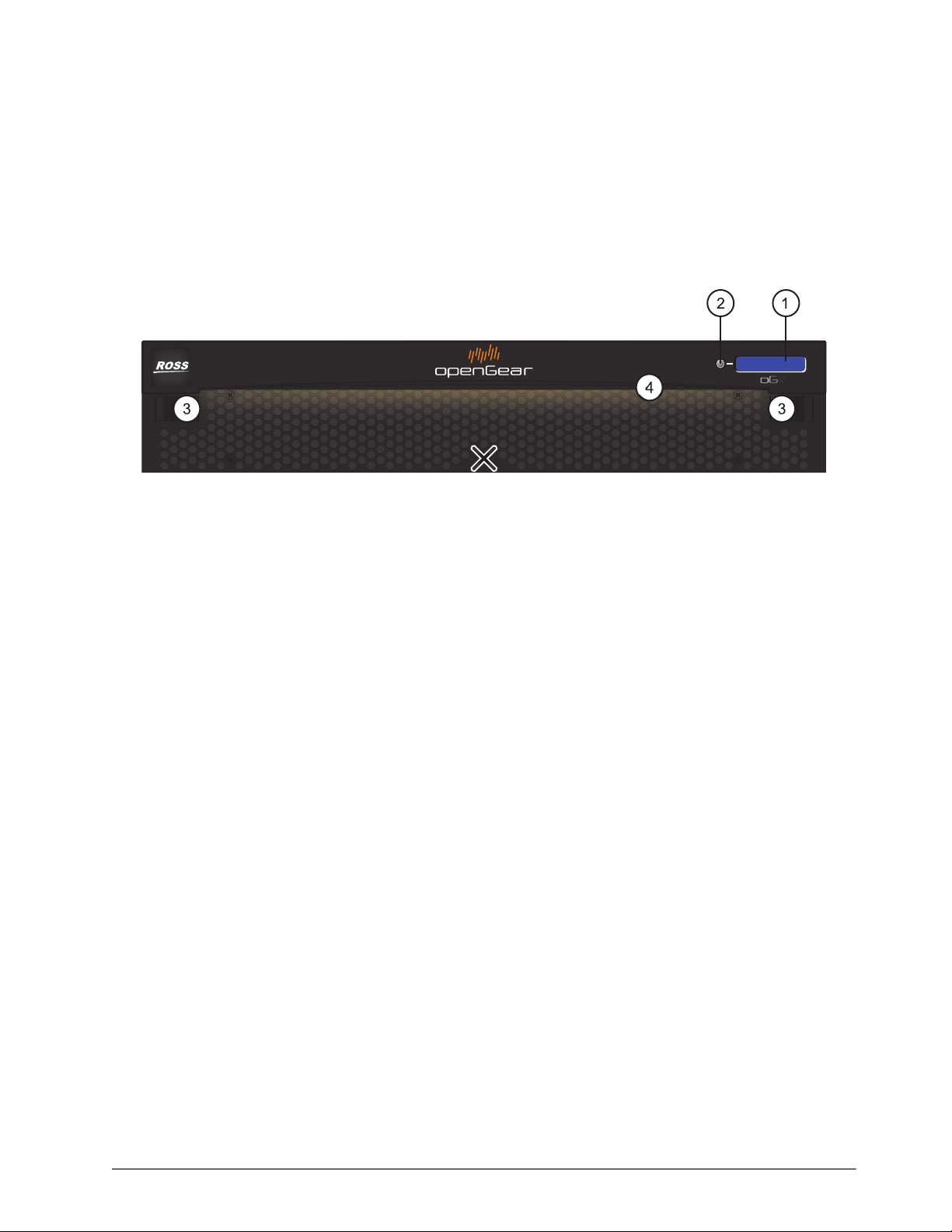
Figure 3.1 OGX-FR — Front Panel
1. Diagnostic Panel
The Diagnostic Panel is located on the frame front panel and enables you to quickly monitor the frame.
Information is presented in two separate lines of text:
› The top line in the display cycles through the name assigned to the frame in DashBoard and the current IP
address of the frame (or 0.0.0.0 if none available). The IP address is configured on the MFC-OG3-N Network
Controller Card. Refer to the user guide for your card to learn more about setting the IP address and frame
name in DashBoard.
› The second line reports errors or alarm conditions from any source. This includes fan failure alarms, power
supply warnings, or errors reported by the cards installed in the frame. The Diagnostic Panel organizes the
messages starting with the most recent at the top of the list. Refer to the user guide for your openGear card to
learn more about the types of error conditions that your card reports.
2. Toggle Button
The
Toggle button is located directly to the left of the Diagnostic Panel and enables you to mute the audio alarm,
or quickly scroll through the error messages reported on the second line of the Diagnostic Panel.
› Pressing the
› Pressing the
Tog gle button once mutes the audio alarm.
Tog gle button multiple times scrolls through the messages.
If you are scrolling through the list and a new error condition is reported, the list is automatically updated and
returns you to the beginning of the list.
3. Door Tabs
These tabs enable you to open the frame door and gain access to the interior of the frame. An alarm is raised
when the frame door is opened longer than 5 minutes.
4. Frame Glow
This feature is a user-programmable frame glow that can be configured to glow a preset color, or customized
colors to indicate different alarms. This is also useful when trying to locate the frame within a rack room. Refer
to the MFC-OG3-N and MFC-8322-S User Guide for details on configuring this feature.
OGX-FR Series User Guide (v1.0) Hardware Overview • 13
Page 14
OGX-FR Interior
ON
STAT
ON
STAT
This section briefly summarizes the features of the interior of the OGX-FR chassis.
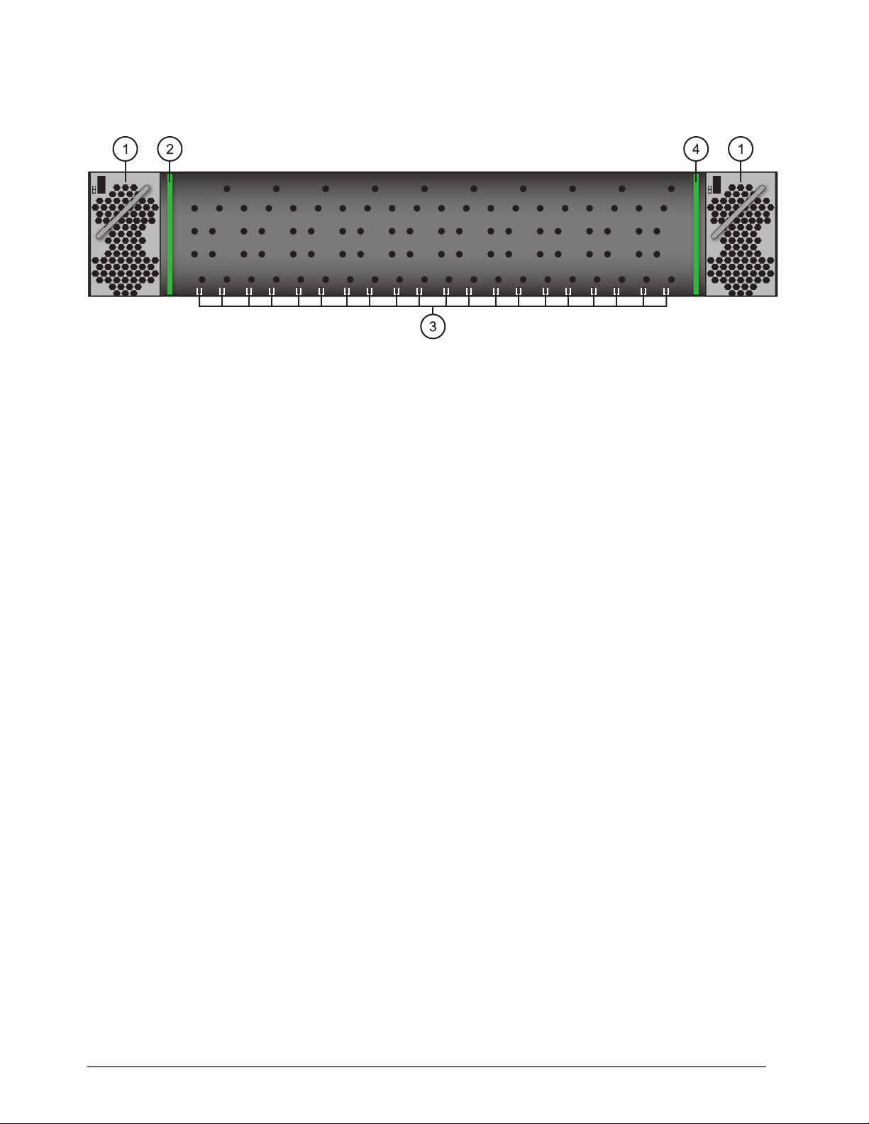
Figure 3.2 OGX-FR — Interior Features with Door Removed
1. Power Supplies
The OGX-FR frame can accommodate two front-loaded power supplies. However, each frame comes standard
with one power supply (the power supply on the left in Figure 3.2). Although a single power supply can fully
power a loaded frame, the addition of a second (optional) power supply gives the frame full power redundancy.
Each power supply is fed by a separate power cord, which is held in position to guard against accidental power
loss.
2. GFC-8322
The GFC-8322 comes pre-installed in the designated slot immediately to the right of PS1, and is secured with a
metal retaining latch. Its primary function is to distribute the reference signals to openGear cards installed in the
frame. Refer to the section “GFC-8322 Overview” on page 23 for more information.
3. Card Slots
There are a total of 20 card slots in the OGX-FR chassis and are used to install openGear cards into the chassis.
Depending on the card model and rear module you are using, multiple slots may be required. Refer to the user
guide for your openGear card for installation details for your card.
4. Controller Card
There are two models of Controller Card: MFC-8322-S and the MFC-OG3-N. The Controller Card comes
pre-installed in the OGX-FR frame. You must have the MFC-OG3-N installed in the OGX-FR frame to take
advantage of the Gigabit ethernet connectivity available for openGear cards in the frame. Refer to the
MFC-OG3-N User Guide for more information.
5. Mounted Fans (not shown)
The OGX-FR frames were designed with front-door mounted fans to provide forced air cooling for all cards, and
additional cooling for the power supplies. An intelligent fan controller adjusts fan speed with changes in frame
power loading. Particular attention has been paid to frame acoustics in order to keep fan noise to a minimum.
14 • Hardware Overview OGX-FR Series User Guide (v1.0)
Page 15

Rear Panel Overview
PS1
100-240V~50-60Hz 600W
CAUTION: RISK OF SHOCK
DO NOT OPEN
REF 1
LOOP
REF 2
LOOP
PS2
ETHERNET
100-240V~50-60Hz 600W
CAUTION
RISK OF SHOCK
DO NOT OPEN
OGX-FR
This section briefly summarizes the features of the OGX-FR rear panel.
Figure 3.3 OGX-FR — Rear Panel
1. PS1 Power Supply Connector
This connector is the AC Connector for the main power supply. Refer to the section “Connecting to a Power
Supply” on page 19 for more information.
2. PS2 Power Supply Connector
This connector is the AC Connector for the redundant power supply.
3. ETHERNET Communication Port
The Ethernet port is an RJ45 connector is used to connect the optional Network Controller card to an external
Ethernet network. This Network Controller card is required to bridge the external Ethernet network to the local
communication bus for monitoring and control of cards installed in the frame. Only cards with the
Communication bus interface will be able to be monitored and controlled this way.
The Ethernet port does not provide Power-over-Ethernet (PoE).
4. REF Connectors
Two sets of looping BNC inputs are provided to accept two independent reference signals supporting the
following reference signal types: Analog black, Tri-level sync, and AES/DARS reference.
5. Rear Modules for openGear Cards
The OGX-FR frame supports module-dependent rear modules. Rear modules can be ordered with cards, and are
easy and quick to install. Blank plates must be installed if the slots are not populated with openGear cards and
rear modules.
openGear Rear Modules
If your OGX-FR frame was ordered with cards requiring full rear modules or split rear modules, the appropriate
modules are installed at the factory or included with the cards.
Supports DFR-8321 and OG3-FR Rear Modules
The OGX-FR frame supports all existing rear modules designed for the DFR-8321 and OG3-FR frames. However,
rear modules designed for use in the OGX-FR frame are not compatible with other openGear frames.
OGX-FR Series User Guide (v1.0) Hardware Overview • 15
Page 16

Identifying an OGX-FR Rear Module
There are two ways to identify an OGX-FR frame rear module:
• the notched top of the rear module, and
• a small notch on the bottom left corner of the rear module that fits into a second seating slot on the midplane of
the OGX-FR frames. Note that this small notch is not present on other frame rear module types.
Caution — Attempting to install an OGX-FR frame rear module into an OG3-FR, DFR-8321,
DFR-8320, or DFR-8310 frame can damage the rear module.
Rear Module Types
This section provides an overview of the rear module types for your OGX-FR frame.
Full Rear Modules
The full rear modules features a single card connector and can include a combination of BNC, WECO™, fiber
optic, serial, and ethernet connectors. Each module occupies two slots in the frame and accommodates one card.
Ensure the openGear card is installed in the correct slot in the OGX-FR frame. Up to 10 cards can be installed in a
frame when using these modules.
Split Rear Modules
Much like the modules for the OG3-FR frames, split modules for the OGX-FR frame features two card connectors
and can have a combination of BNC, WECO™, fiber optic, serial, and ethernet connectors. Each card connector is
routed to a column of five BNCs. A split rear module occupies two slots in the OGX-FR frame but provides
connectors for two openGear cards, allowing you to install up to 20 cards in the frame.
Blank Rear Modules
Blank Rear Modules (R2-BLANK) are used when the slot does not have an openGear card installed. This helps to
ensure proper frame cooling and ventilation.
16 • Hardware Overview OGX-FR Series User Guide (v1.0)
Page 17

Physical Installation
If you have questions pertaining to the installation of OGX-FR, please contact us at the numbers listed in the section
“Contacting Technical Support”. Our technical staff is always available for consultation, training, or service.
For More Information on...
• the technical specifications for the OGX-FR, refer to the chapter “Technical Specifications” on page 35.
• installing an openGear card and its rear module in the OGX-FR frame, refer to the user guide for your openGear
card.
Before You Begin
The OGX-FR mounts in the rack frame by means of four rack screws fastened through the front mounting ears.
This should normally be sufficient to carry the load, including the weight of accompanying cables. However, in
certain applications such as mobile truck installations, it may be desirable to also support the rear of the frame. The
optional Rear Support Bars and Brackets are specifically engineered to compensate for extra load stress.
For More Information on...
• installing the brackets, refer to the section “Installing the Rear Support Bars and Brackets” on page 18.
• the frame dimensions, refer to Tab le 9 .1 on page 35.
Static Discharge
Throughout this chapter, please heed the following cautionary note:
ESD Susceptibility — Static discharge can cause serious damage to sensitive semiconductor
devices. Avoid handling circuit boards in high static environments such as carpeted areas and when
synthetic fiber clothing is worn. Always exercise proper grounding precautions when working on circuit
boards and related equipment.
Ventilation and Cooling
Your OGX-FR frame was specially engineered to minimize internal heat buildup and thus improve card reliability.
For More Information on...
• the power dissipation of individual openGear cards, refer to the user guide for your card.
• replacing the cooling fan module, refer to the section “Fan Filter Maintenance” on page 31.
Ventilation
For applications using less than 40W in a non-ventilated OGX-FR, but where the individual card power
consumption is greater than 8W, the cards should be evenly distributed in the frame. This will prevent the creation
of concentrated heat, or unbalanced heat-rise areas, in the frame.
Notice — For reliable performance, it is recommended that the OGX-FR frame door not be opened for
longer than 5 minutes on frames loaded with more than 40W. For some extra high power cards, the door
should not be open for more than 1 minute.
Cooling Fan Module
The OGX-FR frames come standard with a Cooling Fan Module installed in the frame door. The frame and
PS-OGX can supply up to a maximum of 500W of card power, with 15W per card. Under these ventilated
OGX-FR Series User Guide (v1.0) Physical Installation • 17
Page 18

conditions, there is no requirement for extra vertical spacing between the frames. The OGX-FR frames can be
Rack Mount Arm
Unlocked
Locked
PS2
ETHERNET
100-240V~50-60Hz 600W
CAUTION
RISK OF SHOCK
DO NOT OPEN
REF 1
LOOP
REF 2
LOOP
PS1
100-2
40V~
50-60
Hz 60
0W
CAUTION: RISK OF SHOCK
DO NOT OPEN
!
OGX-FR
!
!
stacked one on top of the other, a feature that is highly desirable in densely crowded rack frame environments.
Caution — The two sides of the OGX-FR frame have perforations that are needed to ventilate the
power supplies and must not be blocked.
Airflow Requirements
Under some conditions, the ambient air temperature inside rack-mount cabinets can be greater that the ambient
temperature within a room. For safe long term reliability, ensure the ambient air temperatures at the OGX-FR frame
front intake area are within the product’s specified operating temperature range. Adequate ventilation within a rack
frame must also be maintained. Ensure to adhere to the following clearance recommendations:
• Minimum 2” (5.08cm) clearance both right and left-hand side of the chassis sides with unrestricted vertical
airflow.
• Minimum 5” (12.7cm) clearance at the chassis rear with unrestricted vertical airflow.
Installation Requirements
Keep the following in mind when installing your OGX-FR frame:
• Install the frame for maximum stability during operation and in such a way as to allow adequate ventilation.
• The frame cannot be sealed in a closed container and must be installed in free air space where the ambient
temperature is monitored and controlled to not exceed 40°C (104°F) at the frame front door airflow intake.
• Ensure that adequate space exists in front and behind the frame and on both sides of the frame for airflow
exhaust.
• The location of the frame should be accessible, dry, and dust-free.
Installing the Rear Support Bars and Brackets
Under normal conditions, mounting the OGX-FR frame to the front of the rack with four rack screws should be
sufficient to carry the load, including the weight of accompanying cables.
To help reduce mechanical stress due to cable weight, the FSB-OGX rear support brackets are available for the
OGX-FR frame. The FSB-OGX are specifically engineered to compensate for extra load stress associated with
certain applications, such as mobile truck installations, to also support the rear of the OGX-FR frame.
Installing the FSB-OGX
This section describes how to attach the FSB-OGX rear support bars to a OGX-FR frame.
The FSB-OGX cannot be installed on the DFR-8321 or DFR-8310 frames.
To install the FSB-OGX
1. Attach the Rack Mount Arms of the FSB-OGX to the OGX-FR frame.
18 • Physical Installation OGX-FR Series User Guide (v1.0)
Page 19

2. Install the Rail Guides for each Rack Mount Arm.
INPUTS
12345
PSL
GPIO
TALLY
PS 2
PS 1
LTC
67
Rail Guide
Retaining
Bolts
Rack Mount
Arm
PS2
ETHERNET
100-240V~47-63Hz 450W
CAUTION
RISK OF SHOCK
DO NOT OPEN
!!
REF 1
LOOP
R
EF 2
LOOP
PS1
100-240V~50-60Hz 600W
CAUTION: RISK OF SHOCK
DO NOT OPEN
!
INPUTS
123
4
5
GPIO
TALLY
PS 2PS 1
LTC
67
5/16 Hex
Nuts
PS2
ETHERNET
100-240V~47-63Hz 450W
CAUTION
RISK OF SHOCK
DO NOT OPEN
!!
REF 1
LOOP
REF 2
LOOP
PS1
100-240V~50-60Hz 600W
CAUTION: RISK OF SHOCK
DO NOT OPEN
!
INPUTS
123
45
GPIO
TALLY
PS 2PS 1
LTC
6
7
Threaded
Rubber
Bumpers
PS2
ETHERNET
100-240V~47-63Hz 450W
CAUTION
RISK OF SHOCK
DO NOT OPEN
!!
REF 1
LOOP
REF 2
LOOP
PS1
100-240V~50-60Hz 600W
CAUTION: RISK OF SHOCK
DO NOT OPEN
!
3. Secure the Rail Guides and Rack Mount Arms to the rack.
4. Use the provided Threaded Rubber Bumpers to lock the Rack Mount Arms in place.
Connecting to a Power Supply
The OGX-FR comes standard with one power supply, with a second optional power supply (PS-OGX) available for
redundancy. For redundancy, and in applications where the equipment is used in a critical signal path, we
recommend that two power supplies be used in the OGX-FR. One A/C power cable has been provided with each
power supply ordered.
For further redundancy, each power cord should be connected to a separate power source for protection against
failure of the A/C power circuit. In the event of one power supply failure, the frame load is seamlessly transferred to
the other redundant power supply. Although the power supply is “hot-swappable” turning the power supply off
before inserting or removing it from the frame will increase the life span of the connectors.
OGX-FR Series User Guide (v1.0) Physical Installation • 19
Page 20

Power Supply Connectors (PSU1, PSU2)
PS1
100-240V~50-60Hz 600W
CAUTION: RISK OF SHOCK
DO NOT OPEN
!
REF 1
LOOP
REF 2
LOOP
PS2
ETHERNET
100-240V~50-60Hz 600W
CAUTION
RISK OF SHOCK
DO NOT OPEN
!
OGX-FR
To Redundant Power Supply To Main Power Supply
There are two power supply connectors located on the back of the OGX-FR:
• PSU1 — This connector is designated as the AC Connector for the first power supply.
• PSU2 — This connector is designated as the AC Connector for the second power supply.
Where the connectors are located is dependent on the frame you are using.
For More Information on...
• power supply locations in your OGX-FR, refer to the section “Rear Panel Overview” on page 15.
• installing the PS-OGX, refer to the section “Installing a Frame Power Supply” on page 31.
Power Cable Connection
This section includes information for connecting the power cables for the OGX-FR frame.
Warning Hazardous Voltages — The safe operation of this product requires that a protective
earth connection be provided. This protective earth is provided by the grounding conductor in the
equipment's supply cord. To reduce the risk of electrical shock to operator and service personnel, this
ground conductor must be connected to an earthed ground.
Warning — In some countries, it may be necessary to supply the correct mains supply cord. Use only
an approved IEC 320 C-13 type A/C line cord rated for a minimum 10A at 250V and certified for the
country of use.
To connect the power cables for an OGX-FR
1. Connect the cable’s female IEC connector to the frame socket marked PS 1.
2. If the Redundant Power Supply option is installed, plug the second IEC connector into PS 2.
Each AC connector includes a PowerLock, which is designed to retain the power cable connector.
3. Clip the PowerLock over the shoulder of the inserted AC cable end.
4. Connect the supplied power cable’s three-prong male connector to an AC outlet.
20 • Physical Installation OGX-FR Series User Guide (v1.0)
Page 21

Ethernet Cabling
The exact steps for connecting to your facility via an ethernet network depends on the network requirements of your
facility. Contact your IT Department before connecting to your facility network to ensure that there are no conflicts.
DashBoard uses the open SLP protocol to locate openGear frames on the network.
For More Information on...
• configuring the Network Controller card, refer to its user guide.
• installing and using DashBoard, refer to the DashBoard User Manual.
• the specifications for the OGX-FR, refer to the chapter “Technical Specifications” on page 35.
Cabling the Ethernet Port on the OGX-FR Frame
The Ethernet port is a standard 10/100/1000 RJ45 Ethernet connector and is used to exchange information with an
external monitoring, or control, system over an ethernet network. You must have the MFC-OG3-N installed in the
OGX-FR to take advantage of the Gigabit ethernet connectivity available for cards in the OGX-FR frame.
Required Pinouts
The Ethernet port has its RJ45 connector wired as a Network Interface Card (NIC). Ta bl e 5. 1 provides the wiring
information based on the type of Network Controller card installed in the OGX-FR frame.
Table 5.1 Ethernet Port Pinouts
MFC-8322-S
Pin Number
1 Tx+ TD1+
2Tx- TD1-
3 Rx+ TD2+
4* TD3+
5* TD3-
6 Rx- TD2-
7* TD4+
8* TD4-
* Shorted, 75ohm to Ground
(10/100 Ethernet)
Signal Signal
MFC-OG3-N
(10/100/1000 Ethernet)
Connecting to a Network
Use up to 328ft (100m) of CAT6 cable or better for Gigabit Ethernet network or use up to 328ft (100m) of CAT5
cable or better for 10/100Mbit Ethernet networks.
To connect the Ethernet port to a network
Connect the ETHERNET (RJ-45) port to the same network as your DashBoard client computer or to a network
that has a route to the network your DashBoard client computer is on.
1. Connect one free end of a straight through CAT5/5e/6 cable to a free port of the network hub.
2. Connect the other end of the same cable to the Ethernet port on the OGX-FR rear panel.
OGX-FR Series User Guide (v1.0) Ethernet Cabling • 21
Page 22

Figure 5.1 OGX-FR Frame — Ethernet Cabling
PS1
100-240V~50-60Hz 600W
CAUTION: RISK OF SHOCK
DO NOT OPEN
!
REF 1
LOOP
REF 2
LOOP
PS2
ETHERNET
100-240V~50-60Hz 450W
CAUTION
RISK OF SHOCK
DO NOT OPEN
!
To Ethernet Network
OGX-FR
22 • Ethernet Cabling OGX-FR Series User Guide (v1.0)
Page 23

Reference Cabling
PS1
100-240V~50-60Hz 600W
CAUTION: RISK OF SHOCK
DO NOT OPEN
!
REF 1
LOOP
REF 2
LOOP
PS2
ETHERNET
100-240V~50-60Hz 600W
CAUTION
RISK OF SHOCK
DO NOT OPEN
!
OGX-FR
To Reference Source 1
To Reference Source 2
The OGX-FR frame includes two independent looping reference BNCs (REF 1, REF 2) with connection to each
card slot. Each REF BNC accepts a single composite or tri-level sync signal to feed timing information to the
openGear cards installed in the frame.
GFC-8322 Overview
The GFC-8322 receives the analog reference signals driven to the REF 1 and REF 2 BNCs located on the rear
panel of OGX-FR frame. The GFC-8322 then distributes both reference signals to each of the 20 slots in the frame.
Frame settings such as the frame IP address, frame name, and the frame serial number are stored on the GFC-8322
via its Serial EEPROM.
Connecting a Video Reference Source
This feature distributes one or two reference signals to all cards in the OGX-FR frame. Cards which need an
external reference use this master reference signal in place of taking the signal from one of the card BNCs. This
provides for ease of installation and reduction in reference cabling requirements.
Connecting to a Reference Source
If only one reference type is required for the OGX-FR frame, connect it to the REF 1 BNC. Two reference types
enables you to use reference sources with a different signal formats, each via a separate REF BNC.
For More Information on...
• on specifying the analog reference source for your openGear card, refer to its user guide.
To connect a reference source to the OGX-FR
1. Connect one end of a Belden cable to the REF 1 BNC on the OGX-FR rear panel.
2. Connect the other end of the same Belden cable to the applicable output port on the external reference source
device.
Figure 6.1 OGX-FR — Reference Input Cabling
3. If the reference is not being looped to another device, ensure that the REF 1 LOOP BNC is terminated with a
75ohm terminator.
4. Repeat steps 1-3 for REF 2 if a second reference source is required.
Looping the Reference Signals
Use this procedure if you have multiple frames that will switch simultaneously.
OGX-FR Series User Guide (v1.0) Reference Cabling • 23
Page 24

To loop a reference signal
1. Connect the REF 1 LOOP BNC on the rear panel of the first frame to the REF 1 IN BNC on the rear panel of
the next frame using a 75ohm coaxial cable.
2. Continue looping the REF connectors across the frames that you want reference to this signal.
3. Ensure that the last frame in the video referencing loop has a 75ohm termination connected to its REF 2 IN
BNC.
Troubleshooting
During normal operation, the GFC-8322 must never be removed from the OGX-FR frame. To ensure this, the metal
retaining latch located on the front of the GFC-8322 must be engaged (pushed down) to prevent accidental removal
of the GFC-8322 from its slot.
Verify that the GFC-8322 is properly seated in its slot and the retaining latch is engaged when troubleshooting any
of the following conditions:
• reference signals are unavailable to the cards installed in the OGX-FR frame
• loss of network connection or the network settings for the OGX-FR frame were reset to the default values
24 • Reference Cabling OGX-FR Series User Guide (v1.0)
Page 25

Using DashBoard
This chapter provides instructions for launching DashBoard, displaying the OGX-FR in the Tree View of
DashBoard, and accessing the interfaces for the openGear cards installed in your frame.
Overview
Each OGX-FR frame reports the openGear cards installed in its chassis as sub-nodes in DashBoard. Each openGear
card can be configured and monitored independently via its options in DashBoard.
Before you can access your openGear cards, you must first ensure the OGX-FR displays in DashBoard. There are
two methods for adding an OGX-FR frame to the Tree View in DashBoard:
• using the auto-connect feature or
• manually adding a frame by specifying the IP address of the frame.
Both methods are described in the following sections.
Launching DashBoard
DashBoard connects to the OGX-FR frame using a TCP/IP LAN connection.
DashBoard must run on a computer that has a physical wired ethernet connection. Wireless connections do not
allow device discovery.
For More Information on...
• downloading and installing the DashBoard client software, refer to the DashBoard User Manual.
To launch DashBoard
1. Ensure that DashBoard is installed on a PC connected to the same network as your OGX-FR frame.
2. Ensure that you are running the latest DashBoard software.
3. Launch DashBoard by double-clicking its icon on your computer desktop.
Using the Automatic Detection Feature
When DashBoard is launched, and the Automatic Discovery feature of DashBoard is enabled, the OGX-FR frame is
automatically discovered and is available in the Tree View.
By default, DashBoard auto-detects any OGX-FR frame on the same IP subnet. How often DashBoard queries the
network for new OGX-FR frames (the default is every 10 seconds) depends on how the Automatic Detection
feature is configured in the Preferences menu of the DashBoard client.
Manually Adding OGX-FR Frames to DashBoard
You must add OGX-FR frames to the Tree View manually when the frame is on a different subnet from your
computer running the DashBoard client.
To manually add an OGX-FR frame to a DashBoard Tree View
1. Click from the Tree View toolbar.
The Select Equipment or Service Type to Add dialog opens.
2. Expand the openGear / DashBoard Connect node.
3. Select TCP/IP DashBoard Connect or openGear Device.
OGX-FR Series User Guide (v1.0) Using DashBoard • 25
Page 26
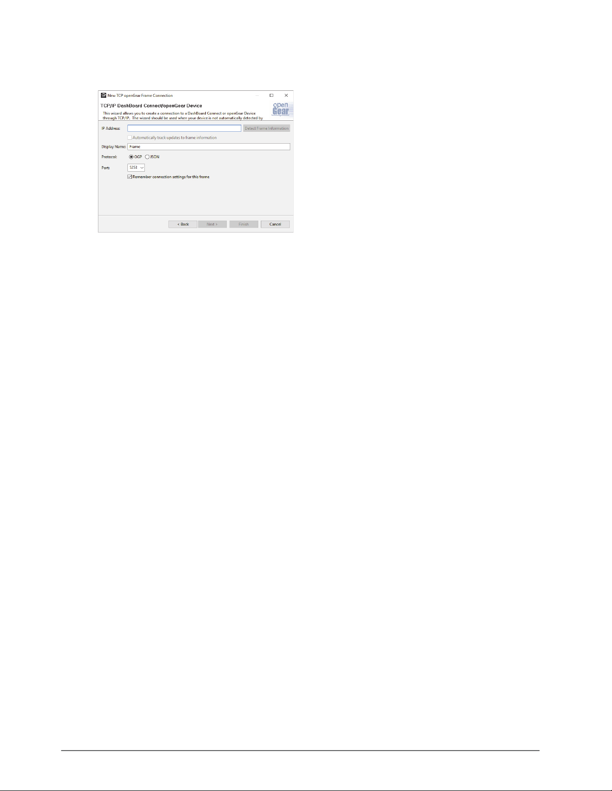
4. Click Next >.
The New TCP openGear Frame Connection dialog opens.
5. In the IP Address box, type the IP address of the OGX-FR frame.
To request that DashBoard detect the frame properties automatically
1. Click Detect Frame Information.
2. Verify that DashBoard retrieves the correct port, name, unique identifier, and other connection information
from the specified IP address.
3. Verify that the Automatically Track Updates to Frame Information box is selected so that any changes are
automatically updated in DashBoard.
To specify frame properties manually
1. Type the name of the OGX-FR frame, as you want it to appear in DashBoard.
2. From the Protocol options select
OGP (openGear Protocol).
3. Use the Port field to specify the port used for communication.
4. Select the Remember connection settings for this frame box to retain the settings.
5. Click
Finish to display the OGX-FR frame in the Tree View.
OGX-FR frames added to the Tree View are also displayed in the Advanced Tree View.
6. Repeat the procedure for each OGX-FR frame that you wish to add to the Tree View.
Re-naming the OGX-FR Frame in the Tree View
Once your OGX-FR frame displays in DashBoard, you may wish to provide a unique display name for the frame
for easier identification in the Tree View. There are two methods for re-naming an OGX-FR frame in DashBoard
depending on how you added the frame to the Tree View in DashBoard. The first method is for frames manually
added to the Tree View. The second method describes how to re-name an auto-detected frame using the DashBoard
menu options available on the Network Controller Card. Both methods are described below.
To re-name a manually added OGX-FR frame
1. Right-click the OGX-FR frame you wish to rename.
2. Select Rename Frame.
3. Enter the new name for the OGX-FR frame in the text field provided.
To re-name an auto-detected OGX-FR frame
1. Right-click the OGX-FR frame you wish to rename.
2. Select
26 • Using DashBoard OGX-FR Series User Guide (v1.0)
Open.
Page 27

The interface for the Network Controller Card displays in the DashBoard window.
In the following example, the interface for an MFC-OG3-N displays.
3. Select the Network tab.
4. Enter a new name for the OGX-FR frame in the Frame Name field.
5. Press
6. Click
Enter.
Apply.
Removing an OGX-FR Frame from the Tree View in DashBoard
This section outlines how to remove an OGX-FR frame from a Tree View in DashBoard. Once a frame is removed,
DashBoard no longer reports the status in the Tree View and you are no longer able to monitor or control the
affected devices. If communication with a frame is disconnected via the Disconnect option, the status indicator is
light gray until the frame is re-connected. If the status indicator is dark gray, with the rest of the node displaying as
normal, a connection cannot currently be established to the device.
If the OGX-FR frame you are removing is in a Custom Folder, you must first delete the frame from the Custom
Folder before it can be removed from the Tree View.
To remove an OGX-FR frame from the Tree View
1. Right-click the OGX-FR frame you wish to remove.
2. Select to remove the OGX-FR frame from the Tree View.
To disconnect an OGX-FR frame from the Tree View
1. Toggle to off.
2. Right-click the OGX-FR frame status indicator.
3. Select or toggle to on.
OGX-FR Series User Guide (v1.0) Using DashBoard • 27
Page 28

Auto-Discovery
Selecting for an auto-detected OGX-FR frame will temporarily remove the frame but the frame will re-appear in
the Tree View again due to the auto-discovery feature of DashBoard. You must first disable the auto-discovery
feature before you can remove a frame in this instance. Refer to the DashBoard User Manual for details on
configuring the auto-discovery feature.
You can still disconnect from an auto-discovered frame by toggling the Automatic Discovery option off.
Using DashBoard to Access openGear Cards in the OGX-FR Frame
The OGX-FR frame displays in DashBoard as a main node in the Tree View with a series of sub-nodes. Each
sub-node represents an openGear card installed in that frame.
For More Information on...
• available menus and parameters for your openGear card, refer to the user guide for your card.
To access an openGear card in DashBoard
1. Locate the OGX-FR frame in DashBoard.
2. Expand the OGX-FR frame node.
A list of sub-nodes displays in the Tree View.
3. Double-click an openGear card node to displays its interface in DashBoard.
In the example below, the DMX-8259-B was selected.
28 • Using DashBoard OGX-FR Series User Guide (v1.0)
Page 29

4. If your openGear card has multiple interfaces:
a. Expand the openGear card node.
b. Double-click a sub-node to display that interface in the DashBoard window.
In the example below, the Configuration interface for an MC1-MK is displayed.
OGX-FR Series User Guide (v1.0) Using DashBoard • 29
Page 30

30 • Using DashBoard OGX-FR Series User Guide (v1.0)
Page 31

Maintenance
This chapter summarizes maintenance tasks such as installing a new frame power supply, cleaning the frame air
filter, and replacing the Cooling Fan Module.
Installing a Frame Power Supply
The PS-OGX is a power factor corrected supply, capable of working with all world AC standards (100-240V). Each
supply has an indicator LED on its front panel, and an error detection circuit that monitors the power supply
operation.
The PS-OGX power supply installs on the right or left side of the OGX-FR chassis.
To install the power supply
1. Carefully unpack the power supply from its box, and retain all packing material for future use, if required.
2. Align the power supply into an unused power slot on the side of the frame.
3. Push the power supply in firmly to ensure a tight connection at the rear of the frame.
Fan Filter Maintenance
Routine maintenance of the fan filter installed in the OGX-FR is highly recommended to ensure proper airflow
through the chassis.
Cleaning the Frame Air Filter
The OGX-FR has a single air filter that is used to prevent dust and airborne particulates from contaminating the
frame. This filter should be cleaned at least once a year; but may need to be cleaned more frequently in some
environments.
To remove the air filter from the frame door
1. Locate the four 3/16”screws (#850-091R) on the frame door faceplate. (Figure 8.1)
10.xx.x.xx
1234
Slot 4 Error
Figure 8.1 OGX-FR — Screw Locations on Front Panel
2. Using a Phillips screwdriver, remove the four screws that secure the faceplate. Set the screws aside.
3. Ensure that the side door tabs are disengaged from the door.
4. Remove the faceplate by gently pulling it towards you while avoiding the Diagnostic Panel, the
and the STATUS LED.
5. Gently remove the air filter off the metal protective screen that separates the filter from the fans.
OGX-FR Series User Guide (v1.0) Maintenance • 31
Toggle button,
Page 32

To clean the air filter
1. Brush any loose dust off of the filter.
2. Place the filter under warm running water to remove any remaining dust. On one side of the filter is a foam
filter material. When rinsing, water should flow out of this side.
3. Remove the filter from the water and thoroughly pat dry with a towel to remove any moisture.
To replace the clean, dry filter into the frame door
1. Place the clean air filter across the metal protective screen, orienting it in the same position you found it in
during step 1 of the procedure “To remove the air filter from the frame door”.
2. Install the faceplate by gently fitting it back onto the frame door, ensuring the faceplate does not interfere with
the Diagnostic Panel, the
Tog gle button, and the STATUS LED.
3. Verify that the side door tabs are seated properly in the cutouts on the frame door bracket.
4. Using a Phillips screwdriver, secure the faceplate using the four screws removed during step 2 of the procedure
“To remove the air filter from the frame door”.
Replacing the Frame Air Filter
Order the Air Filter Replacement Kit (AFK-OGX) from your openGear sales representative before replacing the
frame air filter in your OGX-FR frame.
To remove the old air filter from the frame door
1. Using a Phillips screwdriver, remove the four 3/16”screws (#850-091R) screws that secure the faceplate. Set
the screws aside. (Figure 8.2)
10.xx.x.xx
1234
Slot 4 Error
Figure 8.2 OGX-FR — Screw Locations on Front Panel
2. Ensure that the side door tabs are disengaged from the door.
3. Remove the faceplate by gently pulling it towards you while avoiding the Diagnostic Panel, the
Toggle button,
and the STATUS LED.
4. Gently remove the air filter off the metal protective screen that separates the filter from the fans.
To install the new filter into the frame door
1. Place the new air filter across the metal protective screen, orienting it in the same position you found it in
during step 1 of the procedure “To remove the old air filter from the frame door”.
2. Install the faceplate by gently fitting it back onto the frame door, ensuring the faceplate does not interfere with
the Diagnostic Panel, the
Tog gle button, and the STATUS LED on the frame door.
3. Verify that the side door tabs are seated properly in the cutouts on the frame door bracket.
4. Using a Phillips screwdriver, secure the faceplate using the four screws removed during step 1 of the procedure
“To remove the old air filter from the frame door”.
32 • Maintenance OGX-FR Series User Guide (v1.0)
Page 33

Replacing the Cooling Fan Module
The Cooling Fan Module is installed in the OGX-FR door. To replace a failed Cooling Fan Module, you need to
replace the entire frame door.
Contact your openGear sales representative to order a Cooling Fan Module Replacement Kit (CFM-OGX).
Replacing the OGX-FR Door
The CFM-OGX includes the fan board and filter pre-installed in a new OGX-FR frame door. You will need to
remove the old door from your OGX-FR frame and replace it with the new door.
To remove the old door from the OGX-FR frame
1. Gently pull the side door tabs towards the center of the door, releasing the door from the frame.
The door extender arms retain the door to the chassis.
2. Using both hands, pull the door towards you.
3. Tilt the door upward until the extender arms match the cutout for the retaining bolts.
4. Gently push the door extender arms in and over the retaining bolts and unhook from the frame.
5. Remove the door and place it on a clean, flat, static-free surface.
To install the new door in the frame
1. Using both hands, with the door tilted up, slide the new door into the frame while pushing the extender arms in
and over the retaining bolts.
2. Pull and release the door tabs to ensure the:
• frame door is securely locked to the OGX-FR frame, and
• the tabs latch into the frame.
OGX-FR Series User Guide (v1.0) Maintenance • 33
Page 34

34 • Maintenance OGX-FR Series User Guide (v1.0)
Page 35

Technical Specifications
This chapter provides technical information for OGX-FR.
Specifications are subject to change without notice.
Dimensions
Table 9.1 Technical Specifications — Chassis Dimensions
Item Specifications
Number of RU 2
Height 3.5” (8.89cm)
Width 19” (48.26cm)
Depth 17.7” (45cm)
Weight (two PS-OGX installed) 20lb (9.07kg)
PS-OGX
Table 9.2 Technical Specifications — Power
Input 6.3A (650W)
Output 1 12V 41.6A, 500W maximum
Output 2 -7.5V 5A, 37.5W maximum
Total Sum of both outputs not to exceed 500W
Card Slots
Number of Slots 20
Total Power Available 450W
Maximum Card Power
High-density (Split) Rear Module
Standard Rear Module
Double-wide Rear Module
a. Accommodates two openGear cards and requires two slots in the frame chassis.
b. Accommodates one openGear card and requires two slots in the frame chassis.
c. Or 45W if the openGear card has integrated cooling.
d. Accommodates one or two openGear cards and requires four slots in the frame chassis.
e. Or 75W for a single card with integrated cooling.
f. Or 90W for a multi-slot assembly with integrated cooling and receiving power from two or more midplane
Item Specifications
Table 9.3 Technical Specifications — Card Slots
Item Specifications
a
15W per card
connectors.
b
d
30W per card
60W per assembly
c
e,f
OGX-FR Series User Guide (v1.0) Technical Specifications • 35
Page 36

Frame Controller and Fans
Table 9.4 Technical Specifications — Frame Controller and Fans
Item Specifications
Max. Power: +12V Rail 4A, 48W
Max. Power: -7.5V Rail 0.2A (1.5W)
Total 50W maximum
GFC-8322
Table 9.5 Technical Specifications — GFC-8322
Item Specifications
Max. Power: +12V Rail 0.2A (2.4W)
Max. Power: -7.5V Rail 0.2A (1.5W)
Total 3.9W maximum
Reference Inputs
Table 9.6 Technical Specifications — Reference Inputs
Number of Inputs 2 looping
Level 1Vpp nominal
Signal
Impedance 75ohm terminating
Return Loss >30dB to 30MHz
Maximum DC on REF Input ±1V
Environment
Maximum Ambient Temperature 0°C to 40°C (32°F to 104°F)
Humidity, non-condensing <95%
Item Specifications
Analog video sync (black burst or tri-level), or AES/EBU
DARS
Table 9.7 Technical Specifications — Environment
Item Specifications
36 • Technical Specifications OGX-FR Series User Guide (v1.0)
Page 37

Service Information
Routine maintenance to this openGear product is not required. In the event of problems with your card, the
following basic troubleshooting checklist may help identify the source of the problem. If the frame still does not
appear to be working properly after checking all possible causes, please contact your openGear products distributor,
or the Technical Support department at the numbers listed under the “Contacting Technical Support” on page 10.
1. Visual Review — Performing a quick visual check may reveal many problems, such as connectors not
properly seated or loose cables. Check the card, the frame, and any associated peripheral equipment for signs of
trouble.
2. Power Check — Inspect the power indicator LED on the distribution frame front panel for the presence of
power. If the power LED is not illuminated, verify that the power cable is connected to a power source and that
power is available at the power main. Confirm that the power supplies are fully seated in their slots. If the
power LED is still not illuminated, replace the power supply with one that is verified to work.
3. Input Signal Status — Verify that source equipment is operating correctly and that a valid signal is being
supplied.
4. Output Signal Path — Verify that destination equipment is operating correctly and receiving a valid signal.
5. Unit Exchange — Exchanging a suspect unit with a unit that is known to be working correctly is an efficient
method for localizing problems to individual units.
Warranty and Repair Policy
The OGX-FR frame is warranted to be free of any defect with respect to performance, quality, reliability, and
workmanship for a period of FIVE (5) years from the date of shipment from our factory. In the event that your
OGX-FR frame proves to be defective in any way during this warranty period, Ross Video Limited reserves the
right to repair or replace this piece of equipment with a unit of equal or superior performance characteristics.
Should you find that this OGX-FR frame has failed after your warranty period has expired, we will repair your
defective product should suitable replacement components be available. You, the owner, will bear any labor and/or
part costs incurred in the repair or refurbishment of said equipment beyond the FIVE (5) year warranty period.
In no event shall Ross Video Limited be liable for direct, indirect, special, incidental, or consequential damages
(including loss of profits) incurred by the use of this product. Implied warranties are expressly limited to the
duration of this warranty.
This User Manual provides all pertinent information for the safe installation and operation of your OGX-FR frame.
Ross Video policy dictates that all repairs to the OGX-FR frame are to be conducted only by an authorized Ross
Video Limited factory representative. Therefore, any unauthorized attempt to repair this product, by anyone other
than an authorized Ross Video Limited factory representative, will automatically void the warranty. Please contact
Ross Video Technical Support for more information.
In Case of Problems
Should any problem arise with your OGX-FR frame, please contact the Ross Video Technical Support Department.
(Contact information is supplied at the end of this publication.)
A Return Material Authorization number (RMA) will be issued to you, as well as specific shipping instructions,
should you wish our factory to repair your OGX-FR frame. If required, a temporary replacement frame will be
made available at a nominal charge. Any shipping costs incurred will be the responsibility of you, the customer. All
products shipped to you from Ross Video Limited will be shipped collect.
The Ross Video Technical Support Department will continue to provide advice on any product manufactured by
Ross Video Limited, beyond the warranty period without charge, for the life of the equipment.
OGX-FR Series User Guide (v1.0) Service Information • 37
Page 38

38 • Service Information OGX-FR Series User Guide (v1.0)
Page 39

Glossary
The following terms are used throughout this guide:
Active image — the portion of the video picture area (production aperture) that is being utilized for output content.
Active image excludes letterbox bars and pillarbox bars.
Card — openGear terminal devices within openGear frames, including all components and switches.
CBR — constant bit rate.
CDN — content distribution network.
DashBoard — the DashBoard Control System.
DF — Differentiated Services.
DTVCC captions — CEA-708 captions.
Frame — the OGX-FR frame that houses the OGX-FR.
HLS — HTTP Live streaming.
HTTP — Direct Hypertext Transfer Protocol.
MIB — management information base.
Network Controller Card — the MFC-OG3-N and any available options unless otherwise noted.
NTSC captions — the CEA-608-D: Line 21 Data Services captions.
openGear frame — refers to the OGX-FR frames unless otherwise noted.
PAL — PAL-B and PAL-G unless otherwise stated.
PCR — program clock reference.
PID — packet identifier.
Production aperture — the image lattice that represents the maximum possible image extent in a given standard
(e.g. the full size of all active pixels and active lines). For example, the 1080i production aperture would be
1920x1080.
RTMP — Real Time Messaging Protocol.
Stream — a transport stream present at the port.
System— the mix of interconnected production and terminal equipment in your environment.
TCP — Transmission Control Protocol.
TOS — Type of Service.
TPG — Test Packet Generator.
TTL — Time To Live.
UDP — User Datagram Protocol.
User — the person who uses the OGX-FR.
OGX-FR Series User Guide (v1.0) Glossary • 39
Page 40

40 • Glossary OGX-FR Series User Guide (v1.0)
 Loading...