

Page 1
NK-VRC User Guide
Page 2

Thank You for Choosing Ross
You've made a great choice. We expect you will be very happy with your purchase of Ross Technology.
Our mission is to:
1. Provide a Superior Customer Experience
• offer the best product quality and support
2. Make Cool Practical Technology
• develop great products that customers love
Ross has become well known for the Ross Video Code of Ethics. It guides our interactions and
empowers our employees. I hope you enjoy reading it below.
If anything at all with your Ross experience does not live up to your expectations be sure to reach out to
us at solutions@rossvideo.com.
David Ross
CEO, Ross Video
dross@rossvideo.com
Ross Video Code of Ethics
Any company is the sum total of the people that make things happen. At Ross, our employees are a
special group. Our employees truly care about doing a great job and delivering a high quality customer
experience every day. This code of ethics hangs on the wall of all Ross Video locations to guide our
behavior:
1. We will always act in our customers’ best interest.
2. We will do our best to understand our customers’ requirements.
3. We will not ship crap.
4. We will be great to work with.
5. We will do something extra for our customers, as an apology, when something big goes wrong and
it's our fault.
6. We will keep our promises.
7. We will treat the competition with respect.
8. We will cooperate with and help other friendly companies.
9. We will go above and beyond in times of crisis. If there's no one to authorize the required action in
times of company or customer crisis - do what you know in your heart is right. (You may rent
helicopters if necessary.)
Page 3

NK-VRC · User Guide
• Ross Part Number: 9807DR-1009-05
• Release Date: December 4, 2017.
The information contained in this Guide is subject to change without notice or obligation.
Copyright
©2017 Ross Video Limited, Ross®, and any related marks are trademarks or registered trademarks of Ross Video
Limited. All other trademarks are the property of their respective companies. PATENTS ISSUED and PENDING.
All rights reserved. No part of this publication may be reproduced, stored in a retrieval system, or transmitted in any
form or by any means, mechanical, photocopying, recording or otherwise, without the prior written permission of
Ross Video. While every precaution has been taken in the preparation of this document, Ross Video assumes no
responsibility for errors or omissions. Neither is any liability assumed for damages resulting from the use of the
information contained herein.
Patents
Patent numbers US 7,034,886; US 7,508,455; US 7,602,446; US 7,802,802 B2; US 7,834,886; US 7,914,332; US
8,307,284; US 8,407,374 B2; US 8,499,019 B2; US 8,519,949 B2; US 8,743,292 B2; GB 2,419,119 B; GB
2,447,380 B; and other patents pending.
Notice
The material in this manual is furnished for informational use only. It is subject to change without notice and should
not be construed as commitment by Ross Video Limited. Ross Video Limited assumes no responsibility or liability
for errors or inaccuracies that may appear in this manual.
Safety Notices
Refer to the “Important Regulatory and Safety Notices” document that accompanied your product.
Statement of Compliance
This product has been determined to be compliant with the applicable standards, regulations, and directives for the
countries where the product is marketed.
Compliance documentation, such as certification or Declaration of Compliance for the product is available upon
request by contacting techsupport@rossvideo.com. Please include the product; model number identifiers and serial
number and country that compliance information is needed in request.
EMC Notices
US FCC Part 15
This equipment has been tested and found to comply with the limits for a class A Digital device, pursuant to part 15
of the FCC Rules. These limits are designed to provide reasonable protection against harmful interference when the
equipment is operated in a Commercial environment. This equipment generates, uses, and can radiate radio
frequency energy and, if not installed and used in accordance with the instruction manual, may cause harmful
Page 4
interference to radio communications. Operation of this equipment in a residential area is likely to cause harmful
Type of Equipment User’s Guide
A
(߶הࡈ ؏ܞݦࢢ)
Class A Equipment
(Industrial Broadcasting &
Communication Equipment)
ࢇ Е ߶הࡈ(A) ࢷળࢶଢԻ۰ શ
ӖЕ یࡈЕ ࢇ ࢺࡶ ࣯ࢂଜݤ Ԃ
ֲ, ɼࢽ࠹ࢂ ࠇ߾۰ یࡈଜЕ ʨࡶ ּࢶࡳԻ
ଢТЬ.
This equipment is Industrial (Class A)
electromagnetic wave suitability equipment and
seller or user should take notice of it, and this
equipment is to be used in the places except for home.
interference in which case the user will be required to correct the interference at his own expense.
Notice — Changes or modifications to this equipment not expressly approved by Ross Video Limited
could void the user’s authority to operate this equipment.
Canada
This Class A device complies with Canadian ICES-003 rules.
Cet appariel numerique de la classe “A” est conforme a la norme NMB-003 du Canada.
European Union
This equipment is in compliance with the essential requirements and other relevant provisions established under
regulation (EC) No 765/2008 and Decision No 768/2008/EC referred to as the “New Legislative Framework”.
Warning — This equipment is compliant with Class A of CISPR 32. In a residential environment this
equipment may cause radio interference.
Australia/New Zealand
This equipment is in compliance with the provisions established under the Radiocommunications Act 1992 and
Radiocommunications Labeling (Electromagnetic Compatibility) Notice 2008.
Korea
This equipment is in compliance with the provisions established under the Radio Waves Act.
Class A equipment (Broadcasting and communications service for business use).
This device is a business-use (Class A) EMC-compliant device. The seller and user are advised to be aware of this
fact. This device is intended for use in areas outside home.
International
This equipment has been tested under the requirements of CISPR 22:2008 or CISPR 32:2015 and found to comply
with the limits for a Class A Digital device.
Notice — This is a Class A product. In domestic environments, this product may cause radio
interference, in which case the user may have to take adequate measures.
Warranty and Repair Policy
The product is backed by a comprehensive one-year warranty on all components.
If an item becomes defective within the warranty period Ross will repair or replace the defective item, as
determined solely by Ross.
Page 5

Warranty repairs will be conducted at Ross, with all shipping FOB Ross dock. If repairs are conducted at the
customer site, reasonable out-of-pocket charges will apply. At the discretion of Ross, and on a temporary loan basis,
plug in circuit boards or other replacement parts may be supplied free of charge while defective items undergo
repair. Return packing, shipping, and special handling costs are the responsibility of the customer.
This warranty is void if products are subjected to misuse, neglect, accident, improper installation or application, or
unauthorized modification.
In no event shall Ross Video Limited be liable for direct, indirect, special, incidental, or consequential damages
(including loss of profit). Implied warranties, including that of merchantability and fitness for a particular purpose,
are expressly limited to the duration of this warranty.
This warranty is TRANSFERABLE to subsequent owners, subject to Ross’ notification of change of ownership.
Extended Warranty
For customers that require a longer warranty period, Ross offers an extended warranty plan to extend the standard
warranty period by one year increments. For more information, contact your regional sales manager.
Environmental Information
The equipment may contain hazardous substances that could impact health and the environment.
To avoid the potential release of those substances into the environment and to diminish the need for the extraction
of natural resources, Ross Video encourages you to use the appropriate take-back systems. These systems will reuse
or recycle most of the materials from your end-of-life equipment in an environmentally friendly and health
conscious manner.
The crossed-out wheeled bin symbol invites you to use these systems.
If you need more information on the collection, reuse, and recycling systems, please contact your local or regional
waste administration. You can also contact Ross Video for more information on the environmental performances of
our products.
Page 6

Company Address
Ross Video Limited
8 John Street
Iroquois, Ontario
Canada, K0E 1K0
General Business Office:
Technical Support:
After Hours Emergency:
E-mail (Technical Support): techsupport@rossvideo.com
E-mail (General Information): solutions@rossvideo.com
Website: http://www.rossvideo.com
Ross Video Incorporated
P.O. Box 880
Ogdensburg, New York
USA 13669-0880
Fax:
(+1) 613
(+1) 613
(+1) 613
(+1) 613
652 4886
652 4425
652 4886
349 0006
Page 7

Contents
Introduction 9
Documentation Conventions.....................................................................................................................................9
Getting Started 11
Features and Components .......................................................................................................................................11
Typical System Equipment .....................................................................................................................................11
System Overview ....................................................................................................................................................11
Resource Management............................................................................................................................................13
Implementing Your System Plan ............................................................................................................................14
Communication Overview ....................................................................................................................................14
Physical Installation 15
Unpacking the Equipment....................................................................................................................................... 15
General....................................................................................................................................................................15
Hardware Overview ................................................................................................................................................15
Installing the NK-VRC into a Routing Switcher System ....................................................................................... 16
Connecting the NK-VRC to a Power Supply .........................................................................................................17
Checking the Software Version of the NK-VRC.................................................................................................... 17
Upgrading the NK-VRC Software.......................................................................................................................... 18
Setting Up the NK-VRC 19
Before You Begin ................................................................................................................................................... 19
Accessing the NK-VRC Interface in DashBoard....................................................................................................19
Connecting to the NK-IPS in the Routing Switcher System ..................................................................................20
NK-VRC Interface Overview ................................................................................................................................. 20
Sending the Configuration to a Device...................................................................................................................21
SmartPaste...............................................................................................................................................................22
Setting Up Virtual Routing ..................................................................................................................................... 23
Creating Labels for Virtual Sources and Destinations............................................................................................23
Mapping Physical Inputs/Outputs to Virtual Sources/Destinations and Defining Classes.....................................23
Configuring Resources............................................................................................................................................ 28
Configuring Park Sources ....................................................................................................................................... 29
Configuring Resource Rules ...................................................................................................................................29
Configuring Control Panel/Device Priorities..........................................................................................................30
Setting Up the Log for Diagnostics ........................................................................................................................31
Setting Up Carbonite eXtreme Compatibility.........................................................................................................31
Setting Up Machine Control ................................................................................................................................... 32
Saving the NK-VRC Configuration ........................................................................................................................32
Resource Management Setup Examples 33
Single Router Configuration ...................................................................................................................................33
Two Router Configuration......................................................................................................................................35
Operating the NK-VRC 37
General....................................................................................................................................................................37
Resource and Panel Priorities .................................................................................................................................37
LED Indicators........................................................................................................................................................ 37
Resource Usage.......................................................................................................................................................38
Resetting the NK-VRC ........................................................................................................................................... 38
Troubleshooting ......................................................................................................................................................39
Glossary 41
NK-VRC User Guide (v05) Contents • i
Page 8

ii • Contents NK-VRC User Guide (v05)
Page 9

Introduction
This guide is for system administrators, installers, and operators of the Ross Video NK-VRC. It provides
instructions on how to connect the NK-VRC to your routing switcher system, how to configure the NK-VRC using
DashBoard software, and how to operate it. It assumes that you are experienced with general broadcast concepts,
and that you are familiar with the planning requirements for a routing switcher system.
The following chapters are included:
•“Introduction” summarizes the guide and provides important terms, and conventions.
•“Getting Started” provides general information to keep in mind before configuring your NK-VRC within a
routing system.
•“Physical Installation” provides instructions for physically installing the NK-VRC.
•“Setting Up the NK-VRC” outlines basic tasks for setting up your NK-VRC.
•“Resource Management Setup Examples” provides an overview of resource management.
•“Operating the NK-VRC” provides general information on monitoring and troubleshooting the NK-VRC.
•“Glossary” provides a definitions of commonly used terms and conventions for this guide.
If you have questions pertaining to the operation of the NK-VRC, contact us at the numbers listed in the section
“Contacting Technical Support”. Our technical staff is always available for consultation, training, or service.
Documentation Conventions
Special text formats are used in this guide to identify parts of the user interface, text that a user must enter, or a
sequence of menus and sub-menus that must be followed to reach a particular command.
Interface Elements
Bold text is used to identify a user interface element such as a dialog box, menu item, or button. For example:
In the Save As dialog, click
OK.
User Entered Text
Courier text is used to identify text that a user must enter. For example:
In the Language box, enter
English.
Referenced Guides
Italic text is to identify the titles of referenced guides, manuals, or documents. For example:
For more information, refer to the DashBoard User Guide.
Menu Sequences
Menu arrows are used in procedures to identify a sequence of menu items that you must follow. For example, if a
step reads “File > Save As,” you would click the File menu and then click Save As.
Important Instructions
Star icons are used to identify important instructions or features. For example:
An error message displays when an object overlaps a tile or when one tile overlaps another in the workspace.
NK-VRC User Guide (v05) Introduction • 9
Page 10

Contacting Technical Support
At Ross Video, we take pride in the quality of our products, but if problems occur, help is as close as the nearest
telephone.
Our 24-hour Hot Line service ensures you have access to technical expertise around the clock. After-sales service
and technical support is provided directly by Ross Video personnel. During business hours (Eastern Time),
technical support personnel are available by telephone. After hours and on weekends, a direct emergency technical
support phone line is available. If the technical support person who is on call does not answer this line immediately,
a voice message can be left and the call will be returned shortly. This team of highly trained staff is available to
react to any problem and to do whatever is necessary to ensure customer satisfaction.
• Technical Support: (+1) 613-652-4886
• After Hours Emergency: (+1) 613-349-0006
• E-mail: techsupport@rossvideo.com
• Web site: http://www.rossvideo.com
10 • Introduction NK-VRC User Guide (v05)
Page 11

Getting Started
The NK-VRC Virtual Routing Core provides virtual routing and resource management capability to an NK Series
routing switcher system.
Features and Components
The NK-VRC provides the following features:
• virtual routing for a complex NK Series routing switcher system
• up to 1000 virtual source mappings to physical inputs
• up to 1000 virtual destination mappings to physical outputs
• resource management
• four status LEDs for status/error indications
• compact 1 RU design
• software is fully upgradeable using DashBoard.
• slim modular design integrates with NK Series devices via T-Bus using straight CAT5 Ethernet cables
Typical System Equipment
The NK-VRC is used when you require virtual routing or resource management. Using DashBoard, you can map
inputs and outputs from routing switchers through to the NK-VRC for control via any remote control panel. These
parameters can be saved in a configuration file (.cbd) and sent to an NK-VRC at any time using DashBoard. The
SmartPaste function can also be used to quickly duplicate a configuration file or device configuration to another
device. Therefore, if an NK-VRC is used in a number of different operating scenarios, the configuration can be
changed easily and quickly.
Typical equipment in an NK Series routing switcher system where an NK-VRC would be used includes:
• one or more NK Series routing switchers
• an NK-IPS Network Bridge
• control panels and devices (i.e. RCP-NKM, RCP-NKQ, NK-3RD)
• a PC running DashBoard
• standard source and destination equipment (i.e. cameras, VTRs, servers)
• optionally, one or more external resources (i.e. openGear DA card, GearLite up-converter)
If you are connecting the PC directly to the NK-IPS, use a crossover CAT5 Ethernet cable.
If you are connecting the PC indirectly via an Ethernet switch to the NK-IPS, use a straight-through CAT5
Ethernet cable.
The NK-IPS and PC with DashBoard are only required for setting up the configuration file, then sending this to
the device. However, you can use the NK Switchboard feature in DashBoard to control and monitor a routing
switcher system.
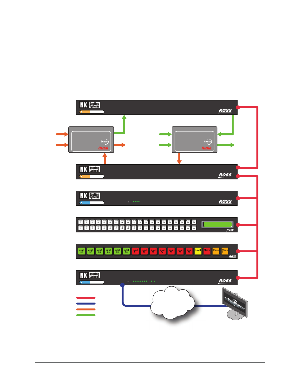
System Overview
A routing switcher system may use distributed control across the Internet, a LAN, or a VPN. The routing switcher
system shown in Figure 2.1 has been simplified. The NK-VRC enables you to map physical inputs and outputs
across multiple router levels to a virtual source or destination. For example, in Figure 2.1, Camera 1 provides
inputs to the SDI router level and the AES/EBU router level. If you map these two inputs to the same virtual source
(call this Camera 1), you can switch both levels with a single switch request. Without virtual routing, this can be
NK-VRC User Guide (v05) Getting Started • 11
Page 12

achieved with breakaways, but only if all routers have their inputs and outputs mapped 1:1. This is a simple
Ethernet Communication
T-Bus Communication (via CAT5 straight-through cables)
Router Inputs
Router Outputs
NK-IPS
Network Bridge
ETHERNET
POWER
Service
Port
T-BUS
NK-VRC
Virtual Routing Core
POWER
T-BUS
RCP-NKQ
Remote Control Panel
PSU
T-BUS
NK-3G64
64X64 3G/HD/SD SDI Router
VIDREF
T-BUS
NK-D32-75
AES/EBU Digital Audio Router
VID REF
25 26 27 28 29 30 31 32
17 18 19 20 21 22 23 24
INPUTS
9 10 11 12 13 14 15 16
1 2 3 4 5 6 7 8
25 26 27 28 29 30 31 32
17 18 19 20 21 22 23 24
9 10 11 12 13 14 15 16
1 2 3 4 5 6 7 8
OUTPUTS
T-BUS
Network Switch
PORT 2 PORT 3 PORT 4 PORT 5 PORT 6 PORT 7 PORT 8PORT 1
PC running DashBoard
Internet / LAN / VPN
Server 1
Camera 2
Server 3
Monitor
VTR 2
Camera 1
Virtual SRC 1
Virtual SRC 2
Virtual SRC 3
Server 2
Virtual SRC 4
VTR 1
Virtual SRC 5
Virtual DEST 1
Virtual DEST 2
Virtual DEST 3
Appropriate NK Series
Power Supply
Appropriate NK Series
Power Supply
Appropriate NK Series
Power Supply
Appropriate NK Series
Power Supply
Appropriate NK Series
Power Supply
example of virtual routing. You can build up a complex map of several different physical devices that become one
virtual device. When a switch request is made for a virtual device, all the physical devices that are mapped to the
virtual device are switched.
Figure 2.1 Layout showing a simplified routing switcher system with an NK-VRC
When changes are made to the configuration of a device, the changes are not activated in the device until the
configuration file containing the changes is sent to the device. You can save a configuration file, but it will not be
loaded to the device until it is sent to the device. Once a configuration file has been sent to the device, the NK-VRC
operates transparently, mapping virtual switch requests from a remote control panel to physical switch requests for
the routing switchers.
12 • Getting Started NK-VRC User Guide (v05)
Page 13
Resource Management
Resource management is a function of a router control system that enables routing of signals between different
router types (such as analog and digital). This is done by using resources to convert from one format to another
(such as an analog to digital converter).
Resource management simplifies the operation of a router system by routing signals through a resource from one
router to another, without requiring the user to know which source and destination to which the resource is
connected. Once configured, the system will be able to automatically find the path between routers. Another
application for resource management is when a limited number of tie lines are to be shared between routers.
Multiple resources can be managed to enable more than one signal path between routers.
Analog
SRC
Analog
Silence
NK-D16 AES/EBU Router
Analog Audio to AES/EBU Converter
ADC-9532
ANALOG AUDIO TO
AES/EBU CONVERTER
Level 1 Level 2
ADC-9532
NK-A16 Analog Audio Router
NK-VRC Virtual Routing Core
Analog
DEST
A B C DRESET
Digital
SRC
Digital
Silence
AES/EBU Digital Audio Router
AES/EBU to Analog Audio Converter
DAC-9516
AES/EBU TO A NALOG
AUDIO CONVERTER
DAC-9516
16x16 Stereo Analog Audio Router
Virtual Routing Core
Remote Control Panel
Ross Routing Systems
1234
RCP-NKM
NK-D16
Digital
DEST
NK-A16-HQ
NK-VRC
RCP-NKM
RCP-NKQ
NK-IPS
Network Bridge
Ross Routing Systems
RCP-NKQ
NK-IPS Network Bridge
Remote Control Panel
ETHERNET
T-BUS
RESET
LINK ACT1 2 3 4 5 6 7 8
T-Bus
Ethernet
Internet / LAN / VPN
Analog Audio
Digital Audio
PC running DashBoard
Figure 2.2 Example of Resource Management Workflow
NK-VRC User Guide (v05) Getting Started • 13
Page 14

Implementing Your System Plan
Enable NK Series
panels, and NK-GPI
and NK-JBX (if used),
for virtual routing using
DashBoard
Update device
details
(optional)
Map physical
inputs and outputs
to virtual sources
and destinations
Set up panels with
virtual sources
and destinations
Set up resource
management
An effective routing switcher system requires careful planning. A complex routing switcher system can be easily
mapped using an NK-VRC. All that is required is:
• a list of all the source and destination equipment and resources, identified as virtual sources or destinations
• the inputs and outputs that are physically connected to each routing switcher
• the level of each routing switcher
The following process for setting up the NK-VRC is recommended:
14 • Getting Started NK-VRC User Guide (v05)
Figure 2.3 Flow chart for setting up the NK-VRC
Communication Overview
The control panels and devices send a virtual switch request message to the NK-VRC. The NK-VRC translates this
virtual request to physical requests, then sends these to the routing switchers. The routing switchers recognize the
requests, set the crosspoints, then send physical responses to the NK-VRC. The NK-VRC translates these physical
responses to virtual responses, then sends these to the control panels and devices.
Data Storage
The control panels and devices store information on the menu, destination, level, breakaway, and machine control
status. The routing switcher stores the crosspoint status in its internal memory. The NK-VRC stores mapping
information that correlates virtual sources and destinations with physical inputs and outputs, and the virtual status.
When the
panels
switchers to match the stored virtual status, and also sends the virtual status to the control panels and devices.
Establishing the virtual status may take several minutes, especially if the mapping table has many entries for
routing switcher system is powered up, the routing switcher restores its crosspoint status. The control
and devices request the status of the routing switcher via the NK-VRC. The NK-VRC switches the routing
unassigned crosspoints.
Page 15

Physical Installation
This chapters provides an overview of the front and rear panel features, and instructions for physically installing the
NK-VRC.
Unpacking the Equipment
On receiving your NK-VRC, check the contents against the packing list. Make sure that all equipment itemized on
the packing list is present and that there are no signs of damage before you start installing the NK-VRC into your
system.
If anything is missing or damaged, contact your Ross Video office immediately to obtain the correct warranty
service procedures. This ensures prompt assistance, minimal turnaround time, and avoids any freight issues.
We recommend that the equipment be installed by qualified and experienced personnel, to any relevant standards
and approvals.
General
These installation guidelines assume the following:
• The relevant NK Series equipment has been installed into a ventilated rack frame. The relative humidity in the
environment of the equipment should be < 70% (non-condensing).
• The routing switcher system has been well planned and designed. Consideration must be given to inputs and
outputs across multiple router levels, and typical operating scenarios for breakaways.
• Correct IP addresses have been assigned to the equipment, where required.
• The routing switchers are connected to the appropriate sources and destinations.
• All NK Series equipment connected in the routing switcher system have software v2.00 or later. Software
updates are available through Ross Video Technical Support.
• If resource management is to be used, the external resources are installed and operational as per the manufacturer
instructions.
The NK-VRC provides phantom power via the T-Bus connector to certain other NK Series devices (NK-GPI,
NK-SCP/A, NK-SCP/K2). The NK-VRC does not receive power via the T-Bus connector.
Hardware Overview
This section provides a general overview of the NK-VRC hardware components.
Front Panel Overview
The NK-VRC front panel includes features for monitoring communications.
NK-VRC
Virtual Routing Core
NK-VRC User Guide (v05) Physical Installation • 15
A B C DRESET
Figure 3.4 NK-VRC — Front Panel
Page 16

1. The Heartbeat
The NK-VRC indicates its status using a pulsating front panel LED called the Heartbeat. This is a white LED
that softly pulsates to show that the device is operational. It will quickly flicker to show the following events:
• NK switch or status response
• Configuration command addressed to this device
• Third party crosspoint switch command received
2. Reset Button
The reset button will force a hard reset of the device. It is slightly recessed to prevent accidental operation.
3. Communication Activity LEDs
The Communication (Comms) activity LEDs light to report communication activity:
Table 3.1 Comms Activity LEDs
LED Monitors Details
A Third-Party Rx Serial data is being received from third-party device.
B Third-Party Tx Serial data is being transmitted to third-party device.
C NK Rx Serial data is being received from NK Control System.
D NK Tx Serial data is being transmitted to NK Control System.
Rear Panel Overview
The NK-VRC rear panel provides two T-BUS ports and a PSU port.
POWER
T-BUS
Figure 3.5 NK-VRC — Rear Panel
1. Power Connector
The supplied power connects here.
2. T-Bus Ports
These are RJ-45 sockets for connecting to the T-Bus. T-Bus is a multi-drop RJ-45 control system supporting
collision detection and half-duplex communication. The T-Bus Control System minimizes cable connections
between devices, acting as both a reliable means to provide phantom power to devices and as the
communications line.
Installing the NK-VRC into a Routing Switcher System
The NK-VRC may be installed anywhere within the routing switcher system using its T-Bus connectors on the rear
panel.
To connect the NK-VRC into a routing switcher system
1. Install the NK-VRC into the rack frame.
2. Fix the NK-VRC in place with appropriate fasteners.
3. Connect a straight CAT5 Ethernet cable between a T-Bus connector on the rear panel of the NK-VRC and a
T-Bus connector on the rear panel of another NK Series device.
16 • Physical Installation NK-VRC User Guide (v05)
Page 17

Connecting the NK-VRC to a Power Supply
The NK-VRC is powered using the power supply provided. This power supply connects directly to the AC mains
supply.
Warning — Ensure that the AC mains supply complies with the PSU specification before making the
connection.
Warning — An earthed neutral mains supply and residual current device is recommended for safe
operation.
To connect the NK-VRC to a power supply
1. Connect the power supply provided to the POWER connector on the rear panel of the NK-VRC.
2. Connect the cable from the power supply to a suitable AC mains supply.
Checking the Software Version of the NK-VRC
The NK-VRC must operate with other devices that have v2.00 software or later. Software may be updated using
DashBoard. To learn what is the latest software version, contact Ross Video Technical Support.
To launch DashBoard
1. Ensure that you are running DashBoard software version 8.0 or higher.
2. Launch DashBoard by double-clicking its icon on your computer desktop.
To check the software version of a device using DashBoard
1. Connect to the NK-IPS. Refer to the NK-IPS User Guide.
2. In the Basic Tree View section, double-click the device for which you want to check the software version.
3. In the Device Details section of the interface, view the Version field for the current software version.
NK-VRC User Guide (v05) Physical Installation • 17
Page 18

Upgrading the NK-VRC Software
Software upgrade files can be obtained by contacting Ross Video Technical Support.
To upgrade the NK-VRC software
1. Display the NK-VRC interface in the DashBoard window.
2. In DashBoard, click
Send Firmware.
The firmware file browser opens.
3. Select software file ips22x.tfi.
4. Click
Open.
The Confirm Upload dialog box opens.
5. Click
Continue.
A progress bar displays. When the upload has completed, a confirmation box opens.
6. Click
OK.
18 • Physical Installation NK-VRC User Guide (v05)
Page 19

Setting Up the NK-VRC
DashBoard is used to configure and operate NK systems and individual NK Series devices including the NK-VRC.
The DashBoard client software and manual can be downloaded from our website.
You need an NK-IPS connected to the system to configure the NK-VRC via DashBoard.
For More Information on...
• on checking software, see “Checking the Software Version of the NK-VRC” on page 17.
• on upgrading software, see “Upgrading the NK-VRC Software” on page 18.
• DashBoard system requirements and installation, refer to the DashBoard User Guide.
Before You Begin
An NK-IPS network bridge must be connected to the system. Use the NK-VRC interface in DashBoard to configure
the NK-VRC.
Before setting up any parameters for the NK-VRC, ensure that all NK Series devices in the routing switcher
system have software v2.00 or later.
Accessing the NK-VRC Interface in DashBoard
The NK-VRC displays in the DashBoard Tree View as a sub-node of the NK-IPS or NK-NET that the NK-VRC is
physically connected to. The NK-VRC interface is organized into three panes: Device Details, Configuration, and
Device Control.
For More Information on...
• downloading and installing the DashBoard client software, refer to the DashBoard User Guide.
To access the NK-VRC interfaces in DashBoard
1. Locate the NK-VRC in the Tree View of DashBoard.
2. Double-click the NK-VRC node for the NK-VRC that you want to configure.
The NK-VRC interface opens in the right-side of the DashBoard window.
NK-VRC User Guide (v05) Setting Up the NK-VRC • 19
Page 20

Connecting to the NK-IPS in the Routing Switcher System
Before you can set up and send a configuration document to the NK-VRC, you must connect an NK-IPS to the
NK-VRC. Once DashBoard locates the NK-IPS, the attached NK-VRC will be visible and can have configuration
documents sent to it.
Auto-Detect
By default, DashBoard attempts to auto-detect the NK-IPS on the network. If the device is not detected
automatically, the NK-IPS can be manually added using the New NK IPS Connection window in DashBoard.
For More Information on...
• automatic device discovery and manually adding a device, please refer to the section “Configuring Devices” in
the DashBoard User Guide.
• the NK-IPS Connection window, refer to the NK-IPS User Guide.
NK-VRC Interface Overview
The NK-VRC interface allows users to configure physical mapping and resource management for the NK-VRC, as
well as assign a name and brief details for the device itself. The options and features are displayed as a series of
tabs.
Any changes to the parameters on the NK-VRC interface will need to be sent to the NK-VRC using the Send
Configuration button before they take effect. Alternatively, clicking Refresh will discard any unsent changes.
Figure 4.6 Example of the NK-VRC Interface in DashBoard
Device Details Area
Serial Num (read-only) – the serial number is set in the factory before shipping and is unique to each device.
Version (read-only) – the software version.
20 • Setting Up the NK-VRC NK-VRC User Guide (v05)
Page 21

Name – this field can be assigned by the user to uniquely name a device.
This field has a maximum of 16 characters and is used for description and identification only.
Group – a group number can be assigned by the user to organize devices into groups. For example, users can assign
separate group numbers for devices in different physical areas.
This field has a maximum of 10 characters, and by default is blank.
Details – assigned by the user to give a device specific details. For example, a physical location or a brief
description of its use.
This field has a maximum of 16 characters and is used for description and identification only.
Address – the address is used within the overall control system to identify devices. Each device must be given a
unique T-Bus address to avoid hardware and communication conflicts.
The valid value range for assigning an individual device T-Bus address is 1-255. The default is 253.
Other Functions
Refresh – click this button to revert to the configuration previously sent to the device. Any changes in the interface
are discarded and the configuration is reloaded from the device.
Send Firmware – click this button to open a file browser to select a software file to send to the device.
Send Configuration – click this button to upload the configuration to the device. All configuration items take
effect only after uploading.
Reboot – click this button to reset the device.
Close – click this button to close the NK-VRC interface.
Sending the Configuration to a Device
When changes have been made to the configuration of an NK-VRC, the changes are not activated until the
configuration is sent to the device. Saved configuration files can be opened, have changes made to the
configuration, saved, and then be sent to a device.
To send the current configuration to the NK-VRC
1. Open or select a interface for an NK-VRC.
2. Configure the NK-VRC. Save the configuration to a configuration file if necessary.
3. Click
Send Configuration.
The Send Config to NK Device window opens.
Any of the pages in the NK-VRC interface containing information that has been changed are automatically
selected for sending to the NK-VRC except the Physical Map, which does not register as changed.
NK-VRC User Guide (v05) Setting Up the NK-VRC • 21
Page 22

4. Select the device pages to send to the device. Use the information in Tab le 4 .2 as a guide.
Table 4.2 Page descriptions
Page Description
Select Page This check box is automatically selected when the configuration is changed
on any of the device pages. This does not include Device Details.
Home The information contained in the Device Details frame.
Dsts The destination information contained in the Physical Map tab.
Srcs The source information contained in the Physical Map tab.
Resources The resource information contained in the Resources tab.
Parks The park source information contained in the Parks tab.
Res Rules The resource rules information contained in the Res Rules tab.
Priorities The priority information contained in the Priorities tab.
Log The log tab captures T-Bus events for diagnostics.
Compatibility The Carbonite eXtreme compatibility settings are contained in the
Compatibility tab.
5. From the Select Devices list, select the device to which the current configuration is to be sent.
6. Click
For More Information on...
• sending a configuration using SmartPaste, refer to “SmartPaste” on page 22.
Send.
DashBoard automatically reloads the interface.
SmartPaste
SmartPaste offers a convenient way to apply a configuration file or a device configuration to other NK-VRC
devices. Selecting the SmartPaste check box of a device will send the configuration to that device.
SmartPaste can only be used to apply a configuration to another of the same device.
To SmartPaste a configuration
1. Open a interface or configuration file.
2. Click
3. Select the device pages to send to the device (see step 4 in “Sending the Configuration to a Device” on
4. In the Select Devices list, select the SmartPaste check box of the device(s) to which the configuration will be
Send Configuration.
The Send Config to NK Device window opens.
page 21 for the device page descriptions).
sent.
Selecting SmartPaste will send the Device Details as well as the selected device pages.
5. Click
Send.
DashBoard automatically updates the interface of the device(s) with the configuration.
SmartPaste can also be used by dragging a configuration file from the File Navigator to the Device Details area
of a device, however, the configuration is pasted but not actually sent to the device.
This method pastes only device pages and not the Device Details and can only be dragged and dropped into one
device at a time.
22 • Setting Up the NK-VRC NK-VRC User Guide (v05)
Page 23

Setting Up Virtual Routing
When an NK-VRC is used, multiple inputs can be mapped to multiple outputs. All control devices in the NK Series
routing switcher system (control panels, serial automation interfaces, etc.) must have virtual routing enabled.
To set up virtual routing in an NK Series device
1. In DashBoard, open the interface of a device.
2. In the Configuration tab, scroll to the Configuration frame.
3. Select the Virtual Routing Enabled check box.
4. Click
5. Repeat steps 1 to 4 for every device on the T-Bus.
Send Configuration to update the device settings (see “Sending the Configuration to a Device” on
page 21).
Creating Labels for Virtual Sources and Destinations
Virtual sources and destinations can be labeled in the NK-VRC to make configuration easier by using the Global
Labels feature in DashBoard.
Figure 4.7 Example of Global Labels
For More Information on...
• using Global Labels, refer to the NK Plug-in Help file available in the DashBoard Help menu.
Mapping Physical Inputs/Outputs to Virtual Sources/Destinations and Defining Classes
The Physical Map tab is used for mapping the virtual sources and destinations to physical input and output ports on
one or more router levels.
NK-VRC User Guide (v05) Setting Up the NK-VRC • 23
Page 24

Figure 4.8 Example of the Physical Map Tab
Destinations – the page numbers for the destinations. Selecting a page number opens the physical destination
mapping table of the selected destination page.
Sources – the page numbers for the sources. Selecting a page number opens the physical source mapping table of
the selected source page.
Edit – click this button to open the Edit Source/Destination Mappings dialog box. This dialog box serves as a
shortcut for populating or clearing the mapping table.
MC Level – use this list to select the machine control level.
Class – these designations are used by the resource management rules to determine when to make a complex switch
using a resource.
Levels (Ln) – these designations are labeled across the column headings. These represent the physical router levels
that have been set in the routing switcher system.
Pages
The Physical Map tab has 10 pages of sources and 10 pages of destinations that can be defined. Each page contains
100 virtual sources/destinations. These virtual sources/destinations are numbered consecutively over the 10 pages.
For example, page 1 of the sources contains virtual sources 1 to 100 down the left-hand column, and page 2 of the
destinations contains virtual destinations 101 to 200 down the left-hand column. Therefore, up to 1000 virtual
sources and 1000 virtual destinations can be assigned.
All of the information contained in the source and destination pages forms the mapping table for the NK-VRC.
To map physical inputs and outputs to virtual sources, destinations, and classes
1. In DashBoard, open the NK-VRC interface.
2. Select the Physical Map tab.
3. Select a
Sources page number.
4. Using a system plan as a guide, determine the first virtual source and router level to map.
5. Enter the number of the physical input port on the routing switcher in the cell that corresponds to the virtual
source number and the router level.
For example, using the information presented in Figure 2.1, the input from virtual source 1 (Camera 1) is
connected to the SDI video routing switcher (level 2) on input connector 13. Therefore, enter 13 in the cell that
24 • Setting Up the NK-VRC NK-VRC User Guide (v05)
Page 25

intersects the virtual source 1 row with the L2 column in the mapping table. Note that it is not necessary for the
virtual source number to match the physical input port number.
6. Repeat the process in Step 5 for the remaining virtual sources.
For example, using the information presented in Figure 2.1, the mapping table for Sources 1 in DashBoard is
as follows:
7. If resource management is being used, select a class number (or pre-configured Class name) in the class list for
each virtual source and destination to represent the signal type. For example, Class 1 = HD, Class 2 = SD, Class
3 = Analog Video, etc.
If resource management is not being used, set the Class cell values to 0.
8. Repeat steps 3 to 7 for the virtual destinations.
For example, using the information presented in Figure 2.1, the mapping table for Destinations 1 in
DashBoard is as follows:
Use of destination port values that do not map to valid outputs on a physical router frame can interfere with
proper system operation. For best results, ensure the values in the level columns of the destination configuration
table include only router frame output port numbers that are present in the system.
9. Click
Send Configuration to update the settings (see “Sending the Configuration to a Device” on page 21).
Edit Source/Destination Mappings
The NK-VRC contains mapping information for 1000 virtual sources and 1000 virtual destinations across 32 router
levels. Conceivably, up to 64,000 cells could need to be modified. The Physical Map tab provides an easy method
of populating the mapping table by using the Edit Source/Destination Mappings dialog box.
NK-VRC User Guide (v05) Setting Up the NK-VRC • 25
Page 26

To open the Edit Source/Destination Mappings dialog box, click the Edit button in the Physical Map tab.
Figure 4.9 The Edit Source/Destination Mappings dialog box
Tab le – selects whether to edit destinations or sources. The Destinations and Sources radio buttons are also
selectable. By default, this dialog box will open with the already selected Destination or Source page number from
the Physical Map tab.
Select All – select this check box to select the Class and all level (L1 to L32) check boxes.
Class – use this check box to select the class information to populate the selected area of the mapping table.
L1 to L32 – use these check boxes to select the level(s) to populate with mapping information.
Range – use the Start and End text boxes to enter a cell range in which to enter mapping information.
Val ue – use this text box to enter a value to use in the first virtual number cell or select the Blank check box to
delete the information contained in the selected cells
Increment – if a Va lu e has been entered, select this check box to increment the number in steps of one down the
range. To keep the number the same down the range, do not select the check box.
Copy – click this button to copy the selected cells in the mapping table to a clipboard.
Paste – click this button to paste information from a clipboard to the selected level(s) in the mapping table.
Fill – click this button to close the dialog box and update the mapping table to reflect the changes.
Cancel – click this button to close the dialog box without applying any changes.
Editing a Mapping Table
Once the Edit Source/Destination Mappings dialog box is open, a range of functions can be performed anywhere
in the mapping table, regardless of the point of entry.
The Edit Source/Destination Mappings dialog box automatically selects the type of page (in Figure 4.10,
Sources) and selects the levels (in Figure 4.10, levels L2 and L3). It suggests a Range to enter, based on the virtual
numbers at the left-hand side of the mapping table, and suggests a Va lu e
If a range of cells is selected in the mapping table before clicking the Edit button, the levels and virtual number
range of the selected cells are shown in the Edit Source/Destination Mappings dialog box (see Figure 4.10).
to enter.
All of the cells on the page can be selected by clicking inside the table and then pressing Ctrl + A.
The pages will only display 100 cells at a time, but the Range can start at 1 and end at 1000. Using the full range
of cells is handy when clearing tables.
26 • Setting Up the NK-VRC NK-VRC User Guide (v05)
Page 27

Figure 4.10 The Edit Source/Destination Mappings dialog box: range of selected cells
To edit a mapping table
1. In the Physical Map tab, click Edit.
The Edit Source/Destination Mappings dialog box opens.
2. In the Ta bl e section, select a radio button to edit Destinations or Sources.
3. In the Levels section, use the level check boxes to select the levels to populate with mapping information.
4. In the Range section, enter the cell range in which to enter mapping information.
For example, if populating the cells from virtual number 12 to virtual number 108, enter
and
108 in the End field.
12 in the Start field
5. In the Va lu e section, use the text box to enter the value to use in the first virtual number cell.
For example, if the value in the first selected cell is to be 53, enter
53.
6. Perform one of the following:
• to fill the range with the same number in each cell, clear the Increment check box.
• to fill the range with incrementing values, select the Increment check box.
• to clear the range, select the Blank check box.
For example, if you increment the value of 53 across the virtual number range of 12 to 108 on L3, then cell
L3/12 will have a value of 53, and cell L3/108 (on page 2) will have a value of 149. The cells in between will
have a sequential value.
7. Click
Fill.
The Edit Source/Destination Mappings dialog box closes and the mapping table is updated to reflect the
changes.
8. Click
Send Configuration (see “Sending the Configuration to a Device” on page 21).
All cells in the physical mapping table are populated by default.
NK-VRC User Guide (v05) Setting Up the NK-VRC • 27
Page 28

Configuring Resources
Resources have a user definable resource type such as upconverter, ADC, and DAC. Each resource has a user
definable virtual source and destination to indicate how they are connected to the router(s).
For More Information on...
• pre-configuring resource type names, refer to the Global Labels Editor topic in the NK Plug-in Help file
available in the DashBoard Help menu.
Setting up Resources
Use the Resources tab to define all the resources in the routing system. Up to 300 resources can be defined in the
NK-VRC.
Figure 4.11 Resources tab
To set up a resource
1. In DashBoard, open the NK-VRC interface.
2. Select the Resources tab.
3. In the Type field, select a numerical Resource Type value (or pre-configured Resource Type name) to
represent the resource type (for example, 1 = Video ADC, 2 = Video DAC, 3 = Audio ADC, etc.).
4. In the Res In field, enter a numerical value to define which virtual destination is connected to the input of the
resource.
5. In the Res Out field, enter a numerical value to define which virtual source is connected to the output of the
resource.
6. In the Priority field, enter a numerical value to set the priority for the resource.
Each resource can be assigned a priority level from 1 to 8, with level 1 as the highest priority.
7. Click
Send Configuration (see “Sending the Configuration to a Device” on page 21).
Notes on the Resources Tab
This section provides additional information on some of the options in the Resources tab:
• The Initialise Resources check box is used to clear the current in-use state of the resources. During setup and
testing, configuration issues may arise when a resource definition is changed after a resource switch was made.
The system in this case will have no way of clearing the resource as it has been undefined or changed. The
Initialise Resources check box will clear all the current resource usage, allowing the resource tracking system to
start from a clean slate.
28 • Setting Up the NK-VRC NK-VRC User Guide (v05)
Page 29

• The check boxes in the Used column are not selectable in DashBoard. The Used check boxes indicate if a
resource is currently part of a selected complex switch.
• The check boxes in the Deallocate column are selectable in DashBoard. If selected, and the configuration is then
sent to the NK-VRC (see “Sending the Configuration to a Device” on page 21), the resource will deallocate
from the complex switch and take the park source if assigned (see “Configuring Park Sources” on page 29).
Configuring Park Sources
The NK-VRC uses park sources to “park” resources and destinations when de-allocated. It is a method of
communicating to the NK-VRC which source to send to de-allocated resources and destinations. User definable
park sources for each class can be routed to the inputs of free resources and de-allocated destinations accordingly.
To set up a park source
1. In DashBoard, open the NK-VRC interface.
2. Select the Parks tab.
3. In the Park Source field, enter a virtual source that will be routed to the input of a de-allocated resource or
destination with that class definition.
4. Click
Send Configuration (see “Sending the Configuration to a Device” on page 21).
Configuring Resource Rules
User definable resource rules control which resource type to use when switching from a particular class to another
class. For example, resource type ADC will be used when switching a source with an analog class to a destination
with a digital class.
To set up a resource rule
1. In DashBoard, open the NK-VRC interface.
2. Select the Res Rules tab.
NK-VRC User Guide (v05) Setting Up the NK-VRC • 29
Page 30

3. In the From Class field, select a numerical Class value (or pre-configured Class name) to represent the virtual
source class for the rule.
4. In the To C la ss field, select a numerical Class value (or pre-configured Class name) to represent the virtual
destination class for the rule.
5. In the Res Type field, select a numerical Resource Type value (or pre-configured Resource Type name) to
represent the resource type that will be used when making a switch from a virtual source class to a virtual
destination class as defined in the From Class and To Cl as s fields.
6. Click
For More Information on...
• pre-configuring class names and resource type names, refer to the NK Plug-in Help file available in the
DashBoard Help menu.
Send Configuration (see “Sending the Configuration to a Device” on page 21).
Configuring Control Panel/Device Priorities
All control panels and devices (panels and interfaces through the NK-IPS) have an assigned priority. This dictates
the priority of requests if there are a limited number of resources available.
Every T-Bus device, including the NK-IPS, requires a unique address. Addresses range from 1 to 255. Default
addresses are set to the last two digits of the serial number, plus 100.
There are eight priority levels. Level 1 has the highest priority and level 8 has the lowest. The default level is 8.
Priority assignment is based on the T-Bus address of each panel or device.
To assign a priority
1. In DashBoard, open the NK-VRC interface.
2. Select the Priorities tab.
3. In the Priority field, enter a priority value from 1 to 8 for each address corresponding to a device on the T-Bus.
4. Click
30 • Setting Up the NK-VRC NK-VRC User Guide (v05)
Send Configuration (see “Sending the Configuration to a Device” on page 21).
Page 31

Setting Up the Log for Diagnostics
The Log tab captures T-Bus events for diagnostic purposes.
Figure 4.12 Log tab
The Log Enabled option will enable/disable the log feature. This should be left disabled unless directed by Tech
Support.
Setting Up Carbonite eXtreme Compatibility
Use the Compatibility tab to configure the Carbonite eXtreme compatibility settings.
To configure the Carbonite eXtreme compatibility settings
1. In DashBoard, open the NK-VRC interface.
2. Select the Compatibility tab.
3. In the Startup Delay (s) field, enter an amount of time in seconds that the NK-VRC will wait before refreshing
the connected routers to its known status on startup.
This allows the Carbonite eXtreme enough time to boot before the NK-VRC sends refresh switch requests.
Recommended settings are:
• 0 seconds for non-Carbonite eXtreme systems.
• 120 seconds for Carbonite eXtreme systems.
4. Select the Switch Retries Enabled check box to retry switch requests when a switch response has not been
received.
If selected, enter an amount of time in milliseconds in the Switch Retry Delay (ms) field that the NK-VRC
will expect a response.
The recommended settings for non-Carbonite eXtreme systems are:
• Switch Retries Enabled: disabled
• Switch Retry Delay: 20 milliseconds
NK-VRC User Guide (v05) Setting Up the NK-VRC • 31
Page 32

The recommended settings for Carbonite eXtreme systems are:
• Switch Retries Enabled: enabled
• Switch Retry Delay: 40 milliseconds
5. Click
Send Configuration (see “Sending the Configuration to a Device” on page 21).
Setting Up Machine Control
If the routing switcher system uses a machine control routing switcher to provide reciprocal switching of RS-422
signals, the remote control panels and NK-VRC need to be set up to handle these switches. Machine control must be
enabled in the remote control panels and the NK-VRC, and the router level used for machine control must match
across all devices.
To set up machine control in the NK-VRC
1. In DashBoard, open the NK-VRC interface.
2. In the Physical Map tab, use the MC Level list to select the value that corresponds to the level set in the
machine control routing switcher. The default level is 8.
3. Click
Send Configuration (see “Sending the Configuration to a Device” on page 21).
Saving the NK-VRC Configuration
Parameters on the various pages of the NK-VRC interface can be stored to a file. Multiple such files can exist,
corresponding to different configuration pre-sets. These pre-sets can subsequently be accessed through the File
Navigator.
For More Information on...
• adding a directory to the File Navigator, refer to the section “File Navigator” in the DashBoard User Guide.
To save a new configuration file
1. Open or select the NK-VRC interface that contains the configuration to be saved.
2. Click Save As ( ) to save the current configuration to a file.
The Export NK-VRC to file window opens.
3. Navigate to the folder where the configuration is to be saved.
The default location in Windows is Documents.
4. Click
To save changes to an open configuration file
Save.
1. Open or select the NK-VRC interface that contains the configuration to be saved.
2. Click
To open a saved configuration file
Save to save the current configuration.
1. In the File Navigator section, navigate to the configuration file to be opened.
2. Double-click on the icon for the saved configuration.
The selected configuration file is opened in the NK-VRC interface.
32 • Setting Up the NK-VRC NK-VRC User Guide (v05)
Page 33

Resource Management Setup Examples
Single Router Configuration
UP1
UP2
UP3
11
22
3
SD Black
HD Black
3
4
5
SD SRC1
SD SRC2
SD SRC3
SD SRC4
HD SRC1
HD SRC2
HD SRC3
6
HD/SD SDI Router
7
8
9
10
11
12
4
5
6
7
8
9
SD DEST1
SD DEST2
HD DEST1
HD DEST2
HD DEST3
HD DEST4
Figure 5.13 Example of single router configuration
Figure 5.13 is an example of a single HD/SD SDI router with a mix of HD & SD sources. There are three external
up-converter resources tied into the router. This will allow SD sources to go to HD destinations as up-converted
HD. The numbers in Figure 5.13 refer to the physical connections on the HD/SD router.
The configuration in Figure 5.13 is demonstrated in Figure 5.14, Figure 5.15, Figure 5.16, Figure 5.17, and
Figure 5.18.
In Figure 5.13, sources will not be down-converted to go to SD destinations. Additional resources and resource
rules would be required.
Figure 5.14 Virtual source configuration
NK-VRC User Guide (v05) Resource Management Setup Examples • 33
Page 34

Figure 5.15 Virtual destination configuration
Class 1 sources and destinations are SD SDI and Class 2 sources and destinations are HD SDI.
Figure 5.16 Resource configuration
The first two resources in Figure 5.16 are set as high priority resources and are not in use. The third resource is
lower in priority and is in use.
Figure 5.17 Park configuration
Figure 5.18 Resource rule configuration
In this configuration, any SD to SD or HD to HD routes will be done internally in the router without using any
resources. An SD to HD route will be done using one of the three up-converting resources and an HD to SD route
will fail as there is no defined rule.
34 • Resource Management Setup Examples NK-VRC User Guide (v05)
Page 35

Two Router Configuration
ADC1
DAC2
Analog Router
{Level 1}
Digital Router
{Level 2}
Analog Silence
Analog SRC2
Analog DEST2
Digital DEST2
Digital SRC2
Digital Silence
DAC1
ADC2
11
1
1
2
2
2
2
Digital SRC1
Digital SRC3
Digital DEST1
Digital DEST3
Analog SRC1
Analog SRC3
Analog DEST1
Analog DEST3
3
3
3
3
4
4
4
4
5
5
5
5
6
6
Figure 5.19 Example of two router configuration
The example in Figure 5.19 has an analog and digital audio router with a pair of audio ADCs and DACs between
the two routers. The numbers in the diagram refer to the physical connections on each router.
The configuration for the example in Figure 5.19 is demonstrated in Figure 5.20, Figure 5.21, Figure 5.22,
Figure 5.23, and Figure 5.24.
Figure 5.20 Virtual source configuration
Figure 5.21 Virtual destination configuration
Class 1 sources and destinations are analog audio and Class 2 sources and destinations are digital audio.
NK-VRC User Guide (v05) Resource Management Setup Examples • 35
Page 36

Figure 5.22 Resource configuration
In Figure 5.22, the first two resources are DACs (Type 1) and the second two resources are ADCs (Type 2). All four
resources are set to the same priority level.
Figure 5.23 Park configuration
Figure 5.24 Resource rule configuration
The first resource rule covers routes from analog audio (Class 1) to digital audio (Class 2) using ADC resources
(Type 2).
The second resource rule covers routes from digital audio (Class 2) to analog audio (Class 1) using DAC resources
(Type 1).
36 • Resource Management Setup Examples NK-VRC User Guide (v05)
Page 37

Operating the NK-VRC
The NK-VRC operates transparently between all remote control panels, controlling devices (NK-GPI, NK-JBX),
and the routing switcher system. There are four LEDs and a reset port on the front panel of the NK-VRC.
General
Remote control panels are used to switch virtual sources and destinations, therefore, the keys on the remote control
panels should reflect this virtual context.
If resource management is in use, the panels with a display will indicate when a resource is in use. Additionally,
control panels can be configured to have a resource de-allocate button to manually release a resource that is in use.
For More Information on...
• control panels, refer to the user guide of the respective control panel.
Resource and Panel Priorities
Each resource has a priority assigned to it. This can be used to reserve it for high priority use.
Similarly, each panel or control device has a priority assigned to it that determines which resources can be accessed
by that panel/device.
Resources and control panels can be assigned a priority from 1 to 8, where 1 is the highest priority and 8 is the
lowest priority. If priorities are not required, set all the priority levels to be the same. The default is 8.
In order for a control panel to be able to access a resource, it must have a priority higher than, or equal to, the
resource priority.
A resource can only be de-allocated by the control panel that originally allocated the resource, or by another panel
with a higher priority. The NK-VRC de-allocate function in DashBoard has the capability to de-allocate any
resource regardless of which panel allocated it originally.
LED Indicators
The front panel of the NK-VRC has four LEDs. During startup, these LEDs flash five times to show that they are
functional and to indicate that the NK-VRC is initializing.
During normal operation, the LEDs indicate the flow of requests and responses between the remote control panel
and the routing switcher.
Table 6.3 LED indicators on the front panel of the NK-VRC
LED Function
A Shows that a virtual switch request has been received at the NK-VRC from a remote
control panel.
B Shows that a physical switch request has been sent from the NK-VRC to a routing
switcher.
C Shows that a physical switch response has been received at the NK-VRC from a routing
switcher.
D Shows that a virtual switch response has been sent from the NK-VRC to a remote control
panel.
NK-VRC User Guide (v05) Operating the NK-VRC • 37
Page 38

The LEDs operate sequentially. LED A illuminates when a switch is requested on the remote control panel. LED A
switches off when LED B illuminates, indicating that the virtual switch request has been processed to a physical
switch request and sent to the routing switcher. LED B remains illuminated until the NK-VRC receives a physical
response from the routing switcher that the switch has been made; LED C illuminates at this point. LED C switches
off when LED D illuminates, indicating that the physical switch response has been processed to a virtual switch
response and sent to the remote control panel. LED D switches off automatically after a short delay.
When a successful switch request is made from a remote control panel that is working in a routing switcher system
with an NK-VRC, the LEDs illuminate rapidly from A through D.
Resource Usage
In the Resources tab of the NK-VRC in DashBoard, the Used column indicates when a resource is in use. If the
Used check box is selected, the resource is in use.
Resources can be de-allocated using the Resources tab.
To de-allocate a resource
1. In DashBoard, display the NK-VRC interface.
2. Select the Resources tab.
3. Select the Deallocate check box of the resource.
4. Click
Send Configuration (see “Sending the Configuration to a Device” on page 4–21).
Resetting the NK-VRC
To return to a known operating state and configuration, perform one of the following:
• send the default configuration to the NK-VRC (see “Sending the Configuration to a Device” on page 4–21)
• reset the device
If the NK-VRC fails to accept any configuration that is sent to it, then the device should be reset. When performing
a reset, the NK-VRC takes on the last-known operating state and configuration that is stored in memory.
Reset Button
The RESET button can be used in the event of device failure where the Heartbeat stops pulsing. In some cases,
looping or daisy-chaining too many devices on one line may cause a communication failure or a power dropout
(with devices that are supplied phantom power via the T-Bus line).
The reset button can be used as a last resort if errors are encountered, but no physical problem can be sourced
(disconnected or severed CAT5, power cable, etc).
To reset the NK-VRC
• Press and hold the RESET button on the front panel of the NK-VRC for three seconds.
38 • Operating the NK-VRC NK-VRC User Guide (v05)
Page 39

Troubleshooting
Problem Cause Action
NK-VRC is not
responding to
DashBoard.
Table 6.4 Troubleshooting
Information stored in
the NK-VRC has been
corrupted.
Try the following until the NK-VRC responds:
• Reset the NK-VRC
• Send the default configuration to the NK-VRC
The RCP-NKM and
RCP-NKQ are not
switching correctly.
NK-VRC takes a long
time to start up.
Cannot see tabs (Physical
Map, Resources, Parks,
etc.) in the main area of
DashBoard.
The NK Series devices
are not set up correctly
to operate with virtual
routing.
The mapping table
contains non-existent
crosspoints.
DashBoard is not up to
date.
Try one of the following:
• Use DashBoard to set up the devices with virtual routing enabled
(see “Setting Up Virtual Routing” on page 4–23)
• Reset the NK-VRC
Remove table entries that do not correspond to physical connections
on the routing switchers.
Update DashBoard.
For information on updating DashBoard, refer to the DashBoard
User Guide.
NK-VRC User Guide (v05) Operating the NK-VRC • 39
Page 40

40 • Operating the NK-VRC NK-VRC User Guide (v05)
Page 41

Glossary
The following terms are used throughout this guide:
Breakaway — an act of performing a switch on only some of the signals grouped together under one label.
Connection Point — setting to define a communication connection between an NK-VRC and a device in the
routing system.
Crosspoint — a switch within a matrix. For example, the connection of signal IN 1 to OUT 1 requires one
crosspoint.
Destination — a label applied to a router output (or group of outputs).
Hard Panel — a physical hardware panel of buttons that is used to control the routing system.
IP Address — a setting that defines the Internet protocol address of a device within a network.
Label — text that is used by control displays to identify a signal as an input or output.
Level — refers to a section of a routing system. For example, a video router would be one level and an audio router
would be a second level.
Logical (virtual) Label — a name for a group of routing system inputs or outputs.
Logical (virtual) Routing — the action of switching a group of otherwise unrelated signals via a common label
(name).
Macro — a recorded sequence of Remote Control Panel operations (local to the panel).
Map — a table that defines the allocation of names (labels) to router input and output sockets.
Matrix — the part of the routing system that performs the actual signal switching tasks.
Partition — matrices may be partitioned to behave as smaller independent matrices.
Remote Control Panel (RCP) — a physical hardware panel of buttons that is used to control the routing system.
Salvo — a system wide sequence of matrix control operations and crosspoint actions.
Soft Panel — a DashBoard interface that represents a panel of buttons that is used to control the routing system.
Source — a label applied to a router input (or group of inputs).
T-B us — the Ross Video proprietary routing communication method via a defined physical interface.
NK-VRC User Guide (v05) Glossary • 41
 Loading...