

Page 1

Page 2

CrossOver • Configuration Guide
• Ross Part Number: 4801DR-100-01.4
• Release Date: July 6, 2009. Printed in Canada.
• Software Issue: v1.4
The information contained in this guide is subject to change without notice or obligation.
Copyright
© 2009 Ross Video Limited. All rights reserved.
Contents of this publication may not be reproduced in any form without the written permission of
Ross Video Limited. Reproduction or reverse engineering of copyrighted software is prohibited.
Notice
The material in this guide is furnished for informational use only. It is subject to change without
notice and should not be construed as commitment by Ross Video Limited. Ross Video Limited
assumes no responsibility or liability for errors or inaccuracies that may appear in this guide.
Trademarks
• is a registered trademark of Ross Video Limited.
• Ross, ROSS, ROSS®, and MLE are registered trademarks of Ross Video Limited.
• All other product names and any registered and unregistered trademarks m entioned in this
guide are used for identification purposes only and remain the exclusive property of their
respective owners.
Page 3
STATUS OPTION SYSTEM REF CONFIG
RESET
USER PERS SAVE LOAD
KEY 1
AUTO
SELF
CHR
DVE
SEL
SELECT
KEY
KEY
AUX
AUX
AUX
PGM
PREV
CLN
KEY 2
SEL
START
STOP
KEY 3
SEL
KEY/AUX/CUSTOM CONTROL
PROGRAM
PRESET
STOREEDIT INSERT DELETE
PREV NEXT CANCEL
AUX1AUX
MENU NEXT
AUX3AUX
BANK1BANK
4
2
CrossOver 16
RECALL
2
BANK
BANK
4
3
PUSH PUSH PUSH
KEY 3KEY 2
BKGD KEY 1
DISS WIPE DVE MEDIA
AUTO
CUT
TRANS
KEY 1
KEY 1
CUT
AUTO
KEY 2
KEY 2
CUT
AUTO
KEY 3
KEY 3
CUT
AUTO
STATUS OPTIONS SYSTEM REF CONFIG
RESET
USER PERS SAVE LOAD
AUTO
SEL
BLACK/
MATTE
AUX
PGM
KEY 2
CHR
DVE
SEL
KEY
KEY/AUX
INPUT 1/
INPUT 2/
INPUT 4/
INPUT 3/
INPUT 5
INPUT 6
MEDIA 2
MEDIA 1
PROGRAM
PRESET
AUX
AUX
PREV
CLN
STORE RECALL
MENU NEXT
AUX
SEL
SHIFT
PUSH PUSH PUSH
KEY 2
BKGD KEY 1
DISS WIPE DVE
AUTO
CUT
TRANS
KEY 1
TRANS
KEY 2
TRANS
STATUS OPTIONS SYSTEM REF CONFIG
RESET
USER PERS SAVE LOAD
AUTO
CHR
DVE
SEL
KEY
BLACK/
INPUT 1/
INPUT 2/
INPUT 3/
MATTE
INPUT 9
INPUT 10
INPUT 11
AUX
AUX
AUX
PGM
PREV
CLN
STORE RECALL
MENU NEXT
KEY 2
KEY 3
AUX
SEL
SEL
1
KEY/AUX
INPUT 4/
MEDIA 12
PROGRAM
PRESET
PUSH PUSH PUSH
AUX
AUX
3
2
INPUT 8/
INPUT 7/
SHIFTINPUT 6INPUT 5
MEDIA 2
MEDIA 1
BKGD KEY 1
DISS WIPE DVE
CUT
KEY 3KEY 2
AUTO
TRANS
KEY 1
TRANS
KEY 2
TRANS
KEY 3
TRANS
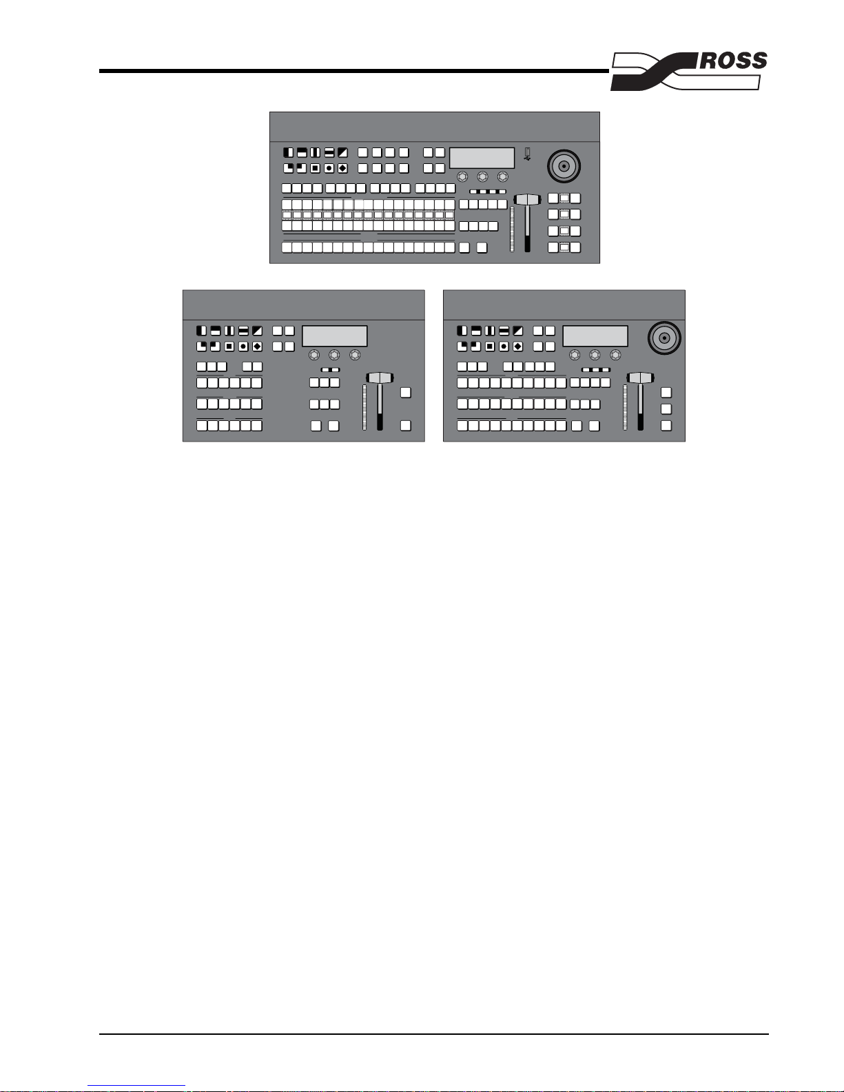
CrossOver 6 CrossOver 12
Thank you for considering the purchase of a CrossOver Multi-Definition Live Production Switcher. Each switcher in the
CrossOver family is a true multi-definition production switcher and comes fully equipped with support for a wide variety
of SD and HD video formats. CrossOver is based on the latest technology in both hardware and software, offering a
readiness for the future that is unmatched in the industry. Unlike other products on the market, no costly upgrades are
required when moving from SD to HD. All that is required is a simple software setting change. Whether your production
is in HD or SD, CrossOver will work for you - right out of the box.
Designed for Live!
CrossOver builds on the Ross Video reputation for designing switchers for live studios, trucks, and post-production. At
the center of the action, it is important that the switcher be powerful and versatile, yet maintain its ease of operation. This
frees the operator to concentrate on the programming instead of the equipment, delivering a cleaner, more professional
production.
Designed for Linear!
The CrossOver family of switchers continues to build on Ross Video’s reputation for setting the standard for multidefinition linear editing suites. The traditional layout and familiar controls of the CrossOver control panel provide the
power and ease of use you expect from a Ross switcher.
CrossOver cleanly connects to virtually any editor using the industry standard GVG100/110 protocols.
Designed for You!
With production switchers installed in over 100 countries w orld-wide, our sales, demonstration, and training people get a
lot of ongoing feedback from customers. This feedback is carefully tracked and considered in the design and feature set
development of our production switchers. The CrossOver series, our seventh generation of switchers, was designed with
the direct input of video professionals experienced in news, sports, drama, mobile, and post production. Key members of
the CrossOver design team are part of an ongoing program in which they provide switcher demonstrations, assist with
switcher installation, and train operators. As a result, the CrossOv er line contin ues to offer our legendary combination of
power and ease of use.
CrossOver Configuration Guide, v1.4 July, 2009 Page 1 of 21
Page 4

Join our Growing Customer Base!
Deciding to purchase a CrossOver switcher will put you in good company, with many thousands of Ross switchers
installed worldwide. CrossOver continues to build on a family of multi-definition switchers that have been delivering the
goods every day in live sports, stadium scoreboards, and drama productions, as well as local and network newscasts.
Experience Great Support!
Ross Video has designed and manufactured production switchers for over thirty years, with significant year over year
growth for the past 12 years. We believe that an important factor of our success is our focus on providing a superior
customer experience. We continually benchmark our w arranty and technical support to ensure that they are the best in the
industry.
We hope that you join the many thousands of satisfied video professionals around the world that are proud owners of
Ross production switchers. Please do not hesitate to contact us with any questions or comments you have related to this
Configuration Guide at Tel: +1-613-652-4886, Fax: +1-613-652-4425 or email us at solutions@rossvideo.com.
Page 2 of 21 July, 2009 CrossOver Configuration Guide, v1.4
Page 5

Product Overview
Multi-Definition — Future-proof right out of the box, CrossOver allows you to work in either SD or HD. CrossOver
supports 480i (SD 525), 576i (SD 625), 720p, 1080i.
Incredibly Powerful CrossOver 6 – The CrossOver 6 Live Production Switcher sets a new standard for small compact
switcher and chassis capability. It supports 6 Multi-Definition Serial Digital inputs , 3 Multi-Definition Serial Digital Aux
Bus outputs, 2 Multi-Definition Serial Digital Program outputs, 1 Multi-Definition Serial Digital Preview output, a single
user configurable composite output, two Keyers, 2 channels of Animation-Store with access to 1 Gigabyte of cache, 2
channels of 2D DVE, 24 user configurable GPIs, and a single Reference input with 3 adjustable Reference outputs. Add
FlexiClean™, Linux OS, and a whole lot more, and the result is nothing short of revolutionary. Amazingly, it fits into a
rack-saving 2 RU.
Incredibly Powerful CrossOver 12 – The CrossOver 12 Live Production Switcher has all the features of the
CrossOver 6, with the addition of 6 Multi-Definition Serial Digital inputs, one additional Keyer, 4 Gigabytes of
Animation-Store cache, and a 2-axis positioner.
Incredibly Powerful CrossOver 16 – The CrossOver 16 Live Production Switcher has all the features of the
CrossOver 12, with the addition of 16 source buttons with mnemonics, and a 3-axis positioner.
2D DVE — Great for sophisticated looking boxes, it allows every type of key to be zoomed, cropped, and repositioned
in 2D space, or you can use one of the useful pre-built 2D effects to perform 2D background transitions.
UltraChrome™ Advanced Chroma Keying — Our UltraChrome chroma keyer uses Ross technology to perform
detailed keying in the most demanding applications. A single UltraChrome chroma keyer is provided as a standard feature.
2 Channel Animation-Store — Two independent channels of stills are available switcher-wide, providing 1 or 4
Gigabytes of stills, logos, and animation that can be stored and recalled from a USB media drive.
Powerful MLE — The Multi-Level Effects (MLE®) of the CrossOver comes standard with fully featured keyers with
luma, and linear, plus an advanced UltraChrome chroma keyer. The MLE also has an advanced pattern generator that
includes pattern rotation, aspectization, and multiplication. An additional pattern generator is dedicated to complex wash
generation.
Upgrades from the Web — Software and even some firmware can be upgraded by downloading files from our web site.
It’s fast, easy, and it’s FREE!
Affordable — A powerful switcher at a great price!
Built to Last — Ross warranties save thousands in operational costs over competitive products. It’s no secret that Ross
products are tough. They’re built to handle years of demanding, continuous use. The CrossOver series is backed by a
comprehensive 1-year transferable warranty. The design of our fourth generation fader bars is so good that they are
guaranteed for life.
Y our purchase decision m ust be based on a careful look at your pr esent and future programming requirements. To ensure
your investment is an informed one, and that the switcher is equipped for your programming needs, Ross Video has put
together this Configuration Guide for the CrossOver switchers. In this guide, we describe the CrossOver switchers and
their many standard and optional features. As y ou go through the information, please feel free to call us. We will be happy
to address any of your questions.
CrossOver Configuration Guide, v1.4 July, 2009 Page 3 of 21
Page 6
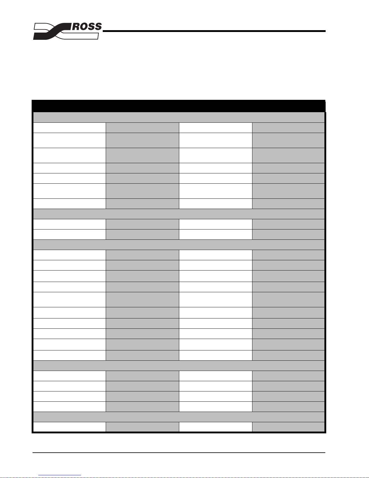
Product Comparison
Use the following table to compare the different switchers in the CrossOver product line.
CrossOver Live Production Switcher
CrossOver 6 CrossOver 12 CrossOver 16
Control Panel
Panel Source Buttons
61016
Maximum Number of MLEs
Supported
Legendary Ross Fader Handle with
Lifetime Guarantee
Source and Keyer Mnemonics
Positioner
Width × Depth
Control Panel Redundant Power
Frame
Rack Frame Height
Rack Frame Redundant Power
Video Input/Output
Multi-Definition HD/SD
Standard Definition Processing
High Definition HD/SD
SDI Inputs
SDI Outputs
Analog Outputs
1
2
111
Yes Yes Yes
No No Yes
No 2-Axis 3-Axis
16”×11”
(41cm×28cm)
Yes (optional) Yes (optional) Yes (optional)
2RU 2RU 2RU
Yes (optional) Yes (optional) Yes (optional)
Yes Yes Yes
525, 625 525, 625 525, 625
Yes Yes Yes
61212
(2×PGM, 1×PV, 3×AUX)
6
111
16”×11”
(41cm×28cm)
(2×PGM, 1×PV, 3×AUX)
6
(55cm×28cm)
(2×PGM, 1×PV,3×AUX)
21.75”×11”
6
FlexiClean™ Clean Feed System
Format Scalar and Frame Sync
Input Reference Format
Independent Reference Output
Effects Capabilities
Maximum Simultaneous Keys
Internal DVE Channels
Memory AI
UltraChrome™ Chroma Keys
Storage and Networking
USB Media Drive
3
Internal / Black Burst / Tri-Level Internal / Black Burst / Tri-Level Internal / Black Burst / Tri-Level
Page 4 of 21 July, 2009 CrossOver Configuration Guide, v1.4
Yes Yes Yes
444
333
233
222
Yes Yes Yes
111
Yes Yes Yes
Page 7

CrossOver 6 CrossOver 12 CrossOver 16
Animation-Store Still Store
Channels
Ethernet Connectivity
Linux OS
Animated Logo Players (requires
video and alpha playout)
Peripheral Interfacing
OverDrive™ Compatible
All Ross Interfaces Available
External Link Ports
Editor Protocols (GVG)
GPIs
Tallies
USB Ports
4
4
222
Yes Yes Yes
Yes Yes Yes
1 Animation-Store 1 Animation-Store 1 Animation-Store
No No No
No No No
111
100 100 100
24 24 24
688
111
1. 1080i 50/59.94, 720p 50/59.94, 480i 59.94 (4:3 and 16:9), 576i 50 (4:3 and 16:9)
2. NTSC 59.94 or PAL 50
3. 480i, 576i, 720p, 1080i (frequency is factory set)
4. OverDrive™ support, and Ross Interfaces are not available at this time
CrossOver Configuration Guide, v1.4 July, 2009 Page 5 of 21
Page 8

Standard Features
¥ Serial Digital Inputs
The CrossOver Multi-Definition, and Standard-Definition, Live Production Switchers com e standard with 6 or 12 Serial
Digital inputs. The CrossOver 6 supports 6 Multi-Definition, or Standard-Definition, Serial Digital inputs and the
CrossOver 12 supports 12 Multi-Definition, or Standard-Definition, Serial Digital inputs.
¥ Serial Digital Outputs
All CrossOver Multi-Definition, and Standard-Definition, Live Production Switchers come standard with 6 Serial Digital
outputs, consisting of 2 Program, 1 Preview, and 3 Aux outputs, and a single Analog output.
Every output is fully timed to provide consistent and adjustable output phasing.
¥ Analog Reference Input
CrossOver provides you with maximum flexibility and cost effectiveness when choosing the reference signal for your
facility. Reference can be an input from a house sync or generated internally. Although tri-level sync is recommended as
your reference source for all applications, analog black burst can be used when operating the switcher.
A single reference input and three independent reference outputs are provided for your convenience.
See the table in the Specifications section, at the rear of the Configuration Guide, for detailed reference information.
¥ 2 Channel Animation-Store
Tw o independent channels of still/animations are av ailable switcher -wide. Thousands of full screen stills and logos can be
cached and used on the CrossOver Live Production Switcher.
Animation-Store comes standard with 1 Gigabyte of cache on the CrossOver 6 and 4 Gigabytes of cache on the
CrossOver 12. The number of images cached increases considerably when smaller, non-full screen images like logos are
loaded from USB.
¥ MLE Effects System
The MLE® (Multi-Level Effect) system is standard with the CrossOver Live Production Switcher. The MLE provides a
keyer, supporting matte fill, pattern mask, box mask, self-key, linear key, and UltraChrome™ advanced chroma key.
A complex wash generator is also provided, that incorporates extensive wash patterns, matte video effects, and noise
effects while a full preview is always available to reduce on-air surprises.
¥ Powerful Pattern Generator
The CrossOver Live Production Switcher has a single pattern generator that comes equipped with 10 classic wipes. Most
wipes can be rotated, bordered, multiplied, aspectized, and repositioned.
¥ Matte/Wash Generator
The CrossOver Live Production Switcher has a single simple matte generator and complex wash generator capable of
multi-color washes. Any one of the color generators can be assigned to MATTE, or wipe pattern edges.
¥ UltraChrome Advanced Chroma Keying
The Ross UltraChrome™ uses advanced video processing technology to provide exceptional blue spill reduction and
clean edges, even with difficult source material. Glass, smoke, translucent materials, and natural shadows are handled
superbly.
Page 6 of 21 July, 2009 CrossOver Configuration Guide, v1.4
Page 9

¥ FlexiClean Clean Feed Output
FlexiClean is typically used for bilingual and live-to-tape productions. It provides a second Program output that is derived
from a different location than the standard program output. A frequent application is the recording of shows for later
airing without call-in phone numbers inserted.
The clean feed output can come from before or between the keyers. The diagram below illustrates the possible clean feed
configurations
PGM/
PST
PGM/
PST
KEY 1 KEY 2
Clean Feed Modes — CrossOver 12
KEY 1 KEY 2
Clean Feed Modes — CrossOver 6
KEY 3
PGM
FLEXICLEAN
PGM
FLEXI-
CLEAN
¥ USB Media Drive
This feature makes it possible to store and recall switcher memories, media stills, and animations to a USB media drive.
This allows operators and technical staff to back up their memories and easily transfer these settings to other CrossOver
Live Production Switchers.
¥ 100 Event Switcher Memory
CrossOver comes standard with storage for 100 complete switcher snapshots. All of these memories can be stored to a
USB media drive, providing custom tailored memories for every operator and every show.
¥ Clear and Intuitive Displays and Buttons
CrossOver always lets you know what’s going on. A unique glow color can be set for eac h CrossOver control panel. This
color is applied to all the buttons on the control panel.
Red-lit on-air sources allow you to easily identify the sources, and Keys that are on-air.
¥ Memory AI Recall Mode
CrossOver takes the guessing out of memory recalls by ensuring that a memory recall will not affect what is currently onair. Memory AI uses the content of the memory to configure the Next Transition area and Preview bus for the
background and keyers so that the next transition takes the on-air state to the same as what was stored with the memory.
¥ General Purpose Interface
CrossOver is equipped with 24 GPIs across three banks of 8 GPIs.
The GPI inputs allow the switcher to interface with peripheral equipment such as editors. Ea c h GPI input can be used to
perform simple editing and switcher functions such as fade to black or an auto transition.
CrossOver Configuration Guide, v1.4 July, 2009 Page 7 of 21
Page 10

¥ Tally Outputs
The CrossOver Live Production Switcher has 8 pre-assigned tally relays located in the rack frame. Tallies are fixed to the
first 8 inputs in a one to one relationship. Fo r the CrossOver 6, tallies are fixed to the first 6 inputs.
¥ System Manuals
CrossOver comes with a complete set of system documentation that includes an Operator’s Manual, an Engineering
Manual, and a series of Quick-Start posters.
¥ Technical Support
At Ross, we take pride in the quality of our products, but if problems occur, help is as close as the nearest telephone.
Our 24 Hour Hot Line service ensures you have access to technical expertise around the clock. After-sales service and
technical support is provided directly by Ross personnel. During business hours (eas tern standard time), technical support
personnel are available by telephone any time. After hours and on week ends, a direct emergency technical support phone
line is available. If the technical support personnel who is on call does not answer this line immediately, a voice message
can be left and the call will be returned shortly. These people are available to react to any problem and to do whatever is
necessary to ensure customer satisfaction.
¥ Repair and Warranty Policy
The CrossOver is backed by a comprehensi ve one-year w arranty on all components . CrossOv er fader handles are cov ered
with a lifetime warranty. For a more detailed description, please see our warranty document.
Page 8 of 21 July, 2009 CrossOver Configuration Guide, v1.4
Page 11

Standard Systems
CPS-1006-001
6 Input
CPS-1012-001
12 Input
CPS-1016-001
12 Input
CPSSD-1006001
6 Input
CPSSD-1012001
12 Input
CPSSD-1016001
12 Input
Whether you have a demanding production environment, or a more modest one, selecting the Liv e Production Switcher
that is right for you should not be a complicated task. Do you need 12 inputs, or would 6 be enough? Do you need the
flexibility of a full Multi-Definition Live Production Switcher, or would a Standard-Definition Live Production Switcher
be enough? Do you want to mount your switcher in a desk, or on top of it? Those are all the questions you need to ask
yourself when looking at a CrossOver Live Production Switcher. The rest is already included.
¥ CrossOver Multi-Definition Live Production Switcher
Do you have a production environment where space is at premium? Compact, easy to use, and
powerful are all terms use to describe the CrossOver Multi-Definition Live Production Switcher.
The CrossOver 6 Multi-Definition Live Production Switcher (CPS-1006-001) has 2 Keyers, 6
Crosspoint source buttons, 6 Multi-Definition dedicated outputs, a single SD only analog output, and 6
Multi-Definition Serial Digital inputs.
The CrossOver 12 Multi-Definition Live Production Switcher (CPS-1012-001) has all the features
of the CrossOver 6 Multi-Definition Live Production Switcher, ex cept that it has 12 Multi-Definition
Serial Digital inputs, 3 Keyers , 10 Crosspoint source buttons , a 2-axis positioner , and 3 Au x Bus Assign
buttons.
The CrossOver 16 Multi-Definition Live Production Switcher (CPS-1016-001) has all the features
of the CrossOver 6 Multi-Definition Live Production Switcher, ex cept that it has 12 Multi-Definition
Serial Digital inputs, 3 Keyers, 16 Crosspoint source buttons with keyer mnemonics, a 3-axis
positioner, and 3 Aux Bus Assign buttons.
¥ CrossOver Standard-Definition Live Production Switcher
Do you require the compact size and easy of use of the CrossOver Live Production Switcher but don’t
need High-Definition? The CrossOver Standard-Definition Live Production Switcher provides the
same powerful features as the CrossOver Multi-Definition Live Production Switcher, but in StandardDefinition only.
The CrossOver 6 Standard-Definition Live Production Switcher (CPSSD-1006-001) has 2 Keyers,
6 Crosspoint source buttons, 6 Standard-Definition dedicated outputs, a single SD only analog output,
and 6 Multi-Definition Serial Digital inputs.
The CrossOver 12 Standard-Definition Live Production Switcher (CPSSD-1012-001) has all the
features of the CrossOver 6 Standard-Definition Live Production Switcher, except that it has 12
Standard-Definition Serial Digital inputs, 3 Keyers, 10 Crosspoint source buttons, a 2-axis positioner,
and 3 Aux Bus Assign buttons.
The CrossOver 16 Standard-Definition Live Production Switcher (CPSSD-1016-001) has all the
features of the CrossOver 6 Standard-Definition Live Production Switcher, except that it has 12
Standard-Definition Serial Digital inputs, 3 Keyers, 16 Crosspoint source buttons with keyer
mnemonics, a 3-axis positioner, and 3 Aux Bus Assign buttons.
CrossOver Configuration Guide, v1.4 July, 2009 Page 9 of 21
Page 12

¥ CrossOver 1 MLE Live Production Switcher Frame ONLY
CPS-1006-001FRAME
6 HD Inputs
CPS-1012-001FRAME
12 HD Inputs
CPSSD-1006001-FRAME
6 SD Inputs
CPSSD-1012001-FRAME
12 SD Inputs
CPS-1006-001PANEL
6 source buttons
CPS-1012-001PANEL
12 source buttons
CPS-1016-001PANEL
16 source buttons
Do you need the keying or chroma key power of multiple CrossOver 6 or 12 frames, but don’ t need a
control panel connected to each one? With a single control panel and multiple frames, you can have
multiple independent chroma keyers without the clutter or expense of multiple unused control panels.
If you need to tweak the settings on one of the frames , simply connect y our control panel to the frame
and make the changes. For fast switching between frames , connect all y our frames and control panel to
a serial switch, and simply dial in the frame you want to control.
Offset your upgrade costs by purchasing your control panel and frame at different times. Any of the
CrossOver frames can be purchased separate from the control panels.
Note: Only one control panel can be connected to a frame at a time.
¥ CrossOver 1 MLE Live Production Switcher Panel ONLY
Do you have a CrossOver 6 or 12 frame and w ant to upgrade your panel? Offset your upgrade costs by
purchasing your control panel and frame at different times.
Maybe you need an additional control panel to meet your production needs? Any of the CrossOv e r
control panels can be purchased separate from the frame.
Note: Only one control panel can be connected to a frame at a time.
Page 10 of 21 July, 2009 CrossOver Configuration Guide, v1.4
Page 13

System Options
CPSSD-1006HDUPG
6 Input
CPSSD-1012HDUPG
12 Input
CPSSD-1016HDUPG
12 Input
CPS-REDPSUEXT
CPS-INDESK
CPS-INDESK16
CPSANALOGIO1
Options are typically ordered when the switcher is purchased. How ev er, you can order options if y our needs c hange in the
future. All of our options can be easily installed in the field. You can take comfort in knowing that you can purchase
options in the future and that installation at your site will be a smooth process.
¥ CrossOver Standard-Definition Live Production Switcher HD Upgrade
The CrossOver Standard-Definition Live Production Switcher can be upgraded to full MultiDefinition with this option. Start out with the CrossOver Standard-Definition Live Production
Switcher and upgrade to full Multi-Definition when your needs change.
¥ Redundant Power (Frame and Panel)
The redundant power supply option provides protection against AC power failure. It allow two
external power supplies to receive power from independent power sources. Complete failure of one
source, or power supply, will not affect the operation of the switcher in the slightest. If the main AC
power fails, the switcher instantly draws power from the remaining source. The transition from one
power source to the other is totally transparent and has no effect on the output of the switcher; a
critical feature should one power source fail during an on-air broadcast.
¥ In-Desk or In-Rack Secure Mounting Kit (CrossOver 6 or 12)
This option provides two mounting options for the CrossOver 6 or 12 control panel. A versatile
mounting bracket is attached to the bottom of the CrossOver control panel and provides a flange on
either side of the control panel. This flange allows the CrossOver control panel to be mounted into a
desk and screwed down, or mounted vertically into a rack frame.
The CrossOver control panel required at least 7RUs to mount it into a rack frame. This includes 1RU
for cable bend relief.
¥ In-Desk Secure Mounting Kit (CrossOver 16)
This option provides an in-desk mounting option for the CrossOver 16 control panel. A mounting
bracket is attached to the bottom of the CrossOver 16 control panel and provides a flange on either
side of the control panel that can be screwed down into the desk.
¥ Analog I/O Pack for SD Signals
Note: This option must be purchased at the same time as your CrossOver Live Production Switcher.
CrossOver Configuration Guide, v1.4 July, 2009 Page 11 of 21
This option provides input and output support for analog video formats, such as RGB/YPbPr or YC/
CVBS. A single (1) Ross GearLite DAC-9013 SDI to Analog Composite/Component Video Converter
is provided for analog Program Out, and four (4) Ross GearLite ADC-9033 Analog Composite/
Component/YC to ADI Video Converter for analog Inputs.
Page 14

¥ Onsite Operational Training, 1 Day
CPS-TRAIN1DAY
CPS-999
CPS-999-16
Although CrossOver was designed to be as easy as possible to install and operate, training is highly
recommended to ensure that the process of taking your Ross Video switcher to air is a smooth one.
Training courses can be conducted at the customer's site or at Ross facilities. Expenses are included in
North America. A minimum of four weeks advance notice is required for training to ensure that we can
efficiently schedule the best possible training staff for your requirements. Onsite training is provided
on the customer's switcher.
Customers are not charged for the travel time of the trainer .
¥ Extended Warranty (CrossOver 6 or 12)
This extends the standard one-year warranty on your CrossOver 6 or 12 Live Production Switcher by
one year. Additional years can be purchased if required.
¥ Extended Warranty (CrossOver 16)
This extends the standard one-year warranty on your Cr ossOver 16 Live Production Switcher by one
year. Additional years can be purchased if required.
Page 12 of 21 July, 2009 CrossOver Configuration Guide, v1.4
Page 15

Specifications
Physical Characteristics – CrossOver Control Panel
ALL
C
ORE RE
T
S
MENU NEXT
LOAD
AUX
DSK 2
DSK 1
1
SEL
SEL
E
DV
KEY/AUX
INPUT 4/
INPUT 3/
INPUT 2/
12
A
MEDI
INPUT 11
INPUT 10
PROGRAM
AUX
AUX
PREV CLN
PGM
PUSH PUSH PUSH
AUX
AUX
3
2
INPUT 8/
SHIFTINPUT 6INPUT 5
INPUT 7/
MEDIA 2
MEDIA 1
PRESET
BKGD KEY
DISS WIPE DVE
CUT
DSK 2DSK 1
AUTO
TRANS
Width
Height
Depth
CrossOver Control Panel Size
OPTIONS SYS 1 SYS 2 REF CONFIG
USER PERS SAVE
RESET
CHR
AUTO
KEY
SEL
INPUT 1/
BLACK/
INPUT 9
MATTE
CrossOver 6 CrossOver 12 CrossOver 16
KEY
TRANS
DSK 1
TRANS
DSK 2
TRANS
Width
Depth
Height
Height Above Desktop
Panel Source Buttons
15.85”
(40.3 cm)
10.64”
(27.0 cm)
3”
(7.6 cm)
4.81”
(12.2 cm)
61016
Desk Cutout Size
Width
Depth
18”
(45.7 cm)
11”
(27.9 cm)
Connector Types
External Link Port
AC Power
RJ-45 RJ-45 RJ-45
External DC Power Brick External DC Power Brick External DC Power Brick
Physical Characteristics – CrossOver Frame
CrossOver 6 CrossOver 12
15.85”
(40.3 cm)
10.64”
(27.0 cm)
3”
(7.6 cm)
4.81”
(12.2 cm)
18”
(45.7 cm)
11”
(27.9 cm)
21.75”
(55.3 cm)
10.75”
(27.3 cm)
4”
(10.6 cm)
4.81”
(12.2 cm)
23.62”
(60.0 cm)
11.5”
(29.2 cm)
CrossOver Frame
Width
Height (2 RU)
Depth
Connector Types
Video I/O
Editor Port
CrossOver Configuration Guide, v1.4 July, 2009 Page 13 of 21
19”
(48.3 cm)
3.5”
(8.89 cm)
15.63”
(39.7 cm)
19”
(48.3 cm)
3.5”
(8.89 cm)
15.63”
(39.7 cm)
BNC-Type BNC-Type
D-Type, 9-pin, Female D-Type, 9-pin, Female
Page 16

CrossOver 6 CrossOver 12
USB Port A-Type A-Type
Tally Ports
GPI I/O
Ethernet Port
Reference Out
AC Power
Power Rating – Tallies
Input Voltage 24VAC (rms) / 40VDC
Maximum Current
Impedance
Power Consumption
Power Consumption – Frame
Consumption
Input Voltage
D-Type, 9-pin, Female D-Type, 9-pin, Female
D-Type, 25-pin ,Female D-Type, 25-pin ,Female
RJ-45 RJ-45
BNC-Type BNC-Type
3-pin IEC 3-pin IEC
All CrossOver Switchers
170mA
< 15 ohms
CrossOver 6 & 12 CrossOver 16
81W 6.75A 12V 81W 6.75A 12V
100 - 120V~
220 - 240V~
47-63Hz
1.6A
100 - 120V~
220 - 240V~
47-63Hz
1.6A
Power Consumption – Panel
Consumption
Input Voltage
Environmental Characteristics
Ambient Temperature Range 0 - 35°C (32 - 95°F)
Frame Cooling
Control Panel Cooling
Video Characteristics
Supported Video Formats
480i/59.94 (SD 525)
576i/50 (SD 625)
24W 2A 12V 26W 2A 12V
100 - 120V~
220 - 240V~
47-63Hz
1.5A
100 - 120V~
220 - 240V~
47-63Hz
1.5A
All CrossOver Switchers
Active, Front-to-Back airflow
Power Supply
All CrossOver Switchers
SMPTE 125M, SMPTE 259M
ITU-R BT.601-5, SMPTE 259M
Page 14 of 21 July, 2009 CrossOver Configuration Guide, v1.4
Page 17

All CrossOver Switchers
720p/59.94 SMPTE 296M, SMPTE 292M
720p/50
1080i/50, 1080i/59.94
• 10 bit 4:2:2 component digital video and key processing
• 4:3 and anamorphic 16:9 switchable aspect ratio where applicable
• Contract Ross Video for additional format compatibility
Video Inputs
CrossOver 6 — Number of Inputs
CrossOver 12 — Number of Inputs
CrossOver 16 — Number of Inputs
Equalization (using Belden 1694 cable)
Impedance
Return Loss
• All inputs are SMPTE-259M/292M serial digital non-looping.
• Inputs can be used for either key or video.
• The reference input is selectable, analog black for St andard De finition op eration, and the
recommended tri-level sync for High Definition operation.
Video Outputs
Number of Outputs
Return Loss
Rise and Fall Time
Signal Level
DC Offset
SMPTE 296M, SMPTE 292M
SMPTE 274M, SMPTE 292M
6
12
12
> 180m @ 1.5Gb/s
> 300m @ 270Mb/s
75 ohm, terminating
> 20dB @ 1.5GHz
7 (6 SDI and 1 SD analog)
> 16dB @ 1.5GHz
800ps +/- 10% (SD)
240ps +/- 10% (HD)
800mV +/- 10%
0 volts
Overshoot
• All video outputs are 10-bit SMPTE-259M-C (SD Mode) or 10-bit SMPTE-292M serial
digital (HD Mode).
• EDH is inserted into all outputs and can be disabled. Aux Bus outputs do not have EDH
insertion but do pass previously inserted EDH. (SD Video Mode).
• Line CRCs are inserted into all outputs and can be disabled. Aux Bus outputs do not
have line CRCs inserted but do pass previously inserted line CRCs. (HD Video Mode).
Jitter
Video Mode
HD – Tri-Level Sync
HD – Composite Reference
SD – Tri-Level Sync
SD – Composite Reference
System Timing
• All video inputs zero time relative to reference input, auto timing will correct for inputs out
of time by up to +/- 0.25 line.
• System delay approximately 500 pixels.
< 8%
Alignment (> 100KHz) < 0.2UI
Timing (<10Hz) < 1.0UI
Performance not guaranteed with
composite reference
Alignment (> 1KHz) < 0.2UI
Timing (<10Hz) < 0.2UI
Alignment (> 1KHz) < 0.2UI
Timing (<10Hz) < 0.5UI
CrossOver Configuration Guide, v1.4 July, 2009 Page 15 of 21
Page 18

System Reference
All CrossOver Switchers
Reference Format
480i/59.94
576i/50
720p/50
720p/59.94
1080i/50
1080i/59.94
Video Format
480i/59.94, 480i 16:9/59.94, 1080i/59.94,
720p/59.94
576i/50, 576i 16:9/50, 1080i/50, 720p/50
720p/50
720p/59.94
576i/50, 576i 16:9/50, 1080i/50, 720p/50
480i/59.94, 480i 16:9/59.94, 720p/59.94,
1080i/59.94
Note: Specifications are subject to change without notice.
Note: CrossOver switchers meet applicable world standards for safety, emissions, and immunity.
IN 1
IN 2 IN 3 IN 4 IN 5 IN 6
ANLG
AUX 1 AUX 2 AUX 3 PV PGM PGM REF IN
OUT
REF
OUT1
PS 1 PS 2
TALLY
EDITOR
GP I
PANEL
REF
OUT2
REF
OUT3
TALLY
PS 1 PS 2
I
O
PS1
EDITOR
PS2 FRAME
CrossOver 6 Frame — Rear View
IN 1
IN 2 IN 3 IN 4 IN 5 IN 6 IN 7 IN 8 IN 9 IN 10 IN 11 IN 12
GP I
PANEL
AUX 1 AUX 2 AUX 3 PV PGM PGM REF IN
CrossOver 12 Frame — Rear View
EXT
LINK
CrossOver 6 Control Panel — Rear View
ANLG
OUT
REF
OUT1
REF
OUT2
REF
OUT3
Page 16 of 21 July, 2009 CrossOver Configuration Guide, v1.4
Page 19

I
O
PS1
PS2 FRAME
I
O
PS1
PS2 FRAME
EXT
LINK
CrossOver 12 Control Panel — Rear View
EXT
LINK
CrossOver 16 Control Panel — Rear View
CrossOver Configuration Guide, v1.4 July, 2009 Page 17 of 21
Page 20

Option Summary
CrossOver Live Production Switcher
CrossOver 6 CrossOver 12 CrossOver 12
Live Production Switcher
CrossOver Multi-Definition Live Production
Switcher
CPS-1006-001 CPS-1012-001 CPS-1016-001
CrossOver Standard-Definit i on Live
Production Switcher
CrossOver 1 MLE Live Production
Switcher Frame ONLY (HD Inputs)
CrossOver 1 MLE Live Production
Switcher Frame ONLY (SD Inputs)
CrossOver 1 MLE Live Production
Switcher Panel ONLY
Additional Options
Redundant Power, Frame and Panel
In-Desk or In-Rack Secure Mounting Kit
CrossOver Standard-Definit i on Live
Production Switcher HD Upgrade
Onsite Operational Training, 1 Day
Extended Warranty, 1 Year
Analog I/O Pack for SD Signals
CPSSD-1006-001 CPSSD-1012-001 CPSSD-1016-001
CPS-1006-001-
FRAME
CPSSD-1006-001-
FRAME
CPS-1006-001-
PANEL
CPS-REDPSU-EXT CPS-REDPSU-EXT CPS-REDPSU-EXT
CPS-INDESK CPS-INDESK CPS-INDESK16
CPSSD-1006-
HDUPG
CPS-TRAIN-1DAY CPS-TRAIN-1DAY CPS-TRAIN-1DAY
CPS-999 CPS-999 CPS-999-16
CPS-ANALOGIO1 CPS-ANALOGIO1 CPS-ANALOGIO1
CPS-1012-001-
FRAME
CPSSD-1012-001-
FRAME
CPS-1012-001-
PANEL
CPSSD-1012-
HDUPG
CPS-1012-001-
FRAME
CPSSD-1012-001-
FRAME
CPS-1016-001-
PANEL
CPSSD-1016-
HDUPG
Page 18 of 21 July, 2009 CrossOver Configuration Guide, v1.4
Page 21

Notes:
CrossOver Configuration Guide, v1.4 July, 2009 Page 19 of 21
Page 22

Notes:
Page 20 of 21 July, 2009 CrossOver Configuration Guide, v1.4
Page 23

Trademarks
• Ross, Ross Video, MLE, OverDrive, UltraChrome, FlexiClean, and CrossOver, RossGear, openGear,
DashBoard, and GearLite, are trademarks of Ross Video Limited
CrossOver Configuration Guide, v1.4 July, 2009 Page 21 of 21
Page 24

Request for Quotation
PAGE ____ of ____
Customer Information
Company __________________________________________
Contact Name __________________________________________
E-mail __________________________________________
Telephone (s) __________________________________________
Address __________________________________________
__________________________________________
__________________________________________
__________________________________________
Item # Option Number Option Name Quantity
Ross Video Incorporated, P.O. Box 880, Ogdensburg, New York, USA 13669 0880
Ross Video Limited, P.O. Box 220, 8 John St., Iroquois, ON., Canada K0E 1K0
Tel. +1 (613) 652-4886
Fax. +1 (613) 652-4425
 Loading...