

Page 1
Installation and Cabling
4840DR-200-02
© 2016 Ross Video Limited. Ross®, CrossOver®, and any related marks are trademarks or registered trademarks of Ross Video Limited. All other trademarks are the property of their respective companies. PATENTS ISSUED and PENDING. All rights reserved. No part of this publication may
be reproduced, stored in a retrieval system, or transmitted in any form or by any means, mechanical, photocopying, recording or otherwise, without the prior written permission of Ross Video. While every precaution has been taken in the preparation of this document, Ross Video assumes no
responsibility for errors or omissions. Neither is any liability assumed for damages resulting from the use of the information contained herein.
Caution: Before you set up and operate your switcher, see the
“Important Safety Instructions” in your Setup manual.
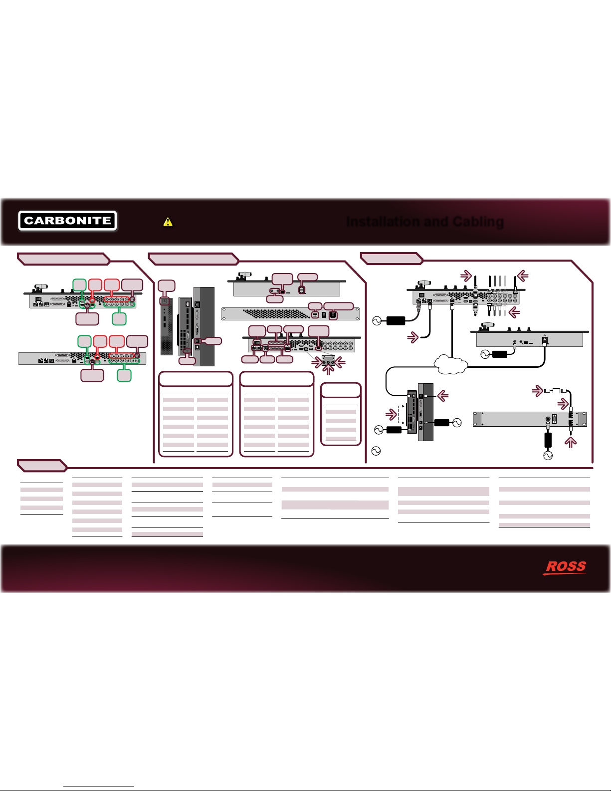
Power and Cabling
Video Inputs/Outputs/Reference
Pin
1
2
3
4
5
6
7
8
RS-422
Tx+
TxRx+
n/c
n/c
RxGround
Ground
Serial
(female RJ-45)
GPI I/O
(female DB25)
1
2
3
4
5
6
7
8
9
10
11
12
13
Pin Pin
GPI I/O 1
GPI I/O 2
GPI I/O 3
GPI I/O 4
GPI I/O 5
GPI I/O 6
GPI I/O 7
GPI I/O 8
GPI I/O 9
GPI I/O 10
GPI I/O 11
GPI I/O 12
GPI I/O 13
Signal Signal
14
15
16
17
18
19
20
21
22
23
24
25
GPI I/O 14
GPI I/O 15
GPI I/O 16
GPI I/O 17
GPI I/O 18
GPI I/O 19
GPI I/O 20
GPI I/O 21
GPI I/O 22
GPI I/O 23
GPI I/O 24
Ground
Tally
(female DB25)
1
2
3
4
5
6
7
8
9
10
11
12
13
Pin Pin
Tally 1
Tally 2
Tally 3
Tally 4
Tally 5
Tally 6
Tally 7
Tally 8
Tally 9
Tally 10
Tally 11
Tally 12
Tally 13
Tally Tally
14
15
16
17
18
19
20
21
22
23
24
25
Tally 14
Tally 15
Tally 16
Common
Common
Common
Common
Common
Common
Common
Common
Common
Specifications
Video Output Specifications
Return Loss
Rise and Fall Time
Signal Level
DC Offset
Overshoot
SDI HD Mode
HDMI
< -23dB at 1.5GHz
< -18dB at 3GHz
800ps +/- 10% (SD)
240ps +/- 10% (HD)
800mV +/- 10%
0 Volts
< 10%
10-bit SMPTE-292M serial digital
HDMI 1.4
High Speed HDMI Cable
AES Output Specifications
Audio Depth
Channels
File Format
Impedance
Min/Max Output Voltage
Swing
Rise and Fall Times
Sample Rate
Synchronization
24-bit in HD
20-bit in SD
1 Stereo Pair
Multi-Channel Waveform
Audio File
110 Ohms, differential
1.5/6V peak-to-peak
20ns (typical)
48kHz
Locked to Video
SDI Input Formats
480i 59.94Hz
576i 50Hz
720p 59.94Hz
720p 50Hz
1080i 59.94Hz
1080i 50Hz
1080pSF 23.98Hz
1080pSF 25Hz
1080pSF 29.97Hz
1080p 29.97Hz
1080p 25Hz
1080p 50Hz Level A
1080p 59.94Hz Level A
Default Values
Frame IP
FTP User name
FTP Password
192.168.0.123
user
password
Tally Rating
Input Voltage:
Maximum Current:
Impedance:
24VAC (rms) / 40VDC
120mA
< 15 ohms
Temperature
Operating:
Storage:
0 - 40°C (32 - 104°F)
-20 - 85°C (-4 - 185°F)
Power Consumption
Solo
CBF-109
CB9
57W 4.75A 12V
45W 3.75A 12V
24W 2.00A 12V
Input Voltages
All
100 - 120V~
220 - 240V~
47-63Hz
Ports, Pinouts, and Diagnostics
Notes:
• The MultiViewer is assigned to output BNC 5 or HDMI
Out.
• Only Media-Store audio can be output on the AES
audio output. Audio is not embedded in the MultiViewer
output.
• HDMI output formats are the same as the switcher is
operating in. No format conversion is applied to the
output.
Note: Carbonite Black Solo and CBF-109 use the PSU-12V9A-6PIN power supply.
Power
Switch
Power
Power
DashBoard
Display
(rear)
(front)
HDMI Input Formats
VGA
SVGA
XGA
SXGA
720p
1080i
1080p
640×480 (4:3)
800×600 (4:3)
1024×769 (4:3)
1280×1024 (5:4)
1280×720 (16:9)
1920×1080 (16:9)
1920×1080 (16:9)
Video Input Specifications
Equalization
(using Belden 1694 cable)
Impedance
Video Inputs, SDI
Video Inputs, HDMI
Reference Inputs
(non-terminating, looping)
>100m @ 1.5 Gb/s
>300m @ 270 Mb/s (5°-40°C)
75 ohm, terminating
SMPTE 259M/292M serial digital
(non-looping)
HDMI 1.4
High Speed HDMI Cable (Max 10m)
Standard Definition — analog black
High Definition — tri-level sync
ON
OFF
POWER
PS1 PS2
SERIAL
TALLY
GPIO
OUT1 OUT2 OUT3 OUT4 OUT5
REF IN
IN1 IN2 IN3 IN4 IN5 IN6
UPGD SD
HDMI IN2
HDMI IN1
HDMI OUT1
HDMI IN3
AES
1 2 3 4
Input
BNCs
HDMI
IN
Output
BNCs
HDMI
Out
AES Audio
Output
Reference
In
Solo
PS1 PS2
SERIAL
TALLY
GPIO
OUT1 OUT2 OUT3 OUT4 OUT5
REF IN
IN1 IN2 IN3 IN4 IN5 IN6
SD
HDMI IN2
HDMI IN1
HDMI OUT1
HDMI IN3
AES
1 2 3 4
CBF-109
Input
BNCs
HDMI
IN
Output
BNCs
HDMI
Out
AES Audio
Output
Reference
In
UPGRADE POWER
ON
OFF
CBF-109
USB
Power Switch
ON
OFF
POWER
PS1 PS2
SERIAL
TALLY
GPIO
OUT1 OUT2 OUT3 OUT4 OUT5
REF IN
IN1 IN2 IN3 IN4 IN5 IN6
UPGD SD
HDMI IN2
HDMI IN1
HDMI OUT1
HDMI IN3
AES
1 2 3 4
Connect video
inputs as needed
For MultiPanel and/or
Connecting to CB9
Connect external
reference or use
internal reference
Connect Program, Preview,
and aux outputs as needed
To Remote Aux
Panel or external
serial device.
1
2
PS1
PS2
SD
1 2 3 4
Black Cable Adapter between
Serial port on switcher and
RJ12 Telco Cable
10m RJ12
Telco Cable
To more
Remote
Aux Panels
Remote Aux Panel
Mains
Power
Note: It is recommended that you always connect
the AC Power Adapter to the device before connecting
to Mains Power.
DashBoard Display
To OSD
Remote
VESA
100
Ethernet
ON
OFF
POWER
PS1 PS2
SERIAL
TALLY
GPIO
OUT1 OUT2 OUT3 OUT4 OUT5
REF IN
IN1 IN2 IN3 IN4 IN5 IN6
UPGD SD
HDMI IN2
HDMI IN1
HDMI OUT1
HDMI IN3
AES
1 2 3 4
GPI I/OSerial
NetworkTally
Power
Switch
AES- AES+
GND
DIP
Switches
Power
Solo
1
2
PS1
PS2
SD
1 2 3 4
CB9
Network
DIP
Switches
Power
 Loading...