

Page 1

1
OPERATING INSTRUCTIONS COOKER
" 4040 DB AUS "
Page 2

2
All these characteristics are given for information with a constant concern
for improving production quality,
ROSIERES may make modifications to the appliance to incorporate technical improvements.
In conformity with directives CEE 89/336, CEE 73/23 and CEE 90/396.
1 - Hot plate burner 4,5 kW - Cast-iron plate or Steak griddle
2 - Fast burner 2,5 kW
3 - Medium burner 1,45 kW
4 - Ultra-fast burner 3,5 kW
5 - Fast burner 2,5 kW
6 - Push-button ignitor for gas burner and hot plate
7 - Push-button for oven interior lights
8 - Natural convection oven with slide-out, catalytic enamel insert
9 - Left hand oven temperature control knob
10 - Multifunction oven, normal enamel
11 - Selector knob for fan cooking in
12 - Left hand oven temperature control knob
13 - Left hand oven orange temperature control light
14 - Red oven on mains indicator light
15 - Right hand oven orange temperature control light
" 4 0 4 0 D B A U S "
Page 3

3
Dimensions of the appliance
Width : 119,5 cm
Depth : 60 cm
Height with back panel : 95 cm
Below back panel : 84 cm
--------------------------------------------------------------------------------------------------------------------THE HOB (burners)
Left hand side Right hand side
1 hot plate 4,5 kW 1 medium 1,65 kW
2 fast 2,65 kW
1 ultra-fast 3,8 kW
--------------------------------------------------------------------------------------------------------------------THE OVENS
multifunction natural convection
Usable oven dimensions :
Width 42,5 41,5
Depth 38 35,5
Height 29,5 28,5
Usable oven 47 l 41 l
Power rating
Fan convection : 2,42 kW
Natural convection : 2,39 kW 2,39 kW
Grill : 2,11 kW 2,11 kW
Power consumption
Natural convection
to reach 200°C 0,4 kWh 0,4 kWh
to hold at 200°C for 1 h 0,5 kWh 0,5 kWh
Total 0,9 kWh 0,9 kWh
Fan convection
to reach 175°C 0,4 kWh
to hold at 175°C for 1 h 0,5 kWh
Total 0,9 kWh
--------------------------------------------------------------------------------------------------------------------Total electrical power (230 V) : 4,84 kW
Total gas power : 14,95 KW
--------------------------------------------------------------------------------------------------------------------Gas according to regulation : Natural - Propane
SQn Natural G20 10 mbar : 1424 l/h
SQn Propane G31 27,5 mbar : 1068 g/h
---------------------------------------------------------------------------------------------------------------------
TECHNICAL DATA
Page 4
4
The burners are fitted with a thermocouple safety device which automatically shuts off the gas
if the flame is extinguished.
IGNITION :
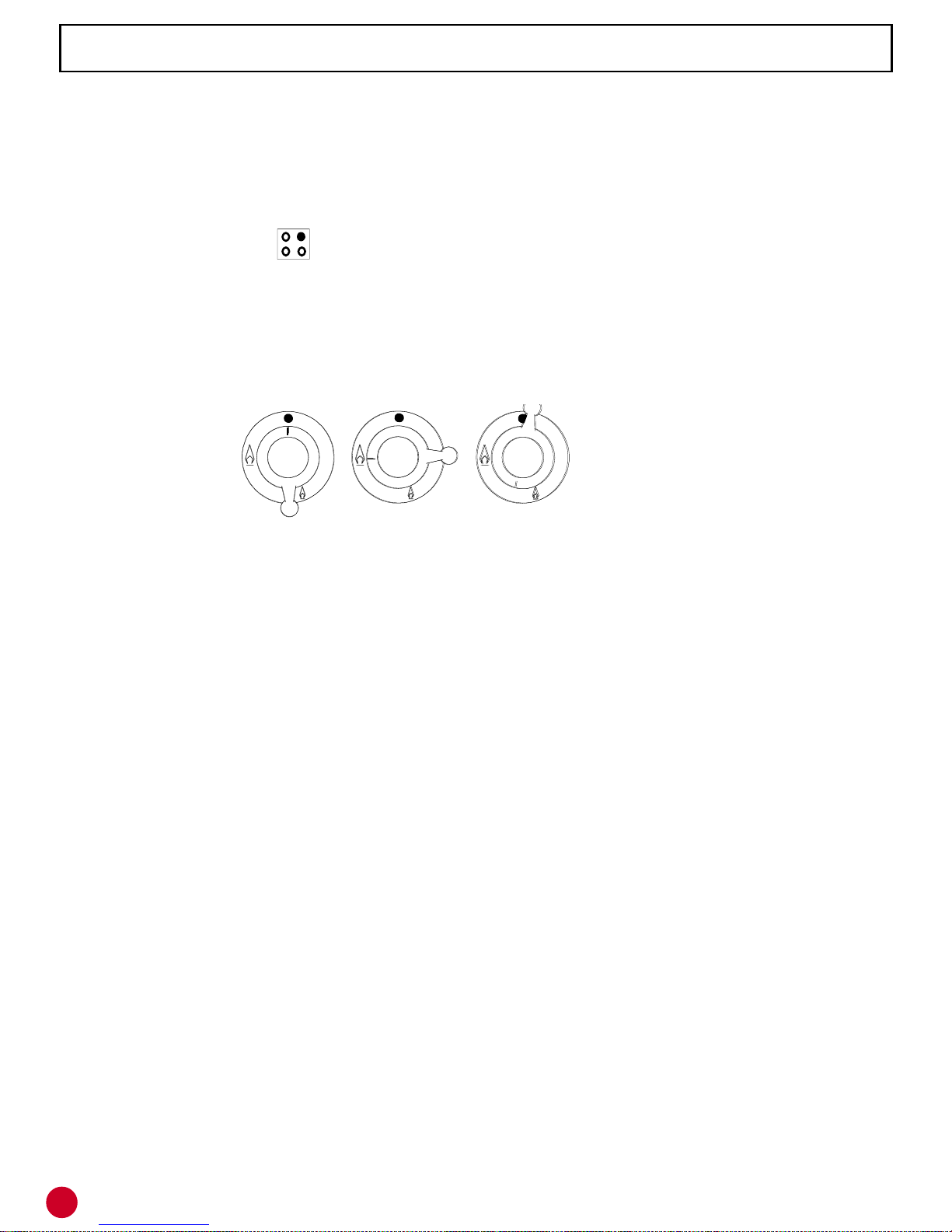
. a symbol next to each control knob indicates which burner is being used.
Eg.: for rear RH burner .
. push the knob down and turn full on, simultaneously,
. press the ignition button "6" for the burners, and,
. continue to hold the knob down for 15-20 seconds to allow the safety system to operate.
Each burner is supplied with a tap which incorporates a safety catch and a slow burning
position, see below. Between the high and low positions the control knob can be adjusted to
any required flame height.
The hob is fitted with burners of varying sizes and heat ratings. Full use should be made of this
feature.Use the small burner for simmering and for sauces.
Avoid boiling food too rapidly. Food is not cooked more quickly in this way but excessive boiling
will impair the flavour.
To ensure fuel economy do not have flames up the sides of the pan.
THE HOT PLATE BURNER
The hot plate enables you to use large cooking vessels or to cook several dishes at the same
time. It is more powerful than a normal gas burner and allows you to :
- simmer for long periods without having to watch the food.
- to keep food hot without burning it.
- to prepare special sauces without using a "bain-marie".
- Steak griddle.
- Left open for Wok cooking.
Depending on the dish that you are preparing, you can either adjust the burner or change the
position of the cooking vessel on the hot plate, the centre being the hottest, and cooler areas
nearer the outer edges.
Example : TO COOK A STEW. Place cooking oil in a saucepan and place in the middle of the
hot plate, set on a high position. Add the meat and seal in the hot oil. Add the wine, vegetables,
seasoning and herbs, and finish cooking on a low setting with the saucepan placed to one side
of the hot-plate.
IMPORTANT RECOMMENDATION :
When the burners are not being used the mains gas supply valve should be closed.
OFF FULL LOW
OPEN HEAT
THE GAS BURNERS
Page 5
5
WARNING : The oven doors are hot when the oven is on,
keep young children away.
The natural convection or conventional cooking is available on the two ovens.
With this method of cooking the heat naturally rises, therefore the higher shelf positions are
hotter than the lower ones. So it is possible, for instance to cook a casserole or braise
vegetables on a low shelf, while cooking pastry dishes or baking potatoes on a higher shelf.
This method of cooking is often preferred by the cook, who likes to braise casseroles in thick
earthenware dishes, or bake puddings slowly and gently. The results of this method may be
preferred as crusts on baked dishes are often browner and crisper.
The best results using a conventional oven are achieved when cooking on one shelf only. If
you are using more than one shelf, tins will probably need changing halfway through the
cooking time. Unless a recipe indicates otherwise, use a middle shelf position in the oven when
cooking on one level only. Set a temperature on the knob for the meat.
USE :
• Turn the oven thermostat control knob "9" or "12" to the required position.
The red light will always be on while the oven is in use.
The orange light indicates the function of the thermostat. It will therefore go on and off
regularly throughout the cooking, indicating the set temperature has been reached.
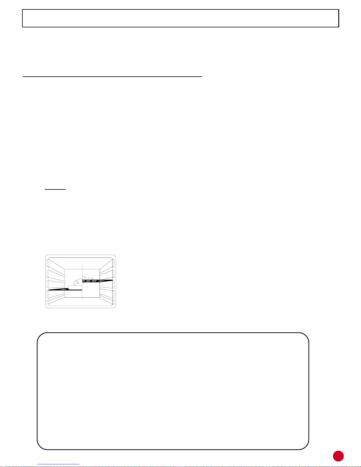
Place the food
to be cooked in the
centre of the oven.
Oven temperature Guide
(Taken to the nearest round fig)
C° F° C° F°
100 200 200 400
110 225 220 425
150 300 240 475
180 350
Pre-heating time
60°-90°C takes between 5-10 mins
120°-180°C takes between 10-15 mins
220°-280°C takes between 15-20 mins
THE NATURAL CONVECTION OVEN
Page 6

6
THE THERMOST AT
sdooFytitnauQ
erutarepmeT
gnikoocfo
nossiuC
gnikooC
emit
nevO
noitisop
desiarbrodetsaor,hsifelohWdesiarbrodetsa
or,hsifelohW
desiarbrodetsaor,hsifelohW
desiarbrodetsaor,hsifelohWdesiarbrodetsaor,hsifelohW
hsiFgk1022/002'
021
selbategevtaeMselbategevtaeM
selbategevtaeM
selbategevtaeMselbategevtaeM
kcuDgk5,1022/00203h11
egabbacdesiarB.
srep6022/002.xorppah11
skeeL.srep6022/002.xorppah11
bmalfogeL022/002olik/p'511
yekrutesooGgk7081/061h3-03h21
seiP022/002o
lik1rofruoh11
nekcihctsaoR002gk1/1022/002ruoh1-'541
tratyruovaS
6-72Ø
.srep
022/002'05/041
feebtsaoR042/032olik/pnim
511
stresseDstresseD
stresseD
stresseDstresseD
ekaC005gk1002/081'06/051
ekactiurF
6-72Ø
.srep
022/002'54/041
lemaracemè
rC
laudividni
nikemar
09/08
'54
reliobelbuodni
1
yrtsapuohC002'043
tiucsibylbmurC005gk1022/002ruoh1/'541
ekacdehsinra
G
6-72Ø
.srep
022/002'54/041
Page 7

7
WARNING : The oven doors are hot when the oven is on,
keep young children away.
Left oven only : Fan (forced convection) oven cooking.
For this method of cooking the oven is used with the fan button depressed. The fan will circulate
the warm air produced from the upper and lower elements to produce a constant heat inside
the oven. Because the temperature is uniform inside the oven cavity there will be no problems
when the oven is filled to maximum capacity with various dishes, allowing you to save time and
energy. Batch baking is recommended.
USE :
• Turn the left hand oven thermostat control knob "12" to a temperature between 60°
and 240°C.
• Depress the fan button "11".
The red light will always be on while the oven is in use.
The orange light indicates the function of the thermostat. It will therefore go on and off
regularly throughout the cooking, indicating the set temperature has been reached.
When cooking with a fan oven it is generally recommended that you use lower temperatures
and reduced times. This is because the circulating air in a fan oven is very intense, ensuring
that the heat penetrates the food more rapidly than in a conventional oven. This means the food
will cook faster. When cooking for the first time it is advisable to cook at a lower temperature,
than to cook, for example, a cake too quickly so that it browns before it is cooked through.
It will necessary to pre-heat the oven as for natural convection cooking, but when the fan is
in use times may be slightly reduced.
PRE-HEATING TIME
- 20 mins between 210 to 240°C
- 15 mins between 120 to 180°C
- 10 mins between 50 to 90°C
THE FAN CONVECTION
Page 8

8
THE THERMOSTAT
Foods Quantity
Temperature
of cooking
Cooking
time
Oven position
Fish fillets
Salmon steak 6 pieces 140 / 160 8 / 10' 1
Sole fillet 6 pieces 140 / 160 5' approx. 1
Meat - Vegetables
Stuffed cabbage 6 per s. 200 / 220 1 h 30 to 2 h 1
Endives with cheese and
ham
6 pers. 180 / 200 25 / 30' 1
"Gratin" food 6 pers. 200 / 220 15 / 20' 1
Roast rabbit 800 gr / 1 kg 200 / 220 50 / 60' 1
Jacket potatoes 6 pieces 200 / 220 1 hour approx. 1
Roast pork 200 / 220 40/50' for 1 Kg 1
Salted - swe et soufflé Ø22 - 6 per s. 180 / 200 1 hour approx. 1
Stuffed tomatoes 6 à 8 pieces 200 / 220 45' 1
Desserts
Brioche 800 gr 200 40 / 45' 1
Baked custard ramekins 180 / 200 30' 1
Sponge biscuit Ø 27 180 / 200 35 / 40' 1
Meringues
according to
size
60 / 80 60 / 90' 1
Lemon soufflé Ø 22- 6 pers. 200 1 hour 1
Sweet tart ba se Ø 27 / 28 180 / 200 20 / 30' 1
Puff pastry 6 pieces 200 15 / 20' 1
Page 9

9
THE GRILL
Warning : When grilling parts of the oven can become hot. Keep young children away.
REMEMBER : WHEN GRILLING ALWAYS LEAVE
THE DOOR PARTLY OPEN AND PLACE THE GRILL
DEFLECTOR PLATE (THE METAL SHIELD) IN
POSITION UNDER THE CONTROL PANEL.
The rotisserie is supplied in option.
THE GRILL is available on the two ovens.
Only the upper heating element is functioning.
Grilling is a healthier method of cooking meat and fish than frying.
It is a fast method of cooking, using direct heat, therefore only the best cuts of meat should be
grilled. Times for grilling can be varied by the positioning of the food in the oven.
USE :
• Place the oven temperature control knob on GRILL position .
• Place grill pan at the required height (see below) or use the roasting tray and shelf.
The red light will always be on while the oven is in use.
The orange light indicates the function of the thermostat. It will therefore go and off
regularly throughout the cooking.
PRE-HEAT THE GRILL FOR 5 MINUTES BEFORE USE.
As a general rule it is best to start with the grill at its hottest to seal the surface of the food and
prevent the inside drying out, then adjust the position to achieve the required result.
Food that is to be grilled should be brushed with a little oil. Pepper and herbs can also be
sprinkled over. This will bring out the flavours when grilling meat. Never pierce the food prior
to grilling it will allow the juices to run out, and the food will become dry.
Page 10

10
Oven shelves :
(a) Pastry and casserole dishes, etc., can be placed directly
on the oven shelf.
(b) This shelf can be used for grilling. There are rails on each
side which allows the grill pan to slide under the shelf.
Use deep dishes made of earthenware.
Avoid using glass dishes to cook meat.
Baking tray should be used on the shelves, but never on the
floor of the oven. Remove from the oven when not in use.
The grill pan, with inner rack, must be placed on a shelf, and
used for any kind of grilling. The inner rack provides two
grilling positions :
- high position for toast, bacon, etc.
- low inverted position for fish, sausages and meats.
The roasting tray can also be used for grilling. This can slide
under shelf (b) to catch the juices from grilled food. This
should not be placed on the floor of the conventional oven as
this will hinder the flow of hot air from the lower elements.
THE OVEN ACCESSORIES
Page 11

11
THE BURNER CAPS : the burner caps are simply placed on the burners. Just remove them
and clean them with a moist and soapy sponge. Do not put them in cold water immediately after
use to avoid thermal shocks cracking the enamel. The use of abrasive agents is not
recommended as they scratch and dull the enamel. If the holes are clogged brush the caps
in soapy water and dry them with a clean cloth. (Use an old tooth brush).
THE ENAMELLED PARTS - Never use abrasive products ; scouring pads or sharp objects.
The enamel would be irreparably damaged. If you clean the enamel when it is hot, you may
tarnish it.
THE CAST IRON HOT PLATE - The plate can be rubbed with fine emery paper to remove any
rust if necessary. It should then be wiped over with a cloth impregnated with a light oil. The
plate should be cleaned regularly to keep a good appearance, but it is impossible to avoid the
area above the burner becoming blue.
THE OVEN DOOR - Avoid using abrasive products. Use a non-abrasive cream e.g. Flash or
Jif. Use a damp sponge, then wipe clean and dry. The door may be removed for easy cleaning.
THE STAINLESS STEEL PARTS - To clean the stainless steel parts, use a suitable product
available on the market e.g. solvol autosol.
CAUTION :
* NEVER PLACE CLEANSERS OR INFAMMABLE PRODUCTS IN THE DRAWER.
* NEVER LINE THE OVEN WALLS AND ESPECIALLY THE BOTTOM WITH ALUMINIUM
FOIL WHICH WOULD EXCESSIVELY CONCENTRATE THE HEAT WITH A RISK OF
PERMANENT DAMAGE TO THE ENAMEL.
How to remove the door - to facilitate cleaning etc. a)
1. Open the door fully and press down lightly.
2. Engage the clips from the lower hinges onto
the spurs on the upper arms as shown in the
diagram "a" - carry this out on both the left hand
and right hand hinges.
3. Lift the door assembly upward and outward
to disengage it from the oven body - carefully
lift the door away from the appliance - do not
attempt to release the clips on the hinges whilst b)
the door is dismounted from the appliance.
4. To refit the door, offer it up to the appliance
and insert the hinge arms to the slots on the
appliance keeping the door parallele to the
appliance whilst doing so. The door can felt
to "engage" in the slots and once this is achieved
the door can be pressed down lightly and the clips
disengaged as in Diagram "b", which is the normal position.
CLEANING
Page 12

12
CATALYTIC SLIDE OUT BASKET (RIGHT OVEN)-
This system enables the oven to clean itself during the cooking operation. The oven is lined
with a special enamel, catalytic enamel, whose micro-pores encourage the combustion of any
grease deposits, when the temperature inside the oven is above 200°C. Any grease is
eliminated by the joint action of the catalytic enamel, oxygen and heat.
REGULAR CLEANING - The accumulation of a fine residual dust resulting from the
combustion of the grease deposits, may, in the long term, diminish the performance of the
enamel. In order to keep the enamel totally efficient, it is essential after every 15 to 20 times
that meat is cooked in the oven, to rinse the slide out basket in very hot water. This cleaning
operation is simplified by the fact that the basket will slide out and may be entirely removed,
and may be rinsed in the sink. After rinsing and refitting the linings, the oven should be turned
on at setting maxi. for 15 minutes of an hour to dry the enamel.
AFTER CONSIDERABLE SPILLAGE OR SPITTING : the enamel needs to be cleaned to
become effective once again. Wipe off all spilt food or large splashes with a sponge and very
hot water. Use a liquid detergent containing ammonia. If any stains persist, rub with a nylon
brush. Rinse in very hot water. Then turn the oven on to setting maxi. for 1 hour. It may be
necessary to repeat this operation.
N.B. - If after cooking you observe slightly darker rings on the oven linings, do not worry : this
phenomenon is normal, it is merely the sign of grease deposits in the process of being
eliminated.
The catalytic system will not dissipate spillages other than reasonable quantities of fat or
grease. If you anticipate spillages such as sauces or juices etc. boiling over from dishes we
strongly recommend placing a tray or similar below the cooking vessel to catch the overspill.
Spillages may otherwise, particularly rich sauces etc, caramelise into the micro-pores of the
lining and permanently decrease its' efficiency.
ENAMEL OVEN LININGS (LEFT OVEN) - Allow the oven to cool before cleaning.
Clean heavy spattering and spillovers using a commercial oven cleaner following package
directions.
Never use abrasive cleaners, scouring pads, harsh brushes or sharp objects to clean your
oven. They could permanently damage the oven's enamel finish.
Use only soap and water.
CLEANING
Page 13

13
WARNING :
DANGER - Before starting any work on the appliance the mains supply must be
switched off.
HOW TO REMOVE THE CAST IRON PLATE
- Unscrew the upper fixing screw of the Left Hand Trim
- Remove the screws at the rear of the splash back
- Remove the Griddle Plate
- Lift and Pull the Cast Iron Plate off the appliance.
Note : when re-fitting the plate ensure that it is properly located on the rear of the cooker.
HOW TO REMOVE THE HOB PANEL - Note : before removing the hob it is necessary to
remove the Cast Iron Plate.
- Remove the pan supports, burners and burner caps, proceed to remove the eight screws
holding the four burner supports to the hob panel
- Unscrew the upper fixing screw of the Right Hand Trim
- Unscrew the two fixing screws at the rear of the cooker
- Lift and pull the hob forward from the cooker
Note : When re-fitting the Hob ensure that it is properly located on the rear of the cooker.
CHANGING THE OVEN LIGHT - The lamp and its housing are made of a material which can
withstand very high temperatures. To change a defective lamp, simply remove the glass
housing, replace the lamp with an identical one and refit the portective glass housing.
ACCESSIBILITY
Page 14

14
INSTALLA TION - SETTING
SETTING THE HOB JETS (right side) :
To reach the jets on the hob, you must :
- remove the pan support,
- remove the burner caps and heads,
- unscrew jets with special spanner supplied with cooker.
GAS CONVERSION : The appliance is set for the type of gas noted on the packaging and
rating plate. To convert to another type of gas it is necessary to :
- Fit the correct jet,
- Adjust or remove the air tubes,
- Set the idling flame.
JET SIZES :
G20 10 mbar G31 27,5 mbar
SEMI-RAPID (front left) 110 72
RAPID (rear left and front right) 140 85
ULTRA-RAPID (rear right) 160 100
A bag containing jets, spanners etc..., is included with the cooker.
The appliance must be connected to the Gas supply by a competent Gas fitter.
We recommend the use of a suitable flexible connection hose which complies with the
regulation currently in force. This will significantly ease installation and any future service
operations that may be necessary.
If the appliance is to be installed adjacent to kitchen furniture it is necessary to provide a 1.5
cm air space on the left side. The furniture must also be capable of withstanding a minimum
of 90°C in the case of such installations.
INST ALLATION - CONNECTION
spanner
jet
Page 15

15
FITTING CORRECT JET SETTING FOR GRIDDLE BURNER
To reach the jet, you must raise the Hob Top and the Cast Iron Plate. Loosen the air ring and
slide back. Release the jet using a 9 mm spanner while holding the jet support in position with
a 16 mm spanner.
Fit the new jet ensuring that it is fully tightened into the support.
Correct jet sizes are :
Under Plate Burner G20 10 mbar : 180 G31 27,5 mbar : 105
Adjusting the Flame :
The air adjustment ring should be set as follows :
G20 10 mbar : 4 mm G31 27,5 mbar : 1.5 mm
Adjusting the Flame height :
a) Natural Gas : Remove the knob. Screw the by-pass screw fully home then unscrew it two
full turns.
- Switch the burner on
- Set the control to minimum and adjust the by-pass screw until you obtain a low flame which
remains stable when the control is turned from maximum to minimum.
Note : This Burner is fitted with a thermo-couple and the control knob should be held in for
several seconds after ignition before the safety device will operate.
b) Propane Gas : The setting is obtained by screwing by the by-pass screw fully home.
ADJUSTING THE GAS FLAME :
1 - To obtain the correct combustion you need to adjust
the air tube on each burner. The chart below gives the
optimum length of the air tube in mm. To obtain an ideal
flame it may be necessary to increase or decrease the
given length by 1 mm.
G20 10 mbar G31 27,5 mbar
Semi rapid (front left) 19 18
Rapid (rear left, front right) 7,5 7
Ultra Rapid (rear right) 19 13
2 - To reach the air tubes on the hob, you should remove the pan supports and burner caps.
Lift out the gas burner and the tube at the base of the burner. To release the tube a 1.5 mm
Allen Key is required.
ADJUSTING THE FLAME
HOB BURNER - Remove the control knob
a) natural gas : screw the by-pass screw fully home, then unscrew it two turns. Switch the
burner on, set the control to low and turn the by-pass screw until you obtain a low, suitable
flame.
b) propane : Screw the by-pass screw fully home.
INSTALLA TION - SETTING
Page 16

16
The electrical connection of the appliance must be carried out by a person competent to do
so.
A suitably protected fuse is required for this appliance which must incorporate a double pole
isolating switch. The appliance must be connected to a suitable earth. If the use of an "RCD"
device is contemplated "Nuisance Tripping", to which all cooking appliances are prone, should
be carefully considered.
Connection to the cooker terminals
- remove the back panel by taking out the two fixing screws and slipping it off,
- pass the supply cable through the cable clamp and proceed to connect it in accordance with
the chart. See pg. 17.
Attention should be noted to the shorting links used, for example, in a single phase operation
to link terminals 1, 2 & 3 live and to link terminals 4 & 5 neutral.
Failure to utilise the links correctly may result in partial operation of the appliance functions.
Having checked the terminals are fully tightened, proceed to tighten the cord clamp and replace
the back panel.
WARNING : THIS APPLIANCE MUST BE EARTHED.
ELECTRICAL CONNECTION
Page 17

17
220-240V
Single
phase
+ neutral
Tree phase
220-240V
3 phases
+
neutral 380-41
5V
FUSE 25 A 20 A 16 A
section 3 X 4 mm² 4 X 2,5 mm² 5 X 1,5 mm²
Cable
type H05VV-F
H05VV-F or
H05RR-F
H05VV-F or
H05RR-F
Connec-
tion
to terminal
block
ELECTRICAL CONNECTION
3 X 2,5 mm²
H05VV-F or
H05RR-F
H05VV-F or
H05RR-F
H05VV-F or
H05RR-F
Page 18

18
You are advised to read carefully the instructions on how to connect your appliance. They
contain essential information for correct installation.
SPARE PARTS :
When ordering spare parts quote :
1 - appliance model number and serial number as indicated on the appliance rating plate.
2 - a description of the part.
WHERE TO APPLY ?
To order a spare part or to request service contact : YOUR RETAILER
GUARANTEE
Page 19

19
Page 20

20
93783006
USINES DE ROSIERES - SAS au Capital de 29 507 400 F
RCS Bourges B 324 479 302
30, rue Y. LACELLE - Rosières - 18400 LUNERY
Tél. 02.48.55.78.00 - Fax : 02.48.68.01.75
 Loading...