


Montage- und Gebrauchsanweisung
Instruction on mounting and use
Prescriptions de montage et mode d’empl oi
Montagevoorschriften en gebrui ksaanwiizing
Istruzioni di montaggio e d'uso
Montaje y modo de empleo
Instruções para montagem e utilização
Инструкция по монтажу у эксплуатации
Návod na montáž a používání

2
3
Montage- und Gebrauchsanweisung
Bitte auch die Abbil dung en au f den er sten Se iten mit de n
alphabetischen Bezugnahmen, die im Text
wiedergegeben sind, zu Hilfe nehmen. Die
Instruktionen, die in diesem Handbuch, gegeben
werden, bitte ganz streng einhalten. Es wird keinerlei
Haftung übernommen für mögliche Mängel, Schäden
oder Brände der Küchenhaube, die auf die
Nichtbeachtung der Vorschriften in diesem Handbuch
zurückzuführen sind.
Betriebsart
Die Haube kann sowohl als Abluftgërat als auch als
Umluftgërat eingesetzt werden.
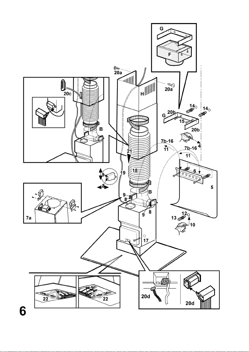
Bild 6
Abluftbetrieb
Die Haube verfügt über einen oberen Luftaustritt B zum
Ableiten der Kü chengerüche na ch außen (Ablu ftrohr und
Rohrschelle n werden nicht geliefert).
Umluftbetrieb
Ist eine Ableitung von Rauch und Kochdämpfen ins Freie
nicht möglich, kann die Haube mit Umluftbetrieb
arbeiten; in diesem Fall muß ein Aktivkohlefilter bzw. ein
Umleitgitter F an der Halterung (Bügel) G montiert
werden; auf diese Weise wird die Luft durch das obere
Gitter H mit Hilfe eines Abluftrohres, das an den oberen
Luftaustritt B angeschlossen ist, und eines
Anschlussrings am Umleitgitter F (Abluftrohr und
Rohrschelle n werden nicht geliefert) rückgeführt .
Modelle ohne Saugmotor funktionieren nur mit
Abluftbetrieb und müssen an eine peripherische
Saugeinheit (nicht mitgeliefert) anges chlossen werden.
Befestigung
Der Abstand zwischen der Abstellfläche auf dem
Kochfeld und d er Unterse ite der Dun stabzugsha ube darf
50cm im Fall von elektrischen Kochfeldern und 65cm im
Fall von Gas- oder kombinierten Herden nicht
unterschreiten.Wenn die Installationsanweisungen des
Gaskochgeräts einen größeren Abstand vorgeben, ist
dieser zu berücksichtigen.
Elektrischer Anschluss
Die Netzspannu ng mu ss der Sp annun g entsp rechen , die
auf dem Typenschild im Inneren der Küchenhaube
angegebenen ist. Wenn die Küchenhaube mit einem
Netzstecker ausgestattet ist, diesen an eine den gültigen
Normen entspre chende , jede rzei t zugä nglich e S teckdo se
anschliessen. Wenn die Küchenhaube nicht mit einem
Netzstecker ausgestattet ist, muss sie direkt an das
Stromnetz angeschlossen werden. Dazu einen
zweipoligen normierten Schalter anbringen, dessen
geöffnete Anschlusstellen mindestens 3 mm
auseinanderliegen müssen (gut zugänglich).
Montage
Die Abzugshaube ist mit Dübeln ausgestattet, die für die
meisten Wände/Decken geeignet sind. Trotzdem sollte ein
qualifizierter Techniker hinzugezogen werden, der
entscheidet, ob die Materialien für die jeweilige
Wand/Decke geeignet sind. Außerdem muß die
Wand/Decke das Gewicht der Abzugshaube tragen
können.
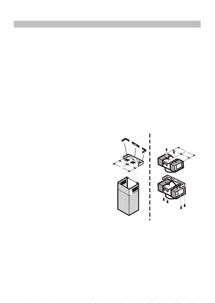
Die Kaminhalterung zusammenbauen (3 Teile):
Die drei Teile müssen mit 4 Schrauben aneinander
befestigt werden, die Größe der Halterung ist regulierbar
und muss der Innenbreite des Teleskopkamins
entsprechen.
Das Umlenkgitter zu sammenbauen (nur wenn ein aus 3
Teilen bestehendes Umlenkgitter mitgeliefert wird - das
Umlenkgitter wird nur für den Umluftbetrieb
verwendet):
Die drei Teile müssen mit 2 Schrauben aneinander
befestigt werden, die Größe des Umlenkgitters ist
regulierbar und muss der Breite der Kaminhalterung
entsprechen, an der es dann befestigt wird.
X
=
G
=
=
X
F
=
X
G
F
H
Bild 5-6
Vor dem Anschluss des Gerätes die Haube mit Hilfe der
Hauptschalttafel der Wohnung stromlos s etzen.
Den/die Fett filter und das Kohlefiltergestell entfernen.
1. Die Sauggruppe auf eine Fläche stellen und den
unteren Hau benteil einschieben.
2. Den Elektroanschluss zwischen den beiden Teilen
vornehmen.
3. Die Haube mit den 12 Schrauben endgültig an der
Sauggruppe befestigen.
4. Mit einem Bleistift an der Wand eine Linie bis zur
Decke kennzeichnen, die mit der Mittellinie
übereinstimmen muss und die Montage er leichtert.
5. Den Bohrplan an die Wand legen: die vertikale
4

Mittellinie des Bohrplans muss mit der an der Wand
gekennzeichneten Linie übereinstimmen; ferner
muss die untere Bohrplankante der unteren Kante
der Haube entsprechen: hierbei ist zu
berücksichtigen, dass die Unterseite der Haube
nach erfolgter Montage bei Elektrokochmulden
mindestens 50 cm bzw. bei Gas- oder gemischten
Kochmulden 65 cm entfernt sein muss.
6. Den unteren Haltebügel so an das Bohrschema
anlegen, dass er sich mit dem vorgezeichneten
Rechteck deckt, die beiden äußeren Bohrlöcher
kennzeichnen und bohren, das Bohrschema
entfernen und zwei Wanddübel einfügen und mit
zwei 5x45mm-Schrauben den Haltebügel der Haube
befestigen.
7. Falls noch nicht montiert, die Ösen mit zwei
Schrauben an den Seiten der Sauggruppe
befestigen (7a). Die Haube am unteren Bügel
einhängen (7b).
8. Die Distanz der Haube zur Wand regeln.
9. Die Haube horizontal ausrichten.
10. Vom Innern der Saugg ruppe aus, mit eine m Bleistift
das Bohrloch für die endgültige Befestigung der
Haube kennzeichnen (1 oder 2 endgültige
Befestigungspunkte notwendig).
11. Die Haube vom unteren Bügel abnehmen.
12. Die gekennzeic hn ete St ell e bohr e n (Ø8m m) .
13. Je nach Bedarf 1 oder 2 Wa nddübel einf ügen.
14. Den Kaminhaltebügel G an die Wand (nahe der
Decke) anlegen, den Kaminhaltebügel als
Bohrschablone benutzen (Sofern vorhanden, muss
das kleine Langloch auf der Halterung mit der vorher
auf der Wand angezeichneten Linie
übereinstimmen) und mit dem Bleistift zwei Löcher
kennzeichnen, die Löcher bohren (Ø8 mm) und 2
Dübel einsetze n.
15. Den Kam inhaltebügel mit 2 Sch rauben 5x45mm an
der Wand fixieren.
16. Die Haube beim unteren Bügel einhängen.
17. Die Dunstabzugshaube definitiv (UNBEDINGT
NOTWENDIG) an der Wand fixieren.
18. Den Rohranschluss zum Ableiten des Rauchs am
Anschlussring an der Oberseite des Saugmotors
vornehmen (Rohr und Rohrschellen werden nicht
mitgeliefert, sondern müss en gekauft werden).
Das andere Rohrende muss bei Abluftbetrieb an
eine Vorrichtung angeschlossen werden, die den
Rauch in Freie leitet. Soll die Haube mit
Umluftbetrieb arbeiten, anschließend das
Umlenkgitter F am Kaminhaltebügel G befestigen
und das andere Rohrende mit dem auf das
Umlenkgitter F ges etz t en Ansc hl uss ri n g verbi nd en.
19. Den Elektroanschluss vornehmen.
20. Die Kamine anbringen und oben mit 2 Schrauben
(20a) an der Kaminhalterung „G“ (20b) fixieren.
Nur für das Modell mit Steuertafel auf dem
Kamin:
Nur fü r den Fall, dass die Steue rtafel noch nicht
auf dem unteren Teil des Kamins angebracht ist:
Führen Sie das vom Motor kommende Flachkabel
durch den Schlitz am Kamin von innen nach außen
(20c).
Verbinden Sie di e Steuertafel mit dem Flachkabel.
Achtung! Der Bolzen am Ende des Flachkabels
MUSS mit dem Loch übereinstimmen, dass sich auf
dem Verbindungssockel an der Rückseite der
Steuertafel befindet.
Nur für den Fall, d ass die Steuertafel scho n auf
dem unteren Tei l des Kamins angebracht ist :
Verbinden Sie die Steuertafel mit dem Steuerkasten
der Dunstabzugshaube.
Achtung! Der Bolzen am Ende des Flachkabels
MUSS mit dem Loch übereinstimmen, dass sich auf
dem Verbindungssockel an der Rückseite der
Steuertafel befindet (20d).
21. Den unteren Kaminteil nach unten gleiten lassen, um
die Sauggruppe vollständig abzudecken und in den
entsprechenden Sitz an der Haube einsc hieben.
22. Das Kaminunterteil mit zwei Schrauben befestigen.
Das Kohlefiltergestell und den/die Fettfilter wieder
einbauen und den ordnungsgemäßen Betrieb der
Haube prüfen.
Beschreibung der Dunstabzugshaube
Bild 1
1. Bedienfeld
2. Fettfilter
3. Griff zum Aushaken des Fettfilters
4. Halogenlampe
5. Dunstschirm
6. Teleskopkamin
7. Luftaustritt (nur bei Umluftbetrie b)
Betrieb
Im Falle einer sehr intensiven
Küchendunstkonzentration die höchste Saugstärke
einschalten. Es wird empfohlen, die Küchenhaube
schon fünf Minuten vor Beginn des Kochvorganges
einzuschalten und sie nach dessen Beendigung noch
ungefähr 15 Minuten weiterlaufen zu lassen.
Modell mit Tastenfeld
A
B
C
D
DCBAE
5

A. Schalter ON/OFF Beleuchtung
B. Schalter ON/OFF der Absaugfunktion und zum
Einschalten der ger i ngs t en Sau gs t ärk e
B+C. Schalter z um Einschalten der mittleren Saugstärke
B+D. Schalter zum Einschalten der maximalen
Saugstärke
E. Funktionskontrolleuchte (bei Modellen mit runden
Tasten)
a
b
c
a. Schalter ON/OFF Beleucht ung
b. Schalter OFF der Absaugf unktion
c. Schalter zum Einschalten der geringst en Saugstärk e
d. Schalter zum Einschalten der mittleren Saugstärke
e. Schalter zum Einschalten der maximalen Saugstärk e
Wartung
Vor sämtlichen Wartungsarbeiten muss die Stromzufuhr
der Küchenh aube unterbrochen werden.
Reinigung
Die Küchenhaube muss sowohl innen als auch aussen
häufig gereinigt werden. Zur Reinigung ein mit flüssigem
Neutralreiniger getränktes Tuch verwenden. Keine
Produkte ver w enden, die Sc heuermittel enthalten.
KEINEN ALKOHO L VERWENDEN!
Zur beachtung: Die Nichtbeachtung der Anweisungen,
die die Reinigung der Dunstabzugshaube und das
Auswechseln und die Reinigung der Filter betreffen,
können Brandgefahr verursachen.
Wir empfehlen daher die folgenden Anweisungen zu
beachten.
Fettfilter
Bild 2
Dieser muss einmal monatlich gewaschen werden (oder
wenn das Sättigungsanzeigesystem der Filter – sofern
bei dem jeweiligen Modell vorgesehen – diese
Notwendigkeit anzeigt). Das kann mit einem milden
Waschmittel von Hand, oder in der Spülmaschine bei
niedriger Temperatur und kurzspülgang erfolgen. Der
Metallfettfilter kann bei der Reinigung in der
Spülmaschine abfärben, was seine Filtermerkmale
jedoch in keiner Weise beeinträchtigt. Zwecks
Demontage der Fett fi lt er B den Aushakgriff ziehen.
Aktivkohlefilter (nur bei der Uml uftversion)
Bild 3
Dieser Filter bindet die unangenehmen Gerüche, die
beim Kochen entstehen.
Der Aktivkohlefilter wird alle zwei Monate (oder wenn das
d
e
Sättigungsanzeigesystem der Filter – sofern bei dem
jeweiligen Modell vorgesehen – diese Notwendigkeit
anzeigt) in warmem Wasser und geeigneten Waschmitteln
oder in der Spülmaschine bei 65°C gewaschen (in diesem
Fall den ollständigen Spülzyklus – ohne zusätzliches
Geschirr im Inneren der Geschirrspülmaschine einschalten).
Das überschüssige Wasser entfernen, ohne dabei den
Filter zu beschädigen; danach das Vlies aus dem
Plastikrahmen entfernen und dieses bei 100° für 10
Minuten in den Ofen legen, um es vollständig zu trocknen.
Das Vlies muss alle 3 Jahre ausgewechselt werden und
weiterhin jedes Mal dann, w enn es beschädigt ist.
Das Gestell, das den Filter trägt, abnehmen, dafür die
Knäufe (g), die es an der Haube befestigen, um 90°
drehen. Das Kohlekissen (i) in den Rahm en (h) schieben
und alles wie der an entsprechender Stelle (j) montieren.
Es besteht die Möglichkeit ei nen traditio nellen Kohlefi lter zu
benutzen, welcher weder gewaschen noch regeneriert
werden kann. Dieser Kohlefilter muss alle 3 bis 4 Monate
gewechselt werden.
Das Kohlefiltergestell und der Filter sind
zusammengeschweißt, das eventuell mit der Haube
mitgeliefert e Gestell ist daher nicht zu verwenden.
Der Kohlefilter wird in die Dunstabzugshaube eingesetzt
und mit den vorgesehenen 2 Plastikschrauben befestigt.
Ersetzten der Lämpchen
Bild 4
Das Gerat von Stromnetz abs chalten.
Hinweis: Vor Berühren der Lampen sich vergewissern,
dass sie abgekühlt sind.
• Mit Hilfe eines kleine n Schlitzschraubenziehers den
Rand des Lämpchens anheben, um dieses
herausziehen zu können.
• Das zu ersetzende Lämpchen entfernen und dieses
mit einer Lampe vom Typ Philips Stan dard Line mit
dem Code 4254 09, mit 12V 20W 30° Ø35 12 V GU4
ersetzen.
• Das Ersetzen und d ie Montage des neuen Lä mpchens
durchführen, indem die beschriebenen Schritte in
umgekehrter Reihenfolg e ausgeführt werden.
Sollte die Beleuchtung nicht funktionieren, erst
kontrollieren, ob d ie Lampen einwandfrei eingedreht sind ,
ehe man sich a n den Kundendienst wendet .
Warnung
Betreiben Sie die Dunstabzugshaube nur mit fachgerecht
eingesetzem Gitter!
Werden in demselben Raum, in dem die
Dunstabzugshaube betrieben wird, gleichzeitig weitere
gas- oder brennstoffbetriebene Geräte verwendet, so muss
in dem Raum ausreichend Zuluft gewährleistet sein.
Wenn die Dunstabzugshaube gleichzeitig mit Geräten, die
nicht mit elektrischer Energie betrieben werden, in Betrieb
ist, darf der Unterdruck des Raumes 4 pa (4 x 10⁻⁵ bar)
nicht überschreiten.
6
Es ist nicht erlaubt, die Abluft in einen in Betrieb
befindlichen Rauch- bzw. Abgaskamin oder Schacht zu
leiten.
Brandgefahr! Flambieren ist unter der
Dunstabzugshaube nicht gestattet!
Offenes Feuer schädig t die Filter der Dunsta bzugshaub e
und kann Brände verursachen. Betreiben Sie die
Dunstabzugshaube daher auf keinen Fall über offenem
Feuer.
Fritieren Sie unter der Dunstabzugshaube nur unter
ständiger Beobachtung, um zu verhindern, dass sich das
erhitzte Öl entzündet.
Die Installation der Dunstabzugshaube ist unter
Beachtung der einschlägigen Vorschriften der
Energieversorgungsunternehmen sowie der
Bauverordnungsvorschriften der Länder vorzuneh men.
Reinigen Sie die Dunstabzugshaube außen und innen
regelmässig.
Es besteht Brandgefahr, wenn Sie die
Dunstabzugshaube nicht regelmässig reinigen und die
Filter nicht wie in der Bedienungsanleitung beschrieben
wechseln.
Für eventuelle Schäden, Brände oder Unfälle, die durch
Nichtbeachten dieser Anleitung entstehen, können keine
Garantieleistungen geltend gemacht werden.
In Übereinstimmung mit den Anforderungen der
Europäischen Richtlinie 2002/96/EG über Elektro- und
Elektronik-Altgeräte (WEEE) ist vorliegendes Gerät mit
einer Markierung versehen.
Sie leisten einen positiven Beitrag für den Schutz der
Umwelt und die Gesundheit des Menschen, wenn Sie
dieses Gerät einer gesonderten Abfallsammlung zuführen.
Im unsortierten Siedlungsmüll könnte ein solches Gerät
durch unsach gemäße Entso rgung ne gative Konseq uenzen
nach sich ziehen.
Auf dem Produkt oder der beiliegenden
Produktdokumenta tion ist folgendes Symbol
durchgestrichenen Abfalltonne abgebildet. Es weist darauf
hin, dass eine Entsorgung im normalen Haushaltsabfall
nicht zulässig ist. Entsorgen Sie dieses Produkt im
Recyclinghof mit einer getrennten Sammlung für Elektround Elektronikgeräte. Die Entsorgung muss gemäß den
örtlichen Bestimmungen zur Abfallbeseitigung erfolgen.
Bitte wenden Sie sich an die z uständigen Behörden Ihrer
Gemeindeverw alt u ng, an de n lokalen Recycl inghof für
Haushaltsmüll oder an den Händler, bei dem Sie dieses
Gerät erworben haben, um wei tere Informationen über
Behandlung, Verwertung und Wiederverwendung dieses
Produkts zu er halten.
einer
7

Instruction on mounting and use
Consult the designs in the front pages referenced in the
text by alphabet lette rs. Closely follow the instructions
set out in this manual. All responsibility, for any
eventual inconveniences, damages or fires caused by not
complying with the instructions in this manual, is
declined.
Use
The hood is designed to be utilized either for suction
version at external evacuation or filtering version at
internal recirculation.
Fig. 6
Ducting version
The hood is equipped with a top air outlet B for discharge
of fumes to the outside (exhaust pipe and pipe fixing
clamps not prov ided).
Filter version
Should it not be possible to discharge cooking fumes and
vapour to the outside, the hood can be used in the filter
version, fitting an activated carbon filter and the deflector
F on the support (bracket) G, fumes and vapours are
recycled through the top grille H by means of an exhaust
pipe connected to the top air outlet B and the connection
ring mounted on the deflector F (exhaust pipe and pipe
fixing clamps not provided).
The models with no suction motor only operate in ducting
mode, and must be connected to an external suction
device (not supplied).
must be strong enough to take the weight of the hood. Do
not tile, grout or silicone this appliance to the wall.
Surface mounti ng onl y.
Assembling the chimney flue support/bracket (3 parts):
The three parts should be fixed with 4 screws, the support
extension is adjustable and should correspond to the
internal width of the telesc opic chimney flue.
Assembling the deflector (only when a deflector
composed of 3 parts is sup plied – the de flector shou ld
be only for the filter version):
The three parts should be fixed with 2 screws, the deflector
extension is adjustable and should correspond to the width
of the chimney flue support, to which it is then fixed.
X
=
G
=
=
X
F
=
X
G
F
H
Installation
The minimum distance between the supporting surface
for the cooking vessels on the hob and the lowest part of
the range hood must be not less than 50cm from electric
cookers and 65cm from gas or mixed cookers.If the
instructions for installation for the gas hob specify a
greater distance, this must be adhered to.
Electrical connection
The electrical tension must correspond to the tension
noted on the label placed inside the cooker hood.
Connect the electrical plug, where provided, to the an
easily accessible outlet in conformity with local standards
in force. Where an electrical plug is not provided (for
direct connection to electrical network) place a standards
approved bipolar switch with an aperture distance of not
less than 3mm (accessible) from the contacts.
Attention: substituting the supply cable must be carried
out by the authorised technical assistance service.
Mounting
Expansion wall plugs are provided to secure the hood to
most types of walls/ceilings. However, a qualified
technician must verify suitability of the materials in
accordance with the type of wall/ceiling . The wall/ceiling
Fig. 5-6
Disconnect the hood during electrical connection, by
turning the home mains switch off.
Remove the grease filter/s and the carbo n filter frame.
1. Rest the suction unit on a flat surface and thread the
lower part of the hood onto it .
2. Make all the electrical connections between the two
parts.
3. Permanently fix the cooker hood to the suction group
with the 12 screws.
4. Using a pen ci l, draw a line on the wall, exte nd ing up to
the ceiling, to mark the centre. This will facilitate
installation.
5. R est the drilling te mplate against th e wall: the vertical
centre line printed on the drilling template must
correspond to the cen tre line drawn on the wall, and
the bottom edge of the drilling template must
correspond to the bottom edge of the hood: bear in
mind that, when insta llatio n is comp lete, the un de rside
of the hood must be at least 50 cm above the cooker
top in the case of electric cookers, and at least 65 cm
above the cooker top in the case of gas or mixed
cookers.
8

6. Place the lower support bracket on the perforation
diagram making it coincide with the traced triangle,
mark the two external holes and perforate. Remove
the perforation diagram, insert two wall-dowels and
fix the support bracket of the hood with two 5x45
mm screws.
7. If supplied dismantled, fix the hooks to the side of
the aspiration group with two screws (7a). Hang the
hood onto the lower brack et (7b).
8. Adjust the distance of the hood from the wall.
9. Adjust the horizontal p osition of the hood.
10. Usin g a pencil mark the cooker hood permanen t drill
hole inside the suction group (1 or 2 fixing points are
necessary for permanent mounting).
11. Remove the hood from the lower bracket.
12. Drill at the point marked (Ø8mm).
13. Insert 1 or 2 wall screw anchors according to
requirement.
14. Apply the flues support bracket „G“ to the wall
adherent to the ceiling, use the flues support bracket
as a perforation diagram (if present, the small slot
on the support must coincide with the line drawn
previously on the wall) and mark two holes with a
pencil. Make the holes (Ø8mm), and insert 2
dowels.
15. Fix the chimney support bracket to the wall using
two 5x45mm screws.
16. Hook the hood onto the bott om br ac ket .
17. Fix the hood into its final position on the wall
(ABSOLUTELY ESSE NTI AL) .
18. Connect a pipe (pipe and pipe clamps not provided,
to be purchased separately) for discharge of fumes
to the connection ring located over the suction motor
unit.
If the hood is to be used in ducti n g ve rsion, the other
end of the pipe must be connected to a device
expelling the fumes to the outside. If the hood is to
be used in filter version, then fix the deflector F to
the chimney support bracket G and connect the
other extremity of the pipe to the connection ring
placed on the deflector F.
19. Connect the electricity.
20. Apply the chimney stacks and fasten them at the top
to the chimney support „G“ (20b) using 2 screws
(20a)
Only for the model with control panel on the flue:
Only if the control panel is not moun ted on the
lower flue:
Insert the small plate of the commands coming
from the motor group into the slot of the flue, from the
interior to the exterior (20c).
Connect the control panel to t he small plate.
Attention! The pin of the small plate terminal
MUST correspond to the hole made in the connection
plinth on the b ack of the cont rol panel.
Only if the contro l panel is alre ady mounted on
the lower flue:
Connect the control panel to the electronic box of the
hood.
Attention! The pin of the small plate MUST
correspond to the ho le made in the connection plinth
on the electr onic box (20d).
21. Slide the bottom section of the chimney down until it
completely covers the suction unit and slots into the
housing provided on top of the hood.
22. Fix the lower section of the chimney with two screws.
Remount the carbon filter frame and the fat/s filter/s and
check the perfect functio ning of the hood.
9

Description of the hood
Fig. 1
1. Control panel
2. Grease filter
3. Grease filter release handle
4. Halogen lamp
5. Vapour screen
6. Telescopic chimney
7. Air outlet (used for filter version only )
Operation
Use the high suction speed in cases of concentrated
kitchen vapours. It is recommended that the cooker
hood suction is switched on for 5 minutes prior to
cooking and to leave in opera tion during cooking and
for another 15 minutes approximately after
terminatin g cooking.
Model with button panel
A
B
C
D
DCBAE
A. on/off light switch
B. on/off aspir ation switch and minimum power selection
B+C. medium power selection aspiration switch
B+D. maximum power selection aspiration switch
E. operating gauge (foreseen in the model with round
buttons)
a
b
c
a. on/off light switch
b. off aspiration switch
c. minimum power selection as piration switch
d. medium power selection aspiration switch
e. maximum power selection aspiration swi tch
d
e
Maintenance
Prior to any maintenance operation ensure that the cooker
hood is disconnected from the power supply.
Cleaning
The cooker hood should be cleaned regularly internally and
externally. Clean using the cloth dampened with neutral
liquid detergent. Do not us e abrasive pr oducts.
DO NOT USE ALCOHOL!
Warning: Failure to carry out the basic standards of the
cleaning of the cooker hood and replacement of the filters
may cause fire risks.
Therefore we recommend observing these instructions.
Grease filter
Fig. 2
This must be cleaned once a month (or when the filter
saturation indication system – if e nvisaged on the mod el in
possession – indicates this necessity) using non
aggressive detergents, either by hand or in the dishwasher,
which must be se t to a low temp erature and a short cycle.
When washed in a dishwasher, the grease filter may
discolour slightly, but this does not affect its filtering
capacity. To remove the grease filter B, pull the spring
release handle.
Charcoal filter (filter version only)
Fig. 3
It absorbs unpleasant odours caused by cooking.
The charcoal filter can be washed once every two months
(or when the filter saturation indication system – if
envisaged on the model in possession – indicates this
necessity) using hot water and a suitable detergent, or in
a dishwasher at 65°C (if the dishwasher is used, select the
full cycle function and leave dishes out).
Eliminate excess water without damaging the filter, then
remove the mattress located inside the plastic frame and
put it in the oven for 10 minutes at 100° C to dry
completely. Repla ce the mattress every 3 years and when
the cloth is damaged. Remove the filter holder frame by
turning the knobs (g) 90° that affix the chimney to the
cooker hood.
Insert the pad (i) of activated carbon into the frame (h) and
fit the whole back into its housing (j).
It is possible to use a traditional carbon filter, neither
washable nor regenerable, to be replaced every 3 - 4
months.
The filter holder frame of the carbon filter is welded
together; the eventual frame supplied with the hood is not,
therefore, to be used.
Insert it into its housing and fix it turning the 2 plastic
knobs.
10

Replacing lamps
Fig. 4
Disconnect the hood from the electricity.
Warning! Prior to touching the light bulbs ensure they
are cooled down.
• Use a small screwdriver as a lever on the borders of
the lamp in order to remove the lightbulb.
• Slide out th e lightbulb to be replaced an d replace with
a new 12V 20W 30° Ø35 12V GU4 PHILIPS
STANDARD LINE code 425409.
• Carry out the replacement and mount the new
lightbulb by following ins tructions in t he reverse.
If the lights do not work, make sure that the lamps are
fitted properly into their housings before you call for
technical ass is tanc e.
Caution
Never use the hood without the grill mounted!
This appliance is designed to be operated by adults.
Children schould not be allowed to tamper with the
controls or play with the appliance .
The premises must have sufficient ventilation when the
kitchen hood is used at the same time as other
apparatuses that use gas a nd other fuels.
The sucked air must not be conveyed in a conduit used
for discharging fume s produced by apparatuses fuelled
by gas or other f uels.
Cooking food on the flame under the hood is severely
prohibited.
The use of open flame damages the filters and can cause
a fire; it must therefore be avoided in any case.
Frying must be carried out under control in order to
prevent overheated oil catching fire.
Keep strictly to the regulations envisaged by the competent
local authority as far as the technical and safety measures
to adopt for discharging f umes are concerned.
The hood is to be cleaned fre quently both internally and
externally.
Failure to observe the regulations about cleaning the hood
and substituting and cleaning the filters can lead to the risk
of fire.
Any responsibility is declined for possible inconveniences,
damage or fire caused to the apparatus deriving from
failure to observe the instructions sho w n in this manual.
This appliance is marked according to the European
directive 2002/96/EC on Waste Electrical and Electronic
Equipment (WEEE). By ensuring this product is dispos ed of
correctly, you will help prevent potential negative
consequences for the environment and human health,
which could otherwise be caused by inappropriate waste
handling of t his product.
The symbol
on the product, or on the documents
accompanying the product, indicates that this appliance
may not be treated as household waste. Instead it shall be
handed over to the applicable collection point for the
recycling of electrical and electronic equipment. Disposal
must be carried out in accordance with local environmental
regulations for waste disposal.
For more detailed information about treatment, recovery
and recycli ng of this product, please contact your local city
office, your household waste disposal service or the shop
where you purchased the pr oduct.
11

Prescriptions de montage et mode d’emploi
Consulter les dessins de la première page avec les
références alphabétiques que l’on retrouvera dans le
texte explicatif.
Suivre strictement les instructions de cette notice. Le
constructeur décline toute responsabilité pour tous les
inconvénients, dommages ou incendies provoquès à
l’appareil et dus à la non observation des instructions de
la présente not ice.
Utilisation
La hotte est réalisée de fa con qu’elle puisse être utilisée
en version aspirante à évacuation extérieure, ou filtrante
à recyclage intérieur.
Fig. 6
Version aspirante
La hotte est équipée d’une sortie de l’air supérieure B
pour l’évacuation des fumées vers l’extérieur ( tuyau
d’évacuation et colliers de fixation non fournis).
Version filtrante
Dans l’éventualité où il ne serait pas possible d’évacuer
les fumées et les vapeurs de cuisson vers l’extérieur, il
est possible d’utiliser la ho tte dans la version filtrante,
en effectuant le montage d’un filtre à char bon actif et d’un
déflecteur F sur le suppo rt (bride) G; les fumées et les
vapeurs sont recyclée s à travers le grillage supérieu r H,
au moyen d’un tuyau d’évacuation connecté à la sortie
d’air supérieure B et à la bague de connexion montée sur
le déflecteur F (tuyau d’évacuation et colliers de fixation
non fournis) .
Les modèles sans moteur d’aspiration fonctionnent
uniquement dans la version aspirante et ils doivent être
connectés à une unité périphérique d’aspiration (non
fournie).
Installation
La distance minimum entre la superficie de support des
récipients sur le dispositif de cuisson et la partie la plus
basse de la hotte de cui sine ne doit pa s être i nférieu re à
50 cm dans le cas de cuisinières électriques et de 65 cm
dans le cas de cuisinières à gaz ou mixtes.Si les
instructions d’installation du dispositif de cuisson au gaz
spécifient une plus grande distance, il faut en tenir
compte.
Branchement électrique
La tension du réseau doit correspondre à la tension
indiquée sur l’étiquette des caractéristiques située dans
la hotte. Si la hotte est fournie avec une fiche, la
raccorder à une prise accessible conforme aux normes
en vigueur. Si la hotte est fournie sans fiche
(branchement direct sur le réseau), la raccorder à un
interrupteur bipolaire normalisé ayant une distance des
contacts supérieure à 3 mm (accessible).
Attention! La substitution du cordon d’alimentation doit
être effectuée par le service d’assistance technique
autorisé.
Montage
La hotte est équipée de che ville s de fixa tio n con venan t à la
plupart des parois/plafonds. Il est cependant nécessaire de
s’adresser à un technicien qualifié afin de s’assurer que le
matériel est approprié au type de paroi/plafond. Le
paroi/plafond doit être suffisamment solide pour supporter
le poids de la hotte.
Assembler le support cheminée (3 parties):
Les trois parties doivent être fixées entre elles avec 4 vis,
l’extension du support est réglagle et doit correspondre à la
largeur interne de la cheminée télescopique.
Assembler le déflecteur (seulement au cas où un
déflecteur composé de trois parties serait fourni – le
déflecteur doit ê tre utilisé u niquement dans la version
filtrante)
Les trois parties doivent être fixées entre elles avec 2 vis,
l’extension du déflecteur est réglable et doit correspondre à
la largeur du s upport cheminée auquel il sera ensuite fixé.
=
G
=
=
X
F
=
X
F
H
Fig. 5-6
Débrancher la hotte, en intervenant sur le tableau
électrique général domestique, pendant les phases de
branchement électrique.
Enlever le/les filtres(s) à graisse et le châssis hors d u filtre
à charbon.
1. Poser le groupe d’aspiration sur un plan puis enfiler
sur celui-ci la partie inférieure de la hotte.
2. Effectuer les branchements électriques entre les deux
parties.
3. Fixer définitivement la hotte au groupe d’aspiration à
l’aide des vis.
4. Au moyen d’un crayon, tracer une ligne sur la paroi,
jusqu’au plafond, en correspondance de la ligne
médiane afin de faciliter les opérations d’installation.
12
X
G
 Loading...