

Page 1
Page 2

Page 3
Stryker M
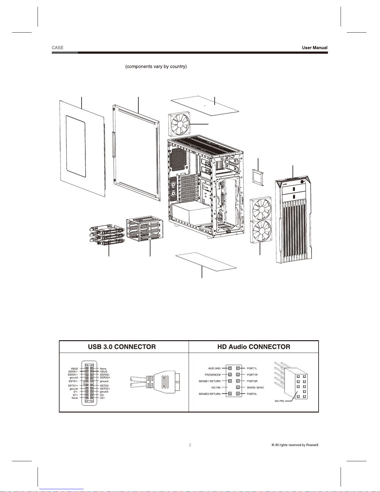
Product Diagram
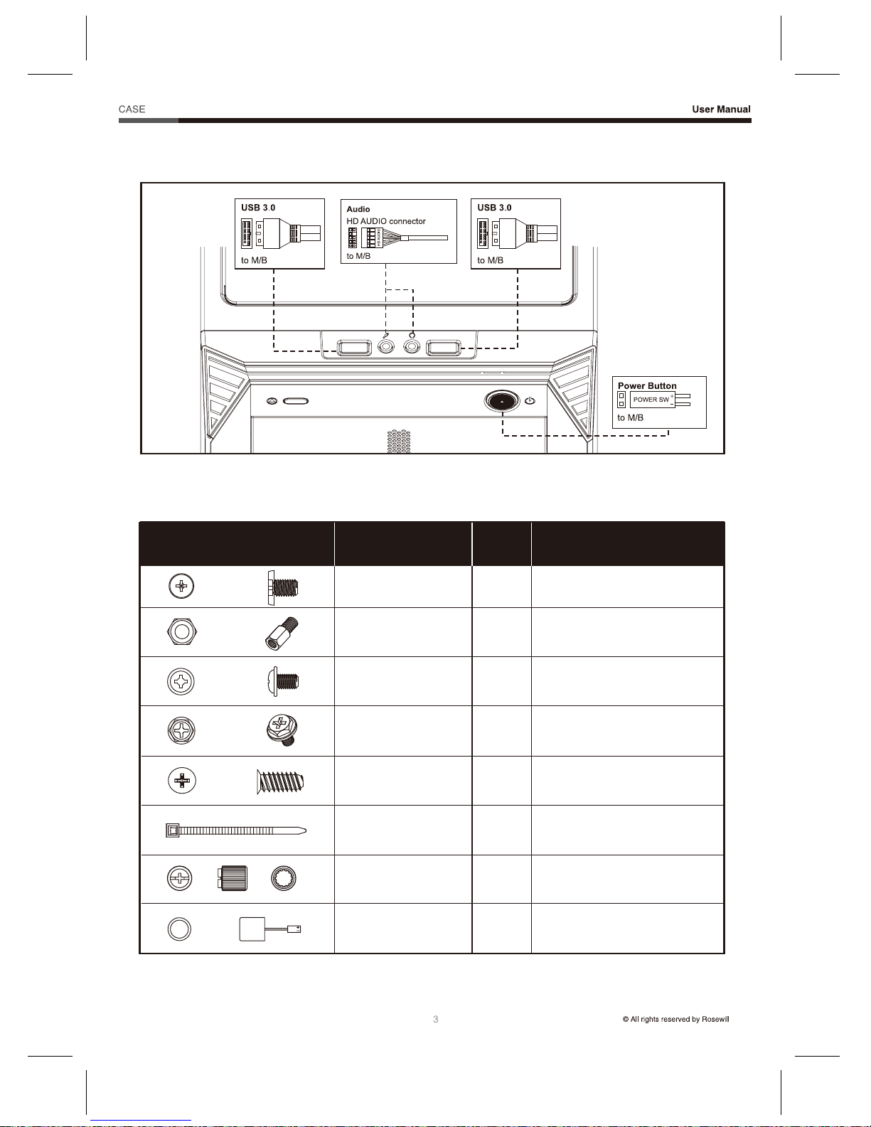
Front I/O Diagram
Accessory Kit
Install the Power Supply
Install the Motherboard
Install the Add-in Card
Install an External 5.25” Device
Install a 3.5”/2.5” Drive
Care
Options
Specifications
10
12
Page 4
Stryker M
Panel L
HDD Tray HDD Cage
Panel R
Product Diagram
Front I/O Pinout
Top Dust Filter
120 mm Fan
Bottom Dust Filter
120 mm Fan x 2
2.5” SSD Tray
Front Panel
Page 5
Stryker M
Front I/O Diagram
Accessory Kit
Figure Part’s Name Used ForQty
Screw-A Motherboard
Motherboard
10
10
Screw-C
Screw-D
Cable Tie
Nut Setter
Buzzer
Standoff
ODD / HDD / SSD
Power Supply Unit
Fan
Cables / Wires
Standoff Installation
Motherboard Alarm
Screw-B
16
4
4
3
1
1
Page 6
Stryker M
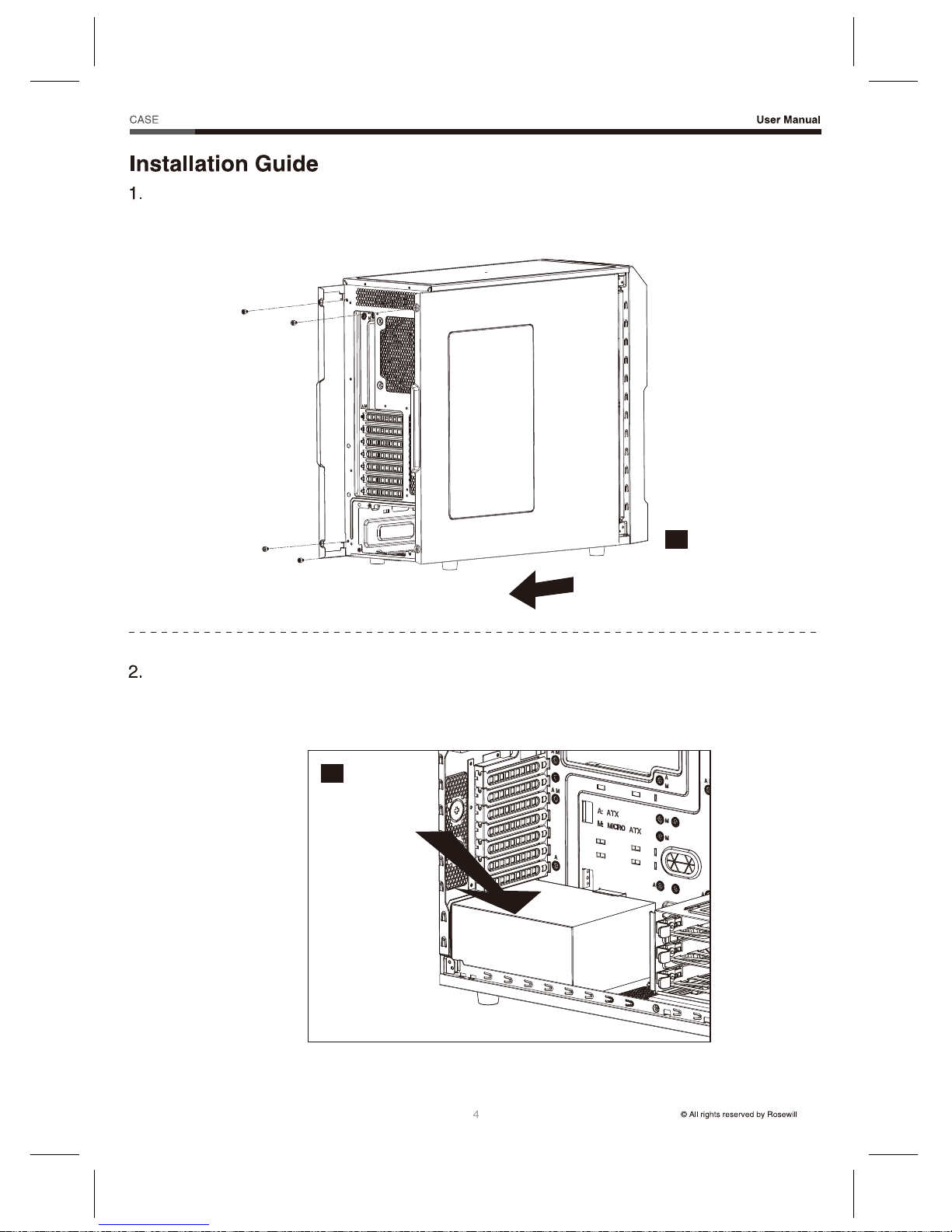
Open the Unit
1-1. Untwist the thumbscrews and slide out panels R and L (Figure 1).
Install the Power Supply
2-1. Seat the power supply unit (PSU) to the bottom of the case and secure with Screw-C (Figure 2).
1
2
Page 7
Stryker M
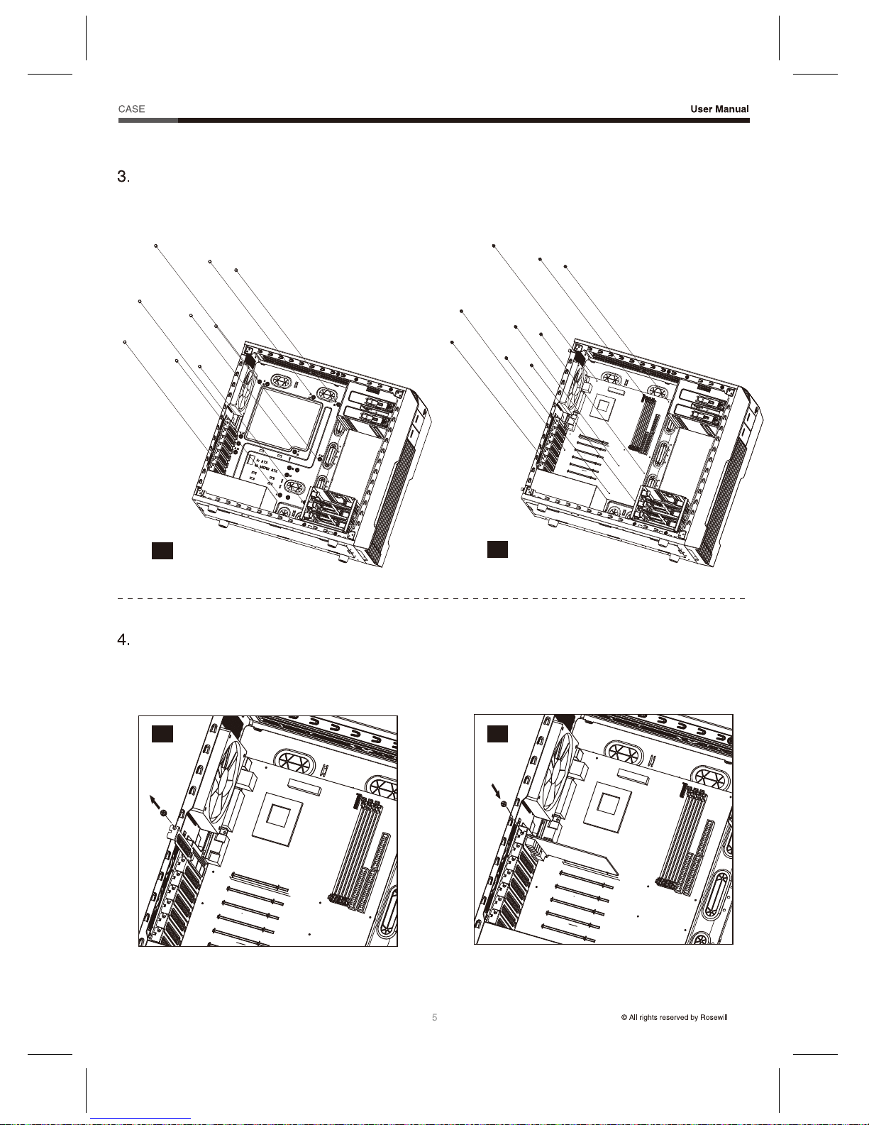
Install the Motherboard
3-1. Line up the standoffs with the screw holes
on the motherboard (Figure 3a).
3-2. Screw the motherboard down with Screw-A
(Figure 3b).
Install the Add-in Card
4-1. Untwist the screws and remove the
slot cover (Figure 4a).
4-2. Install the add-in card and secure with the
Screws (Figure 4b).
3b
3a
4a 4b
Page 8

Stryker M
5. Install an External 5.25” Device
5-1. Pull the front panel out and remove it
(Figure 5a).
5-2. Remove the slot cover (Figure 5b).
5-3. Insert the 5.25” drive and push it back into the case. Make sure it’s secured. (Figure 5c).
5a
5b
5c
Page 9
Stryker M
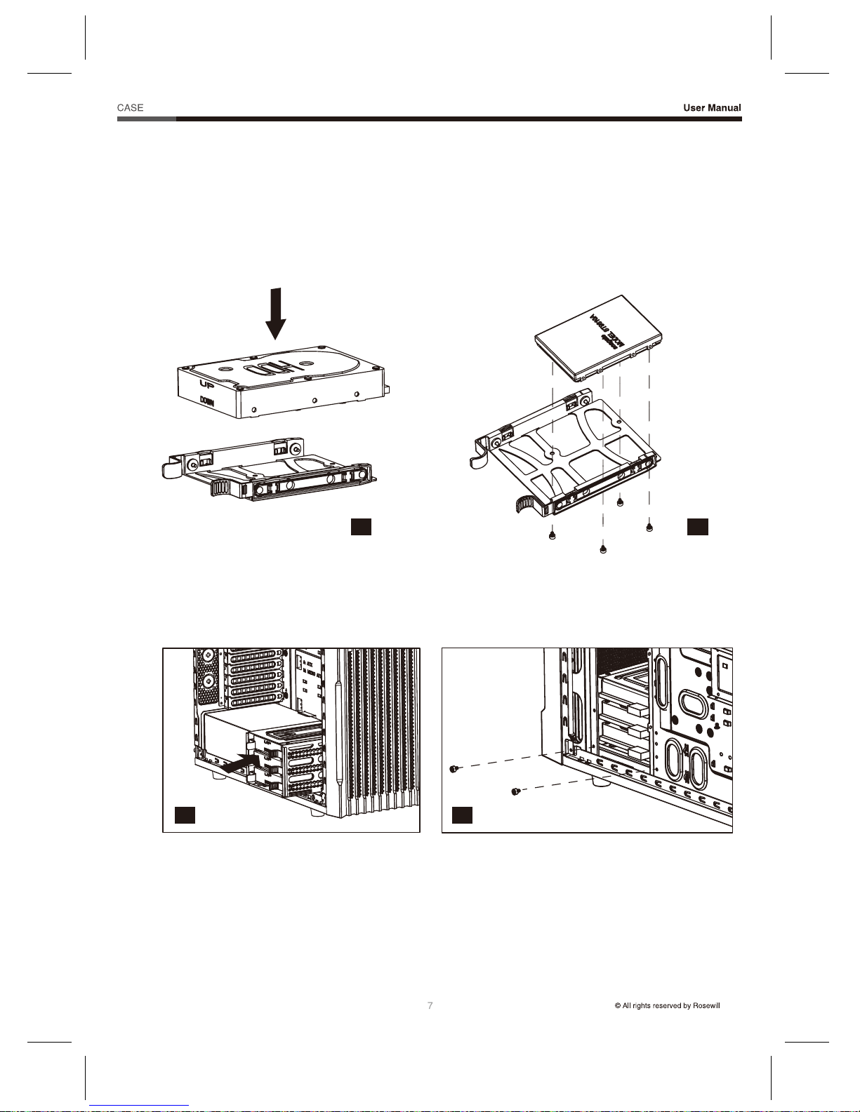
6-1. 3.5” Drive: Install the 3.5” HDD onto the
tray (secure with screws if desired)
(Figure 6a).
6-3. Insert the tray into the HDD Cage (Figure 6c) and secure the cage with screws (Figure 6d).
6. Install a 3.5” or 2.5” Drive
Use Screw-B on drive trays and cages. Refer to the Accessory Kit for reference.
6-2. 2.5” Drive: Screw the 2.5” SSD/HDD onto
the tray with Screw-B (Figure 6b).
6a
6c 6d
6b
Page 10

Stryker M
6-4. An additional 2.5” tray is located in the back of motherboard tray. Unscrew and remove the 2.5”
tray (Figure 6e).
6.5. Secure the 2.5” HDD / SSD onto the tray
with Screw-B (Figure 6f).
6-6. Screw the tray back onto the motherboard
tray (Figure 6g).
6e
6f
6g
8
Page 11
Stryker M
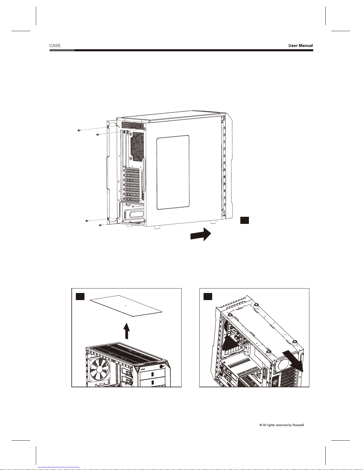
7. Care
To prevent damage, it is recommended to keep all panels closed and secured.
7-2. To prevent overheating and damage, clean the dust filter regularly to ensure adequate airflow
(Figure 7b & 7c)
7-1. Slide the side panels back into place and secure with thumbscrews (Figure 7a).
7a
7b 7c
9
Page 12

Stryker M
8. Options
8-1. Additional Fan Install
8-2. Liquid-Cooling Radiator Install
The Stryker M gives you the option of installing a 240 mm radiator to cool your system.
8-2.1. Front location installation:
a. Remove the front panel.
b. Unscrew to remove the 120 mm fans.
c. Screw the radiator down and return the panel (Figure 8).
8
120/140 mm fans under the top cover (x2)
140 mm fans in the front (x2)
120 mm fan on the bottom cover (x1)
The Stryker M has the capacity for extra fans:
10
Page 13

Stryker M
8-2.2. Top location installation:
a. Remove the top dust filter (Figure 9a).
b. Screw the radiator down and return the filter (Figure 9b).
9a
9b
11
Page 14

Stryker M
9. Specifications
Model
Specs
Model Name
Item Number
Type
Color
Case Material
Power Supply Included
Motherboard Compatibility
With Side Panel Window
External 5.25" Drive Bays
External 3.5" Drive Bays
Internal 3.5" Drive Bays
Internal 2.5" Drive Bays
Expansion Slots
Expansion
Front Ports
Front Ports
120 mm Fans
140 mm Fans
Dimensions
Weight
Physical Specs
Cooling System
Stryker M
11-147-244
Mid Tower
Black
Steel/Plastic
No
ATX, Micro-ATX, Mini-ITX
Yes
2
0
7
3 (0)
1 (4)
USB 3.0 (x2)
Audio In/Out
2 x Front (pre-installed)
2 x Top (optional)
1 x Rear (pre-installed)
1 x Bottom (optional)
2 x Front (optional)
2 x Top (optional)
7.75” x 18.5” x 20.5” (W x H x D)
17 lb.
12
Page 15

Page 16

 Loading...