

Rosewill Shield RSCM-0704B041, Shield RSCM-0708B041, Shield RSCM-0708B081, RSCM-0704B042, Shield RSCM-09166B081 User Manual
Page 1
Page 2
SHIELD DVR User Manual
1
Before you begin
FCC Verification
Note: This equipment has been tested and found to
comply with the limits for Class B digital device,
pursuant to part 15 of the FCC Rules. These limits are
designed to provide reasonable protection against
harmful interference in a residential installation. This
equipment generates, uses and can radiate radio
frequency energy and, if not installed and used in
accordance with the instructions, may cause harmful
interference to radio or television reception, which can
be determined by turning the equipment off and on,
the user is encouraged to try to correct the interference
by one or more of the following measures:
Reorient or relocate the receiving antenna
Increase the separation between the equipment and
the receiver
Connect the equipment into an outlet on a circuit
different from that to which the receiver is
connected
Consult the dealer or an experienced radio/TV
technician for help
These devices comply with part 15 of the FCC Rules.
Operation is subject to the following two conditions:
These devices may not cause harmful interference,
and
These devices must accept any interference
received, including interference that may cause
undesired operation.
DEFAULT PASSWORD INFORMATION
To ensure your privacy, this DVR supports password
protection.
The default username and password:
Username: admin
Password: 123456
To ensure your ongoing privacy, we strongly
recommend setting a password as soon as possible.
Choose something that you will remember, but that
others would be unlikely to guess.
IMPORTANT NOTE:
All jurisdictions have specific laws and regulations
relating to the use of cameras. Before using any camera
for any purpose, it is the buyer’s responsibility to be
aware of all applicable laws and regulations that
prohibit or limit the use of cameras and to comply with
the applicable laws and regulations.
FCC Regulation (for USA): Prohibition against
eavesdropping
Except for the operations of law enforcement officers
conducted under lawful authority, no person shall use,
either directly or indirectly, a device operated pursuant
to the provisions of this Part for the purpose of
overhearing or recording the private conversations of
others unless such use is authorized by all of the parties
engaging in the conversation.
WARNING
Modifications not approved by the party responsible for
compliance could void user’s authority to operate the
equipment.
IMPORTANT SAFETY INSTRUCTIONS
Make sure product is fixed correctly and stable if
fastened in place
Do not operate if wires and terminals are exposed
Do not cover vents on the side or back of the DVR
and allow adequate space for ventilation
Safety Precautions
Do not drop, puncture, or disassemble the
cameras or DVR.
Do not tug on the power adapter. Use the plug to
remove it from the wall.
Do not expose the cameras or DVR to high
temperatures.
For your own safety, avoid using the DVR when
there is a storm or lightning in your area.
Use the cameras and DVR with care. Avoid
pressing hard on the cameras or DVR body.
Do not use the power cable if damaged.
CAUTION
1. TO REDUCE THE RISK OF ELECTRIC SHOCK. UNPLUG
ALL POWER SOURCES, INCLUDING CAMERAS FROM
THE DVR BEFORE REMOVING COVER. FAILURE TO
DO SO CAN RESULT IN DAMAGE TO THE DVR OR ITS
COMPONENTS AS WELL AS INJURY OR DEATH.
2. WARNING: TO PREVENT FIRE OR SHOCK HAZARD,
DO NOT EXPOSE THIS UNIT TO RAIN OR MOISTURE
3. TO PREVENT ELECTRIC SHOCK, MATCH WIDE BLADE
OF THE PLUG TO THE WIDE SLOT AND FULLY
INSERT
4. WHEN WORKING WITH ELECTROSTATIC SENSITIVE
DEVICES SUCH AS HARD DISK OR DVR UNIT, MAKE
SURE YOU USE A STATIC-FREE WORKSTATION. ANY
ELECTROSTATIC ENERGY COMING IN CONTACT
WITH THE HARD DISK OR DVR CAN DAMAGE IT
PERMANENTLY.
Page 3

SHIELD DVR User Manual
2
Congratulations o n your SHIELD DVR System Purchase!
SHIELD - Rosewill makes high quality home safety and security products and also easy for installation. We
are devoted to bringing safety to you, your family, property and business with our SHIELD product line. With
SHIELD - Rosewill video security system, you are able to keep a watchful eye on the things you wish to
protect.
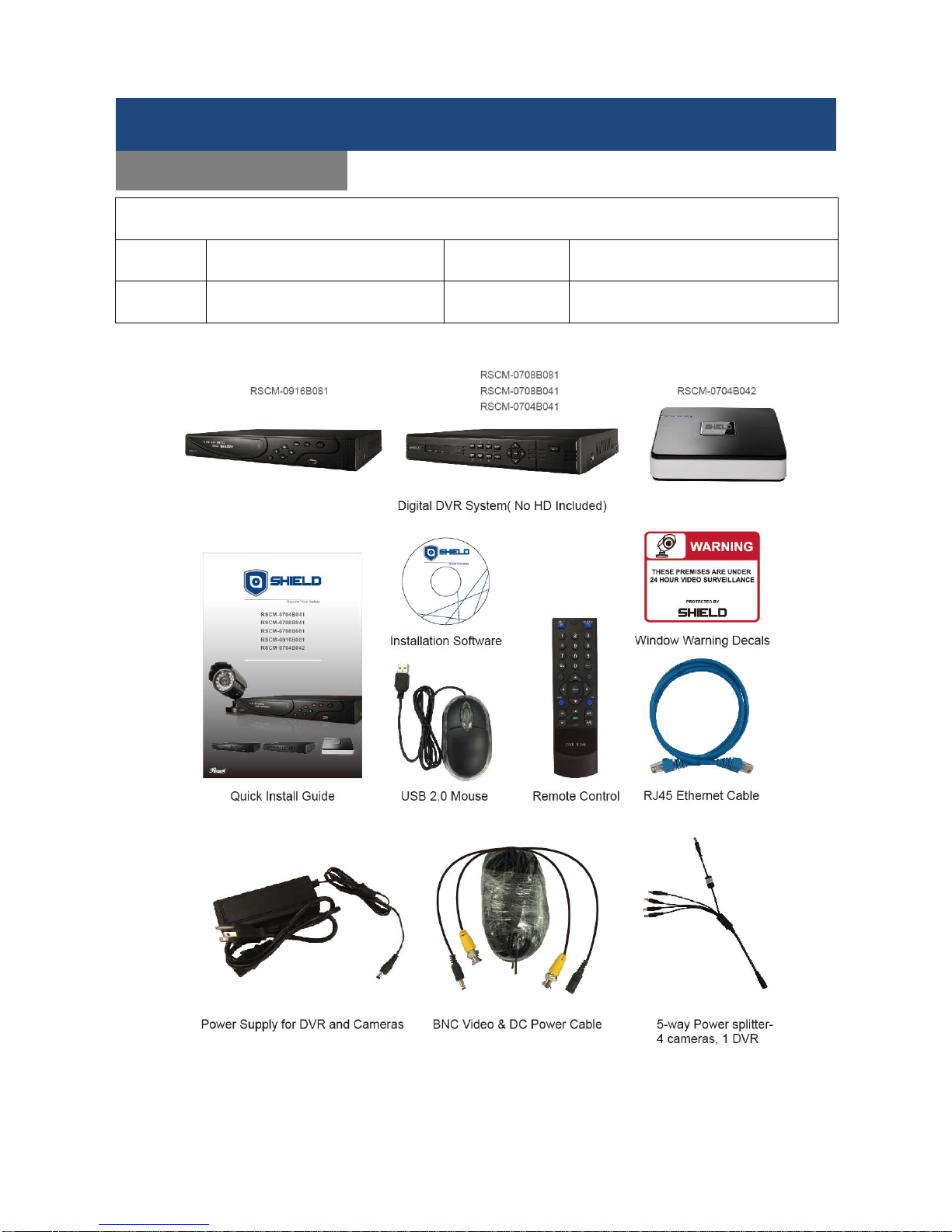
The manual is written for the following SHIELD products:
- RSCM-0704B041
- RSCM-0704B042
- RSCM-0708B041
- RSCM-0708B081
- RSCM-0916B081
To be an outstanding and leading company in security systems, SHIELD will continue to improving with more
functions or stability to better secure your family and business. Hence, some on-screen displays may change.
If you have any doubt during installation, please feel free to visit our website at www.rosewill.com
for the latest
manuals or firmware updates.
Before you begin
SHIELD - Digital Video Recorder
Page 4

SHIELD DVR User Manual
3
This is a 4/8/16 C hannel H.264 digital video r ecorder with free Linux OS and provides rem ote live viewing,
motion detection, PTZ support (requires a compatible with PTZ camera), and alert notification (not for
RSCM-0704B042). This DVR s ystem is suitable for home, commerc ial, business/retail, sm all warehouse, or
many more environments.
Features
4CH/8CH/16CH real-time/live view/recording/playback
Pentaplex mode: Live view, recording, playback, backup, network and mobile phone surveillance
simultaneously
Support HDMI, CVBS, and VGA output simultaneously
Dual Stream support, Main stream supports encoding at up to D1-real time , sub stream at CIF/QCIF
Various recording modes: Scheduled, manual, motion detected
Smart video detection: MD (motion detection), camera blank, video loss
Various searching modes: Time/calendar, events (alarm, motion)
Powerful remote surveillance, playback, recording, control, menu setup, recording backup.
Alarm triggering screen tips, buzzer, PTZ, e-mail & FTP upload
Mobile device support such as iPhone, iPad, Andr oi d, etc.
Multi-user log in support
Support PTZ control with preset, cruise and trac k scans
Support SATA HDD(not included, up to 4TB)
Up to 1 SATA HDD
Up to 2 SATA HDD
Model
RSCM-0704B041, RSCM-0704B042, RSCM-0708B041,
RSCM-0704B081
RSCM-0916B081
Support multi- languages such as English, French, Russian, Spanish, German, and etc.
Product Introduction
Digital Video Recorder
Page 5

SHIELD DVR User Manual
4
Description
Page
Before you begin
2
Product Introduction
3
Getting started
5
Product Overview
6
Front Panel
6
Rear Panel
7
Remote Control
8
Mouse Control
9
What’s in the Box
10
Connection Diagram
11
Initial Installation
13
HDD Installation
13
System Installation
14
Startup Wizard
15
Basic Setup
17
System Startup
18
Menu Functions
19
Main Menu Access
19
CONFIGURATION
20
SYSTEM
21
RECORD
22
NETWORK (BASIC SETTINGS)
23
NETWORK (ADVANCED/DDNS)
24
NETWORK (Port Forwarding)
25
NETWORK (NTP)
26
ALARM
27
ACCOUNT
28
ABNORMITY
30
MAINTAIN
31
SEARCH
33
OUTPUT
35
STORAGE
38
SHUTDOWN
40
Advanced Settings
41
PTZ Setup and Control
41
PTZ Camera Setup and Control
43
DVR Firmware Update
44
Remote Surveillance
46
Remote Login
46
LIVE VIEW WEB INTERFACE
47
LIVE VIEW SYSTEM OPERATION
48
LIVE VIEW SYSTEM CONFIGURATION
50
Reference
52
VOICE INTERCOM
52
Hard Disk Redundancy
52
HDD S.M.A.R.T
53
TERMS
54
HDD CAPACITY CALCULATION
55
COMMON FAULTS
57
INTERNET EXPLORER CRASH
58
Content
Page 6

SHIELD DVR User Manual
5
How to Read This Lon g Manual
This is a big and detailed user manual, but you won’t have to read all of it. You can read the QIG we provided
in the box first to setup you r DVR system . It can tak e a few hours to c onnect ever ything and run t hrough the
setup procedure.
This big manual is for users who want to get everything out of the DVR’s capabilities, while the DVR is
seriously configurable, the out-of-the-box settings do a great job in 90% of situations, but some users will want
to get into every detail, so that information is presented for those who need it.
The Basic Setup
You can finish most basic installation of the DVR by following the steps in QIG
To get the most out of your hard drive, we suggest that you configure your DVR to record only when it detects
motion – that way, you won ’t fill the hard drive with uneventful video.
Before installing anything, connect the DVR and cameras and test your system for functionality. We
ensure everything is working prop er ly when we ship th em out, but some time s thi ngs c an be da maged
in transport, and occasionally components may fail. It is better to find out now, before everything is
fixed in place.
Start the DV R Setup
There are 3 steps to getting your DVR set up. If you want to use the default settings, you’ll only need to
complete step 1 and 2.
1. Connecting the DVR(see the connection diagram from P10~12)
2. Follow the QIG we attached in the Box
3. Optional: Follow the DVR Menu Functions to complete additional functions.
Getting started
Page 7
SHIELD DVR User Manual
6
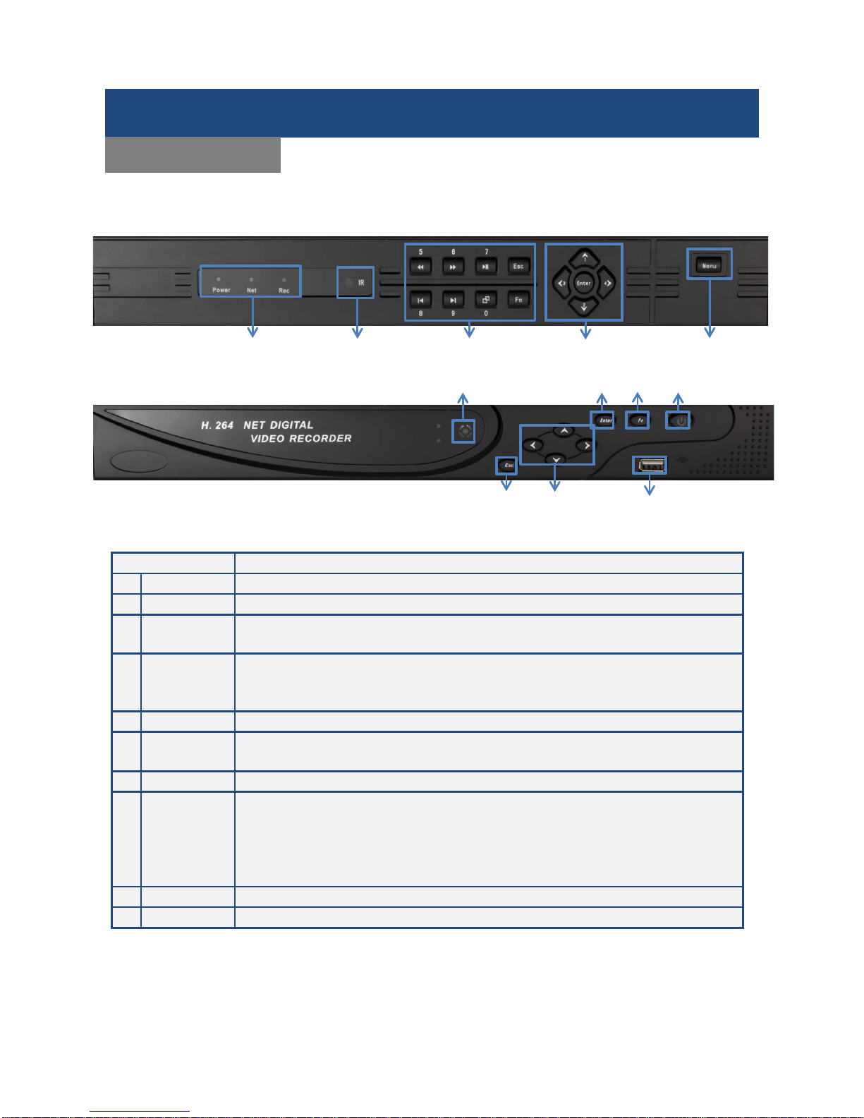
RSCM-0708B041/RSCM-0708B081/RSCM-0704B041
RSCM-0916B081
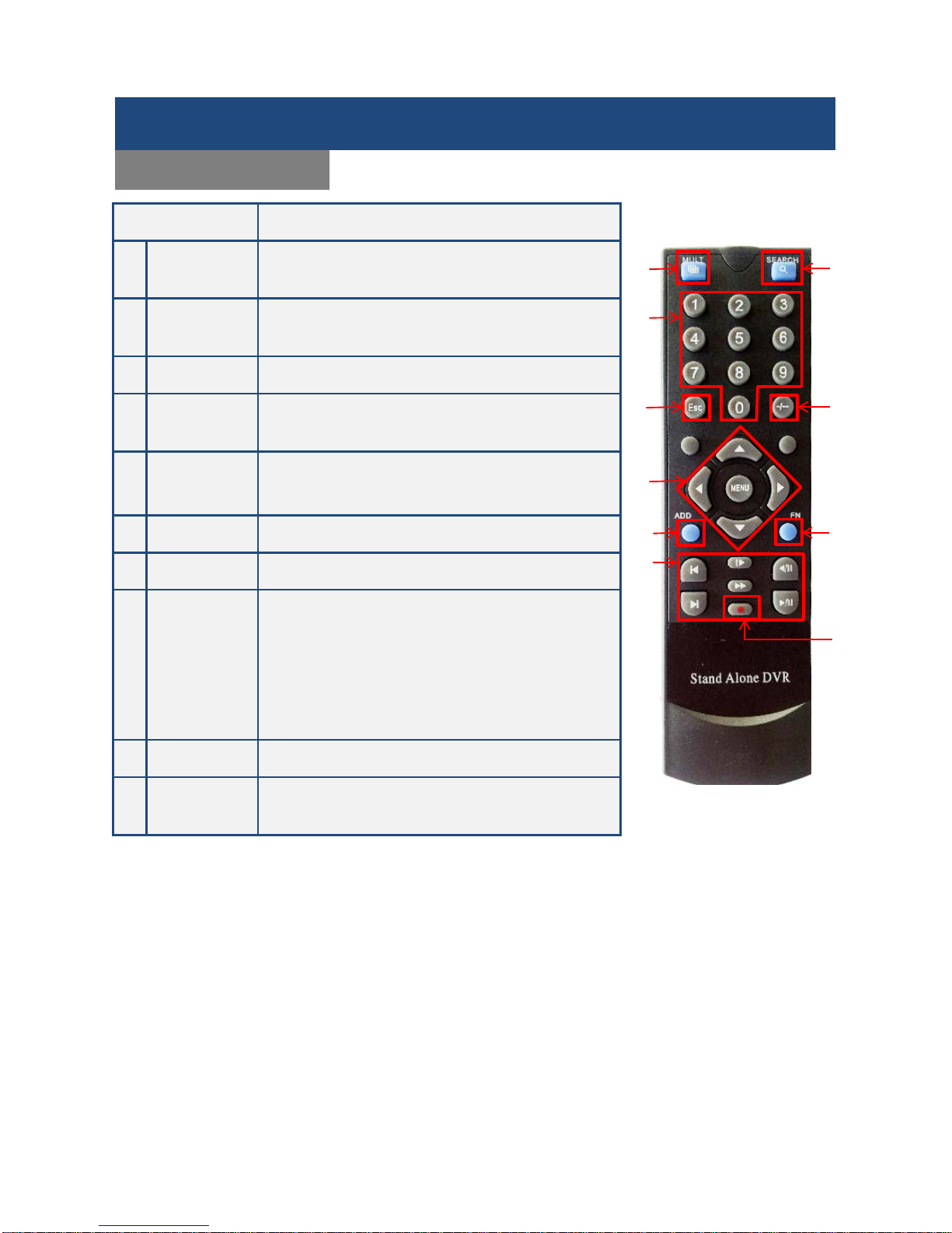
Name
Function
1
Indicators
Power On/ Network /Recording Active
2
IR/Ext.IR
Receives signals from the remote control
3
Functional
Keys
Function keys, and the corresponding number key to switch or exit the function keys
4
Directional
keys
Directional controls: Up/Down can jump up or down. Activates the digital input box to
increase or decrease a number.
Left/Right: Switches screens Enter: Operation confirmation
5.
Menu
Click to enter the MENU configuration
6 Esc
Back to previous menu, operation cancel;
Back to live view when playing back records.
7
Enter
Operation confirm; Switch to default button; Menu configuration.
8 Fn
Single screen view: PTZ control and im age color ;
Setup motion detection area: “Fn” with direction keys;
Clear function: long press “Fn”(≥1.5 seconds) to clear all content in edit box;
Switch typing methods by “Fn” when select a textbox;
Cooperate with menu tips.
9
ON/OFF
Power on/off operation.
10
USB
USB 2.0 Port for mouse or external devices
Product Overview
Front Panel
1
2
3
4 5 2 6 4
7
8
10
9
Page 8
SHIELD DVR User Manual
7
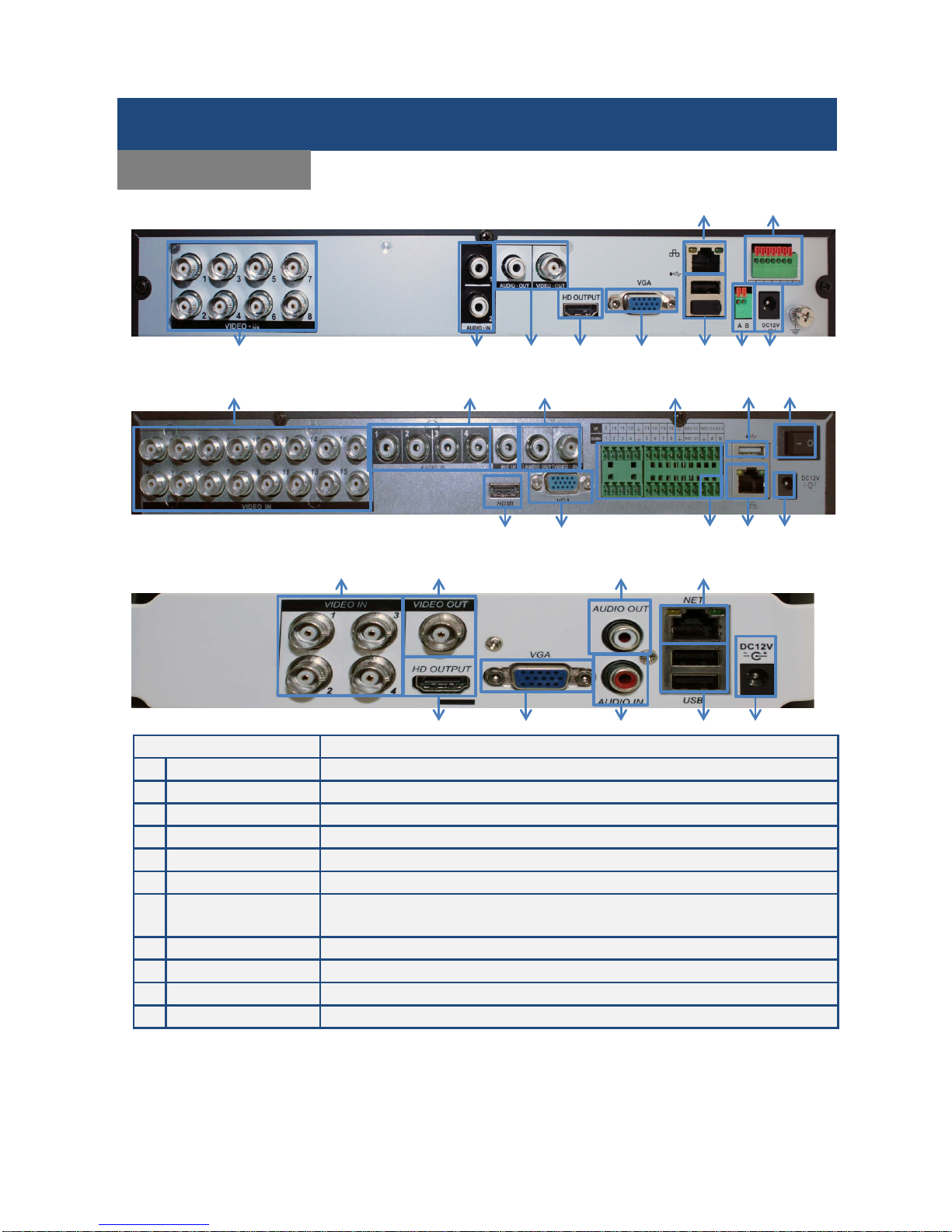
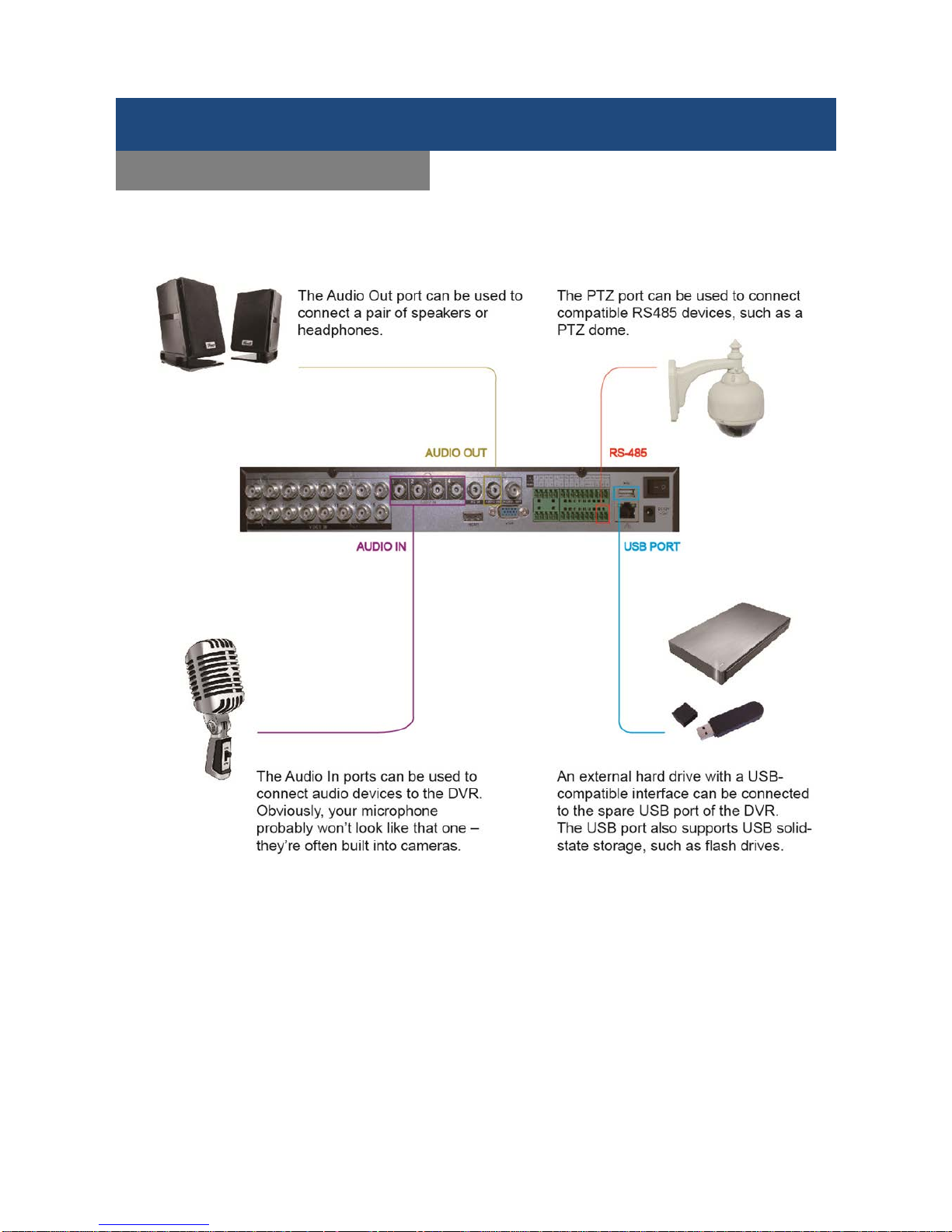
RSCM-0704B041/ RSCM-0708B041/ RSCM-0708B081
RSCM-0916B081
RSCM-0704B042
Name
Function
1
Video Input
COMPOSITE VIDEO SIGNAL (CVBS) INPUT INTERFACE.
2
Audio Input
AUDIO INPUT INTERFACE.
3
Video/Audio Output
COMPOSITE VIDEO/AUDIO SIGNAL (CVBS) OUTPUT INTERFACE.
4
HDMI Output
HD OUTPUT INTERFACE.
5
VGA
VGA OUTPUT INTERFACE.
6
Network
RJ-45 INTERFACE.
7 USB Port
USB2.0 PORT.
Note: the bottom USB port is not available. (RSCM-0704B041/RSCM-0708B041/RSCM-0708B081)
8
RS485 Port
RS-485 INTERFACE (Applied with PTZ Camera)
9
Power Input
DC 12V.
10
I/O Ports
ALARM INPUT/ OUTPUT.(OPTIONAL)
11
Power Switch
Turn on/off the DVR main power.
Product Overview
Rear Panel
1
2
3 4 5 7 8
9 6 10 9 1 2 3 4 5 7 8
6
10
11
1 3 3 4 5 2 6 7 9
Page 9
SHIELD DVR User Manual
8
Name Function
1
Multi-window
button
Split screen view
2
Numeric
buttons
Code input/number input/channel switch
3 Esc Exit button
4
Navigation
buttons
Up ,Down, Left, Right and Enter/ Men u but to n
5
Record/
Playback
control
Control playback of recordings
6 Record mode Manual “record mode”
7 ADD Input the number of camera to add a camera
8 FN
Press to enter
Single screen view: PTZ control and im age color ;
Setup motion detection area: “Fn” with direction keys;
Clear function: long press “Fn”(≥1.5 seconds) to clear
all content in edit box;
Switch typing methods by “Fn” when select a textbox;
Cooperate with menu tips
9 Search Search recorded files
10
Number
switching key
Input the numbers greater than 10
Note: RSCM-0704B042 is not equipped with the remote control.
Product Overview
Remote Control
1
2 3 5
4
7
6
8
9
10
Page 10
SHIELD DVR User Manual
9
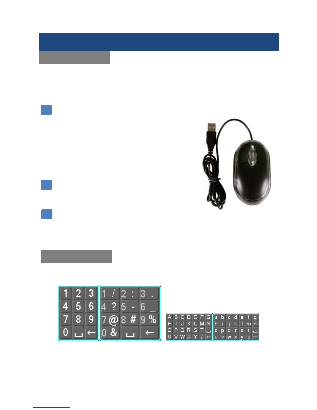
This system also has a virtual k eypad function where users c an input letters or num bers. You can switch as
the way like your sm artphone: 1.numbers, 2.upper case (ABC) and 3.lower case (abc). Not e you can acces s
all numbers when in the “Letters” virtual keypads. See below.
Left Click
Left click the mouse on the Options icon to enter the menu
Click the exact instruc tions to contr o l
Change the state of check boxes and dynamic detection blocking
Click the combo box and a drop-down list will pop up
Under 3D P/T/Z control mode, c lick the mouse and drag to the
lower right, this will ena ble 3D P/T/Z contr ol. Drag fr om the lower
right to upper left to make 3D P/T/Z control narrow. For more
details refer to Sect ion 5.4 P/T /Z
Select and confirm or open, for example: double-click on playback
video
Right Click
Pop up the context menu under the monitor screen
Exit without saving while in the menu interface
Scroll Wheel
Increase or decrease a value while in the Switch combo box
options
Move up and down in a list box
Zoom in and out in P/T/Z 3D zoom mode
Product Overview
Mouse Control
In addition to the front panel keys and remote control, you can also connect a mouse to a USB port
to control the On-Screen Display (OSD) menu functions. The following section describes the
mouse functions.
Virtual Keypad
Numbers/Symbol Switch
Uppercase/Lowercase Switch
1 2 3
Page 11
SHIELD DVR User Manual
10
1* DVR system depends on which one your purchase.
(RSCM-0916B081, RSCM-0708 B0 81, R SC M-0708B041, RSCM-070 4B0 41, RSC M-0704B042)
1* QIG 1* CD 1* Mouse 1* Remote control
(Not equipped in RSCM-0704B042)
1* RJ45
cable (6ft)
1* Power adapter for DVR &
cameras( Power output: 12V5A)
1* BNC and DC
power cable
1* 5 way power splitter
(4 cameras + 1 DVR)
When you unpack the DVR, you should find the following items in the box. If anything is missing please notify
your place of purchase.
Product Overview
What’s in the Box
(Not equipped in
Page 12
SHIELD DVR User Manual
11
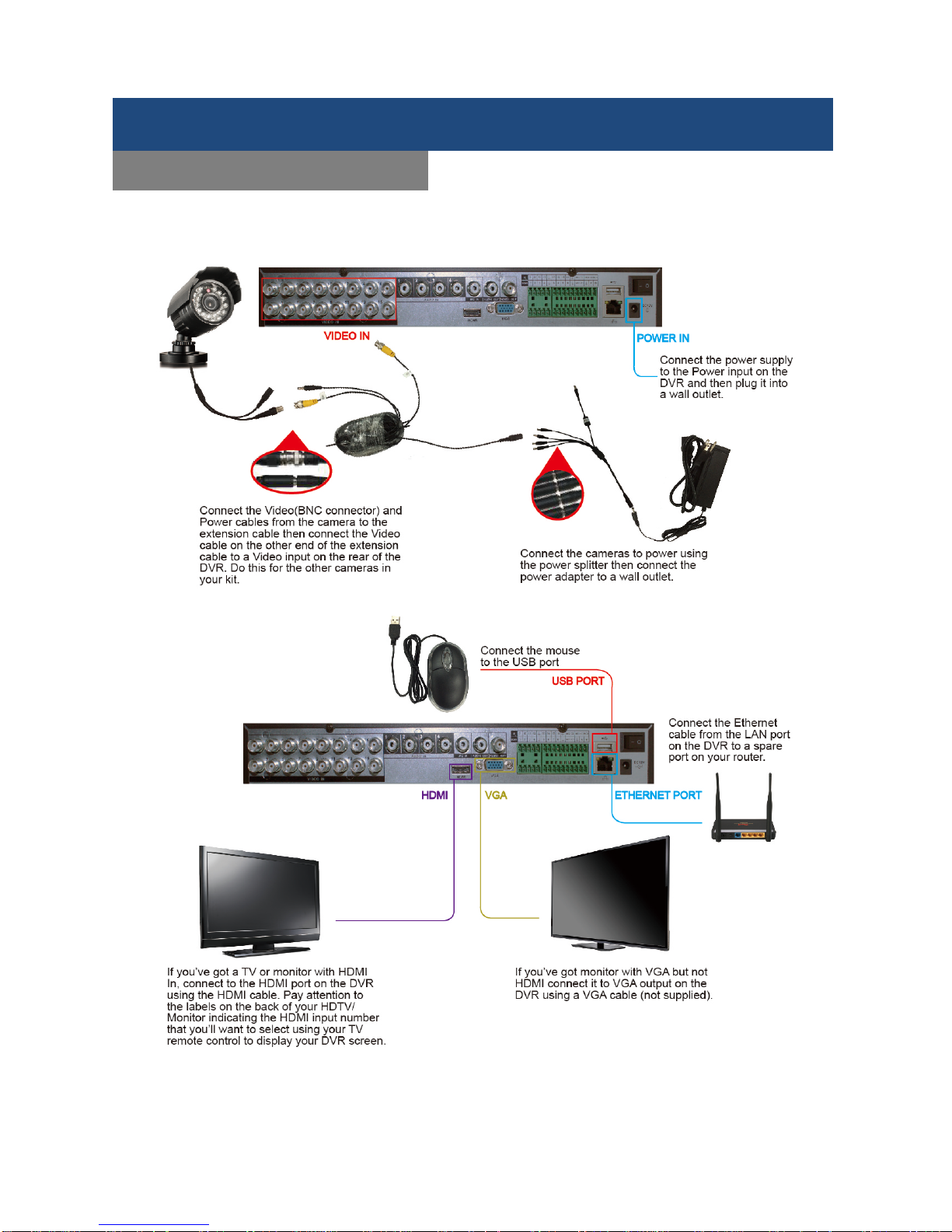
In the connection diagram, we take RSCM-0916B081 as an example. Users can assemble other models
(RSCM-0916B081, RSCM-0708B081, RSCM-0708B041, RSCM-0704B041, RSCM-0704B042) based on this
connection diagram.
Product Overview
Connection Diagram (1/2)
Page 13
SHIELD DVR User Manual
12
Product Overview
Connection Diagram (2/2)
Page 14
SHIELD DVR User Manual
13
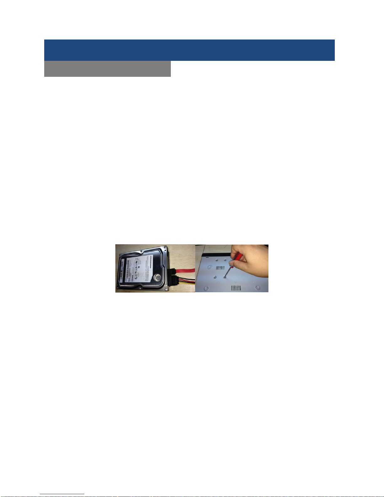
Tools & Preparation
You will need a Philips-head screwdriver and a hard disk drive to install inside the DVR housing.
Hard Disk Drive (HDD) Specifications: 3.5-inch SATA hard disk drive (up to 4TB).
Installation Steps
Make sure to take precautions against static electricity discharges when installing the HDD. Static discharge
could damage the drive and the internal components of the DVR. To reduce this risk, it is best to work on an
anti-static mat and use a grounding wrist strap.
1. Use a Philips-head screwdriver to remove the DVR’s external metal housing by removing the two screws
on each side of the housing and the one at upper back edge. Set the screws aside to be used for reassembly.
2. The HDD will have mounting holes on the underside of the drive and these should line up with the mounting
holes in the bottom of the DVR. Orient the drive so that the power and data cable connectors are facing the
front of the DVR and align the mounting holes on the HDD with the mounting holes in the bottom of the DVR.
Use the supplied screws to fasten the HDD to the DVR’s metal frame by inserting the screws from the outside
of the DVR through the housing and then screw them into the HDD’s mounting holes. To avoid undesirable
results, it is important that the HDD be securely mounted to the DVR.
3. Connect the power and data cables from the DVR circuit board to the HDD. The connectors are of different
sizes and are keyed for easy and correct placement.
4. Replace the DVR external metal housing and secure it with the housing screws.
Note:
The capacity of the HDD determines how much video can be recorded in addition to whatever DVR
parameters (recording or encoding setup) have been set to make the recording. Refer to section 5.10 in
Chapter 5 of this manual for more information.
Initial Installation
HDD Installation
Page 15

SHIELD DVR User Manual
14
Preparation
Before you integrate the DVR into a complete surveillance system, you will need to assemble all the
necessary components and connecting cables. These include cameras with their power adapter(s) and
connectors, a video display monitor to display the camera video feed, and connecting cables for all devices.
Connecting the DVR
To connect the DVR to the other components in the surveillance system you will need to do the following:
1. Place the DVR on a flat stable surface and connect the cameras to the video input jacks on the back
panel.
2. Connect the VGA video output port to the system display monitor.
3. Connect a network cable to the RJ45 network interface for connecting to a LAN or other network.
4. Connect the supplied USB mouse to one of the USB 2.0 ports on the rear panel of the DVR.
5. Plug in the AC power adapter into the power jack on the rear panel of the DVR.
Caution:
For an external alarm device or PTZ camera, please refer to its relevant instructions.
The DVR power cords should be placed under all other wires and connected correctly.
Initial Installation
System Installation
Page 16
SHIELD DVR User Manual
15
After you finish connecting your DVR devices and power on the DVR, you may first see the screen below.
This is a Startup Wizard which will lead you to the remote viewing via your smartphone and network
configuration.
Step1. HELP
1. You can scan the QR code based on different types of your smartphone, and start to download and inst a ll
the IMSeye. IMSeye is an App in which you can view your D VR remotely.
2. Users can also see the device ID of P2P in the same screen which is fixed (Users are not able to change it),
and can change the password in here.
Startup Wizard
1. HELP
Page 17
SHIELD DVR User Manual
16
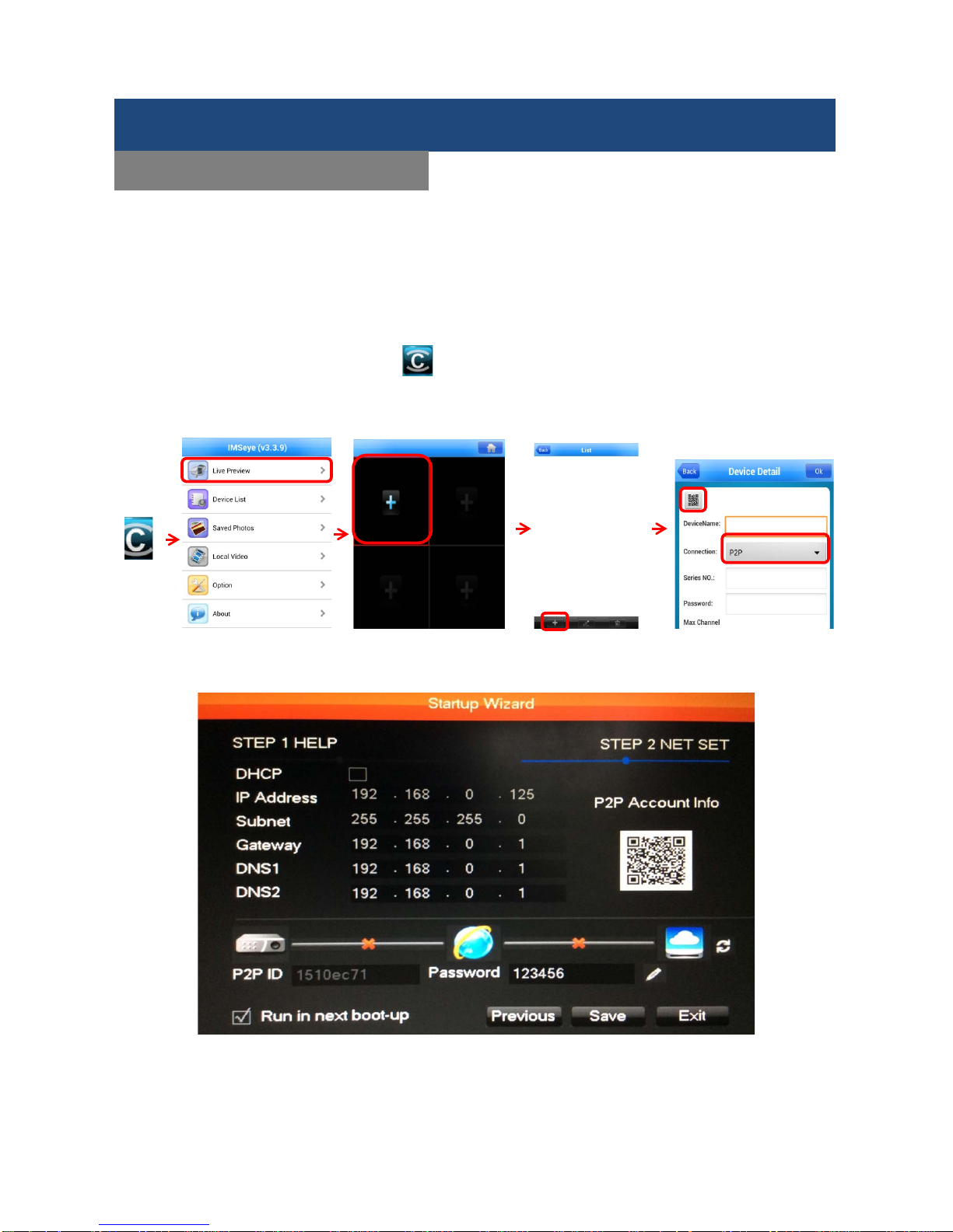
Step2. NET SET
Here to setup your network configuration.
1. If your network belongs to DHCP, please check the box of DHCP. The network will search for the IP
address automatically.
2. if your network belongs to Static IP, you need to fill out the IP Address, Subnet, and Gateway provided by
your ISP into the box
3. For P2P Info, you need to open IMSeye you just download to your smartphone. Click on LivePreview,
and + , then change the connection to P2P and press at the upper left corner of screen to scan the QR
code below to start setup your network via your smartphone.
After the configuration is done, you can then press Save to go back to the LiveView screen. For further
detailed settings, please look up the user manual.
Startup Wizard
2. NET SET
Page 18
SHIELD DVR User Manual
17
LiveView Screen
After completely connecting the hardware of the DVR, you can start the LiveView Screen from the front panel
of DVR, the remote control, or the USB mouse.
If the DVR is installed correctly and the switch is set to “ON” with the power light on, the DVR will boot up
automatically. Different models may have varying boot-up processes, please refer to the Front Panel
Introduction.
The DVR will detect all of the connected hardware after booth up. The DVR will output an audible alarm and
enter the LiveView Screen in which you can check the Main Menu by right clicking on the LiveView Screen
with a connected mouse to access further settings.(default login: Username: admin; Password: 123456)
The Recording starts when the DVR is powered up, because the DVR is set to automatically start recording
when the power is switched on.
Camera Recording
Video Feed Lost
Motion Detection Activated
Channel Lock
Allows screen to switch polling
Basic Setup
System Startup
LiveView Screen
Right click on the screen, and enter
Main Menu for further settings.
Page 19
SHIELD DVR User Manual
18
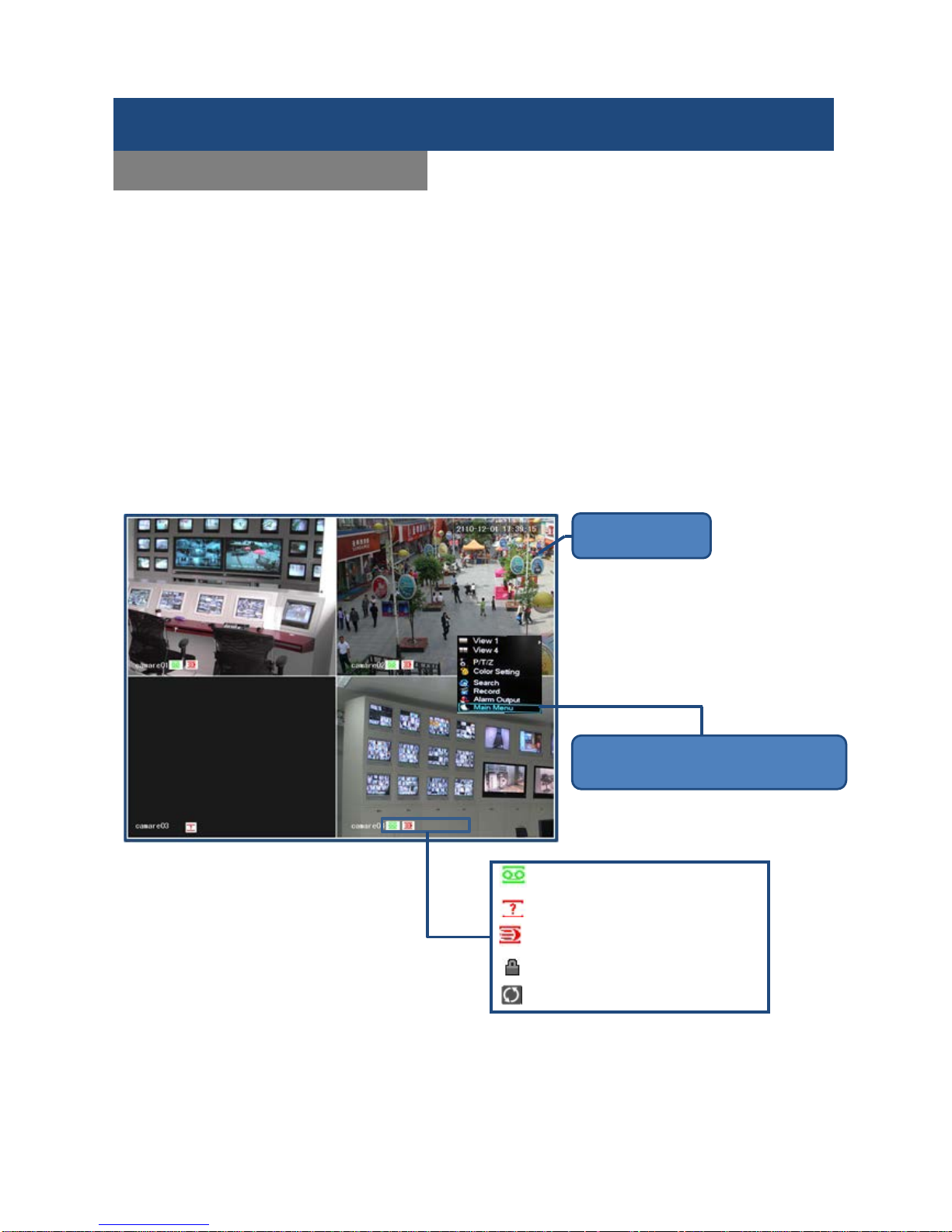
1. Viewing Mode
A maximum of 4 channels can be dis played on one monitor at
one time. The operator can choose to display one or four
channels.
2. P/T/Z
Set P/T/Z protocol, baud rate or address bits. For details on
doing this, refer to P39.
3. Color Setting
Users can adjust color s of the image, hue, brightnes s, contrast,
and saturation here. Se t all the inform ation based on 2 differ ent
periods according to the local time. For each adjustment, the
device will automatically switch to the best video quality.
4. Search
Search for records by type, channel, time and playback.
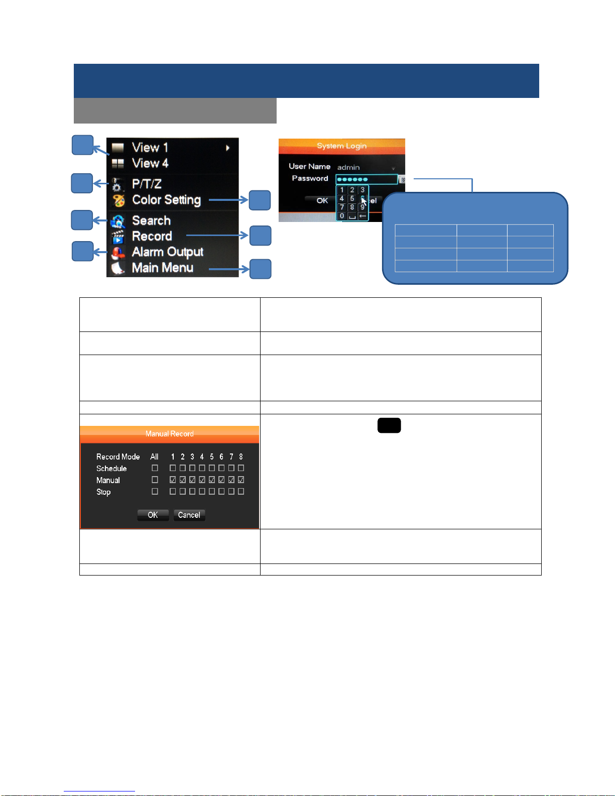
5. Record
Tap Record or press the (red dot) record button on the
remote control. This will bring up the manual recording interface.
There are 3 recording options: Schedule, Manual, and Stop.
You can pick any of them to start recording, and if you pick
Manual then it will record right away.
6. Alarm Output
There are 3 alarming options: Schedule, Manual, and Stop. You
can pick any of them to setup the alarm output. If yo u select the
Manual mode, the DVR will alarm immediately.
7. Main Menu
You can click on the Main Menu for further settings.
Note: An alarm will occur if a password is entered incorrectly three times. The system will be locked for 30
min after 5 unsuccessful login attempts.
Note: The power supply must match the DVR, substituting it is not recommended.
Basic Setup
System Startup
●
If you log in Main Menu, you will need to
enter the Password.
User Type
User Name
Password
Administrator
admin
123456
User
user
123456
Hidden
default
default
1 2 4 6 3 5 7
Page 20
SHIELD DVR User Manual
19
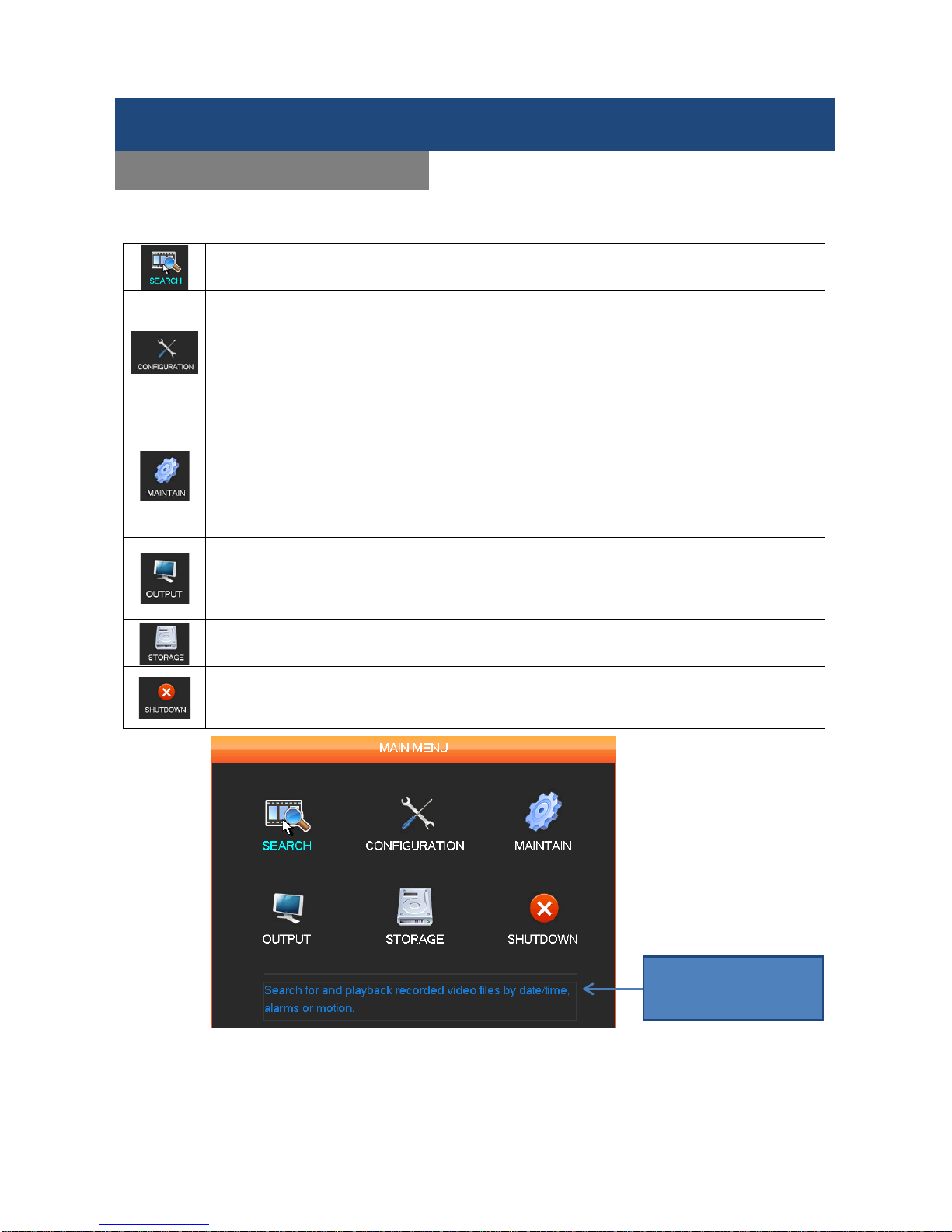
Main Menu Access
For detailed settings, there are 6 icons which represent various functions in the MAIN MENU.
Search for recorded video on system.
1. Configure Format of System Display, Languages, and Remote Control
2. Configure Image and Video Quality
3. Setup Network Information
4. Setup Motion Detection
5. User Account Management
6. Abnormalities Information Setu p
1. System Log Information
2. System Version Information
3. Restore to Default Setting
4. Stream Information
5. Set Auto Maintenance Tasks
6. Display Online Users
1. PTZ (PTZ Cameras must be connected)
2. Alarm Output (Determine which method to trigger alarms and alarm settings)
3. RS232 ( only for RS232 Interface)
4. Display Setting
1. Hard Disk Drive Management
2. Backup Management
1. Log off the Menu, and Switches Different Users
2. Shutdown the DVR
3. Restart the System
When you point at an
icon, a description of
it will appear below.
Menu Functions
Main Menu Access
Page 21
SHIELD DVR User Manual
20
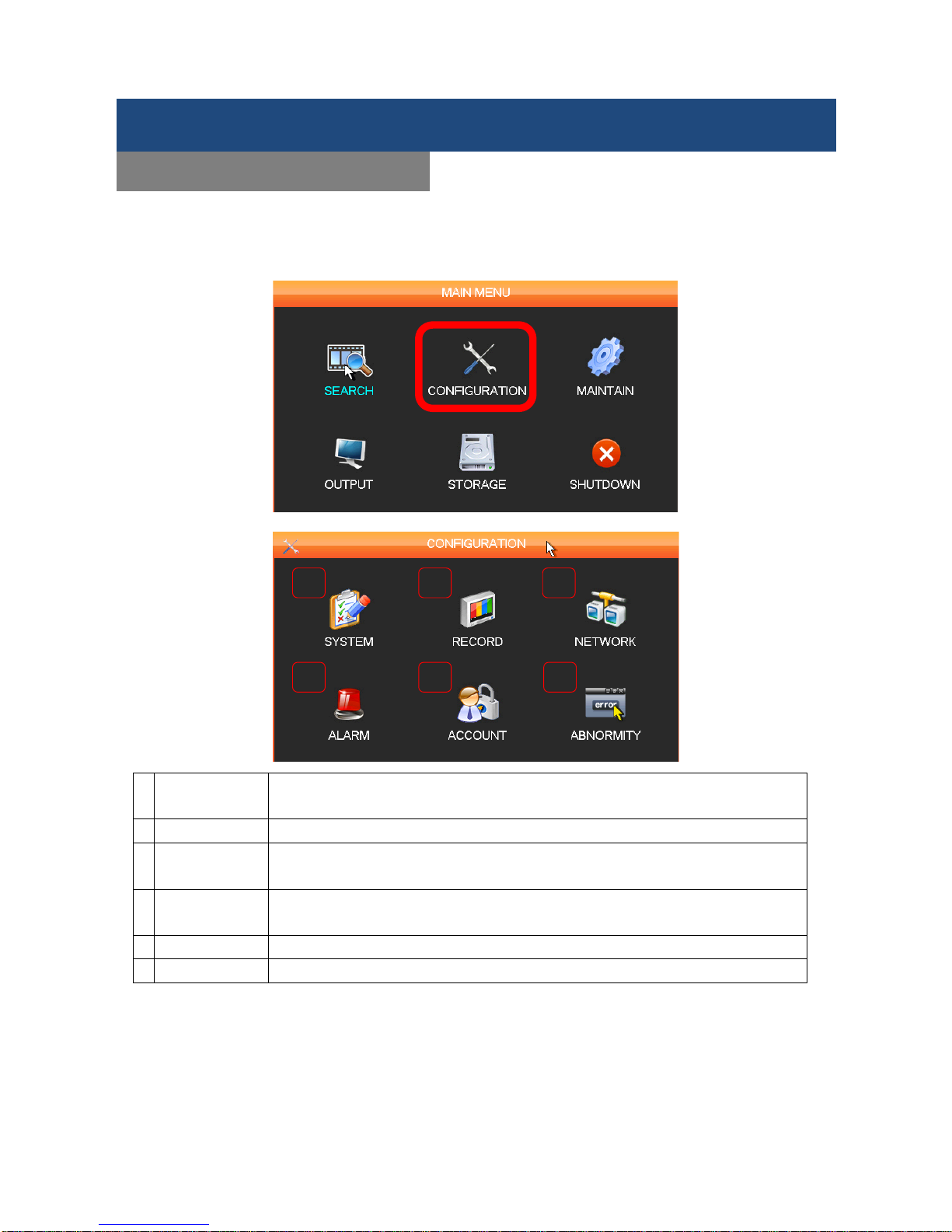
First, you can setup the basic setting of the DVR in the CONFIGURATION. You can access the
CONFIGURATION through MAIN MENU to start setting up the DVR system. You can enter the screen below,
and configure related settings.
1 SYSTEM
Configure time and display format; set record file length; language; configure
DVR remote control address
2 RECORD
Configure image quality, audio off, cover, name, and recording plan config.
3 NETWORK
Setup network paramet ers: IP address, subnet mask, default gatewa y, TCP/IP
ports
4 ALARM
Settings of exterior alarm output and responding record functions: MD(motion
detection), video loss, video cover config.
5
ACCOUNT
Users Account Management
6
ABNORMITY
Abnormal Operation including HDD error, network error and IP conflict
Menu Functions
CONFIGURATION
1 2 3
4 5 6
Page 22
SHIELD DVR User Manual
21
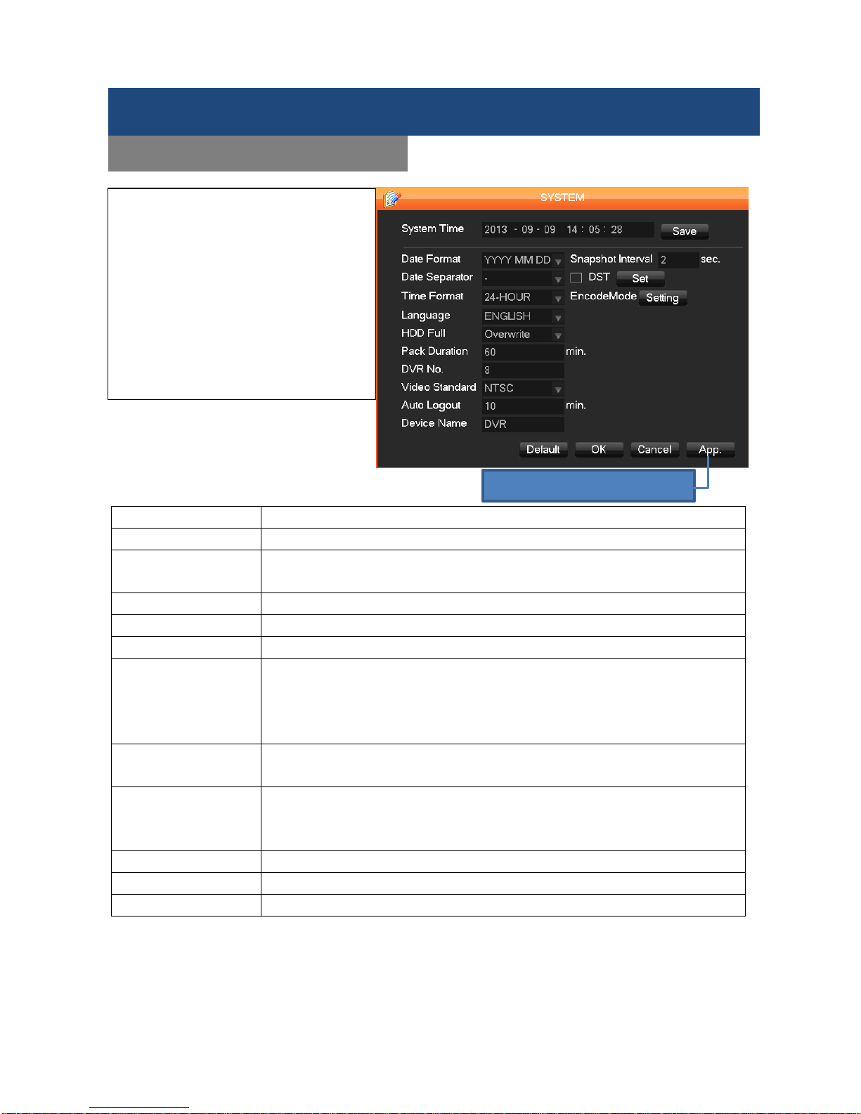
System Time
Current date and time setting.
Date Format
Modifies the date display format.
DST
(Daylight Saving Time)
Enable it, and enter local DST starting and ending dates.
Date Separator
Selects the separator for the date.
Time Format
Sets 24-hour or 12-hour display mode.
Language
Selected language varies from model to model.
HDD Full Choose “Overwrite” or “Stop recording” while the HDD is full
. If you select
“Overwrite”, the DVR will overwrite the earliest files and continue recording as if
all files are em pty. If you s elect “Stop recording” , the DVR will stop rec ording
when the hard disk is full.
Pack Duration Set length for each rec ordi ng. The default is 60 mins, the maximum is 120 mins,
and the minimum is 1 min.
DVR No. If more than one DVR is connecte d to the system , click the ADD on the remote
control and input a num ber to select the corresponding DVR to operate. This
must be done by (SHIELD Management Software in the CD.
Video Standard
Select a video standard: PAL or NTSC (must match the camera setting.)
Auto Logout
Time to logout automatically. 0 means never log -out and the longest is 60 min.
Device Name
Name of your DVR system.
Menu Functions
CONFIGURATION - SYSTEM
SYSTEM
We suggest you to set up System
Date, Time and Language and other
basic information of the DVR system
first, so that you can run the recording
in the time configuration you desire.
You can access to the SYSTEM from
CONFIGURATION menu.
Click App. to save any changes.
Page 23
SHIELD DVR User Manual
22
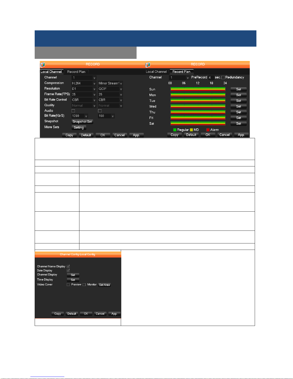
Entering RECORD via CONFIGURATION, you can setup the quality of recordings and images. Furthermore,
you can arrange your recording schedule here. Clicking Record Plan in RECORD, you can set up the
recording schedule by Regular
▇(Green)
, MD
▇(Yellow)
, Alarm
▇(Red)
modes. Clicking Set
for further
settings, you can arrange the schedule by the day and time period you want.
Channel:
Selects a camera channel you wish to schedule.
Compression:
H.264/Minor Stream1(sub-stream)
Resolution:
Choose D1 or CIF, frame rate scope is different depending on each channel and
resolution. The Minor Stream supports CIF and QCIF.
Frame Rate (FPS):
PAL: up to 25fps; NTSC: up to 30fps. (fps=Frames Per Second).
Bit Rate Control: Select CBR (Constant Bit Rate) or VBR (Variable B it Rates). If it’s set to VBR, there
are 6 levels of image qual ity. You may pick diff erent levels based on your need, and
the default is Normal.
Audio: Enable or disable concurrent audio recording for the selected video channel.
(Note: Equip with m icrophones to DVR or use cameras with a built-in m icrophone if
you want to record audio.)
Snapshot Set the singl e fr am e capture r ate. T he opt ions are 1s /pc to 8s /pc where “s /pc” m eans
number of seconds between screen snapshot and frame captures.
More Sets:
Click Setting to display the sub-menu below with additional configuration options.
Channel Name Display: Toggles on-
screen display of the
channel name.
Date Display: Toggles on-screen date display.
Channel Display: Tap Set. You can change t
he position of
camera name, and d
ifferent positions will display on the
recording and WEB interface.
Time Display: Tap Set. You can change the position of time
display, and different positions will display on the recording
and WEB interface.
Video Cover: Enable Monitor, and choose on the bo xes (most
will be 4). Cl ick Set Area to adjust the privac y zone to black
out. You can use the cursor to resize the box displayed.
Menu Functions
CONFIGURATION -RECORD
Page 24
SHIELD DVR User Manual
23
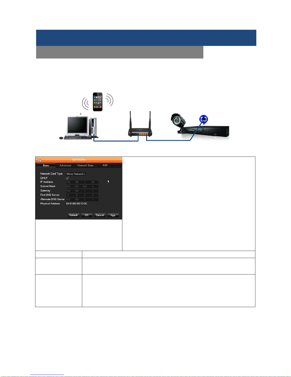
Before starting the remote surveillance, please make sure there is no problem with your internet or network
connection before connecting the DVR to the router as below. After the physical connection is done, you can
then check the LED indicator “NET” on the front panel of the DVR. When the LED is on, it means the network
connection is working.
NETWORK CONNECTION
1. Viewing via local network (LAN)
If you are only going to access the DVR via local network from
a computer sharing the same router with the DVR, you only
need to configure either DHCP or S TAT IC I P. Because all th e
devices are in the same network
, port forwarding/ port
mapping and the publ ic IP address are not necessary. Your
will just access the DVR by entering the IP address of the DVR
from the NETWORK setup into the address box of IE browser.
2. Remote Viewing outside of the local network(WAN)
Because your mobile devic e and the DV R are now in dif ferent
networks, you will ne ed to r eview and s et up Por t Forwardi ng/
Port Mapping of routers and the DDNS.
After you finish the settings by DHCP, STATIC IP or DDNS, see
the Remote surveillance in P44 for further instructions.
Network Card Type:
Display a built-in Wired Network (LAN) card.
DHCP:
Check the DHCP box to enable finding IP addres s autom aticall y. If you would like to
manually assign the netwo rk information to your DVR, uncheck the DHCP box and
entering the related network fields of your network.
IP Address:
If you don’t enable t he DH CP, you will th en d o a ST ATIC IP setting. You will need to
manually assign an IP address, enter numbers to modif y the IP Address field, and
then set the Subnet Mask and Gateway for the IP Ad dr es s. First DNS Server: DNS
server IP address. Alternate DNS Server: DNS alternate IP address. (These settings
different within every network. If you are unsure of these settings, please enable
DHCP.)
Menu Functions
CONFIGURATION –NETWORK (BASIC SETTINGS)
Page 25
SHIELD DVR User Manual
24
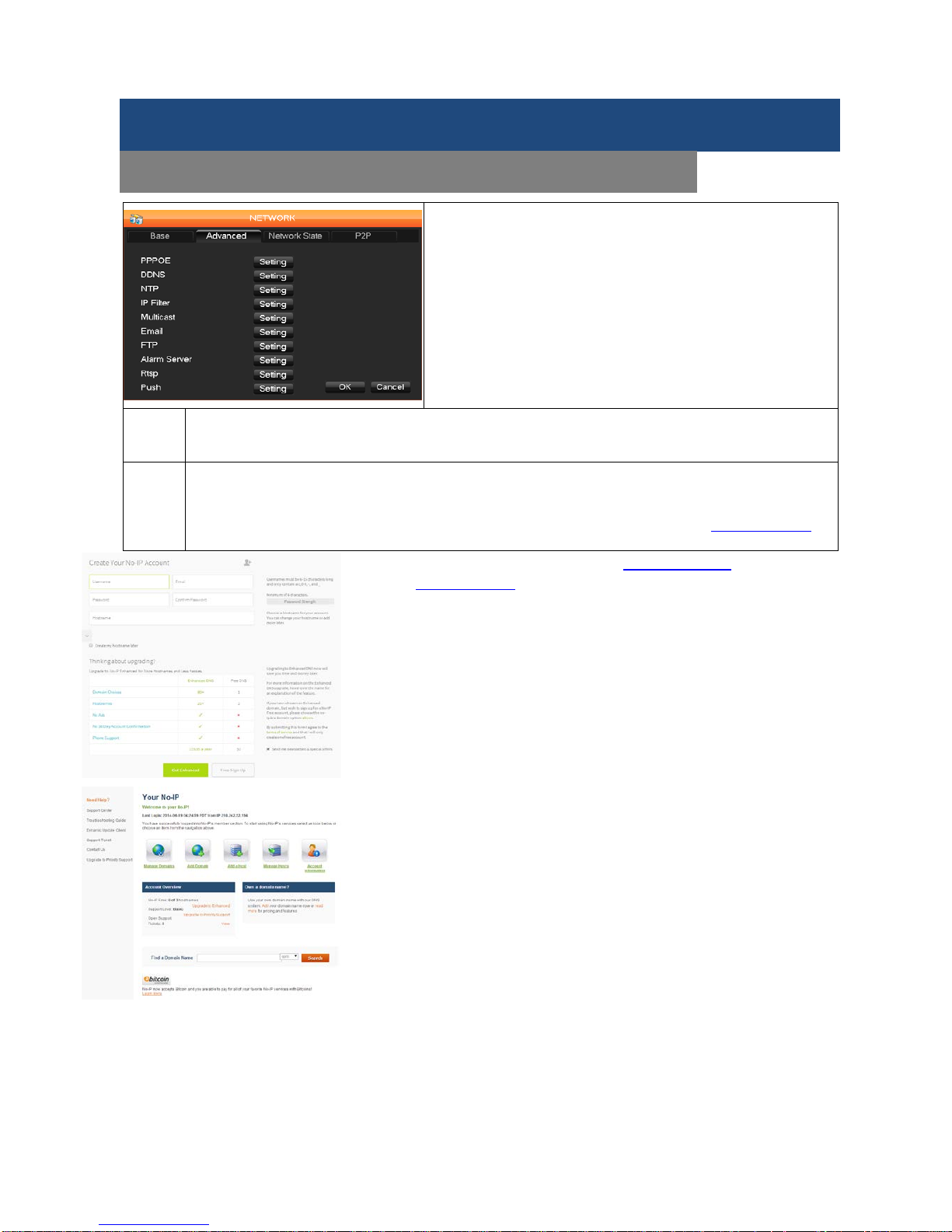
Besides DHCP and Static IP, you can still set up other
protocols for your DVR. T he below inform ation will guide you
through further settings.
For viewing access when you are outside your local network
where the DVR is setup,
please set up the DDNS and
complete the Port Forwarding/Port Mapping of your router.
Once complete, you can externally monitor via your mobile
devices.
PPPOE
This is only required if you are using a DSL connection and have the DSL modem connected
directly to the DVR. Enter the Username and Password provided by your ISP and enable it. You
can access the DVR via the web interface by typing the IP address into address bar of the browser.
DDNS
If you don’t own a static IP address, and want to view from outside of your lo cal network, we
suggest you to use DDNS service. A DDNS account all ows you to set up a web s ite address that
points back to your Local Net work so you can access the DVR over the Internet by a static or
dynamic IP address. While there are many free DDNS services, we recommend
www.no-ip.com as
the DVR has been already configured to accept account information from this service.
How to obtain your Domain Name from www.no-ip.com
1. Search www.no-ip.com via your browser
2. Decide if you only need one domain name which is free or require
multiple names for a fee.
3. Follow the instructions for completing the required information to register
4. You will get a confirmation mail with your new domain name. Ex: domain
name might be xxx@no-ip.com. You will need it to configure the DVR.
1. Obtain your Router DNS
You need to get your DNS manually from your router. You will need the
Primary or Secondary DNS from your router for DDNS to continue.
To obtain your Primary or Secondary DNS:
1. Log into your rout er usin g its Default Gatewa y addres s. NOT E: Ref er to
your router`s manual or software for login information.
2. View its WAN settings. Write down the Primary or Secondary DNS
address for use in the next step.
2. Configure DDNS settings in the DVR
In the Network>Base, enter Primary or Secondary DNS as the WAN
settings of your router in the DNS field
1. Click Network>DDNS
2. Select DDNS Type, Enter the Domain Name, Use r Name, Password
you received from the confirmation email of DDNS service. For example:
if your domain name is adam@no-ip.com, you need to enter adam@
no-ip.com, in the text field via the Virtual Ke yboar d.
3. Click APP then OK.
Menu Functions
CONFIGURATION –NETWORK (ADVANCED/DDNS)
Page 26

SHIELD DVR User Manual
25
Port Forwarding/Port Mapping/Port Triggering
Port Forwarding allows com puters and devices outside of your network to communicate with computers
and devices within your local network . You will need to forward ports 80 from the attached router to the IP
address of the DVR. You will need to know the user name and password for your router. There are 3 Steps to
follow:
Step 1: What’s the IP Address of the DVR
NOTE: The DVR and PC must be connected to the same router and be powered up before proceeding.
1. Enable DHCP in the NETWORK setup. Check the IP Address in the box and write it down.
Step 2: Configure your Router for Port Forwarding
Please refer to the procedure of Port Forwarding below.
NOTE: Although all rout ers are diff erent, the following is the basic inform ation that needs to be configured.
Consult your Router Manu al for details on Port For warding for your router or c ontact the manufacturer for
assistance. Some Internet Service Providers ( ISP) may block access to these settings provided by router.
You may contact your ISP to change it f or you.
1. Access your router’
s Port Forwarding
screen (See image at left). Your router may
be slightly different but the information
required is the same.
2. Choose Add custom Service
3. Enter your port forwarding information for
each port you want to forward. Y
ou will
need to forward ports 80. And e
nter your
DVR IP address you obtained from Step 1.
4. Click Apply, and it’s finished.
Input the IP address into t he web brows er, a nd
add the port# of DVR you want after IP. ex:
http://192.168.1.109:81. If you want to access it
via SHIELD management software (in CD), yo u
can use the outer network TCP port directly.
Port Forwarding Naming Tip
For clarity and easier ident if ication of port s in your r outer we sug gest nam ing th e ports as follo ws: Port 80 is
for your W eb Browser - name this port “DVR-Web”. Port 900 0 is for streaming media - name this port
“
DVR-Media”. Port 100 is for your mobile phone - name this port “DVR-Mobile”.
NTP
Turns NTP on/off. It allows the DVR to automatically sync with an SNTP time server.
IP Filter DVR authority management. If you enable the white list, only IPs in the list are allowed to
connect. This system supports a maximum of 64 IP addresses.
Multicast Sets transfer capability and ports. Note: The settings for Multicast are advanced technical
settings. Don’t change them unless you know what you’re doing.
Email Set the sender mailbox SMTP server IP address, port, username, password and mail SSL
Encryption. Emails support Chi nese, English and Arabic num erals. Maximum: 32 c haracters.
Max supports: 3 Receiving Addresses and SSL Encryption Mailbox.
Menu Functions
CONFIGURATION –NETWORK (Port Forwarding)
Page 27

SHIELD DVR User Manual
26
NTP function
The NTP function handles time synchronization
between the DVR and the GPS clock server to
ensure the accuracy of both devices.
Internet Configuration
CONFIGURATION → NETWORK
, select
Advanced → NTP
to configure it. The NTP function can use a
standard NTP server to automatically set the time. Enter the IP address and domain name of an NTP server.
To activate the NTP function, click “Enable”.
You can select how often the time of DVR will update. The interval options are from 1 to 65,535 minutes.
Intranet Configuration
If the DVR is connected to an intranet, the user can use a privately-owned server as the clock source. Enter
the private NTP server address in the DVR’s NTP configuration (as noted above) to set it as the clock
source.
Privately-owned NTP servers can use standard NTP products to provide accurate time setting from a PC
system. Please refer to the instructions below when using a PC system as an NTP server.
NTP Server Set Up under Windows
Start
→
Run
, input
regedit
to enter the registry editing feature.
Build a new key assignment of DWORD Value by going to:
HKEY_LOCAL_MACHINE\SYSTEM\CurrentControlSet\Services\W32Time\Parameters\registry sub key
(NtpServer);
Change the value to 1, and save.
Restart the computer.
NOTE: Changes to Windows registry must be done carefully and only make the changes as noted above. It
is the best to always make a backup of your registry before attempting any changes.
NTP Server Set Up Under Linux
Due to the differences between Linux distributions, for details on how to set up an NTP server under Linux,
refer to the manual for the distribution you are using.
Menu Functions
CONFIGURATION –NETWORK (NTP)
Page 28

SHIELD DVR User Manual
27
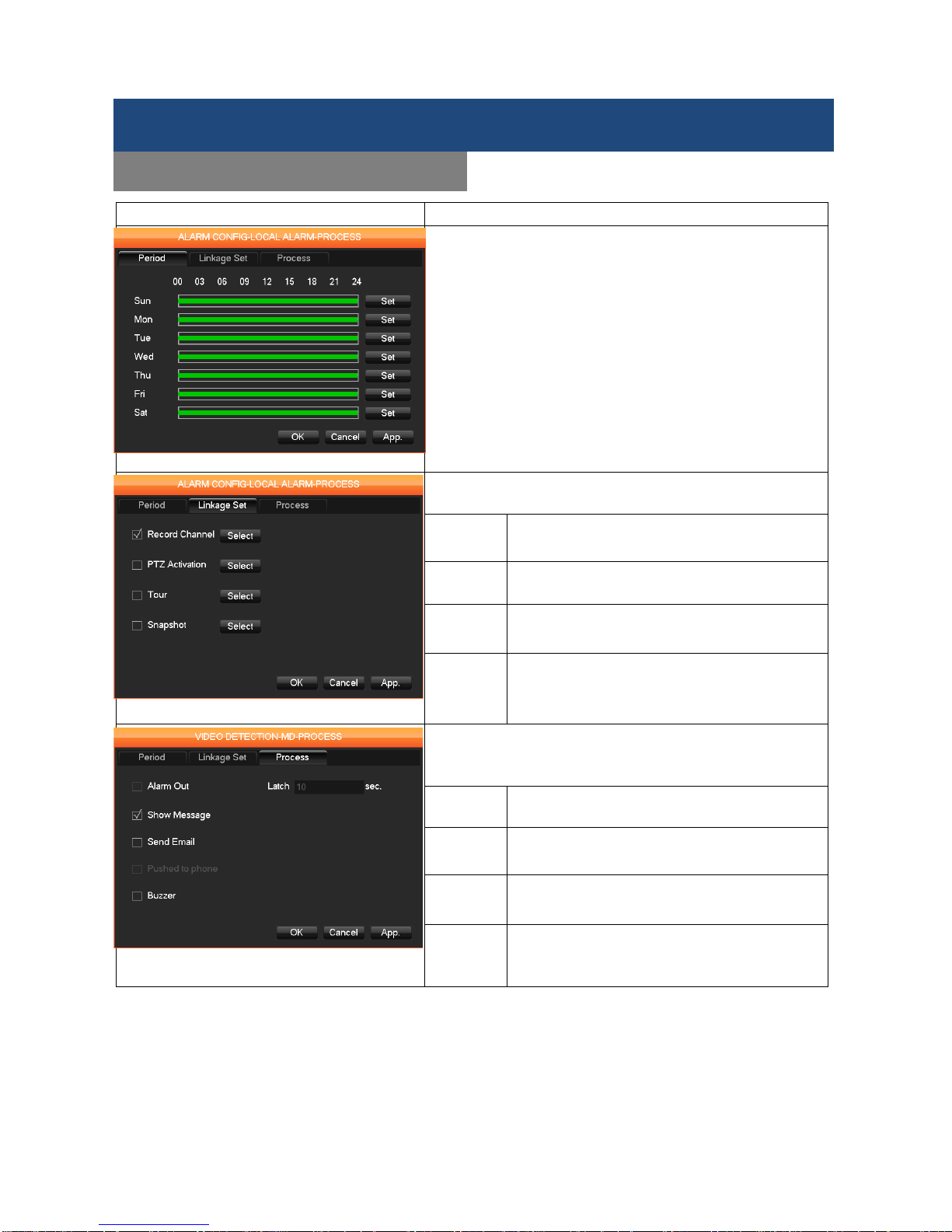
Detect Tab Settings
After entering the ALARM, we suggest you to setup Detect first to setup the basic operation of Motion
Detect(MD), Video Loss, and Camera Masking. This will help you to setup Local Alarm and Net Alarm
settings.
1 Motion Detection: Motion detection and alarm . You can set the areas that alarms are sent while
motion is detected and schedule the date and time that you want to apply in
Motion Detect Mode. Furthermore, you can setup the sensitivity and Trigger
interval in this mode.
2
Set Area: PAL: 22*18 = 396, NTSC: 22*15 = 330 zone mask.
3
Sensitivity: There are 6 sensitivity levels.
4 Video Loss: Detects video feed loss and alarm setting. While the Video is lost while recording,
the alarm will be sent to notify users for this issue. You may also click Process to
schedule it.
5 Camera Masking: Camera mask and a larm set. While the camera view is blocked, the DVR s ystem
will deliver the notification to the user to provide full security for your safety.
6 Preferences Start: Alarm preview. Click to demonstrate the alarm immediately to check if your
settings are OK.
7 Process: Entering the alarm configuration interface to setup the Alarm Period, Linkage Set,
and Process. You may refer to the next page for further settings for this function.
Note: RSCM-0704B041, RSCM-0708B041, RSCM-0708B081 (4-channel and 8-chann el DVRs ) have no
LOC AL ALARM so this tab is not functional.
Menu Functions
CONFIGURATION -ALARM
1
2 3 4 5 7
6
Page 29
SHIELD DVR User Manual
28
Function Description
Period
Set the period to trigger the alarm. Click Set and select up to
6 different periods th at th e alar m is activated (check the box
and then select periods the alarm should be activated –
selecting
00:00 to 24:00 will set the alarm to run
continuously)
Linkage Set
Activate which monitori ng method will be used, and setup
for advanced PTZ Cameras.
Record
Channel
Continuous recording with all
channels with
time delay that is set.
PTZ Record with a PTZ camera (recording m odes
are: none, preset, tour and pattern.)
Tour Continuous recording using the “tour” method
(recording from one camera to another).
Snapshot Recording with a sing le frame (picture) instead
of continuous recording.
Process
Enable or disable how to setup an alarm, show the message
in the screen, sending emails to user list or the buzzer
setting.
Alarm
Out
4/8 channel DVR kits are not supported
Show
Message
A
message on the viewing monitor that an
alarm has been activated.
Send
Email
Send an email alert all members listed th at an
alarm has been activated.
Buzzer A buzzer to tell the alarm is activated. Time
delay for alarm cancellation is 10~300
seconds.
Menu Functions
CONFIGURATION -ACCOUNT
Page 30

SHIELD DVR User Manual
29
The default users are admin, user and default. The password of admin and user is 123456. The admin has
all authority to the system while user can only process surveillance and playback. The default doesn’t need
the password to log in and can’t be deleted. Systems automatically log in with default if there is no user
logging in. A user can change some settings then some configuration can be performed without logging in.
1 Add User Add group member information and set authorizations. Here to enter a User name,
password and selec t the Group and Reusable. Reusable
□
allows the account to be
used for multiple logins.
*NOTE* Users can only belong to one Group and right of users cannot exceed Group rights.
2 Modify User Modifies existing group member information and authorizations.
3 Add Group Adds groups and sets up group authorizations.
4 Modify group Modifies existing Group information.
5 Modify
Password
To change a password, select a User name and enter the old password then a new
password. Click OK to confirm and finish setting.
A password must be 1-6 characters length and can use char acters including letters,
numbers, and limited s ymbols (underline, d ash and dot). You c an’t use a space as a
beginning or the las t character. An y account with managem ent (admin) authoriz ation
can change the passwords of other accounts.
Menu Functions
CONFIGURATION -ACCOUNT
Page 31

SHIELD DVR User Manual
30
Here to setup the inform ation when abnorm al settings are m ade to prevent s ystem error dur ing the setup or
operation of DVR system. To activate a war n ing or er r or message in advance w hi le system runs wrong, click
on the check box in front of each option. The button next to each option gives access for
further settings.
No Disk
Alarm when the internal HDD can’t be detected. (The default is enabled.)
Tap Process for Alarm Output, Show Message and Send Email settings.
No Disk Space
Alarm when hard disk capacity is lower than the percentage threshold you enter. Tap
Process to access further settings .
Net
Disconnection
Alarm when a network is not connected. (The default is enabled.)
Tap Process to access Alarm Output, Show Message, Send Email, and Record
Channel.
IP Conflict
ed
Display a warning when IP addresses are conflicted. (The default is enabled.)
Tap Process to access further settings.
Disk Error
Display a warning when there is an error in reading or writing to the hard disk.
Tap Process to access further settings.
Menu Functions
CONFIGURATION -ABNORMITY
Page 32
SHIELD DVR User Manual
31
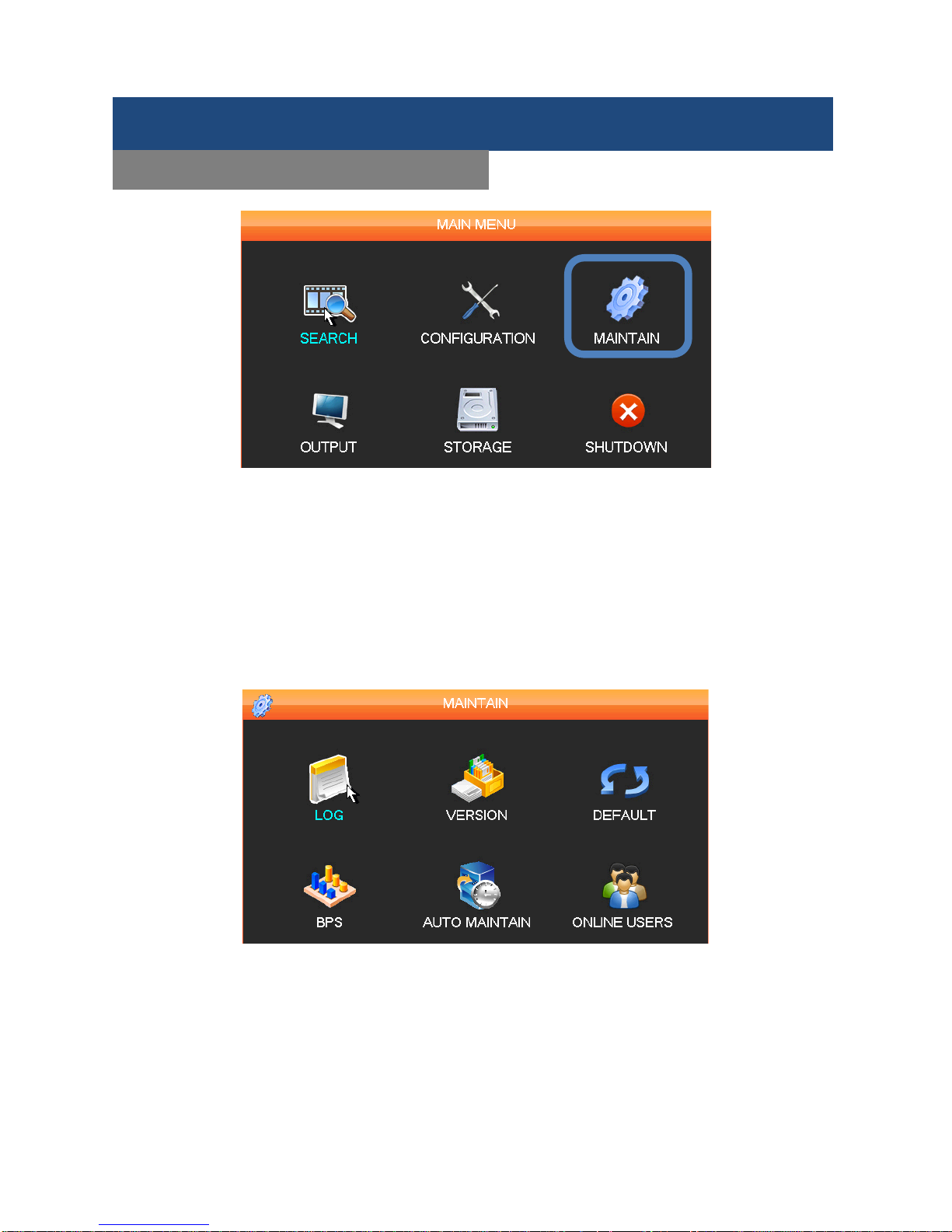
Here users can check out the information about the DVR system including the basic hardware information
and system software details. If update or the defaults of the system are needed, users can process in
Maintain Menu. Users can access MAINTAIN through MAIN MENU, and you can enter the screen below,
and configure relative settings which is including LOG, VERSION, DEFAULT, BPS, AUTO MAINTAIN, and
ONLINE USERS.
Menu Functions
MAINTAIN
Page 33
SHIELD DVR User Manual
32
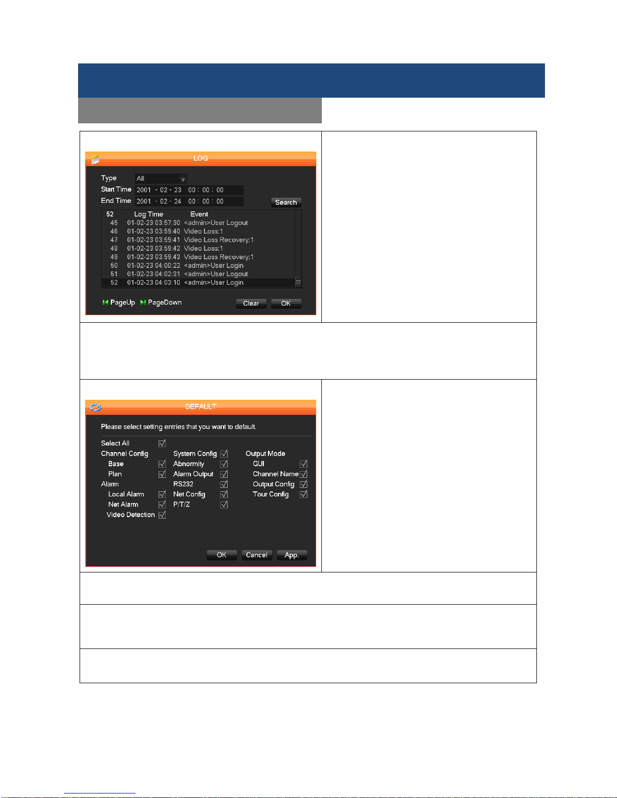
LOG
Here to display all log information of the DVR
system.
Select the Type and the time segment you want
then click Search. The system will display the
log in tab form.
Type: System, Configuration, Storage; Alarm
event; Recording; Account management; Clear
the log, Playback operation, or all for what you
want. Select the type and time segment and
search to filter the log list. Or click Clear to delete
all logs.
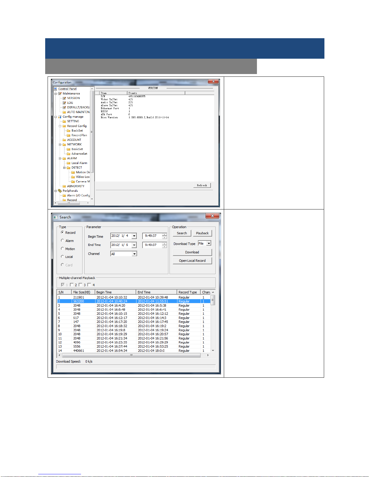
VERSION
Display features, software version and some other information of the DVR system.
Start: You can also upgrade th e DVR’s firmware by connecting a US B flash drive whic h contains the
upgrade firmware and click Start.
DEFAULT
The Defaults menu restores system defaults.
You can restore the defaults selectively by
selecting only those items you require O
r you
can restore all defaults by selecting all items.
Restore the DVR system to default setting or
select the items you want as default setting.
BPS
Displays the video size and data rate of each channel by waveform.
AUTO MAINTAIN
Sets up auto maintenance items: auto-reboot will automatically reboot the DVR at days and times specified
(reset all cameras) and auto-deletion of old files will delete files that reach the time limitation that is preset.
ONLINE USERS
Displays which Users are currently online accessing the system.
Menu Functions
MAINTAIN
Page 34
SHIELD DVR User Manual
33
Index
Type
Description
1
Calendar Click a specific date for your recording.
2
Time
Check Recording List to select recording search start and end time.
3
Play Stop/Play, Pause, Forward, Backward, Previous/Next Frame in pause mode.
4
Recording
mode
Choose searched recording mode, including NORMAL, ALARM & MOTION.
5
Channel
Choose the channel you want to view
6
Play
Choose to play the previous or next file; the previous or next channel.
7
List
Choose the start time, channel, click search, and a list will display the results.
8 Backup
Click to choose a backup file in the file list box, click the Backup button; to
cancel a backup file, click √ from the backup menu √.
9
Search
List
The search list displays up to 128 video recordings. Choose a file and press enter or
double-click with the mouse to view a recording. File types: R—normal recording,
A—alarm recording; M—motion detection recording.
10
24HR
After the date is selected, you may start the video by clicking on the time bar.
Menu Functions
MAIN MENU: SEARCH
1
5
7
2
9 8 4
3 6 10
Page 35
SHIELD DVR User Manual
34
View recorded video on the system through the SEARCH Menu. To search for the videos:
1. There are two ways to access the SEARCH menu, Right click anywhere on the screen and select Search
from quick access menu, the SEARCH menu opens. Or from the Main Menu select SEARCH.
2. Click Play to playback the last minute of recorded video or choose a specific date and channel from
and to search the recorded video and click on the time bar , and start to play the recorded
video.
(Note: You can only key in the date by virtual keyboard (mouse only).
Playback Control:
Key Description Remark
Fast-Forward
During playback, pressing allows you to
Fast-Forward with higher speed to choose the
video. It can also be used as a reverse of the
Slow Motion key.
Actual play rate is based on the
speed being used.
Slow Motion │
During playback, pressing │ for slower
playback speed. It can also be used as a
reverse of Fast-Forward.
Play/pause►/
Play/Pause can also switch to normal speed
from slow motion playback.
Backward
Backward the recorded videos
Click again to start backward.
Press rewind or single-frame
advance to store the backward
videos.
Press the play button ►/ to
resume normal playback.
Manual single frame
advance
Advance video by a single frame forward or
back by clicking either │ or when video
is paused.
Note:
1. The DVR playback control bar shows playback speed, channel, time, progress and others.
2. The playback speed and rewind functions can differ between DVR versions. Please check the DVR version
you have in order to ensure successful operation.
Menu Functions
SEARCH
1
5
10
Page 36
SHIELD DVR User Manual
35
Users are able to set up different devices connected
to the
DVR system here, and m odify the display settin gs depending
on one’s preference.
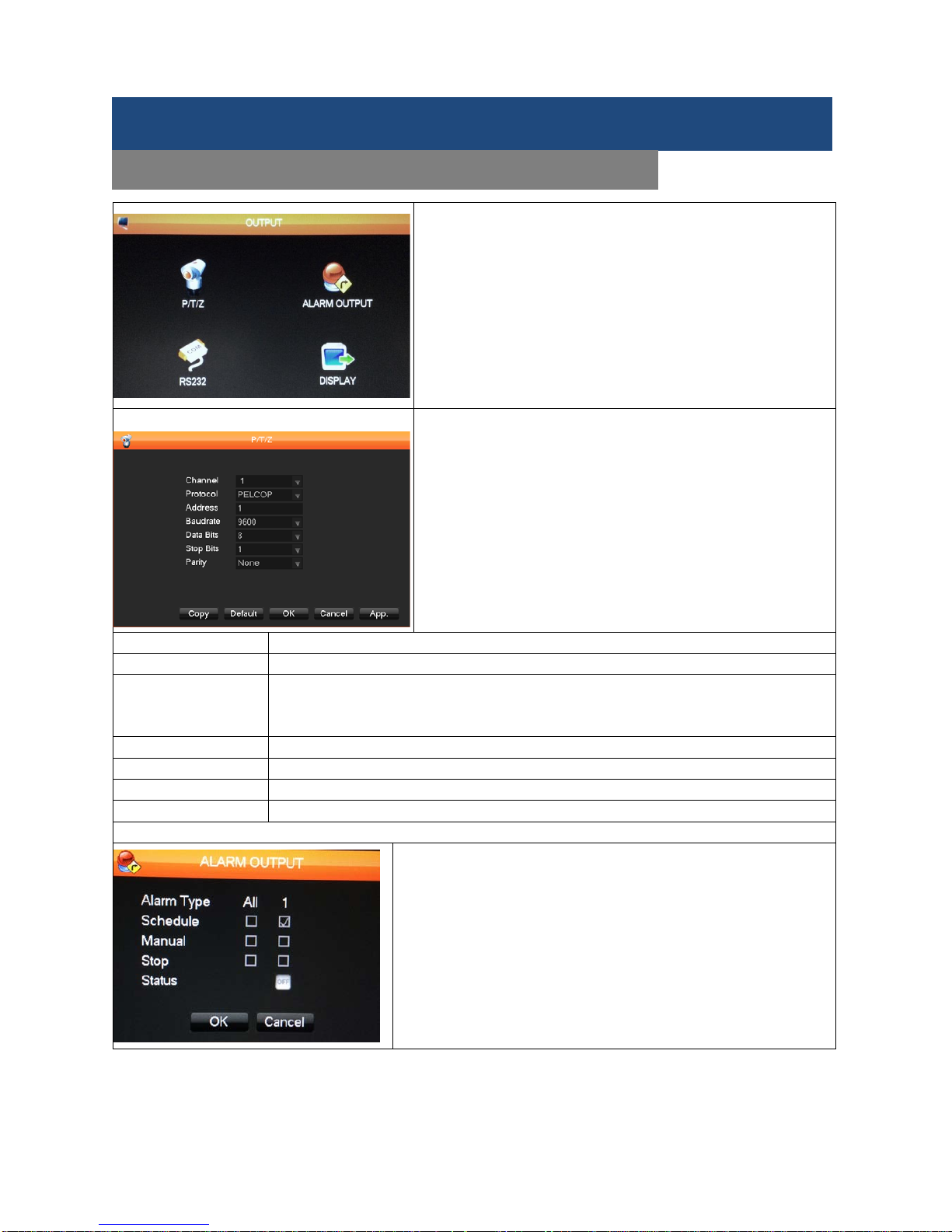
The Output menu contains 4 functions, P/T/Z, RS-232, Alarm
Output and Display which control the management of the
peripherals connected to the DVR system.
P/T/Z CONFIGURATION
(A supported PTZ capable camera must be installed to use this
feature)
Set the Pan/Tilt/Zoom channel, protocol, address, baud rate,
and others for a P/T/Z camera.
First, set the cam era address and ensure that the R S-485 A
and B cables between the c am era and the DVR are connected
correctly. See the configuration interface below.
Channel
Selects the P/T/Z camera channel.
Protocol
Selects the associated camera protocol (e.g. PELCOP9).
Address Selects the associated camera address. The default is: 1.
Note: This address has to be corresponded with the camera address, or the cam er as
will not work.
Baud Rate
Selects the camera’s baud rate and control, the default is 9600.
Data Bits
Default: 8
Stop Bits
Default: 1
Parity
default: None
ALARM OUTPUT
Choose types of alarm you like to setup and click OK to save it:
Schedule: Alarm your DVR by schedule
Manual: Force to start alarm right away
Stop: Stop the alarm
Menu Functions
OUTPUT
Page 37
SHIELD DVR User Manual
36
RS-232
Note: For som e model without RS232, you don’t
need to set up.
Function
Console: Upgrade and adjust by port and software;
KeyBoard: Keyboard connected by port
NetKeyBoard: Keyboard connected by net port;
P/T/Z matrix: Controls the PTZ matrix.
Baud Rate
Selects the camera’s baud rate and control, the default is 9600.
Data Bits
Default: 8
Stop Bits
Default: 1
Parity
default: None
Display
Display menu sets the unit's display and polling features. The menu has three tabs, GUI, Output
Configuration and Tour Configuration.
Display: Display menu shows t he unit's display
and polling features. The menu has three tabs,
GUI, Output Configuration and Tour
Configuration.
Menu Functions
OUTPUT
Page 38
SHIELD DVR User Manual
37
The GUI sets the appearance of the Screen Display.
Transparency: 4 levels from Transparent to Opaque.
Channel Name: Modify the name you want. The
available options are symbols, letters, and numbers.
Names can be up to 48 half-width characters and
limited to 16 characters, otherwise some problems may
occur in multi-screen mode.
Time Display: check If time is displayed on scr een or
not.
Channel Display: Select if
the channel name is
displayed on screen or not.
Overlay Info: Select whe ther overlaying infor mation is
displayed on screen or not.
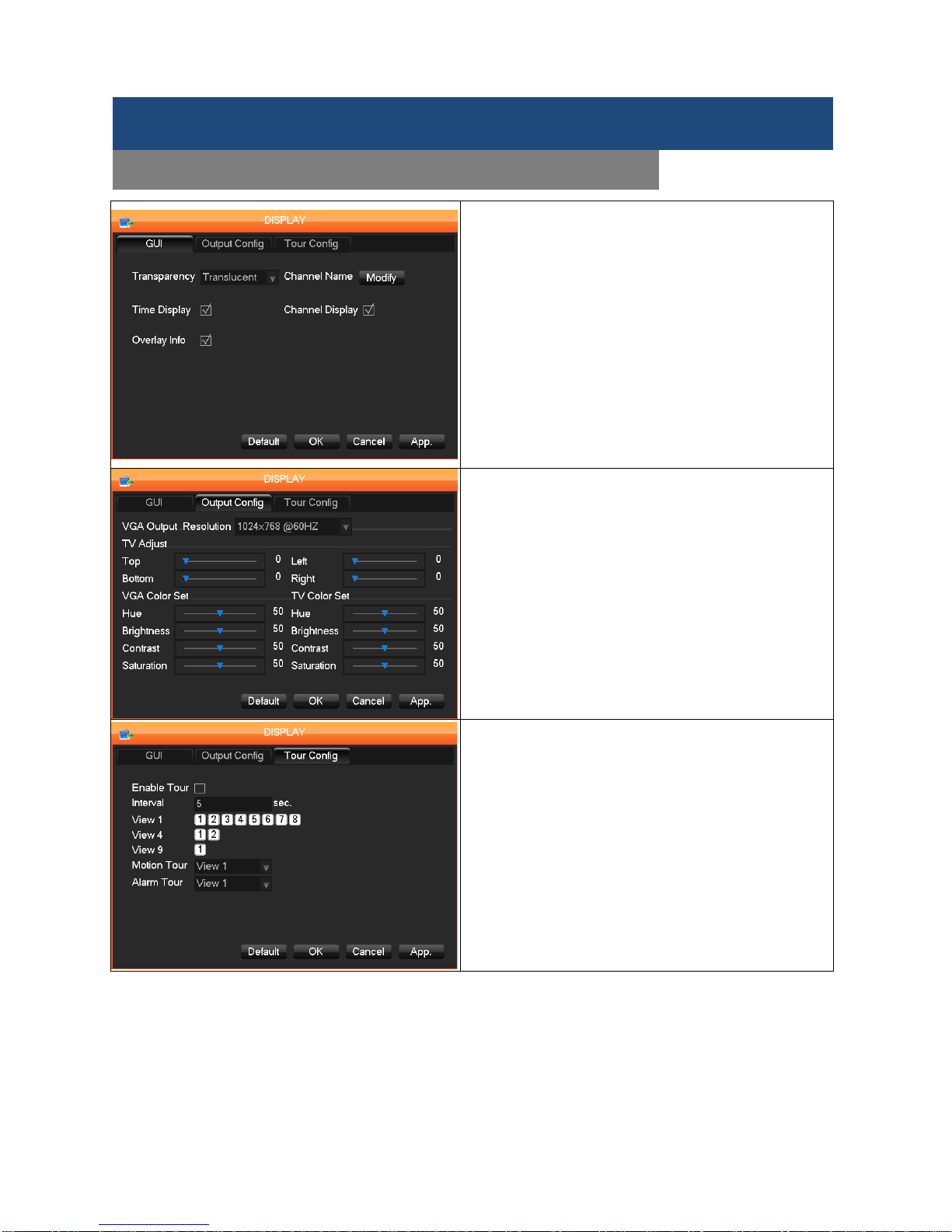
The Output Configuration displays several control
settings for a video display monitor connected to the
DVR system.
VGA Output Resolution: Select VGA resolution and
refresh rate, the defau lt setting is 1024 × 76 8 @60Hz.
There are several options to take.
TV Adjust: Adjust the display output area. It adjusts the
image to the fit the display.
VGA/TV Color Settings
: Adjust the display’s hue,
brightness, contrasts and saturation settings.
The Tour Configuration tab sets up and enables the
touring functions
This menu sets up the tour mode and intervals between
rotations of the camera channels. The time interval
option is 5 to 120 seconds and includes mode for
single, four, or eight screen options.
Motion Tour: Set up motion detection tour mode.
Alarm Tour: Sets up the alarm-based tour mode.
Note: Setup shortcut; Click the button at the upper
right-hand corner of the monitored display, or press the
Shift Key, switch modes and allow you to control the
tour.
Menu Functions
MAIN MENU: OUTPUT
Page 39
SHIELD DVR User Manual
38
The HDD Manage m enu has two functions, HDD Base and HDD
Record which give access to disk management.
HDD Base shows DVR storage capacity, available space and
operational status.
Format: Enables User to format the DVR’s internal hard disk.
Set: Tap on t he hard disk you want, and click Set to contr ol the
access mode setting. The options are read-write, read only or
redundant. Check the box to enable or disable each mode. In
Read Only mode, video data cannot be recovered. The sub-menu
also displays a variety of drive status information. HDD S.M.A.R.T.
Technology
HDD Record menu displays a recording log with recording start
and stop times.
Menu Functions
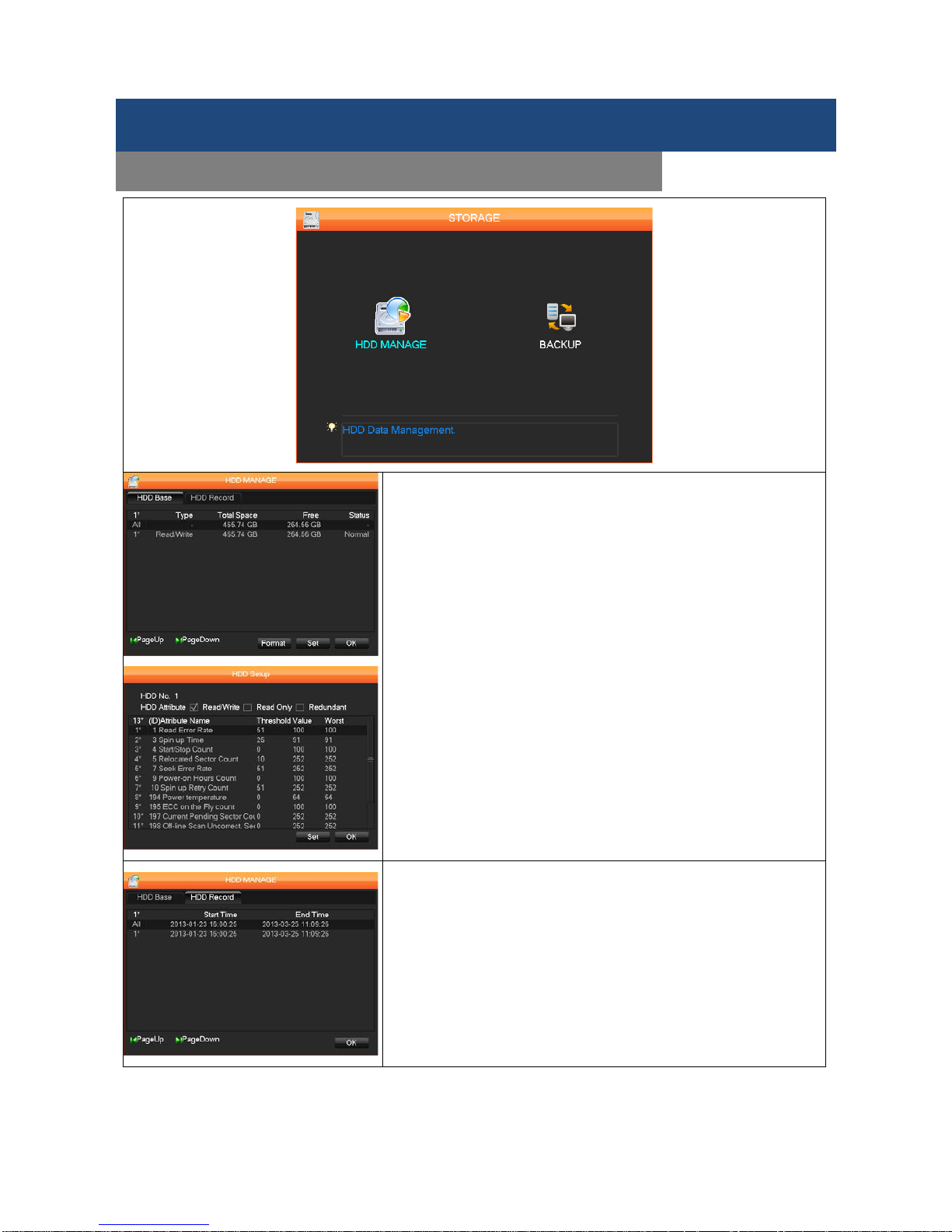
STORAGE – HDD MANAGE
Page 40
SHIELD DVR User Manual
39
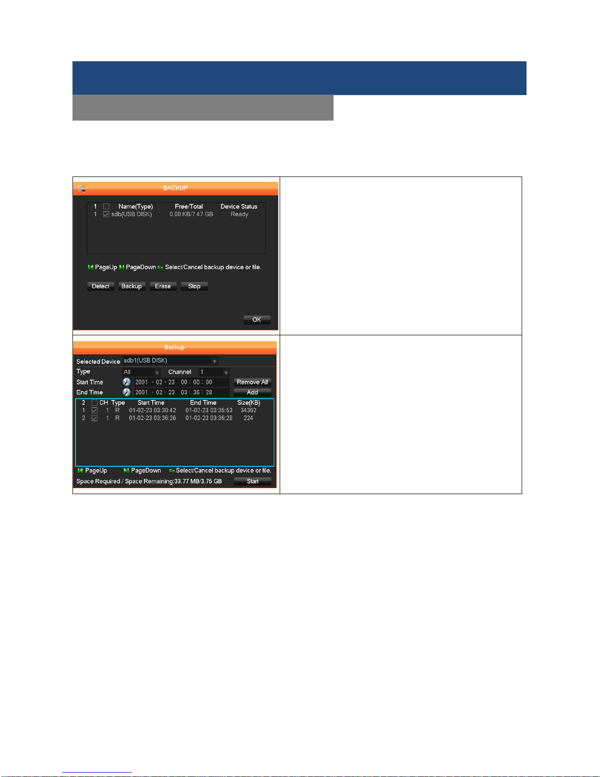
This DVR system supports data backup by USB flash, DVD writer and USB HDD. Connect an external USB
device to one of the USB ports to back up video recordings from the DVR’s internal hard disk.
Connect an external USB device to one of the USB ports
to back up recordings f rom the DVR’s internal hard d isk
in the Backup menu.
Detect: Identifies the ex ternal USB device and d isplays
the device information.
Backup: Click on the box for the target external drive
then click Backup to enter the Bac k up m enu.
Select the recording’s St art and E nd times and click Add
to add it to the list. Duplicat e it by inpu tting the St art and
End times again. Click Remove All to clear the f ile list.
Select the recording you want and click Start to backup,
and display the time remaining.
Erase: Deletes all data on USB backup device.
Note: USB backup automatically controls the DVR
storage location.
Note: Erase will cause permane
nt data loss by
overwriting the target device and any data on it.
Menu Functions
STORAGE - BACKUP
Page 41
SHIELD DVR User Manual
40
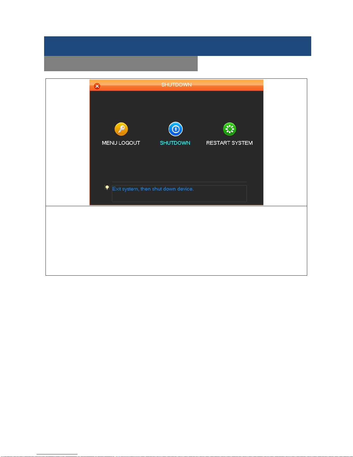
MENU LOGOUT
SHUTDOWN
RESTART SYSTEM
Note: Turn DVR power off using the power switch if you plan to exchange the internal hard disk.
Menu Functions
SHUTDOWN
Page 42

SHIELD DVR User Manual
41
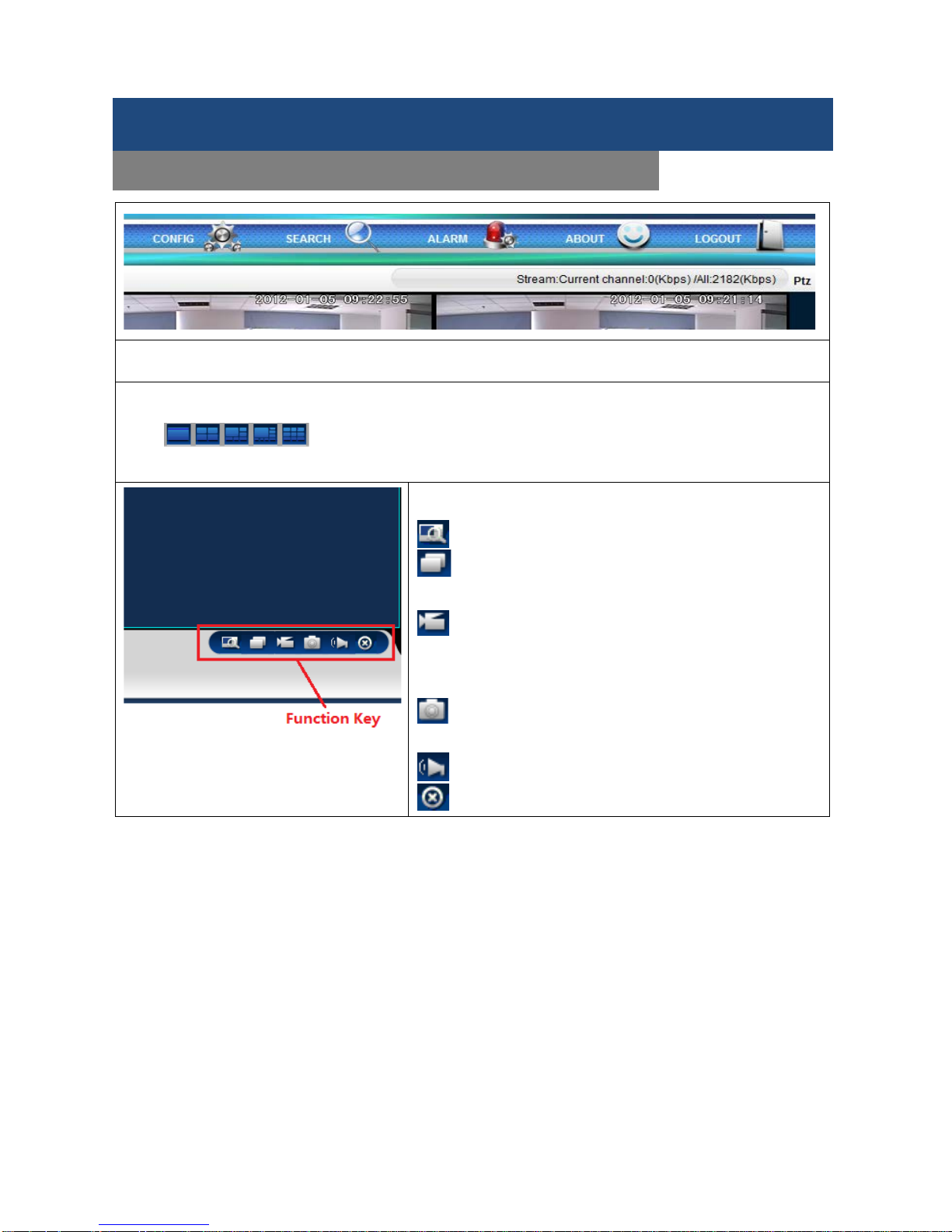
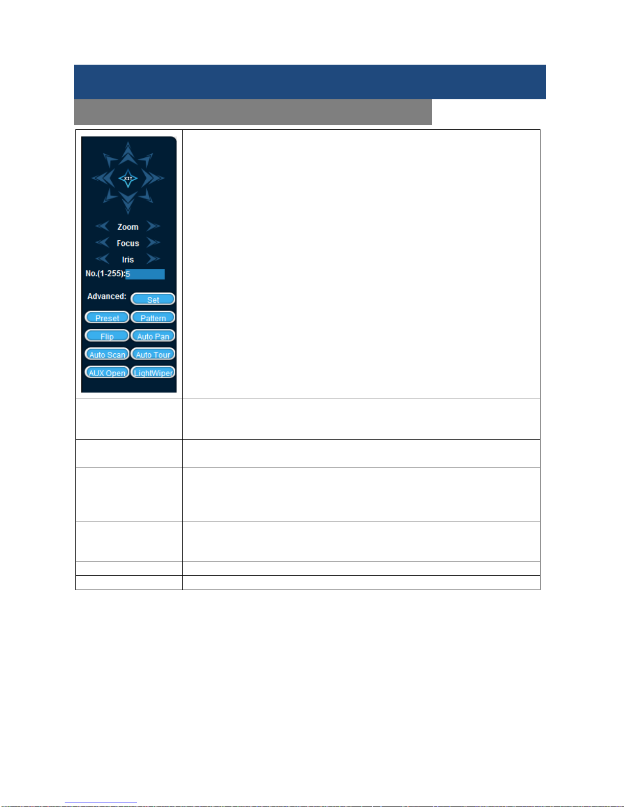
In the Live Screen, right click and select P/T/Z Control on the control channel. From P/T/Z control, you can
set direction step length, zoom, focus, iris, advanced features, auxiliary features, and camera settings.
Step size
Controls P/T/Z directio n and speed, e.g. step size 8 is faster than s tep
size 1. (Range 1-8, 8 is the maximum)
Zoom, Focus, and Iris
Click and for zoom, focus and iris modification.
Direction Control There are eight directional controls: up, down, right, left, upper left,
upper right, lower left, lower right. ( The front panel control only uses 4
directions).
Quick location:
<SIT>
Use the <SIT> button in the m iddle of the d irec ti ona l ar r ows; make sure
the protocol supports this function and use only m ouse control. Click
any point and the P/T/Z camera will turn to it and move it to the center of
the screen. Drag the mouse to find the l ocat ion p age, it supports 4 ~ 1 6
times variations, dra g f r om top left to bottom r ight t o zoom in, drag from
bottom right to top left for zoom out.
Page Switch
Switch to the advanced functions
Preset: Enter the desired previousl y configured Preset number in the
number field then click the Preset button to select it.
Tour: Enter a Tour number in the number f ield and click on the “Tour”
button to run it or stop a tour using the “Stop” button.
Pattern: Enter a Pattern num ber and click on Pattern button to run it.
The camera will follow the set patrol path. Right click to hide the menu.
Click the directional key in menu to stop the patrol.
Auto Scan: Click line for the line scan f unction as per set line to sc an,
the button will turn into Stop, if you want to stop the motion, click it.
Advanced Settings
PTZ Setup and Control
Page 43

SHIELD DVR User Manual
42
P/T/Z SETTINGS
AUX
Click Page Switch to enter the AUX interface. (Corresponding with
protocol)
Click Set to set Preset, Tour, Pattern and Border
. Grayed out keys
represent unsupported functions.
Preset: Set up camera positions by the directional keys.
Click Preset and input a Preset number then click Set
to save the
coordinates to that Preset number.
Tour: Select Tour. Input numbers into Preset and Patrol No.
Click Add Preset to a dd a preset i n the cruis e path, r epeat to add more
presets.
Click on Delete Preset】 to delete a preset, repeat to d
elete more
(clearing presets cannot be supported by some protocols).
Pattern: click the Pattern box to record the proc ess as Pattern “X” (a
number),
Begin: click Begin, go back to the P/T/Z control menu to modify the
Zoom, Focus and Iris settings; then go back to the menu below End.
Border: Click Border. Move the c amera to t he left a nd rig ht boundar ies
(furthest range of motion) using the directional keys and click on Left
Border and Right Border respectively to confirm the settings.
Advanced Settings
PTZ Setup and Control
Page 44

SHIELD DVR User Manual
43
P/T/Z Camera Settings
Click Page Switch to ac cess the cam era setting in terface ( only supp orts part of the pro tocol). Enter Menu
and Exit Menu access or quit the camera settings menu.
Click Page Switch to get back to interface.
The directional key is mainly used for internal menu control, i.e. the camera menu control. Grayed out
buttons indicate an unsupported function.
Note: The Up/Down arrows change menu item selections while the Left/Right arrows change menu options.
Advanced Settings
P/T/Z Camera Setup and Control
Page 45

SHIELD DVR User Manual
44
DVR FIRMWARE UP DATE
You can update the DVR firmware using a downloaded update file available on www.rosewill.com
(1) Unzip the DVR update file (e.g. DeviceUpdate_V1.10.R.20120822.rar)
(2) Double-click the DVR network update tool (RECUpgrade.exe) as below:
(3) Enter the IP address and TCP port code of the DVR device. Click on Login and a login window will
display:
(4) Enter a User name and password and click on OK to log in to the DVR:
(5) Drag the "updatepacket.bin" file to the entry box which shows after opening the files as illustrated below:
Advanced Settings
DVR FIRMWARE UPDATE
Page 46

SHIELD DVR User Manual
45
(6). Click the BIOS button to the updating.
(7). USB UPDATE
Re-name the updatepacket.bin file to vss.bin, put it into the root directory of a USB drive, then plug the USB
drive into the USB port on the DVR. Using the DVR’s OSD interface, go to Main Menu > Maintenance >
Version and click on Start to install the update.
Advanced Settings
DVR FIRMWARE UPDATE
Page 47

SHIELD DVR User Manual
46
Login Screen
Input the IP address assigned to DVR system into
the address bar of a web browser, and users can
log in the Web Interface as left. Default login:
Name: admin, Password: 123456 (Only Internet
Explorer supported)
Click Install, the re-open the browser, the following tips will show as below.
Click Yes to install the Active-X automatically.
After the Active-X installed, you can input your Us er nam e (default: admin), password (default: 123456) and
click Login. After the user login process succeeds, click Exit to quit.
Note: If you are using an IE 9.0 browser and access a coding interface, it may be a compatibility problem, you
can setup as shown.
Remote Surveillance
Remote Login
Page 48
SHIELD DVR User Manual
47
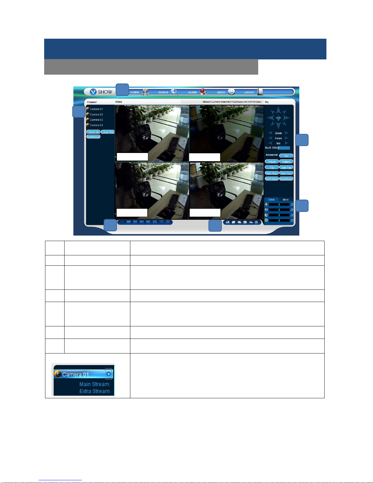
(
Item Function Description
1 Channel Channel selection.
2 Function key
Local playback: playback local recording
Open all: Displa y live views in survei llanc e win do w
3 Surveillance window Change window layout
4
Image color & other
saturation
Image color: modify brightness, contrast, saturation and hue
Other: set capture path, recording download path and reboot
5 P/T/Z control P/T/Z control menu
6 Menu System configuration, recording search, alarm setting, exit, etc.
Channel Choices
In the web interface, select the focus window in the live window. The focus
window has a light blue border. From the left channel column, select the
channel.
Remote Surveillance
LIVE VIEW WEB INTERFACE
Camera 01
Camera 02
Camera 04
Camera 03
1 2 3
4
5
6
Page 49
SHIELD DVR User Manual
48
Click on the area in upper right c orner. This allows you to choose to o pen or close the c hannel to the m ain
stream or secondary stream. It also displays the current DVR's IP address and transfer rate.
The lower left corner shows the current video feed’s channel name.
The upper right corner shows the current video feed’s time display.
Click “ ”(Lower left corner of the display window) to switch between single screen and
multi-screen views.
The function icons are located in t he lower right corner of the
display window. The six icons represent the functions below.
Area Zoom: Video images can be enlarged.
Multi-Screen switch: Switch from a single screen to
multi-screen views and vice versa.
Local Record: Saves and records vid eo to a local hard
disk while in live view. Set up the r ecording path in the
Configuration menu.
Capture: Captures the present video channel. Set up the
path to other file
Sound: Turns audio on or off.
Video Off: Turns off the in focus live view window.
Remote Surveillance
LIVE VIEW SYSTEM OPERATION
Page 50
SHIELD DVR User Manual
49
P/T/Z CONTROL
Set the P/T/Z protocol, (see Setting】→P/T/Z Configuration】) earlier in this
manual.
Control a P/T/Z camera’s direction, step size, zoom, iris, preset, tour, pattern,
border scan, light, wiper and auto pan, etc.
Step size controls P/T/Z direction and speed, e.g. a step size of 8 moves faster
than a step size of 1.
Eight directional rotations: up, down, right, left, upper left, upper right, lower left,
lower right.
Border scan
Operation: Select th e camera l ine scan of the left/rig ht margin us ing the direc tion
controls, and click the Settings button in the left /right margin position to determine
the left border.
Preset
Operation: Modify a preset position by using the directional buttons and inputting a
preset number, then click “Add” to save.
Auto Tour
Operation: Select “T our” . Point between the first crui se line and c ruis e input box
value. Input num bers in “Path” and “Pres et”. Click Add Pr eset】 to add a preset
value to the cruise path, and repeat to add additional presets. Click Clear Preset】
to delete a preset. Repeat this step to delete more presets.
Pattern Operation: Click “Pattern” in ord er to record an autom ated pattern. Then go b ack
to the P/T/Z controls to m odif y the zoom , foc us and iris , etc. St op recor din g in th e
“Pattern” setting to save the pattern.
AUX Open
Turn auxiliary components on and off.
Light Wiper
Turn the Light Wiper protocol on and off.
Remote Surveillance
LIVE VIEW SYSTEM OPERATION
Page 51
SHIELD DVR User Manual
50
CONFIGURATION
Access the DVR’s local co nfiguration
menu by clicking Configuration. For
further details please refer to Local
operation guide.
SEARCH RECORD
Click “Search” to open the search
window. You can search and operate
recordings, alarms, motion detect ion,
and local recordings.
By selecting the recording type,
starting
and ending times, and
clicking the search
button, you can
obtain a list of recorded files on the
DVR. Select the desired file and it
can be played or download ed.
Remote Surveillance
LIVE VIEW SYSTEM CONFIGURATION
Page 52
SHIELD DVR User Manual
51
Play
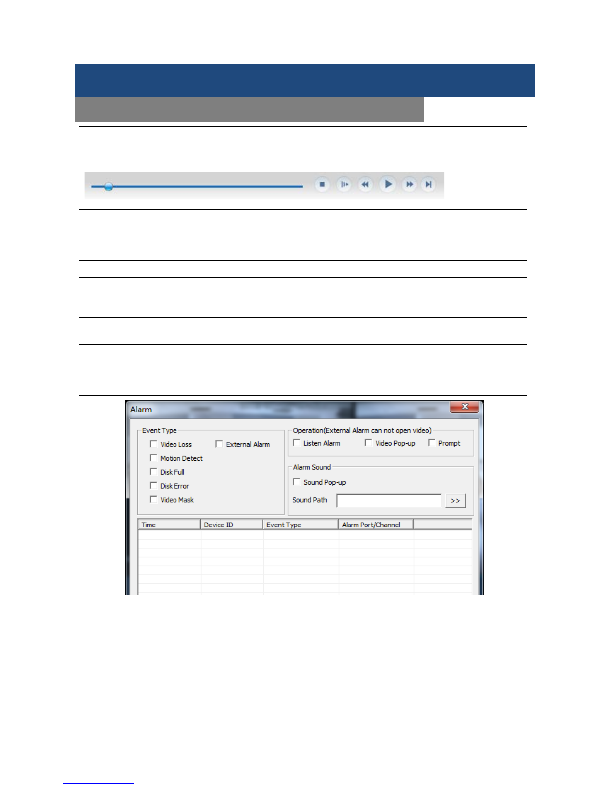
Double-click a search result to play it in the video window. Control the video playback by using the control
icons. A set of standard video playback control icons will display at the bottom of the video window.
Download
Select a searched video to download. The download speed and percentage are displayed on the bottom of
the screen.
ALARM CONFIGURATION
Alarm
Enter the alarm setup m enu. You can set up and operate the alarm functions. Choose
the type of alarm in the m enu; monitor vid eo loss, m otion detection, disk full, disk error,
video mask, and external alarms.
Video Pop-up
Open the video loss, motion detection, hard disk full, hard disk failure, video block, video
encoder, alarm pop-up.
Prompt
Open the prompts. When an alarm occurs in real-time it pops up an alarm window menu.
Sound
Pop-up
Check box and you can choose an alarm tone that is pre-recorded on the local hard drive
and will play when an alarm occurs. The alarm tone files are in the WAV format.
Remote Surveillance
LIVE VIEW SYSTEM CONFIGURATION
Page 53

SHIELD DVR User Manual
52
Summary
The Voice Intercom function enables the DVR bidirectional communication: The User can talk and listen using
the provided remote client software or over the Web via the DVR’s audio input and output ports.
There are two types of bidirectional communication, sharing and standalone. These vary by model. Please
refer to your DVR specifications to determine which is supported for your model.
Configuration
Local Configuration
Connect a microphone to the MIC input port and connect a pair of speakers to the audio output port.
If there is no standalone MIC input port, please connect a microphone to the Number 1 audio input port of the
DVR.
Note: The audio needs to be connected to a powered audio output device.
Remote PC Configuration.
Connect a microphone and powered speakers to the computer.
Enable bidirectional communication in the client software or the Web interface.
Hard Disk redundancy
The hard disk drive (HDD) redundancy function can backup recorded files. The User can then retrieve files
from a redundant HDD if a single HDD is damaged. This enhanced system data safety.
The HDD redundancy function performs a double backup of data from the designated channel to the HDD, so
the DVR needs a standalone hard disk for the redundancy function to be effective.
Hard Disk Redundancy Configuration
Open the Main Menu and then the Storage menu to access storage configuration. Select a HDD as the
redundant drive, and then click on Setting.
The Redundancy HDD must be an independent drive. The User can set several hard disks as a redundancy
HDD group. Once an HDD is assigned as a redundant HDD, recorded data can be saved to both the main
HDD and the redundant HDD.
The data on the redundant HDD should be automatically cycled; the cycle period depends on the recording
data and the capacity of the redundant HDD.
Note: Make sure there are two HDDs, with at least one in the DVR. One is for read and write and the other for
redundancy (only for RSCM-0916B081).
Channel Redundancy Configuration
The User can choose some or all of the channels to back-up. Go to Configuration】→Record】 and choose a
channel, then check the Redundancy】 box.
Note: Data can only be saved to a normal read/write HDD if Redundancy is not enabled.
Retrieve HDD Redundancy
The User can retrieve backup recordings from the back-up HDD when the main R/W HDD is damaged or data
is lost. First, shut down the DVR and remove the damaged HDD, then restart DVR. Next, go to Main menu→
Storage and set the back-up (redundant) HDD as the main read/write HDD, after which it can be searched.
Reference
VOICE INTERCOM
HARD DISK REDUNDANCY
Page 54
SHIELD DVR User Manual
53
S.M.A.R.T, or “Self-Monitoring, Analysis and Reporting Technology”, is a hard disk technology that is
incorporated into some hard disk drives. A S.M.A.R.T HDD can anal yze the drive’s head, disc, motor, circuit
operation, history and default security values via monitoring instructions in the HDD and the surveillance
software. An alarm will automatically be sent to the user when a value is outside the scope of the security
situation. Detection parameters for a Seagate HDD, for example, are divided into seven parts: ID detection
code, Attribute Description, Threshold, Attribute Value, Worst, Date, and Status.
1. ID Detection Code
ID detection codes are not uniform; different manufacturers may assign varying attributes to an ID code or
increase/decrease the quantity according to the detected parameter’s quantity. For example, an ID detection
code for Western Digital HDDs is “04”, and the procedure is Start/Stop Count, but the procedure for the same
code in a Fujitsu HDD is the “number of times the spindle motor is activated”.
2. Attribute Description
Attribute Description: Name of detectable item. The manufacturer can increase or decrease the rates. As an
ATA standard there are constant updates, sometimes different models of the same brand may be quite
different, but it is a must to ensure that the major test items are specified by S.M.A.R.T. (although different
manufacturers may have differing names, the essence of the monitoring is the same.)
1 Read Error Rate
9 Power-on Hours Count
198 Disconnection beyond repair
2 Spin up Time
10 Spin-up Retry Count
199 CRC cyclic redundancy check
4 Start/Stop Count
194 Power temperatures
200 Write Error Count
5 Relocated Sector Count
195 ECC on the Fly count
7 Seek Error Rate
197 Current Pending Sector Count
Note: Different manufacturers and different models have different attribute descriptions. The user does not
need to know the exact meanings, and attribute detection values are good enough.
3 Threshold
This is specified by a manufacturer-calculated formula. If there is an attribute valu e lower than the threshold,
this means the HDD has become unreliable and could easily lose data stored on it. The composition and
size of reliable attribute values are different for different HDDs. It should be noted that the ATA standard only
provides some S.M.A.R.T. parameters; it does not provide specific values. A "Threshold" value is determined
by the manufacturer based on the product’s features. Thus, results produced by the manufacturer’s detection
software are very different from testing software in Windows (such as AIDA32).
4 Attribute Value
Attribute value is the maximum normal value; the general range is from 1 to 253. Typically, the maximum
attribute value is 100 (for IBM, Quantum, and Fujitsu) or 253 (for Samsung). Of course, there are some
exceptions, for example, some models produced by Western Digital have t wo differ ent attr ibute values, and
the property value is set to 200 during production, but after that it is changed to 100.
5 Worst
The worst value is the largest non-normal value in the normal operation of an HDD. It is a value calculated for
an HDD’s cumulative running. It is constantly refreshed according to the drive’s running cycle, and it is very
close to the threshold. Whether or not the HDD is normal by S.M.A.R.T analysis is based on the comparison
with the threshold value. The maximum value appears when using a new HDD, which continues to decrease
with everyday use or if an error happens. Consequently, larger attribute values mean better quality and higher
reliability and smaller values mean a greater possibility of failure.
6 Dates
Actual values of an HDD’s detection of items; many of the values are cumulative values.
7 Status
The drive Status is current when all of the HDD’s attributes are analyzed and compared by the S.M.A.R.T.
system. It is also important information to judge if the HDD is healthy or not. There are three Status states:
Normal, Alarm and Error, which are closely related to the Pre-failure/advisory BIT.
Reference
HDD S.M.A.R.T
Page 55

SHIELD DVR User Manual
54
Dual-stream
Dual-stream: one high bit rate stream for the local HDD for storage QCIF/CIF/2CIF/DCIF/4CIF coding; one
low bit rate stream for network transmissions, such as QCIF / CIF coding.
I Frame
I frame: intra-frame images, removes redundant information to compress the transmittable data, also known
as key frames.
B Frame
B frame: According to a time redundancy of the source image sequence, the previously encoded frame
accounts for the source image after the encoded frame is compressed, also known as the bi-directional
prediction frame.
P Frame
P-frame: Image frames are lower quality than the previous B Frame, also known as predicted frames.
Wide Dynamic
Bright parts and dark parts in particular can be seen very clearly at the same time. Wide dynamic range is a
ratio between the brightest luminance signal value and the darkest value.
S.M.A.R.T.
S.M.A.R.T. (Self Monitoring, Analysis and Reporting Technology): No w widel y us ed in hard disk data security
technology, a monitoring system analyzes motor, circuit, HDD and disk head when a HDD is running, and
warns you when there is an abnormality.
CVBS
Composite Video Broadcast Signal, consists of luminance and color signals from the composite baseband
signal.
BNC
Coaxial cable connector, composite video signals or audio signals, commonly use 75 ohm connectors. BNC
welding is used and you should inspect the strength of the weld and remove burrs, or the signal wire and
shield’s contacts will lead to a substantial decrease of signal strength.
Reference
TERMS
Page 56
SHIELD DVR User Manual
55
HDD Capacity Calculation Reference
When first installing the DVR, check if the DVR’s internal HDD has been properly installed.
There is no capacity limitation for the DVR’s internal HDD, choose an appropriate capacity HDD according to
your recording requirements.
HDD Capacity Formula:
HDD Recording Capacity = number of channels × time in use (hours) × HDD space used per recording hour
(MB/hour)
You can calculate the formula for recording time:
annelAmountofChhrrHourcupationpeCapacityOc
pacityTotalHDDCa
hourtimeR
×=)(
)(
)(
MB/
MB
ecording
Note: 1GB=1000MB, not 1GB=1024MB, so the HDD capacity shown in Base Conf iguratio n under HDD
Management is really less than w hat it is marked.
File size per hour (CBR).
Bit Rate File Bit Rate File Bit Rate File
96k 42M 320k 140M 896k 393M
128k 56M 384k 168M 1.00M 450M
160k 70M 448k 196M 1.25M 562M
192k 84M 512k 225M 1.50M 675M
224k 98M 640k 281M 1.75M 787M
256k 112M 768k 337M 2.00M 900M
File size is more unpredictable when using VBR; please refer to the real size of the recorded file.
Hard disk problem
Use Detection Tools provided by the HDD manufacturer to detect HDD malfunctions and solve the problem.
We recommend Seagate and Western Digital drives.
How to Detect A Seagat e HDD
a) Go to www.seagate.com
. Click Support & Downloads choose Sea Tools, download the tool, as below
b) Double-click to install the downloaded file; then click on the installed file to detect HDD information of the
PC.
c) Choose the HDD for detection (other manufacturer’s hard disk are suitable too) .
Reference
HDD CAPACITY CACULATION
Page 57
SHIELD DVR User Manual
56
How to Detect Western Digital HDDs
a) Go to www.wdc.com
, choose WD support / download / SATA&SAS / WD Caviar / GP then download the
software as shown below.
b) Click on the icon for hard disk detection after downloading.
c) Double-click on the hard disk in the device lis t
Reference
HDD CAPACITY CACULATION
Page 58

SHIELD DVR User Manual
57
DVR startup failure or continuous reboot
Possible reasons:
1. The system has been damaged by a bad DVR update.
2. There is a problem with the DVR main board, please contact Rosewill.
3. There is an HDD error. Replace the f ault y HDD.
Remote control does not work
Possible reasons:
1. Check if the batteries in the remote control are installed properly.
2. Check the battery life.
3. Check if the remote receiver is blocked by any objects.
4. Check if the DVR address corresponds to the remote control address.
DVR cannot control P/T/Z Camera
Possible reasons:
1. RS-485 cable is connected wrong. The A and B cables might be inversely connected.
2. P/T/Z decoder, protocol, baud rate or addresses are not correct.
3. Parallel connect a 120Ω resistor to resolve signal reflex caused by too many P/T/Z cameras on the line.
4. The RS-485 port on the DVR is defective.
Blurred screen in preview mode
Possible reasons:
Make sure your camera’s settings match the DVR’s video settings. If a camera is set to the NTSC standard
but the DVR is set to the PAL standard, the preview will be blurred.
Blurred screen in playback mode or failure to p lay back recordings
Possible reasons:
1. Procedure error, reboot the DVR.
2. HDD error, test or replace the HDD.
3. DVR hardware failure, contact Rosewill.
Cannot connect to DVR through network
Possible reasons:
1. Check if the network connection is correct.
2. Check if the DVR network configuration parameters are correct.
3. Check whether IP address conflicts exist in the network.
Downloaded recording cannot be played
Possible reasons:
1. Player installation error.
2. The USB or HDD device has an error.
3. Do not install graphic software later than DirectX 8.1.
Reference
COMMON FAULTS
Page 59
SHIELD DVR User Manual
58
Possible reasons:
Close Internet Explorer, restart it, access Internet Options from the Tools menu and go to the Advanced tab.
Make sure the memory protection item is not enabled. See the following:
IE TOOL BAR
Internet Explorer 9.0 or above
Please use a compatible mode if you are having difficulty with your IE browser.
Reference
INTERNET EXPLORER CRASH
Uncheck box
 Loading...