

Page 1

Page 2

POWER SUPPLY Value series
Contents
User Manual
Features Descriptions
Specification
Installation
1. Installing Power Supply
2. 20+4 pin Main Connector
3. 4 pin 12V Connector
4. 6 pin PCI-Express Connector
5. 4 pin Molex Peripheral Connector
6. 4 pin Floppy Connector
7. 5 pin SATA Connector
8. Before starting your system
Information
P. 2
P. 3
P. 7
P. 7
P. 8
P. 8
P. 9
P. 9
P. 9
P. 1 0
P. 1 1
© 2004-2006 Rosewill Inc. All rights reserved by Rosewill
1
Page 3
POWER SUPPLY Value series
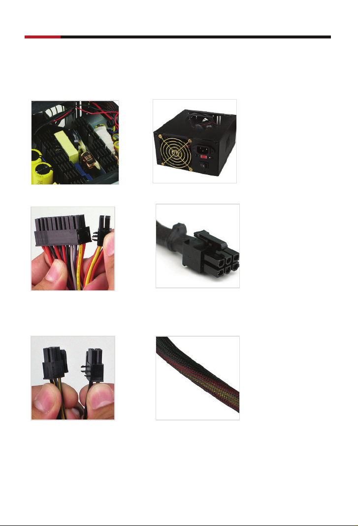
Features Descriptions
User Manual
• ATX V2.01 Dual 12V Rails
• 20+4 pin Main Connector
• 4/8-pin +12v and EPS
Connector
• Dual 80mm Fans
• 1 x PCI-Express Connector
• All cables with black mesh sleeving
© 2004-2006 Rosewill Inc. All rights reserved by Rosewill
2
Page 4
POWER SUPPLY Value series
Specifi cation
Connectors
RV380-2-FRB-S
• 20+4 pin Main Connector x 1 • 4+4 pin Connector x 1
* 8 pin = +12V EPS Connector
4 pin = +12 V Connector
User Manual
• 6 pin PCI-Express Connector x 1
• 4 pin Peripheral Connector X 6
• 5 pin SATA Connector x 2 • 4 pin Floppy Connector x 2
© 2004-2006 Rosewill Inc. All rights reserved by Rosewill
3
Page 5
POWER SUPPLY Value series
RV430-2-FRB-S, RV480-2-FRB-S
User Manual
• 20+4 pin Main Connector x 1
• 4+4 pin Connector x 1
* 8 pin =+12V EPS Connector
4 pin = +12 V Connector
• 6 pin PCI-Express Connector x 1
• 4 pin Peripheral Connector X 8
• 5 pin SATA Connector x 2 • 4 pin Floppy Connector x 2
© 2004-2006 Rosewill Inc. All rights reserved by Rosewill
4
Page 6

POWER SUPPLY Value series
Input
AC Input Voltage : 115V/230V
AC Input Frequency : 50/60HZ
AC input Current :
RV380-2-FRB-S 6.0A(RMS) 4.0A(RMS)
RV430-2-FRB-S 7.0A(RMS) 4.5A(RMS)
RV480-2-FRB-S 8.0A(RMS) 5.0A(RMS)
115V 230V
Output
RV380-2-FRB-S
Voltage +3.3V +5V +12V1 +12V2 -12V +5VSB
MAX.Current 30A 28A 14A 15A 0.6A 2A
MAX.Watt 130W 233W 7.2W 10W
Total Watt 380W
Regulation ±5% ±5% ±5% ±5% ±10% ±5%
Noise & Ripple
(mV)
100 100 120 120 200 100
RV430-2-FRB-S
Voltage +3.3V +5V +12V1 +12V2 -12V +5VSB
MAX.Current 30A 29A 14A 15A 0.6A 2A
MAX.Watt 140W 273W 7.2W 10W
Total Watt 430W
Regulation ±5% ±5% ±5% ±5% ±10% ±5%
Noise & Ripple
(mV)
100 100 120 120 200 100
User Manual
RV480-2-FRB-S
Voltage +3.3V +5V +12V1 +12V2 -12V +5VSB
MAX.Current 30A 30A 15A 15A 0.6A 2A
MAX.Watt 150W 313W 7.2W 10W
Total Watt 480W
Regulation ±5% ±5% ±5% ±5% ±10% ±5%
Noise & Ripple
(mV)
100 100 120 120 200 100
5
© 2004-2006 Rosewill Inc. All rights reserved by Rosewill
Page 7

POWER SUPPLY Value series
Overall Performance
Efficiency :70% at typical full load and norminal input voltage
Hold-Up Time : 17ms at full load and norminal input voltage
Switching Frequency : 60HZ at norminal input.
Stability : ±10%, for 24 hours after warm up.
Protection
Over Load Protection :150% over load protection
Over voltage protection : Main output over 20% protection
Short Circuit Protection : All output equipped with short circuit
protection
Environment
Operation Temperature : 0°c to +40°c
Storage Temperature : -40°c to +70°c
Operating Humidity : 10% to 90% RH
Storage Humidity : 10% to 90% RH
Safety standards
TUV/CE/CB/FCC/UL
EMI Standard
Meet with FCC class B and CISPR-22B
HI-POT Testing
Input to ground : 15KVac/10mA 3 second
Input to output : 15KVac/10mA 3 second
User Manual
Insulation resistance
Input to ground : Min 50M
Input to output : Min 50M
Reliability
MTBF : 50000 hours at 25°c ambient temperature
© 2004-2006 Rosewill Inc. All rights reserved by Rosewill
6
Page 8

POWER SUPPLY Value series
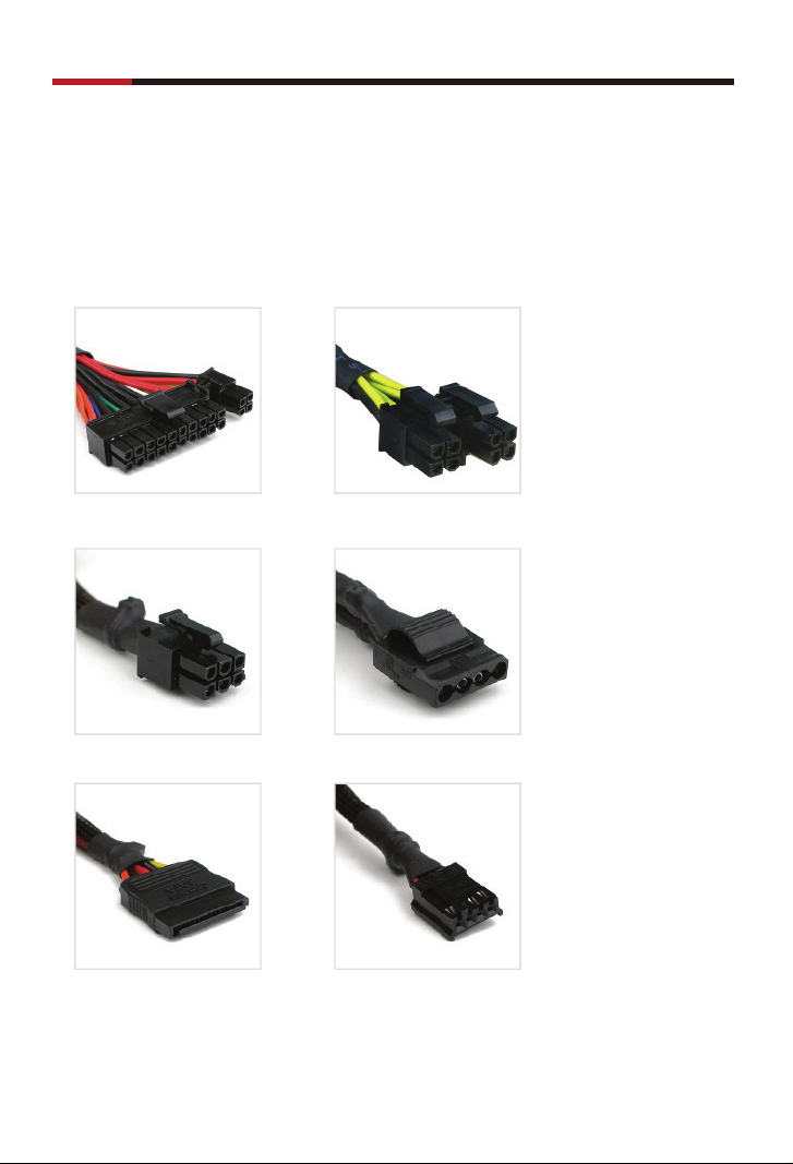
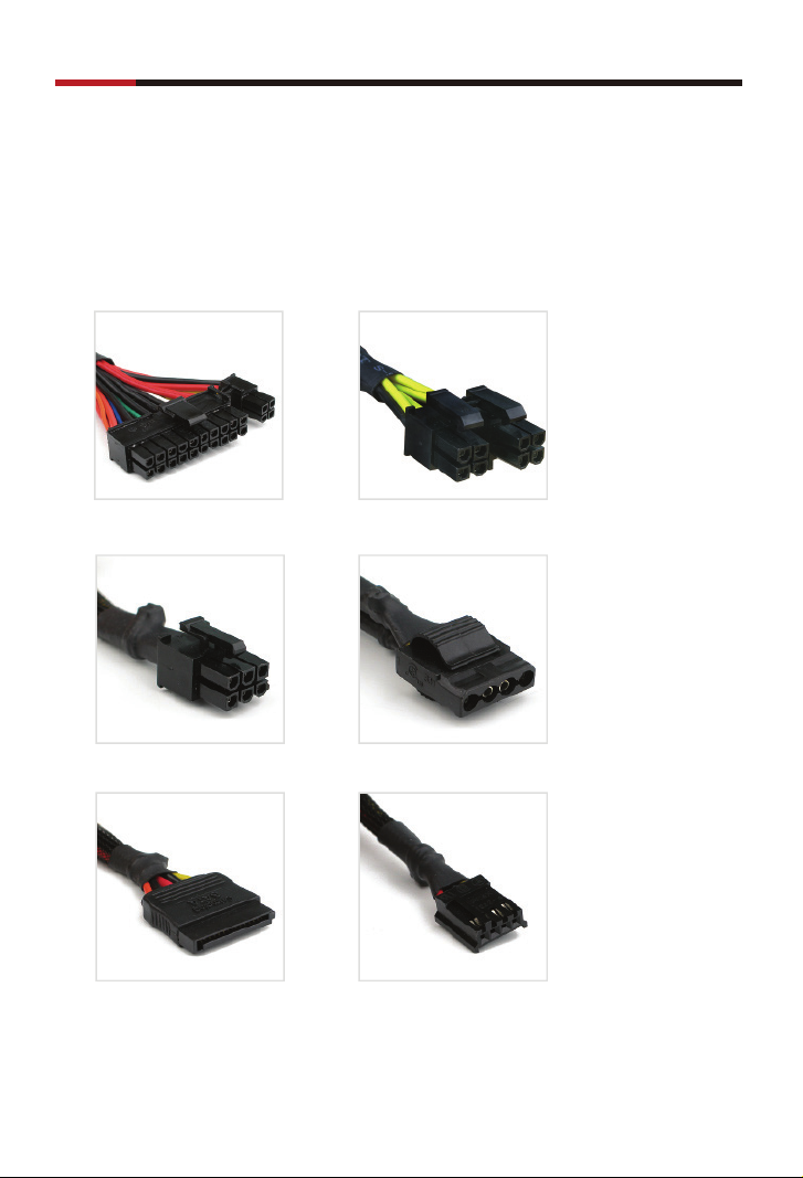
Installation
1. Installing Power Supply
• Affi x the power supply to the case with screws.
2. 20+4 pin Main Connector
• Detach the 4 pin section to have a 20
pin main connector
User Manual
• Attach the 4 pin section to have a 24
pin main connector
• Plug the 20 pin connector onto the
motherboard.
• Plug the 24 pin connector onto the
motherboard.
NOTE :
1. Confi rm 20 pin or 24 pin main connector your motherboard needs before the installation.
2. 4 pin section here is used for switching between 20 & 24 pin only.
© 2004-2006 Rosewill Inc. All rights reserved by Rosewill
7
Page 9

POWER SUPPLY Value series
3. 4+4 pin Connector
User Manual
8 pin4 pin
• Separate the 8 pin EPS +12V
connector to have two 4 pin
connector
• Pick anyone 4 pin +12V
connector to plug onto the
motherboard
• Combine two 4 pin connectors
to have a 8 Pin EPS +12V
connector
• Plug the 8 pin EPS +12V
connector onto the
motherboard.
NOTE :
1.Confi rm 4 pin +12V or 8 pin EPS +12V connector your motherboard needs before
the installation.
2.4 pin here CAN NOT be used for the main connector..
© 2004-2006 Rosewill Inc. All rights reserved by Rosewill
8
Page 10

POWER SUPPLY Value series
4. 6 pin PCI-Express Connector
• The 6 pin PCI-Express connector for video card only.
NOTE :
Confi rm if your video card needing the 6 Pin PCI-Express connector or not
before the installation. Not every video card needs it.
5. 4 pin Peripheral Connector
• The 4 pin Molex Peripheral connector used for HDD,
Optical Drive and other devices needing it.
User Manual
© 2004-2006 Rosewill Inc. All rights reserved by Rosewill
9
Page 11

POWER SUPPLY Value series
6. 4 pin Floppy Connector
• The 4 pin Floppy connectors used for
Floppy disk or Zip drives.
7. 5 pin SATA Connector
• 5 pin SATA connector used for SATA
HDD and Optical Drive.
User Manual
© 2004-2006 Rosewill Inc. All rights reserved by Rosewill
10
Page 12

POWER SUPPLY Value series
8. Before starting your system
User Manual
• Select the proper voltage
setting.
• Connect the power core to a
power source.
•Confi rm the power supply is on
• Attach the power core to the power
supply
off on
© 2004-2006 Rosewill Inc. All rights reserved by Rosewill
11
Page 13

Page 14

 Loading...