

Page 1

SERVER RSV-Z4000
USER Manual
Page 2
SERVER RSV-Z4000
INDEX
Introduction
User Manual
02
Specifications
Top Cover Disassembly
5.25" Device Installation
3.5" Device Installation
Fan Filter Replacement
Fan Replacement Installation
Motherboard Installation
Power Supply Installation
USB cable Instructions
Accessory Kit Index
LED Indicators Illustration
02
03
03
06
07
07
08
09
11
11
11
1
Page 3

SERVER RSV-Z4000
Introduction:
RSV-Z4000 RACKMOUNT CHASSIS
The RSV-Z4000 is a 19" rackmount industrial grade server PC, which is
designed for extended ATX form factor server board and can be equipped with
PS2 power supply or mini-redundant power supply. In addition, the RSV-Z4000 has a
large-scale fan filter and a easy-to-use knob key for great serviceability of the
system.
Specifications:
• Construction: Heavy-duty 1.2mm steel chassis
• Disk Drive Capacity :
- Right / Left(Standard) : 5.25" x 3 (or D340) + 3.5" x 1
- Middle : 3.5" x 2
- Lefe side: 5.25" x 3 (or D340) + slim CD x 1 or
Internal HDD x 5 + slim CD x 1 (w/12cm) fan
• Cooling System : Onefront 12cm (optional) and two rear 8cm cooling fans
• Controls : Momentary power, recess reset switches
• Optional front USB dual socket
• One-screw-fastened top cover design
• Indicators : LED display for power and HDD ǵLAN ǵFan fail
• Dimensions (WxDxH) : 483 X 560 X 177
• Power Supply : PS2 / Mini Redundant
User Manual
2
Page 4
SERVER RSV-Z4000
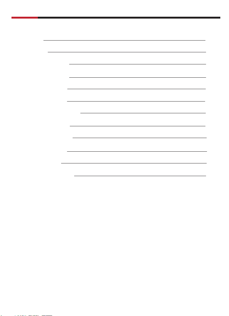
Top Cover Disassembly
User Manual
1.Release the thumb screws of
2.Slide back the lop cover and lift up
the top cover
2
5.25” Device installation
(A) 5.25” cage disassemblly
1.Release the screws of the cage 2.Lift up the cage
1
1
2
(B) Dismount the front cover plate
1
1.Release the screws of the metal cover
2.Remove the metal cover plate from 450 angle
3
Page 5

SERVER RSV-Z4000
(C) CD-ROM installation
User Manual
1.Place CD-ROM in the disk cage
1
3.Place the disk cage back to the case
3
(D) Other device installation
2.Affix the CD-ROM to the disk cage
with screws
2
2
1.Place D340 in the disk cage
1
2.Affix the D340 to the disk cage
with screws
4
Page 6

SERVER RSV-Z4000
(E) HDD&FDD installation in 5.25” device cage
a.
1.Fix the HDD bracket with HDD first
1
2.Place HDD set in the disk cage
3.Affix the HDD bracket to the
disk cage with screws
User Manual
2
b.
1.Place FDD in the lower disk cage
2.Affix the FDD to the disk cage with screws
2
1
(F) Slim CD-ROM installation
1.Place slim CD-ROM in the lower disk cage
2.Affix the slim CD-ROM to the disk cage with screws
c.
1.Place HDD in the lower disk cage
2.Affix the HDD to the disk cage
with screws
2
1
5
Page 7

SERVER RSV-Z4000
1
User Manual
3.5” Device installation
(A) 3.5” cage Dismount
1.Release the screws from 3.5” cage 2.Pull out and dismount the 3.5” cage
1
2
(B) Metal cover plate dismount
1.Release the screws of metal
1
cover plate
2
(C) 3.5” device installation
1.Place FDD into the 3.5” cage and affix
with screws
2.Dismount the cover plate from
0
45
angle
2.Mount the 3.5” cage with screws
2
6
Page 8
SERVER RSV-Z4000
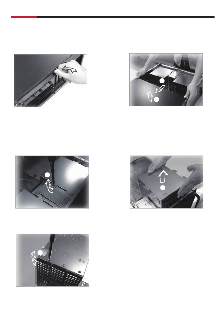
Fan filter replacement
3
Fan replacement installation
(A) 12cm fan replacement
User Manual
1.Pull out the filter bracket and remove
the used filter
2.Replace with new fan filter
3.Mount the filter bracket
1.Release the screws from fan bracket
on 5.25” device cage
1
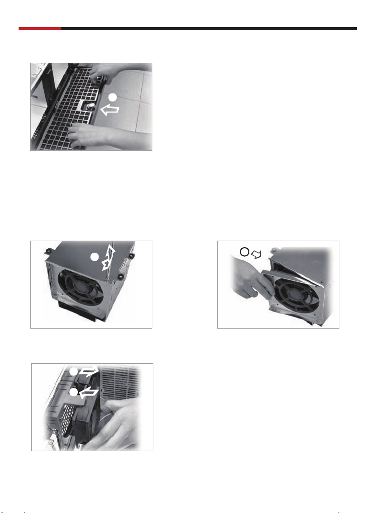
(B) 8cm fan replacement
1
2
2.Pull out and remove the fan from cage
3.Replace with the new fan
2
1.Remove the 8cm fan from fan holder
2.Replace with the new fan
7
Page 9

SERVER RSV-Z4000
Motherboard installation
(A) Interface card bracket installation
3
1.Release the screws from bracket
2.Remove the bracket from 450 angle
(B) Motherboard installation
1.Affix the standoffs on the M/B base 2.Place the motherboard on the
standoffs and affix with #6-32
screws
User Manual
1
8
2
Page 10

SERVER RSV-Z4000
(C) Interface installation
1.Plug the interface card to the motherboard slot
1
2.Affix the interface card bracket to the case by screw
User Manual
1
2
3.Loose the thumb screws to adjust the hold down clamp to the interface card
3
Note : Do Not take the screws out
9
Page 11

SERVER RSV-Z4000
4.Affix the hold sown clamp with thumb screws
2
Power supply installation
1
User Manual
1.Place the power supply into the case
2
2.Affix the power supply with screws
10
Page 12

SERVER RSV-Z4000
User Manual
USB cable instructions:
Pin-Connection of USB cable
1. Please check before installation, you can use the USB-Station on your Motherboard.
Please take a look on the manual of your Motherboard and search the note
“option 4 x USB”. You see on the motherboard a connector for the USB-Cable.
It’s not so important how many pins you can see, lot of manufactures have a different
design for the USB connector.
2. Each pins has a function. please see the following list, and find the colors for
the installation.
3. Have you any problems with the installation, please contact www.rosewill.com.
We cannot give any quarantee
when the components damaged by yourself.
Colors and Connection
This is a universal cable. this means, it’s not so important how much pins on the
motherboard 8, 9 or 10.
• Red
• Black
• Black
• Grey
• Yellow
• Red
• Green
• White
= V1
= Ground
= Ground
= D1+
= D1-
= V0
= D0+
= D0-
Accessory kit index
1. # 6-32 Screws x 32
2. M3 Screws x 22
3. Cable Strap x 6
4. Adhesive Backed Mount x 5
5. Brass Stud ( 8mm ) x 20
LED indicators illustration
• Power on in green LED
• HDD activity in orange LED
• Fan fail in red LED
• Lan or system activity in green LED
11
Page 13

www.rosewill.com
Thank you for purchasing a quality Rosewill Product.
Please register your product at : www.rosewill.com for complete warranty information and future support for your product.
 Loading...