

Page 1
1
Internet Camera
Advanced Installation Guide
Page 2

2
Contents
CHAPTER 1
Product Overview
1.1 PACKAGE CONTENTS ............................................................................................................ 4
1.2 INTRODUCTION ..................................................................................................................... 5
1.3 FEATURES ........................................................................................................................... 7
CHAPTER 2
Hardware Installation
2.1 INSTALLING THE CAMERA STAND ......................................................................................... 10
2.2 CONNECTING THE CAMERA TO LAN/WLAN ......................................................................... 11
2.3 APPLICATIONS OF THE CAMERA ........................................................................................... 12
Chapter 3
Software Ins tallation
3.1 IPFINDER........................................................................................................................... 13
3.2 ACCESSING TO THE CAMERA ............................................................................................... 14
3.3 CONFIGURING THE IP ADDRESS OF THE PC ......................................................................... 17
Chapter 4
Configuring the Camera
4.1 WEB CONFIGURATION ........................................................................................................ 18
4.2 SMART WIZARD .................................................................................................................. 19
4.3 BASIC SETUP ..................................................................................................................... 22
4.4 NETWORK SETTINGS .......................................................................................................... 25
4.5 SETTING UP VIDEO & AUDIO................................................................................................ 33
4.6 EVENT SERVER CONFIGURATION......................................................................................... 35
4.7 MOTION DETECT ................................................................................................................ 36
4.8 EVENT CONFIGURATION ...................................................................................................... 38
4.9 TOOLS 41
4.10 INFORMATION ....................................................................................................................... 43
CHAPTER 5
Software Application - UltraVi ew Pro
5.1 INTRODUCTION ....................................................................................................................... 44
5.2 INSTALLATION ......................................................................................................................... 45
5.3 USING ULTRAVIEW PRO .......................................................................................................... 47
5.3.1 Starting the Program ........................................................................................... 47
5.3.2 Main Window and Item Feature .......................................................................... 48
5.3.3 Accessing the Camera ........................................................................................ 52
5.3.4 Recording / Playing Video ................................................................................... 58
5.4 CONFIGURING ULTRAVIEW PRO ................................................................................................. 63
5.4.1 Configuring the eMap View Setting .................................................................... 63
5.4.2 Configuring the System ....................................................................................... 68
Page 3

3
5.4.3 Event Configuration ............................................................................................. 69
5.4.4 Changing System Language ............................................................................... 73
5.4.5 Terminating Operation ........................................................................................ 74
CHAPTER 6
Rem ote Live View
6.1 OVERVIEW .............................................................................................................................. 76
6.2 INSTRUCTIONS ........................................................................................................................ 76
WEB:C4MI
6.2.1 User Registration .......................................................................................................... 76
6.2.2 Activating Devices ........................................................................................................ 80
6.2.3. My Device .................................................................................................................... 83
6.2.4. Setting Up Accounts .................................................................................................... 89
6.2.5. Deleting Devices .......................................................................................................... 90
APP:EAGLESENSE
6.3 OPERATING EAGLESENSE ........................................................................................................ 92
Andriod Google Play .............................................................................................................. 92
iTune App Store ..................................................................................................................... 93
6.3.2 Viewing Videos ............................................................................................................. 95
6.3.3 Viewing Images Generated from Multiple Videos ...................................................... 100
6.3.4 Exiting EagleSense..................................................................................................... 105
6.4 FREQUENTLY ASKED QUESTIONS ........................................................................................... 106
6.4.1 The webpage cannot be displayed, what should I do? .............................................. 106
6.4.2 I forgot my password, how can I reset one? .............................................................. 106
6.4.3 How do I download user client? ................................................................................. 108
CHAPTER 7
APPENDIX.
GLOSSARY OF TERMS ................................................................................................................... 109
Page 4

4
CHAPTER 1
Product Overview
1.1 Package Contents
Check the items contained in the package carefully. You should have the following:
● Wireless Internet Camera
● AC Power Adapter.
● Camera Stand.
● Ethernet Cable (RJ-45 type).
● Installation CD-ROM.
● Quick Installation Guide.
NOTE Once any item contained is damaged or missing, contact the authorized dealer of
your locale.
Page 5
5
1.2 Introduction
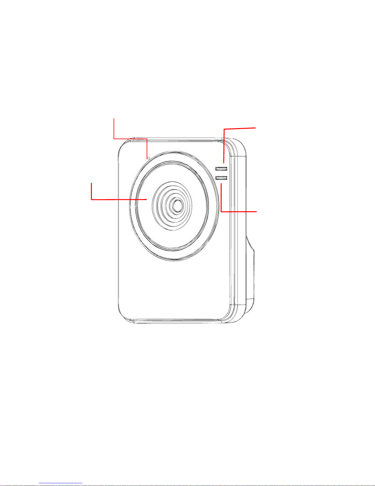
Front View
Lens Assembly
Power LED
Indicates the camera
is powered on with the
steady amber light.
Link LED
indicates the camera’s
network connectivity
with the flashing green
light.
Internal Microphone
allows the camera to
receive sound and voice.
Page 6
6
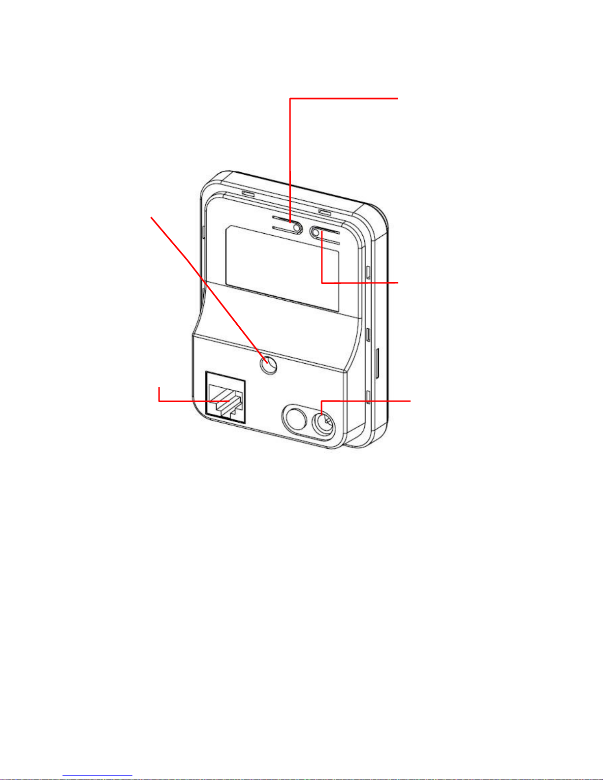
Rear View
● For more information of the WPS button, refer to the instruction of the Web
Configuration, Network >> Wireless >> WPS Setting.
Screw Hole
is used to connect
the camera stand.
Reset Button will restart
the camera when it is
pressed quickly; when it is
long pressed for five
seconds, the camera will
resume the factory default
settings.
DC Power Connector
is used to connect the
AC power adapter, in
order to supply power
to the camera.
Ethernet Cable
Connector
is used to connect
the network cable,
which supports the
NWay protocol so
that the camera can
detect the network
speed
automatically.
WPS Button* (for
wireless model)
is used to protect your
wireless network and
for easy wireless
connection setup.
Page 7

7
1.3 Features
■ MJPEG codec Supported
The camera provides you with VGA images by the MJPEG codec technology, allowing
you to adjust image size and quality, and bit rate according to the networking
environment.
■ 1-way Audio Capability
The built-in microphone of the camera provides on-the-spot audio via the Internet,
allowing you to monitor the on-site voice.
■ Remote Control Supported
By using a standard Web browser or the bundled UltraView Pro software application,
the administrator can easily change the configuration of the camera via Intranet or
Internet. In addition, the camera can be upgraded remotely when a new firmware is
available. The users are also allowed to monitor the image and take snapshots via the
network.
■ Multiple Platforms Supported
The camera supports multiple network protocols, including TCP/IP, SMTP e-mail, HTTP,
and other Internet related protocols. Therefore, you can use the camera in a mixed
operating system environment, such as Windows Vista and Windows 7.
■ Multiple Applications Supported
Through the remote access technology, you can use the cameras to monitor various
objects and places for your own purposes.
For example, babies at home, patients in the hospital, offices and banks, and more. The
camera can capture both still images and video clips, so that you can keep the archives
and restore them at any time.
Page 8

8
Specification
Model
RSCM-12001
RSCM-12002
Image Sensor
Image Sensor
1/5” Color CMOS Sensor
Resolution
640 X 480
Minimum Illumination
0.7 Lux
Lens
Digital Zoom
3x
Lens Type
Board Lens
Aperture (F/No.)
2.8
Focus Length
2.7mm
View Angel(Horizontal)
52.8 Degree
View Angel(Vertical)
39.6 Degree
View Angle(Diagonal)
66 Degree
Night Vision
IR-Cut Filter
N/A
Auto
Illumination Distance
N/A
Up To 5 Meters
Audio (One-Way)
Microphone
Built-In Omni-Directional Microphone
Sensitivity
-48db +/- 3db
Frequency
50~16000hz
Audio Codec
PCM (Audio In)
Video
Compression
MJPEG
Auto Exposure
Yes
Auto White Balance
Yes
Auto Gain Control
Yes
Resolution And Frame Rate
VGA (640 X 480 ) @ 30 FPS
QVGA ( 320 X 240 ) @ 30 FPS
QQVGA ( 160 X 120) @ 30 FPS
Networking
Network Protocols
IPV4, ARP, TCP/IP, UDP, ICMP, DHCP, NTP, DNS, DDNS, SMTP,
FTP, HTTP, PPPoE, UPnP and SSL, Bonjour
Ethernet
IEEE 802.3u 10/100Mbps Auto-MDIX Fast Ethernet
Wireless
IEEE 802.11 b/g/n Wireless LAN
Security
64/128-bit WEP, WPA / WPA2-PSK
Hardware
System ROM
4MByte NOR Flash
System RAM
32MByte SDRAM
Power LED
Orange Color
Link/Act. LED
Green Color
Reset Button
Push And Hold Over 5 Sec Will Be Factory Reset
WPS Button
Yes
RJ45 Port
X 1
Antenna
Built-In 2.5dbi Internal Antenna
Power
DC 5V / 1.2A
Power Consumption
3.5 Watts Max.
4.5 Watts Max.
Operation Temperature/Humidity
0°C ~ 45°C (32°F ~ 104°F)/20% ~ 85% (Non-Condensing)
Storage Temperature/Humidity
-15°C ~ 60°C (5°F ~ 140°F)/0% ~ 90%(Non-Condensing)
Approvals
FCC/CE class B
Dimensions (Body Only)
2.9” (W) X 3.7” (H) X 1.2” (D) / 74mm (W) X 95mm (H) X 30.5mm (D)
Weight (Body Only)
0.19lbs / 85g
Page 9

9
1.4 System Requirement
Networking
- LAN: 10Base-T Ethernet or 100Base-TX Fast Ethernet, Auto-MDIX
- WLAN: IEEE 802.11b/g/n
Accessing the Camera using Web Browser
- Platform: Microsoft® Windows® 2000/XP/Vista/Win7
- CPU: Intel Pentium III 800MHz or above
- RAM: 512MB
- Resolution: 800x600 or above
- User Interface: Microsoft® Internet Explorer 6.0 or above; Apple Safari 2 or above;
Mozilla Firefox 2.00 or above; Google Chrome
Accessing the Camera using UltraView Pro
- Platform: Microsoft® Windows® XP/Vista/Win7
- Resolution: 1024x768 or above
Hardware Requirement:
- 1~8 cameras: Intel Core 2 Duo 2GB RAM
- 9~32 cameras: Intel Core 2 Quad 4GB RAM
NOTE If you connect multiple cameras to monitor various places simultaneously, you are
recommended to use a computer with higher performance.
Page 10
10
CHAPTER 2
Hardware Installation
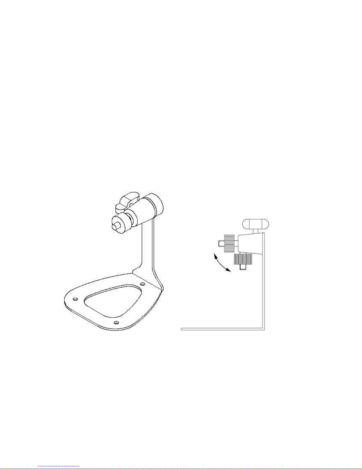
2.1 Installing the Camera Stand
The camera comes with a camera stand, which uses a swivel ball screw head to lock to
the camera’s screw hole. When the camera stand is attached, you can place the
camera anywhere by mounting the camera through the three screw holes located in the
base of the camera stand.
The Camera Stand
Page 11

11
2.2 Connecting the Camera to LAN/WLAN
Use the p your local area network (LAN).
When you connect provided Ethernet cable
to connect the camera to the AC power
adapter, the camera is powered on
automatically. You can verify the power
status from the Power LED on the front
panel of the camera.
Once connected, the Link LED starts
flashing green light and the camera is on
standby and ready for use now.
Connecting the Ethernet Cable
When the camera is powered on, the camera will automatically search any
access point with “default” SSID.
NOTE
(For wireless model) If the camera cannot to your wireless network, you need to install
the camera in LAN and proceed with WLAN settings.
Page 12
12
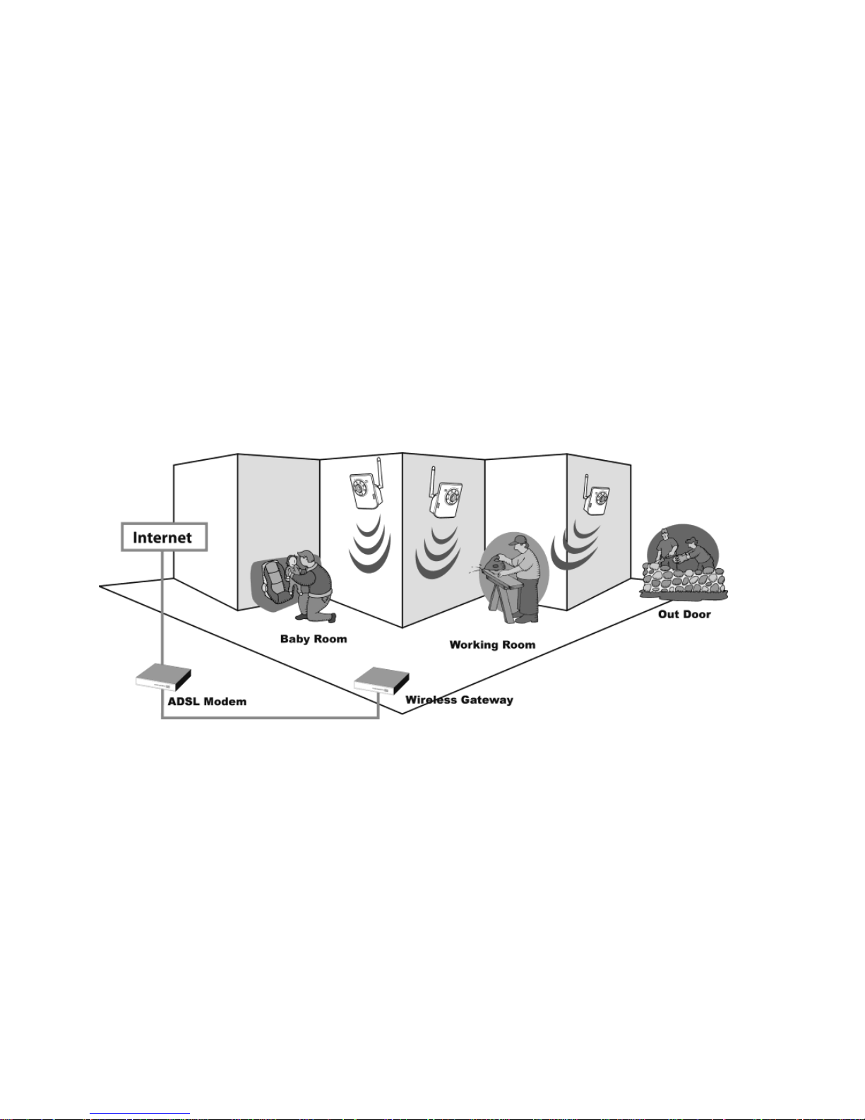
2.3 Applications of the Camera
The camera can be applied in multiple applications, including:
Monitor local and remote places and objects via Internet or Intranet.
Capture still images and video clips remotely.
Upload images or send email messages with the still images attached.
The following diagram explains one of the typical applications for your camera and
provides a basic example for installing the camera.
Home Applications
*Please enclosed by waterproof
housing when using in outdoor
*
Page 13
13
Chapter 3
Software Installation
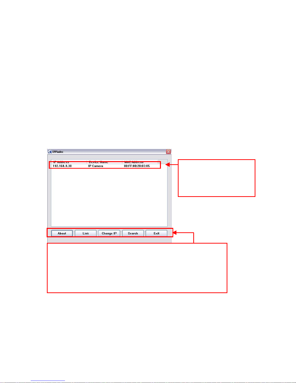
3.1 IPFinder
The camera comes with a conveniently utility, IPFinder, which is included in the
Installation CD-ROM, allowing you to search the camera on your network easily.
1. Insert the Installation CD-ROM into your computer’s CD-ROM drive to initiate the
Auto-Run program.
2. Click the IPFinder item to launch the utility. The control panel will appear as below.
3. Once you get the IP address of the camera, launch the Web browser or UltraView
Pro to access your camera.
Display the connected
camera(s)
Double click to link the
camera
Click About
to get the Version information of IPFinder.
Click
Link to connect the selected camera.
Click
Change IP
to modify the IP address of the selected camera.
Click
Search to find the IP address of the connected camera(s).
Click Exit to close the utility.
Page 14
14
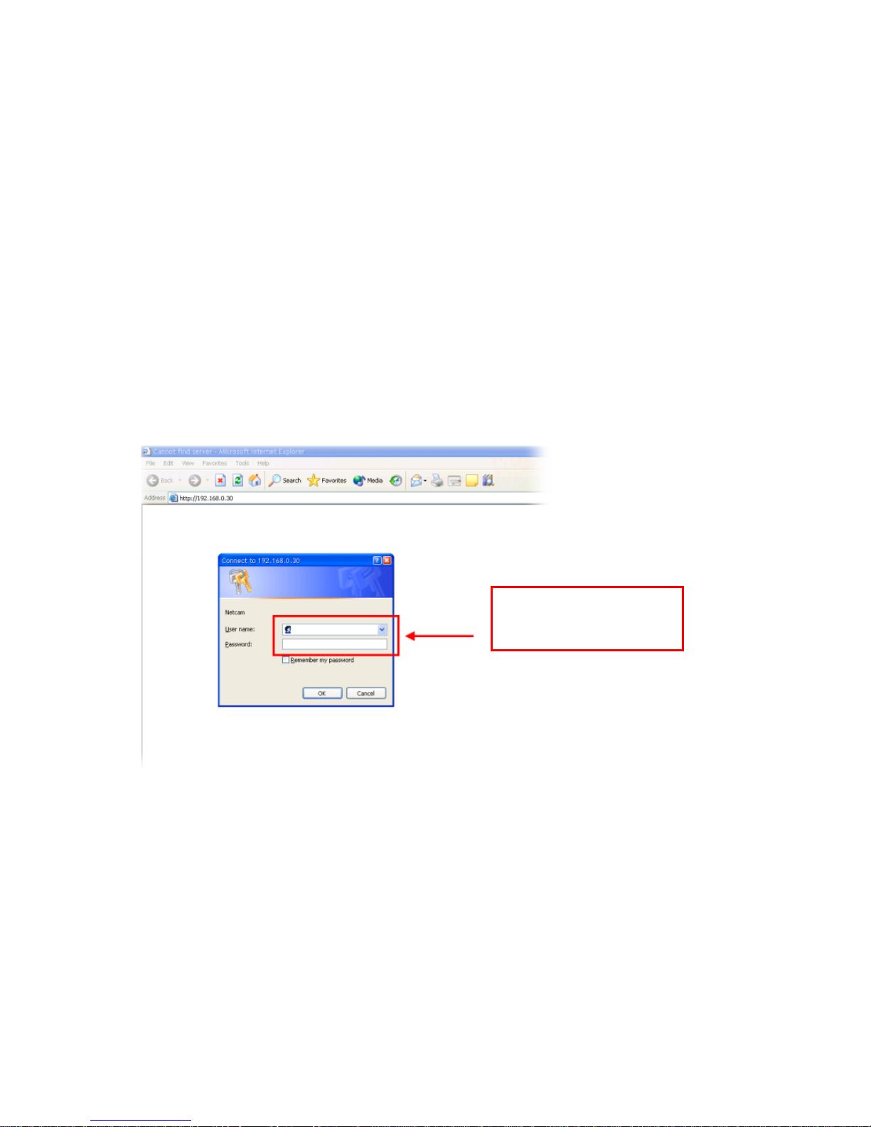
3.2 Accessing to the Camera
Whenever you want to access the camera:
1. Since the default configuration of the camera is DHCP mode enabled, you are
recommended to launch IPFinder to search the IP address that is assigned to the
camera by the DHCP server, and then click Link to access the camera via the Web
browser.
2. If Network Camera can't get IP Address under DHCP mode, the default IP Address
will be 192.168.0.30.
3. When the login window appears, enter the default User name (admin) and
password (admin) and press OK to access to the main screen of the camera’s
Web Configuration.
NOTE If you are initially access to the camera, you will be ask to install a new plug-in for
the camera. Permission request depends on the Internet security settings of your
computer. Click Yes to proceed.
Enter the User name
and Password.
Page 15
15
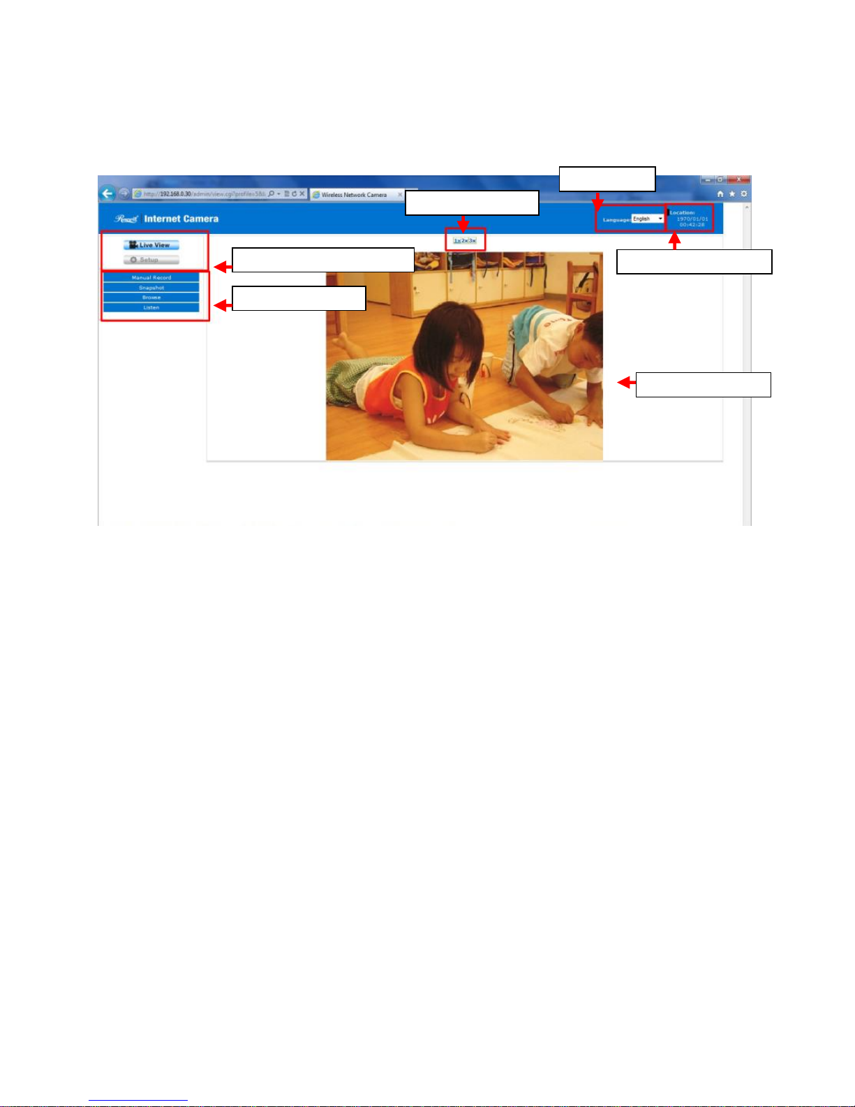
After you login into the Web Configuration of the camera, the main page will appear as
below:
he main page of the Web Configuration provides you with many useful information and
functions, including:
Camera Information – Display the camera’s location and the current date & time.
The information can be modified in the Web Configuration.
Language – Select your favorite displayed language for the system.
Live View Image – Displays the real-time image of the connected camera.
Live View/Setup Switch – Click Setup to configure the camera. For details, see
Chapter 4 and Click the Live View button to return to the Main screen to view the
live view image.
Function Buttons – Use these buttons to control the video functions.
Manual Record allows you to record and save a video clip.
Snapshot allows you to capture and save a still image.
Browse allows assign the destination folder to store the video clips and still
images.
Listen allows you to receive the on-site sound and voice from the camera.
Function Buttons
Live View/Setup Switch
Camera Information
Live View Image
Zoom In Buttons
Language
Page 16

16
Zoom In Buttons – Click the buttons to zoom in the live view image by 1x, 2x, and
3x.
NOTE If your PC use Microsoft Vista platform, you may be unable to find these recorded
files what stored by Snapshot or Manual Record. You need to disable the
protected mode of Security in the IE Browser. Please follow as below Steps:
1. Open IE Browser
2. Select Tools Internet Options
3. Select Security
4. Disable the “Enable Protected Mode” then press OK
Page 17

17
3.3 Configuring the IP Address of the PC
If you are failed to access to the camera, please check the IP address of your computer.
When you connect the camera to your computer directly to proceed with configuration of
the camera, you need to set up the IP addresses to be in the same segment for the two
devices to communicate.
1. On your computer, click Start > Control Panel to open the Control Panel window.
2. Double-click Network Connection to open the Network Connection window.
3. Right-click Local Area Connection and then click Properties from the shortcut
menu.
4. When the Local Area Connection Properties window appears, select the General
tab.
5. Select Internet Protocol [TCP/IP] and then click Properties to bring up the
Internet Protocol [TCP/IP] Properties window.
6. To configure a fixed IP address that is within the segment of the camera, select the
Use the following IP address option. Then, enter an IP address into the empty
field. The suggested IP address is 192.168.0.x (x is 1~254 except 30), and the
suggested Subnet mask is 255.255.255.0.
7. When you are finished, click OK.
Page 18
18
Chapter 4
Configuring the Camera
4.1 Web Configuration
You can access and manage the camera through the Web browser and the provided
software application UltraView Pro. This chapter describes the Web Configuration, and
guides you through the configuration of the camera by using the web browser.
To configure the camera, click Setup on the main page of Web Configuration. The Web
Configuration will start from the Basic page.
The Web Configuration contains the settings that are required for the camera in the left
menu bar, including Smart Wizard, Basic, Network, Video, Event Server, Motion
detect, Event Configuration, Tools, and Information.
Page 19

19
4.2 Smart Wizard
The camera’s Smart Wizard lets you configure your camera easily and quickly. The
wizard will guide you through the necessary settings with detailed instructions on each
step.
To start the wizard, click Smart Wizard in the left menu bar.
Step 1. Camera Settings
Step 2. IP Settings
Enter the name for
the camera and
place.
Enter the
administrator
password.
Select the IP
setting according
to your network:
DHCP
, Static IP,
or PPPoE.
Page 20
20
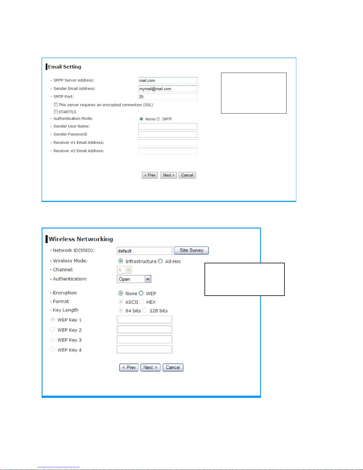
Step 3. Email Settings
Step 4. Wireless Networking (for wireless model)
Enter the required
information to be
able to send email
with image.
Complete the required
settings for wireless
networking.
Page 21
21
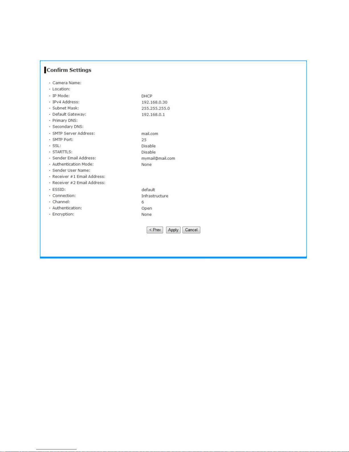
Step 5. Confirm Settings
This step shows the configuration of your camera. When you confirm the settings, click
Apply to finish the wizard and reboot the camera. Otherwise, click Prev to go back to
the previous step(s) and change the settings; or click Cancel to end the wizard and
discard the changes.
Page 22
22
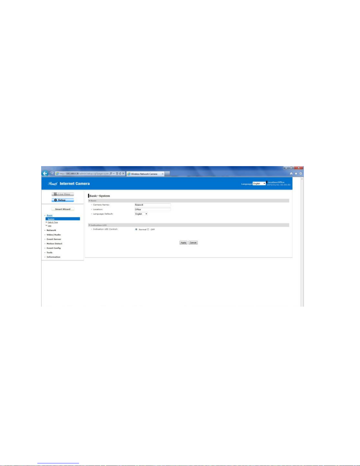
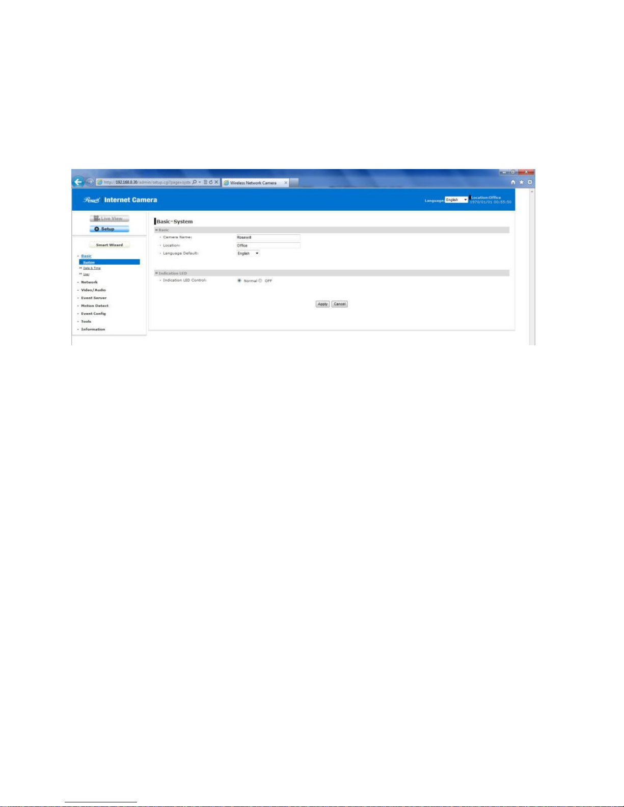
4.3 Basic Setup
The Basic menu contains three sub-menus that provide the system settings for the
camera, such as the Camera Name, Location, Date & Time, and User management.
Basic >> System
Basic
- Camera Name: Enter a descriptive name for the camera.
- Location: Enter a descriptive name for the location used by the camera.
Indication LED
This item allows you to set the LED illumination as desired. There are two options:
Normal and OFF.
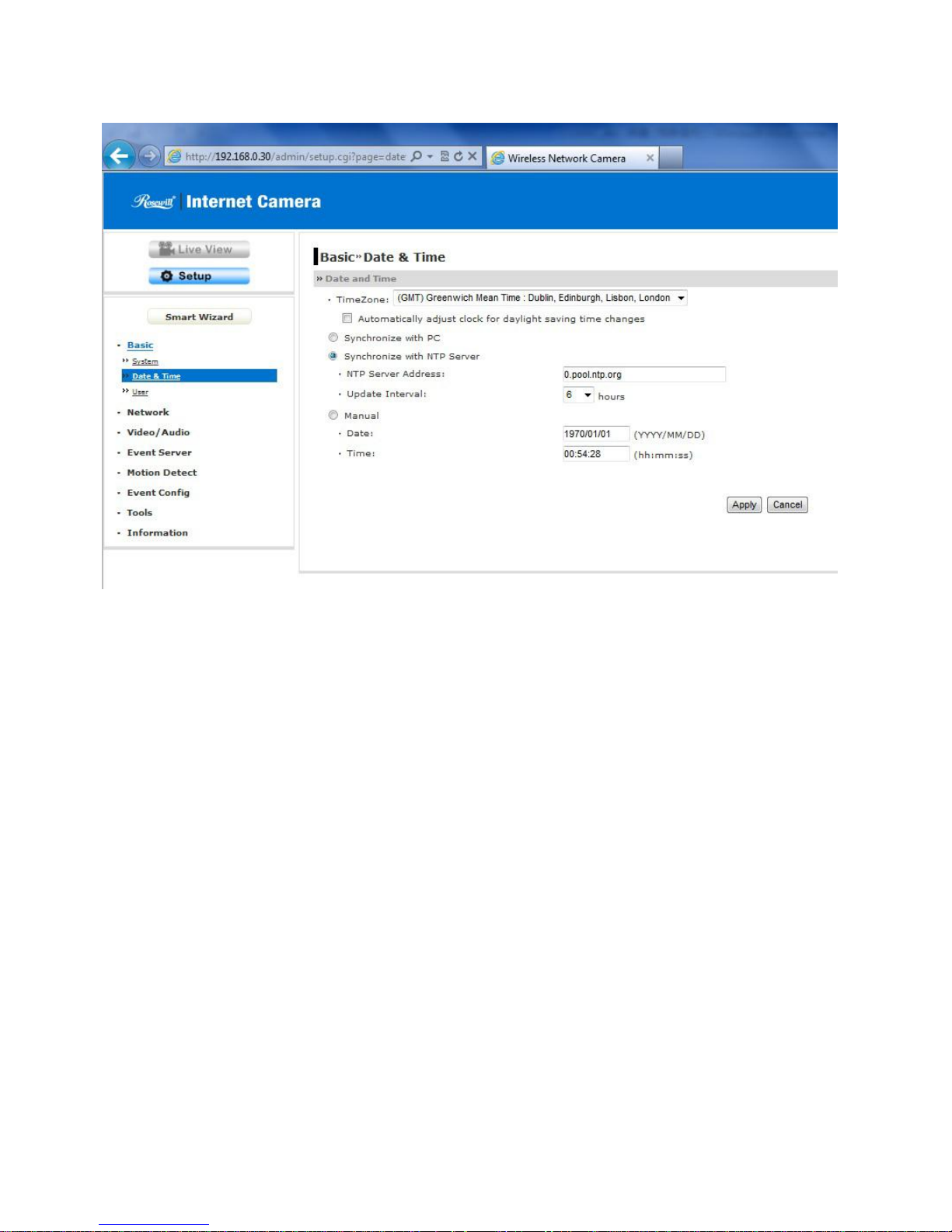
Basic >> Date & Time
Date & Time
- Time Zone: Select the proper time zone for the region from the pull-down menu.
- Synchronize with PC: Select this option and the date & time settings of the
camera will be synchronized with the connected computer.
- Synchronize with NTP Server: Select this option and the time will be
synchronized with the NTP Server. You need to enter the IP address of the
server and select the update interval in the following two boxes.
- Manual: Select this option to set the date and time manually.
Page 23
23
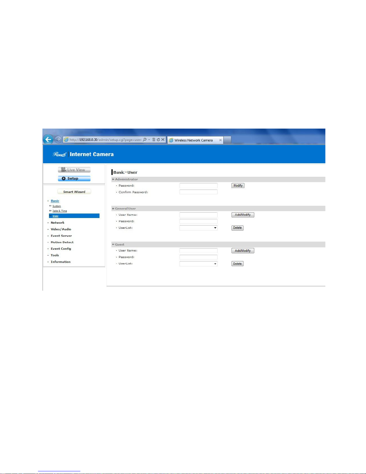
Basic >> User
Administrator
To prevent unauthorized access to the camera’s Web Configuration, you are
strongly recommend to change the default administrator password. Type the
administrator password twice to set and confirm the password.
General User
- User Name: Enter the user’s name you want to add to use the camera.
- Password: Enter the password for the new user.
When you are finished, click Add/Modify to add the new user to the camera. To
modify the user’s information, select the one you want to modify from UserList and
click Add/Modify.
- UserList: Display the existing users of the camera. To delete a user, select the
one you want to delete and click Delete.
Guest
- User Name: Enter the guest’s name you want to add to use the camera.
- Password: Enter the password for the new guest.
Page 24
24
- UserList: Display the existing guests of the camera. To delete a user, select the
one you want to delete and click Delete.
NOTE The “General User” can access the camera and control the Function buttons of
the camera’s Web Configuration; the “Guest’ can only view the live view image
from the main page of the Web Configuration while accessing the camera. Only
the “Administrator” is allowed to configure the camera through the Web
Configuration.
Page 25
25
4.4 Network Settings
The Network menu contains three sub-menus that provide the network settings for the
camera, such as the IP Setting, DDNS Setting, IP Filter, and Wireless (for wireless
model).
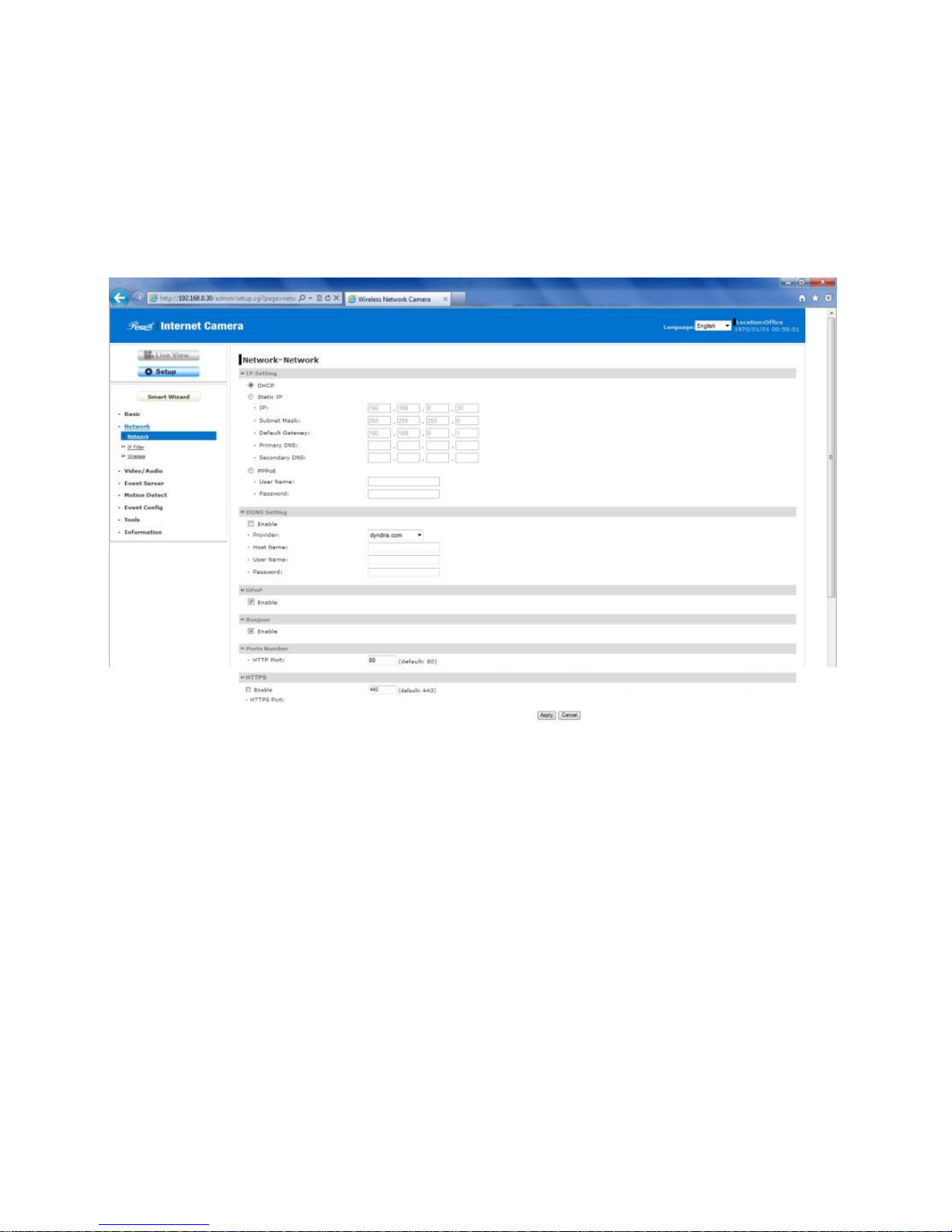
Network >> Network
IP Setting
This item allows you to select the IP address mode and set up the related
configuration.
- DHCP: Select this option when your network uses the DHCP server. When the
camera starts up, it will be assigned an IP address from the DHCP server
automatically.
- Static IP: Select this option to assign the IP address for the camera directly.
You can use IPFinder to obtain the related setting values.
Page 26

26
-
IP
Enter the IP address of the camera. The default
setting is 192.168.0.30.
Subnet Mask
Enter the Subnet Mask of the camera. The default
setting is 255.255.255.0.
Default Gateway
Enter the Default Gateway of the camera. The
default setting is 192.168.0.1.
Primary/
Secondary DNS
DNS (Domain Name System) translates domain
names into IP addresses. Enter the Primary DNS
and Secondary DNS that are provided by ISP.
- PPPoE: Select this option when you use a direct connection via the ADSL
modem. You should have a PPPoE account from your Internet service provider.
Enter the User Name and Password. The camera will get an IP address from
the ISP as starting up.
NOTE Once the camera get an IP address from the ISP as starting up, it automatically
sends a notification email to you. Therefore, when you select PPPoE as your
connecting type, you have to set up the email or DDNS configuration in advance.
DDNS Setting
With the Dynamic DNS feature, you can assign a fixed host and domain name to a
dynamic Internet IP address. Select the Enable option to enable this feature. Then,
select the Provider from the pull-down list and enter the required information in the
Host Name, User Name, and Password boxes. Please note that you have to sign up
for DDNS service with the service provider first.
UPnP
The camera supports UPnP (Universal Plug and Play), which is a set of computer
network protocols that enable the device-to-device interoperability. In addition, it
supports port auto mapping function so that you can access the camera if it is behind
an NAT router or firewall. Select the Enable option to enable this feature.
Ports Number
- HTTP Port: The default HTTP port is 80.
NOTE If the camera is behind an NAT router of firewall, the suggested to be used is
from 1024 to 65535.
Page 27

27
HTTPS
- Enable: Select this option to enable HTTPS, which is a secure protocol to
provide authenticated and encrypted communication within your network.
- HTTPS Port: Assign a HTTPS port in the text box. The default HTTPS port is
443.
Network >> IP Filter
The IP Filter setting allows the administrator of the camera to limit the users within a
certain range of IP addresses to access the camera. To disable this feature, select the
Disable option; otherwise, select the Accept option to assign the range of IP addresses
that are allowed to access the camera, or select the Deny option to assign the range of
IP addresses that are blocked to access the camera.
Disable: Select this option to disable the IP Filter function of the camera.
Accept
- IPv4: Assign a range of IP addresses that are allowed to access the camera by
entering the Start IP address and End IP address options. When you are
finished, click Add to save the range setting. You can repeat the action to assign
multiple ranges for the camera.
- IPv6: Enter the IP Address that is allowed to access the camera.
Deny
- IPv4: Assign a range of IP addresses that are blocked to access the camera by
entering the Start IP address and End IP address options. When you are
finished, click Add to save the range setting. You can repeat the action to assign
multiple ranges for the camera.
- IPv6: Enter the IP Address that is not allowed to access the camera.
For example, when you enter 192.168.0.50/192.168.0.80 in Start/End IP Address of
Accept > IPv4, the user whose IP address located within 192.168.0.50 ~ 192.168.0.80
will be allowed to access the camera. On the other hand, if you enter the IP range in
Start/End IP Address of Deny > IPv4, the user whose IP address located within the
range will not be allowed to access the camera.
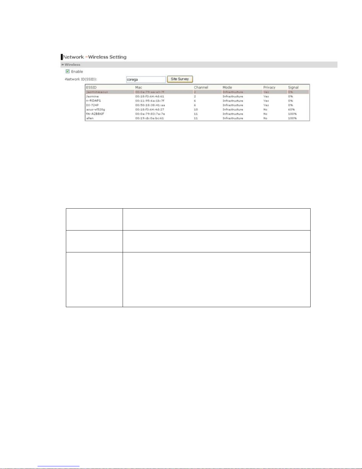
Network >> Wireless Setting (for wireless model)
Page 28
28
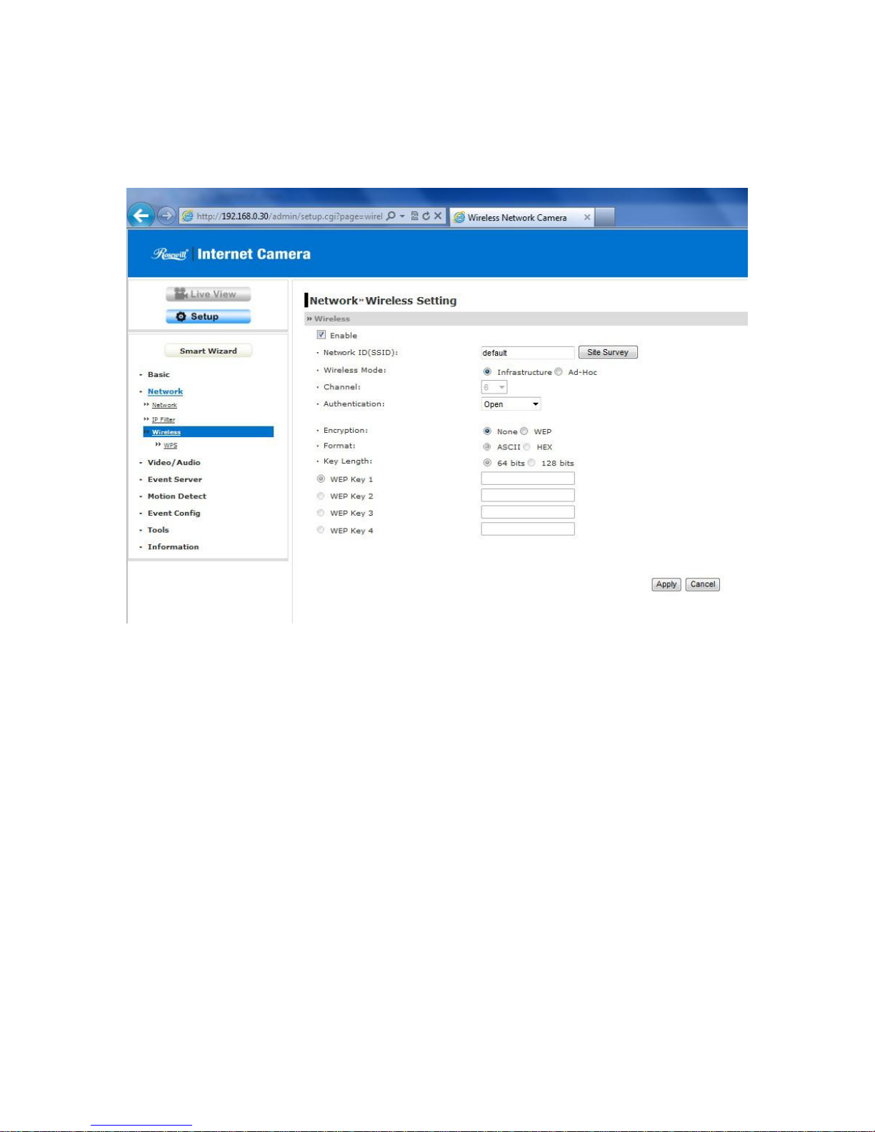
The camera supports WLAN while you use the wireless network. Select the Enable
option to enable this feature.
Wireless
- Network ID (SSID}: Keep the default setting of this option to connect the
camera to any access point under the infrastructure network mode. To connect
the camera to a specified access point, set a SSID for the camera to correspond
with the access point’s ESS-ID. To connect the camera to an Ad-Hoc wireless
workgroup, set the same wireless channel and SSID to match with the
computer’s configuration.
Click Site Survey to display the available wireless networks, so that you can easily
connect to one of the listed wireless networks.
Page 29
29
List of searching results
- Wireless Mode: Select the type of wireless communication for the camera:
Infrastructure or Ad-Hoc.
- Channel: Select the appropriate channel from the list.
- Authentication: Select the authentication method to secure the camera from being
used by unauthorized user: Open, Shared-key, WPA-PSK, and WPA2-PSK. The
following table explains the four options:
Open
The default setting of Authentication mode, which
communicates the key across the network.
Shared-key
Allow communication only with other devices with
identical WEP settings.
WPA-PSK/
WPA2-PSK
WPA-PSK/WPA2-PSK is specially designed for the
users who do not have access to network
authentication servers. The user has to manually enter
the starting password in their access point or gateway,
as well as in each PC on the wireless network.
If you select Open or Shared-key as the Authentication mode, you need to
complete the following settings:
Encryption: Select the WEP option to enable the data encryption feature to
secure the camera within the wireless network.
Format: Once you enable the Encryption feature, you need to determine the
encryption format by selecting ASCII or HEX. ASCII format causes each
character you type to be interpreted as an eight-bit value. Hex format causes
each pair of characters you type to be interpreted as an eight-bit value in
hexadecimal (base 16) notation.
Page 30

30
Key Length: Select the WEP key length you use: 64 bits or 128 bits.
WEP Key 1/2/3/4: Enter the WEP key(s) in the following boxes.
If you select WPA-PSK or WPA2-PSK as the Authentication mode, you need to
complete the following settings:
Encryption: Select TKIP or AES. TKIP (Temporal Key Integrity Protocol)
changes the temporal key every 10,000 packets to insure much greater security
than the standard WEP security. AES (Advanced Encryption Standard) is used to
ensure the highest degree of security and authenticity for digital information.
Pre-Shared Key: This is used to identify each other in the network. Enter the
name in the box, and this name must match the Pre-shared key value in the
remote device.
Page 31

31
Network >> Wireless >> WPS Setting (for wireless model)
WPS (Wi-Fi Protected Setup) sets a new standard of Wi-Fi security, providing a
simplified secure network setup solution for the end users. WPS can be enabled by the
following two options:
1. PIN Mode
2. PBC Mode (or WPS button on the device, depending on hardware design)
PROTECTED SETUP
Press the Reset to Unconfigured button to reset the WPS configuration of the
camera.
WPS
- PIN Mode: The PIN (Personal Information Number) mode builds the connection
by entering the PIN Code directly.
a. Click the PIN Mode option.
b. Click Site Survey button to select the router (or access point) you want to
connect.
c. Click the Connect button to start WPS function of the camera.
d. You need to enter the PIN Code displayed on the camera to the router (or
access point) within 120 seconds to complete the setup.
Page 32

32
- PBC Mode: The PBC (Push-Button-Configuration) mode builds the connection
by simply pressing a button on the device.
a. Click the PBC Mode option.
b. Click the Connect button to start WPS function of the camera.
TIP Instead of clicking the Connect button of Configuration Utility, you can press
the WPS button if the camera is designed with a hardware button of WPS
function.
c. You need to press the WPS button on the router (or access point) within
120 seconds to complete the setup.
Device Status
Display the WPS configuration of the camera.
TIP The Power LED indicates the WPS connection status by:
- blinking 3 times when the connection is built successfully.
- repeating 3 times of short-short-long blink when the connection is failed.
Page 33

33
4.5 Setting up Video & Audio
The Video & Audio menu contains four sub-menus that provide the video and audio
settings for the camera.
Video & Audio >> Camera
Image Setting
- Brightness: Adjust the brightness level from 0 ~ 100.
- Contrast: Adjust the contrast level from 0 ~ 100.
- Saturation: Adjust the colors level from 0 ~ 100.
TIP Click Default then Apply to restore the default settings of the three options
above.
Page 34

34
- Mirror: Select the Horizontal option to mirror the image horizontally. Select the
Vertical option to mirror the image vertically.
- Light Frequency: Select the proper frequency according to the camera’s
location: 50Hz or 60Hz.
Video & Audio >> Video
MJPEG
- Video Resolution: Select the desired video resolution from the three formats:
VGA, QVGA and QQVGA. The higher setting (VGA) obtains better video quality
while it uses more resource within your network.
- Video Quality: Select the desired image quality from five levels: Lowest, Low,
Normal, High, and Highest.
- Frame Rate: Select a proper setting depending on your network status. The
available setting value includes: 5, 10, 15, 20, or 25.
Video & Audio >> Audio
Camera Microphone In:
- Enable: Select the Enable option to enable the camera's audio function, so that
you can receive the on-site sound and voice from the camera.
Page 35

35
4.6 Event Server Configuration
The Event Server menu contains two sub-menus that allow you to upload images to
FTP, and send emails that include still images.
When you complete the required settings for FTP, or Email, click Test to test the related
configuration is correct or not. Once the camera connects to the server successfully,
click Apply.
Event Server Setting>> FTP
FTP
- Host Address: Enter the IP address of the target FTP server.
- Port Number: Enter the port number used for the FTP server.
- User Name: Enter the user name to login into the FTP server.
- Password: Enter the password to login into the FTP server.
- Directory Path: Enter the destination folder for uploading the images. For
example, /Test/.
- Passive Mode: Select the Enable option to enable passive mode.
Page 36

36
Event Server Setting >> Email
Email
- SMTP Server Address: Enter the mail server address. For example, mymail.com.
- Sender Email Address: Enter the email address of the user who will send the
email. For example, John@mymail.com.
- SMTP Port: Assign the SMTP port in the text box. The default SMTP port is 25. If
the mail server requires an encrypted connection, you should check the SSL
option. STARTTTLS is an extension to plain text communication protocols. It
offers a way to upgrade a plain text connection to an encrypted (TLS or SSL)
connection instead of using a separate port for encrypted communication.
- Authentication Mode: Select None or SMTP according to the mail server
configuration.
- Sender User Name: Enter the user name to login the mail server.
- Sender Password: Enter the password to login the mail server.
- Receiver #1 Email Address: Enter the first email address of the user who will
receive the email.
- Receiver #2 Email Address: Enter the second email address of the user who
will receive the email.
- WAN IP Change Notification: Select the option to enable the system to notify
you when the WAN IP address changed.
Page 37

37
4.7 Motion Detect
The Motion Detect menu contains the command and option that allow you to enable and
set up the motion detection feature of the camera. The camera provides two detecting
areas.
To enable the detecting area, select Window 1 or 2 from the pull-down list, and then
select Enable. When the detecting area is enabled, you can use the mouse to move the
detecting area and change the area coverage.
- Name: Assign a name to the detecting area.
- Threshold: Move the slide bar to adjust the level for detecting motion to record
video.
Page 38

38
4.8 Event Configuration
The Event Configuration menu contains four sub-menus that provide the commands to
configure event profiles.
Event Configuration >> General Setting
- Snapshot/Recording Subfolder: You can assign a given sub-folder for
captured file. Otherwise, leave this option blank to use the default setting.
Event Configuration >> Arrange Schedule Profile
This sub-menu displays the scheduled profile(s). To customize the profile, click Add
and then enter a descriptive name for the profile in the prompt dialog window. After
entering the profile name, click OK and the profile is added to the Schedule Profiles list.
To delete the profile, select the profile in the list and click Delete.
Page 39

39
- Profile Name: Display the profile name that you select in the Schedule Profiles
list.
- Weekdays: Select the weekday(s) that you want to separately assign in the
schedule profile. The weekday that has been assigned will be displayed with
green color.
- Time List: Display the time period that you have assigned within the selected
weekday. To assign the same time period to every weekday, click Add this to
all weekdays; click Delete this from all weekdays to remove the selected time
period from every weekday. Click Delete to remove the selected time period.
- Start/End Time: Enter the start and end time and then click Add to assign a
time period within in the selected weekday.
Event Configuration >> Motion Detect Trigger
Select the Enable option to enable the trigger function of the camera, so that you can
send captured images within the detecting area to the FTP server, or email receiver.
You have to configure corresponding settings, such as FTP server and email server, to
enable this feature.
- Schedule Profile: Select a schedule profile from the pull-down list.
- Action: Select the destination that the captured images will be sent to: Send
Email, or FTP Upload.
Page 40

40
Event Configuration >> Schedule Trigger
You can separately configure the schedule for trigger function of the camera by Email,
or FTP. Select the Enable option on each item, and then select a Schedule Profile
from the pull-down list and set the Interval time.
Page 41

41
4.9 Tools
The Tools menu provides the commands that allow you to restart or reset the camera.
You can also backup and restore your configuration, and upgrade the firmware for the
camera.
Factory Reset
Click Reset to restore all factory default settings for the camera.
System Reboot
Click Reboot to restart the camera just like turning the device off and on. The
camera configuration will be retained after rebooting.
Configuration
You can save your camera configuration as a backup file on your computer.
Whenever you want to resume the original settings, you can restore them by
retrieving the backup file.
Page 42

42
- Backup: Click Get the backup file to save the current configuration of the
camera.
- Restore: Click Browse to locate the backup file and then click Restore.
Update Firmware
This item displays the current firmware version. You can upgrade the firmware for
your camera once you obtained a latest version of firmware.
- Select the firmware: Click Browse to locate the backup file and then click
Update.
NOTE Make sure to keep the camera connected to the power source during the
process of upgrading firmware. Otherwise, the camera might be damaged
because of failure of upgrading firmware.
Page 43

43
4.10 Information
The Information menu displays the current configuration and events log of the camera.
Device Info
Display the Basic, Video, Network, and Wireless settings (for wireless model) of the
camera.
System Log
The Logs table displays the events log recorded by the system.
Page 44

44
CHAPTER 5
Software Application - UltraView Pro
5.1 Introduction
This Software User Guide provides detailed instructions on operating UltraView Pro, a
customized software application with a user-friendly interface allowing you to access
and control your camera(s). You can connect up to 32 cameras to monitor different
places and record events for each camera. With UltraView Pro, you can also change
some basic settings of the camera, such as schedule profiles and motion detecting. In
addition, if your camera supports advanced features, such as audio or pan/tilt function,
you can use these functions through the control panels of UltraView Pro.
To use UltraView Pro, you have to install it in your computer. It is recommended to use a
high performance computer if you want to connect multiple cameras simultaneously.
Platform: Microsoft® Windows® XP/Vista*, and Windows 7
Hard Disk: 80GB or above
Resolution: 1024x768 or above
Hardware Requirement
1~8 cameras: Intel Core 2 Duo; 2GB RAM
9~32 cameras: Intel Core 2 Quad; 4GB RAM
* For Windows Vista users: please go to User Accounts and Family Safety > User
Accounts > Turn User Account Control on or off, then uncheck the “Use User Account
Control (UAC) to help protect your computer checkbox. Restart your computer to
validate the setting. For additional information of User Account Control, please go to
http://www.microsoft.com/windows/products/windowsvista/features/details/useraccount
control.mspx
Page 45

45
5.2 Installation
IMPORTANT! Before installing the program, make sure that the Avira AntiVir (the
anti-virus application) is not installed in your computer system.
Otherwise, UltraView Pro might be malfunctioned while operating in
your system.
1. Insert the Installation CD-ROM into the CD drive of your computer to initiate the
Auto-Run program.
The Auto-Run screen provides the following buttons:
- Quick Guide
- Advanced Guide
- Software Manual
- IPFinder
- Install Software
- Browse
- Exit
2. Click Install Software, and the setup wizard appears to help you complete the
installation step-by-step.
NOTE To use UltraView Pro, you must have Microsoft .NET Framework 2.0
installed in the computer. The setup wizard will detect it and, if the program
is not installed yet, ask you to install it during the process of installing
UltraView Pro.
Microsoft Windows Installer 3.0 or above is a required component to install
UltraView Pro. For more information of the required component during
installation, please visit the Microsoft support Website.
3. Click Install. The Install Shield Wizard starts to install UltraView Pro to your
computer.
The Status bar indicates the installation process.
4. When done, click Finish to complete the installation.
You will see the program icon appeared on the desktop of your computer.
Page 46

46
TIP The IPFinder program will be installed in your computer simultaneously when you
install UltraView Pro.
For more information of using IPFinder, refer to Chapter 5 or the User Guide provided
by your camera.
Page 47

47
5.3 Using UltraView Pro
5.3.1 Starting the Program
1. Click Start Programs UltraView Pro UltraView Pro.
Alternatively, you can start the program by double-clicking the program icon on the
desktop of your computer.
2. On the login window, enter the User name/Password and click OK to login.
If this is the first time you start the program and login, use the default User name /
Password: admin / admin.
NOTE For security purpose, you are highly recommended to change the default user
name and password after login. For more information, see the Configuring the
System > User Management section.
Page 48

48
5.3.2 Main Window and Item Feature
When you start and login to UltraView Pro, the Main window will display as below:
The Main window provides you with the information on operating the system, as well as
the control panel such as the Quick Launch buttons, and so on.
NOTE UltraView Pro requires the resolution setting up to 1024 x 768. For best view of
the application, you are recommended to configure the resolution setting to
1024 x 768 or higher; otherwise, it cannot be displayed on the screen when
launching the program.
Page 49

49
Live View Window displays the live video of the connected camera(s).
Quick Launch Buttons are located below the Live View Window, providing you with
the following quick-launch functions:
Button
Function
Click to select Logout or Close UltraView Pro.
Click to select Restore Recording Type, All Continuous
Recording, or Stop All Recording.
Click and then select to display the View Setting window, switch
to the eMap View window, or check the Camera Status.
Click to display the Playback window.
Click to display the Schedule Configuration window.
Click to configure the event settings: Event Server, Address
Book, and Event Trigger.
Click to configure Device Setting and Recording Setting.
Click to set the Account, Language, and System Setting; or
view the Version or the program.
Camera View Mode buttons in this area allow you to switch the camera view mode.
Button
Function
Display the connected camera(s) in single camera view mode.
Display the connected camera(s) in quad view mode.
Display the connected camera(s) in 3 x 3 grid view mode.
Display the connected camera(s) in 13-camera view mode using
a split window. The first camera is displayed as the major view.
Display the connected camera(s) in 17-camera view mode using
a split window. The first camera is displayed as the major view.
Page 50

50
Display the connected camera(s) in N x N grid view mode,
supporting up to 32 cameras.
Display the live view of the selected camera in full screen mode.
Press the ESC key on the PC keyboard to resume the Main
window.
Automatically switch the live view of each connected cameras in
single camera view mode by 30 seconds*. Click once to start
and click again to stop.
* The auto-switch time is set as 30 seconds by default, which
can be changed by clicking the System Setting and
then change the value from the pull-down list of the Auto
Switch time interval option.
System Information displays the system information, including the date and time,
and the available storage space of the system.
Live View Status provides the status of live view mode, including Camera List and
eMap.
Camera List displays the status of the connected cameras. If multiple
cameras are connected, you can switch to the live view of each camera by
simply selecting the camera from the list.
eMap allows you to select the desired camera to the view from the map easily.
Please note that you have to set up the eMap for monitoring in advance.
Camera Control Buttons provides the control buttons that allow you to control the
selected camera.
Button
Function
Talk On/Off. Click to enable/disable the speaker function of
the connected camera. This option is available only in single
camera view mode.
Listen On/Off. Click to enable/disable the microphone
Page 51

51
function of the connected camera. This option is available only
in single camera view mode.
If the connected camera features pan/tilt functions, you can
use this control panel to set the preset positions (up to 8
positions). Once configured, you can move the camera lens to
the desired position quickly.
To set the preset positions, adjust the camera lens to the
desired position using the Navigation buttons, and then select
the position number (1~8) from the Set button.
To move to the preset position, simply select the position
number (1~8) from the Go button.
Navigation Buttons (Left/Right/Up/Down/Home). If the
connected camera features pan/tilt functions, the Navigation
buttons allow you to move the camera lens position. Clicking
the Home (center) button will move the camera lens to the
assigned home position.
/
The Patrol/Stop buttons are used to enable/disable the
swinging function of the camera. Click Patrol to start patrolling
through the preset positions once. Click Stop to stop
patrolling.
Page 52

52
5.3.3 Accessing the Camera
Before you can access the camera, you have to add the camera to the system.
Adding a Camera
1. Click the button and select Device Setting to display the Device Setting
window.
2. Click New.
3. Click Device Search to search the camera(s) within your network.
Page 53

53
4. Click Search to find the IP address of the connected camera(s). When search is
finished, select the camera and click Add.
Page 54

54
5. The information of the camera will be displayed on the window.
Option
Description
Camera Title
You have to assign a descriptive name for the camera.
IP Address
Display the IP address of the camera.
Port
Display the port path of the camera.
Account
Display the user name for accessing the camera.
Password
The password for accessing the camera will not be
displayed.
Stream
Select the stream type as MPEG4, MJPEG, or H.264.
Record
Select Yes or No to set up recording function of the
camera.
Preview
Window
This window allows you to preview the image of the
camera.
NOTE You MUST click Preview to display the image
before clicking Motion detection area and Save
to complete the camera installation; click
Disconnect to stop previewing.
6. When done, click Save and then click OK to return to the Device Setting window.
The added camera will be displayed in the Device List.
Page 55

55
7. Click the “X” button on the Device Setting window to return to the Main window. The
image of the camera will be displayed.
Page 56

56
Editing / Deleting a Camera
Since you have added camera(s) to the system, you can select one to edit or remove.
Click the button and select Device Setting to display the Device Setting window.
1. On the Device Setting window, the connected camera(s) will be displayed in the
Device List.
2. To delete the camera: select the desired one and then click Remove. When
prompted, click Yes and then select OK to confirm deletion.
To change the configuration of the camera: select the desired one and then
click Modify. The Modify Camera window will appear that allows you to change the
configuration of the camera. When completed, click Preview to display the image
before clicking Save and then click OK to return to the Device Setting window.
Viewing Image of the Camera
Page 57

57
Since you have added camera(s) to the system, the image of the selected camera(s)
will be displayed on the Live View Window automatically. You can view a maximum of
32 cameras simultaneously. Additionally, you can select one-camera or other view
mode to display the video from the Camera View Mode buttons.
For example, if you use only one camera, select single camera view mode ( ), and
the Live View Window will display the view as below. You can select the other modes
according to your need.
The Information icon ( ) on the top-right corner of the window provides you with
the options to connect/disconnect the camera, select a camera to be displayed in the
window, capture a still image of the camera live video, or switch to eMap mode. Click
the Information icon to pop up the shortcut menu and select the desired option.
Page 58

58
5.3.4 Recording / Playing Video
You have to assign the target folder for saving the recorded files before recording.
Configuring the Recording Settings
1. Click the button and then select Record Setting.
2. To assign the target folder for saving the recorded files, click the Browse button
next to the Recording Path option, and then select the desired directory.
To change the time of recording, select the desired time setting from the Record
File pull-down menu.
When completed, click Save
Page 59

59
Enabling / Disabling Recording
While you are adding/editing the camera, you can enable the recording function for the
camera by selecting the Record option.
Alternately, you can set all cameras to start/stop recording when you connect multiple
cameras. Click the button and select All Continuous Recording to set all
cameras to start recording, or select Stop All Recording to set all cameras to stop
recording.
Since you have enabled the recording function of the camera, it will automatically start
recording and save the video clips. The recording time of each file is set to 60 seconds
by default.
NOTE The system will automatically delete the oldest files when storage space is
running out.
Page 60

60
Setting up Schedule for Recording
The system features the schedule recording so that you can set up the schedule to
record as you need.
Click the button to display the Schedule Configuration window, which allows you
to configure the recording schedule.
1. Click New, and then enter the Schedule Title.
2. Select the checkboxes below the Schedule Title to set the time to record video.
One checkbox stands for 30 minutes of recording time. You can choose to assign
the single checkbox repeatedly by using Click, or assign a period of time by using
Slide. Alternately, you can quickly select/cancel the checkboxes by clicking Select
All or Delete All.
3. When completed, click Save. The schedule profile will be added to the Schedule
List.
4. To edit the schedule, select the desired schedule profile from the list, and then
change the settings by using the Modify or Remove button.
Page 61

61
Playback the Recording Files
1. Click the button to display the Playback window.
2. On the Playback window, set the conditions for search, such as selecting the
camera and setting the begin/end date and begin/end time. When the search
condition has been set, click Search.
Page 62

62
The search result will be displayed in the Record File list.
3. To playback the video clip, select the desired file and click Play.
NOTE Codec is required for the system to play the video files. If the video clips cannot
be displayed in the Playback window normally, click link on the screen.
Page 63

63
5.4 Configuring UltraView Pro
5.4.1 Configuring the eMap View Setting
Click the button and select View Setting to configure the camera view setting of
eMap mode.
eMap refers to the geography and device scope of the UltraView Pro, which visually
presents the devices in your security system. It uses a background of the area (e.g. a
picture or a map) as the interface for monitoring.
1. On the View Setting window, click New.
Page 64

64
2. Enter the eMap Name.
3. Click Browse to select a Picture File from your computer. The selected picture will
be displayed in the Preview window.
When completed, click Save.
Page 65

65
4. On the following window, you can assign the camera position in the eMap.
Click the Camera Location button to display the Edit window. Select the camera
from the Camera List, and then click the mouse on the desired position of the map.
The camera icon will be displayed on selected position of the map.
Page 66

66
5. When completed, click Save.
6. To view from eMap:
a. Click the button and select eMap View.
b. Select the map from the eMap Name list.
Page 67

67
c. Click the camera icon, the camera window will then pop up to display the
on-the-spot image.
Editing / Deleting the eMap
1. Click the button and select View Setting.
2. To edit the eMap: In the eMap List, select the desired map and click Modify.
The map’s information will be displayed, where you can change the map’s
information and then click Save when completed.
3. To delete the eMap: In the eMap List, select the desired one and click Remove.
The selected map will be removed from the list.
Page 68

68
5.4.2 Configuring the System
User Management
Click the button and select Account to change the administrator password for the
system.
Enter the Current password, and then enter the new password twice (in the Type new
password and Retype password boxes). When completed, click Save.
Page 69

69
5.4.3 Event Configuration
Configuring Event Trigger
Click the button and select Event Trigger to configure the trigger out function of
the camera.
1. On the Event Trigger window, select the desired camera from the Camera List.
2. Do one of the following:
SMTP: Select this option and enter the Subject and Message, the system will
send an email message to the selected user(s) in the Address Book List.
Play Sound: Select this option select a sound file from the computer, so that
the system will alarm by the sound while triggering out.
Page 70

70
eMap Popup: Select this option and select the eMap profile from the
pull-down menu. The camera view of the eMap will be displayed while
triggering out.
Setting up Event Server
Click the button and select Event Server to configure the SMTP server, so that
you can send emails that include still images as notification.
Select the Enable SMTP option to start the email service of the system. When you
enable the service, you have to complete the following settings.
Page 71

71
SMTP Server Address: Enter the mail server address.
For example, mymail.com.
Sender Email Address: Enter the email address of the user who will send the
email. For example, John@mymail.com.
Authentication Mode: Select None or SMTP according to the mail server
configuration.
Sender User Name: Enter the user name to login the mail server.
Sender Password: Enter the password to login the mail server.
Port Number: Enter the port number used for the email server.
When completed, click Save and then select OK. The system will automatically start the
Event Service.
Page 72

72
Sending Notification to the User
Click the button and select Address Book to assign the user to the Address Book
of the camera. The user will receive a real-time notification from the system while
triggering out.
1. On the Address Book window, click New.
2. In the Address Book Information field, enter the Name and Email of the user.
3. When completed, click Save. The user will be displayed in the Address Book List.
4. To edit the user: In the Address Book List, select the desired user and click Modify.
The user’s information will be displayed, where you can change the user’s
information and then click Save when completed.
5. To delete the user: In the Address Book List, select the desired user and click
Remove. The selected user will be removed from the list.
Page 73

73
5.4.4 Changing System Language
Click the button and select language to change the displayed system language.
On the Language screen, select the preferred language (English, Traditional Chinese,
or Simplified Chinese) and click Save.
Page 74

74
5.4.5 Terminating Operation
When you have finished operating, click the button and select Logout to logout
the system or Close to exit the program.
Page 75

75
5.5 Using IPFinder
IPFinder allows you to easily search the device, such as the Internet camera and video
server, within your network.
1. Click Start Programs UltraView Pro IPFinder.
Alternatively, you can start the program by double-clicking the program icon on the
desktop of your computer.
2. Once you get the IP address of the device, launch the Web browser or UltraView
Pro to access your device.
Display the connected
video server(s). Double
click to link the device.
Click About
to get the Version information of IPFinder.
Click
Link to connect the selected device.
Click
Change IP
to modify the IP address of the selected device.
Click
Search to find the IP address of the connected device(s).
Click Exit to close the utility.
Page 76

76
CHAPTER 6
Remote Live View
6.1 Overview
www.c4mi.com is a website which provides the essential functionalities for users to
manage their C4mi‐licensed devices. Users can register, activate, control their devices
and effectively manage accounts through this website. The following user guide will
walk you through the steps you need in order to take full advantage of the functionalities
that the website has to offer.
6.2 Instructions
WEB: C4mi
6.2.1 User Registration
A) Logging In
Log on to www.c4mi.com.
B) First-time
User
If you are a first‐time user, please click on the Register button to register.
C) Registration Information
Enter your email, display name, and password in the pop‐up dialog box.
Page 77

77
3.1.
Enter a working email address. The system will display an error message if you enter an
email address that has already been registered or if you enter an invalid email address.
3.2.
Enter a display name. Your display name can contain a combination of alphabetical and
numerical characters and can be no more than 20‐character long.
3.3.
Enter and re‐enter password. Password can contain alphabetical and numerical
characters and must be at least 6‐chracter long. The length of your password cannot
exceed 20 characters.
Page 78

78
D) Successful Registration
Click on the Register button when you have entered all the required information. The
following webpage will appear to confirm your registration.
Page 79

79
E) Account Activation Confirmation
Check the email which you have provided to C4mi upon registration. You will receive a
system‐generated email message which contains an account activation link. Click on
the activation link and you will be directed to the following webpage which confirms your
account activation.
Page 80

80
6.2.2 Activating Devices
You can activate your device by entering the correct device activation code. Once your
device is successfully activated, you can start viewing the video image generated by
your device.
A) Activating Device
1. Click on the Activate Device button to start the device activation process.
Page 81

81
2.
Click on the Start button. As the following webpage has indicated, enter the device
activation code and click the Next button.
Page 82

82
3.
The system will display the following webpage once the inputted activation code was
correctly entered. The system will display an error message if the activation code field is
left in blank or an invalid activation code is entered.
Page 83

83
6.2.3. My Device
A) Looking Up Devices
● Your device will be automatically added to My Device list once it is successfully
activated.
● Click on any of the device on the device list appeared on the left to view the
real‐time image from the selected device.
● You can control the direction of the camera lens by clicking on ▲, ▼, ◄ or ► buttons.
● Click on the Edit icon next to the camera name to edit the name of the device.
Page 84

84
Click on save to save the modification or click on cancel to cancel the edit process.
Page 85

85
B) Viewing 8Video Images
Click on the button to view up to 8 camera images at a time.
Page 86

86
Click on any of the camera buttons to view a single video image. Click on the page
number to view the desired real‐time video image(s). You can view up to 8 video
images per page and up to 16 from a total of 2 pages.
Page 87

87
Click on the button on the 8‐video webpage to return to My Device webpage.
Page 88

88
C) Upgrading Your IPD
The red flag next to an IPD indicates that an IPD upgrade application is now available.
Click on the red flag icon and the system will display the following dialog box to confirm
your upgrade request.
● Click on the “Yes” button to start the upgrading process. Your IPD status will be offline
while undergoing the upgrading process.
● The device will return to the online status once it has completed the upgrading
process. Click on the “NO” button to cancel the upgrade request.
Page 89

89
6.2.4. Setting Up Accounts
A) Account Information
1. You can update your display name and password by clicking on the Account tab.
2.
● Enter a new display name. Display name can include a combination of alphabetical
and numerical characters.
● Maximum length of your display name is 20 characters.
● The display name field cannot be left in blank; otherwise the system will generate an
error message.
Page 90

90
3. Password can be left in blank. Should you decide to reset your password, you may
include a combination of alphabetical and numerical characters and the length must be
at least 6‐character long. The maximum length of your password is 20 characters.
4. Click on the Update button to complete your account updating process.
6.2.5. Deleting Devices
Click on Delete Device the webpage will display all the devices you are authorized to
view.
Check the box (es) next to the device(s) which you wish to delete. To delete all devices
displayed on the webpage, check the box next to Display Name.
Page 91

91
After checking the box (es) next to the device(s) you wish to delete, click on the Delete
button. The system will pop up a confirmation dialog box. Click on the Delete button to
delete the selected device(s) or click on Cancel to exit the confirmation dialog box.
Page 92

92
APP: EAGLESENSE
6.3 Operating Eaglesense
1. Please find “EagleSense” app from Andriod Google Play or iTune App Store and
download before using.
2. For the first-time user, if you haven’t registered on C4mi, please go to www.c4mi.com.
to register.
3. If you already registered on C4mi, please use the same email address and password
to log in to EagleSense.
Andriod Google Play
Page 93

93
iTune App Store
Page 94

94
6.3.1 Logging In
Open EagleSense application login page. Enter account User ID, password then tap the
Sign in button to log in to the system. (User ID and password are the same as your
registered C4mi account) Tap on HELP on the bottom right hand corner to enter C4mi
website Help link.
Page 95

95
6.3.2 Viewing Videos
A) Start Viewing Videos
On the camera list, tap the camera from which you wish to view the desired image.
Page 96

96
B) Pinch to Zoom
Touch your iPhone screen with two fingers. Close two fingers to zoom in and open two
fingers to zoom out the image you wish to enlarge or shrink. The frame at the bottom left
corner exhibits the displayed area of the image.
Page 97

97
C) Moving Images Around
When the image is in zoom mode, drag the displayed image to your preferred
location. The frame at the bottom left corner exhibits the current image movement.
Page 98

98
D) Stop Viewing Videos
Tap the button at the bottom right corner to exit the video viewing page and return
to the device list page.
Page 99

99
E) Updating Device Information
Tap the icon of the camera to which you wish to update information, and you will be
directed to the device info page. Enter the desired information to update the device info.
Tap the Save button to save the inputted information.
Page 100

100
6.3.3 Viewing Images Generated from Multiple Videos
EagleSense Application allows you to view up to 4 videos on your iPhone and 8 on your
iPad. You will operate iPad the same way you operate your iPhone. The following steps
walk you through the set up process needed in order to view multiple video images from
your iPhone.
A) Viewing 4Video Images
● Tap the Video button at the bottom of your iPhone screen.
● The following 4 video images will appear (The system displays the images from the 4
cameras you previously selected.)
● Tap any of the 4 images and the screen will display the image which you
selected.
 Loading...