

Page 1

P
PERFORMANCE
POWER SUPPLY
PERFORMANCE Series
USER Manual
RP500-2
RP500-2-S
RP550-2
RP550-2-S
Page 2
Page 3
Page 4
PERFORMANCE
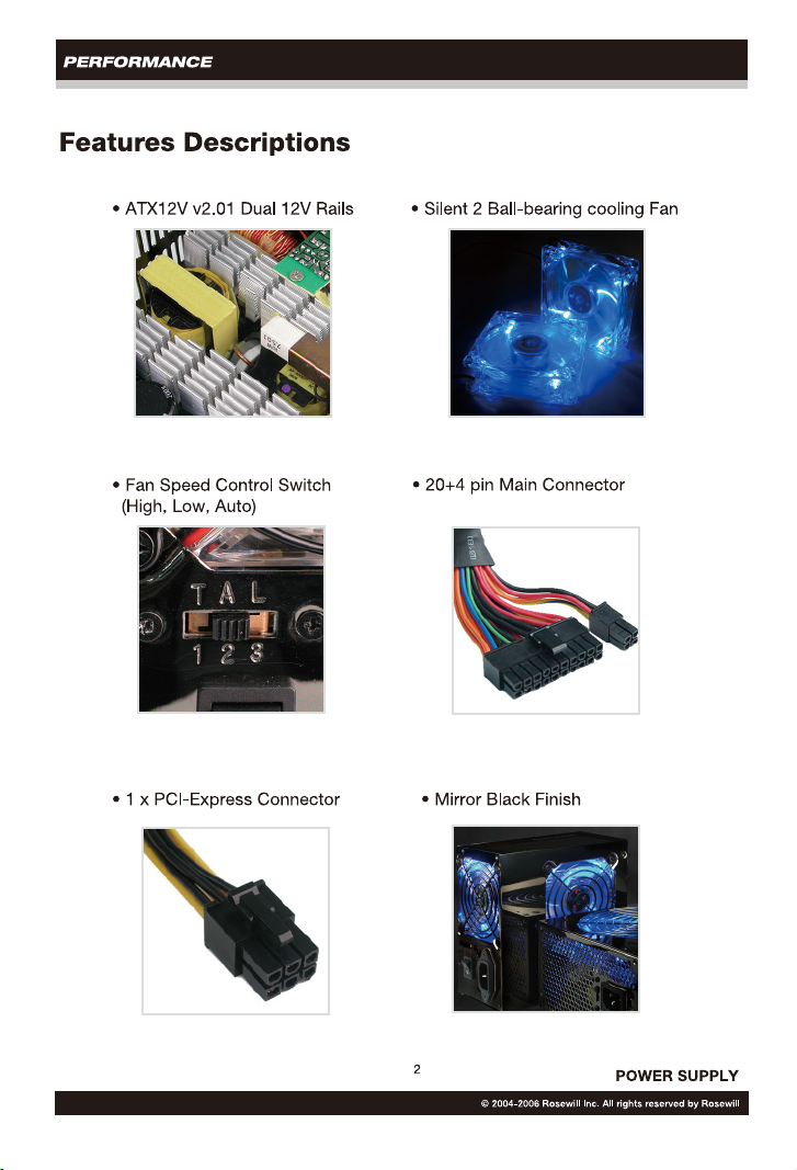
Specification
1. AC Input
RP500-2, RP500-2-S
AC Input Voltage : 115V(100-120V) / 230V(200-240V)
AC Input Frequency : 47 - 63 HZ
AC input Current : 10.0A(RMS) for 115VAC Input, 60Hz
5.5A(RMS) for 230VAC Input, 50Hz
RP550-2, RP550-2-S
AC Input Voltage : 115V(100-120V) / 230V(200-240V)
AC Input Frequency : 47 - 63 HZ
AC input Current : 12A(RMS) for 115VAC Input, 60Hz
6A(RMS) for 230VAC Input, 50Hz
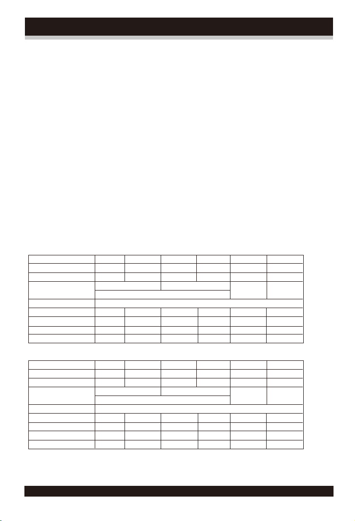
2. DC Output
2.1 Voltage & Current
RP500-2, RP500-2-S
DC OUTPUT +3.3V +5V +12V1 +12V2 -12V +5VSB
MIN.Current 0.5A 0.5A 1.0A 1.0A 0.0A 0.0A
MAX.Current 30A 45A 18A 16A 1.0A 2.5A
Combined Power 275W 380W(31A)
475.5W
Total Power 500W
Regulation ±5% ±5% ±5% ±5% ±10% ±5%
Cross Reg. ±5% ±5% +8%,-5% +8%,-5% ±10% ±5%
Line Reg. ±1% ±1% ±1% ±1% ±2% ±1%
Noise & Ripple (mV) 75 75 120 120 150 75
12.0W 12.5W
RP550-2, RP550-2-S
DC OUTPUT +3.3V +5V +12V1 +12V2 -12V +5VSB
MIN.Current 0.5A 0.5A 1.0A 1.0A 0.0A 0.0A
MAX.Current 30A 50A 18A 18A 1.0A 2.5A
Combined Power 300W 420W(35A)
525.5W
Total Power 550W
Regulation ±5% ±5% ±5% ±5% ±10% ±5%
Cross Reg. ±5% ±5% +8%,-5% +8%,-5% ±10% ±5%
Line Reg. ±1% ±1% ±1% ±1% ±2% ±1%
Noise & Ripple (mV) 75 75 150 150 150 75
3
12.0W 12.5W
POWER SUPPLY
© 2004-2006 Rosewill Inc. All rights reserved by Rosewill
Page 5
PERFORMANCE
2.2 Efficiency
The power supply is a minimum of 72% efficient under typical load. The “Energy Star”
efficiency of the power supply is a minimum of 50% when the AC input power is 60W.
2.3 Remote ON/OFF control
The power supply DC outputs (with the exception of +5 VSB which is always available)
are enabled with an active-low, TTL-compatible signal (“PS-ON”), When PS-ON is
pulled to TTL low, the DC outputs are enabled. When PS-ON is pulled to TTL high or
open-circuited, the DC outputs are disabled. PS-ON may be active by either electronic
means or a mechanical switch.
2.4 Overshoot at TURN-ON/TURN-OFF
The output voltage overshoot upon the application or removal of the input voltage is
less than 10%.
2.5 Hold-up Time
The power supply will maintain output regulation despite a loss of a minimum of 16 ms
while under full load. Test to be performed at nominal input voltage.
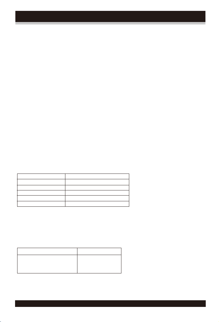
2.6 Power Good Signal
A “power good” signal is asserted by the supply to indicate that the +5VDC output is
within regulation limits.
Power Good Signal Characteristics
Signal Type Open collector TTL compatible
Logic level low <0.8V while sinking 5mA
Logic level high >2.4V while sourcing 500uA
High state impedance 1K (from output to common)
POK delay 100-500ms
Power fall warning time 1ms minimum
3. Protection
3.1 Over Voltage Protection
The power supply prods latch-mode over-voltage protection as defined below:
Nominal output voltage Trigger voltage
+12V 13.4-15.6V
+5V 5.74-7.0V
+3.3V 3.76-4.3V
4
© 2004-2006 Rosewill Inc. All rights reserved by Rosewill
POWER SUPPLY
Page 6

PERFORMANCE
3.2 Short Circuit Protection
A short circuit on any DC output will cause the power to latch. The power supply will
withstand a continuous short circuit to the output without damage or overseers to the
unit. The +5VSB can be shorted indefinitely and will recover automatically when the
short is removed.
3.3 No Load Operation
No hazardous conditions or damage to the supply will occur with all of the DC output
connectors disconnected from the load.
3.4 Over Power Protection(OPP)
The power supply shall go shutdown when the total output load is over 110-160% of
rating.
3.5 Over Current Protection
Overload currents applied to +12V1&+12V2 will cause the output to trip before reaching
or exceeding 240 VA. For testing purposes, the overload currents should be ramped
at a minimum rate of 10 A/s starting from full load.
4. Physical Environment
4.1 Operating Conditions
The power supply shall be capable of continuous operation and meet all electrical
specification without need for adjustment when subjected to the following
environ-mental conditions:
Temp. vs Load Condition Humidity
Operation 0~30
30
40
Storage -20
䎍䎃䎱䏒䎃䏇䏈䏊䏕䏄䏇䏄䏗䏌䏒䏑䎃䏒䏉䎃䏗䏋䏈䎃䏓䏒䏚䏈䏕䎃䏖䏘䏓䏓䏏䏜䎃䏖䏋䏄䏏䏏䎃䏒䏆䏆䏘䏕䎃䏇䏘䏕䏌䏑䏊䎃䏖䏋䏌䏓䏓䏌䏑䏊䎃䏒䏕䎃䏖䏗䏒䏕䏄䏊䏈䎃䏄䏗䎃䏗䏋䏈䎃䏖䏓䏈䏆䏌䏉䏌䏈䏇䎃䏆䏒䏑䏇䏌䏗䏌䏒䏑䎑䎃
4.2 Shocks & Vibration
The power supply will withstand the following imposed conditions without experiencing
non-recoverable failure or deviation form specified output characteristics.
Storage -40G, 11mSec. half-sine wave pulse in both directions on three mutually
perpendicular axes. Operating -10G, 11mSec. half-sine wave pulse in both directions
on three mutually perpendicular axes. Vibration Operation-Sine wave excited, 0.25G
maximum acceleration, 10-250 Hz, swept at one octave/mine. Fifteen-minaret dwell at
all frequencies at which the device under test experience excursions two times large
than non-resonant excursions.
䛐@Full Load
䛐-40䛐@90% Rated Load
䛐-50䛐@80% Rated Load
䛐~80䛐
10䎈~90䎈RH
5䎈~90䎈䎵H
5
© 2004-2006 Rosewill Inc. All rights reserved by Rosewill
POWER SUPPLY
Page 7

PERFORMANCE
5. Regulatory Compliance
5.1 Safety Requirement
-CSA
-UL
-TUV
-FCC CLASS B
5.2 Dielectric Strength
Primary to Secondary: 1500 VAC for 1~3 seconds.
Primary to Frame Ground: 1500 VAC for 1~3 seconds.
5.3 Insulation Resistance
Primary to Secondary: 20 Meg. ohm Minimum.
Primary to Frame Ground: 20 Meg. ohm Minimum.
5.4 Ground Leakage Current
The power supply ground leakage current shall be less than 3.5mA.
5.5 Ground Continuity
The power supply grounding continuity shall be less than 100m when the test
current is at 25A.
5.6 Reliability
The power supply have a minimum predicted MTBF(MIL-STD-217E) of 100,000
hours of conditions operation at 25䛐, maximum-output load, and nominal AC
input voltage.
6
© 2004-2006 Rosewill Inc. All rights reserved by Rosewill
POWER SUPPLY
Page 8

PERFORMANCE
Connectors
• 20+4 pin Main Connector x 1 • 4 pin ATX +12V Connector x 1
• 8 pin EPS +12V Connector x 1 • 6 pin PCI-Express Connector x 1
• 4 pin Peripheral Connector X 8 • 5 pin SATA Connector x 2
• 4 pin Floppy Connector x 2
7
© 2004-2006 Rosewill Inc. All rights reserved by Rosewill
POWER SUPPLY
Page 9

PERFORMANCE
Installation
1. Installing Power Supply
Affix the power supply to the case with screws.
2. 20+4 pin Main Connector
NOTE : 1. Confirm 20 pin or 24 pin main connector your motherboard needs before
the installation.
2. 4 pin here is used for switching between 20 & 24 pin only.
Take the 20 pin connector.
20 pin
Plug the 20 pin connector onto
the motherboard.
8
© 2004-2006 Rosewill Inc. All rights reserved by Rosewill
POWER SUPPLY
Page 10

PERFORMANCE
24 pin
Take the 24 pin connector
Plug the 20 pin part onto the motherboard
Plug the 4 pin part onto the motherboard
NOTE : You can also hold 20 pin and 4 pin connectors together then
plug them into the 24 pin socket
9
© 2004-2006 Rosewill Inc. All rights reserved by Rosewill
POWER SUPPLY
Page 11

PERFORMANCE
3. 4 pin ATX +12V or 8 pin EPS +12V Connector
NOTE :
1. The 4 pin ATX +12V connector or 8 pin EPS +12V connector is used for motherboard.
2. Confirm 4 pin ATX +12V or 8 pin EPS +12V connector your motherboard needs before the installation.
4 pin ATX +12V connector
8 pin EPS +12V connector
4. 6 pin PCI-Express Connector.
The 6 pin PCI-Express connector
used for video card only.
NOTE : Confirm if your video card needing the 6 pin PCI-Express connector or not before the
installation. Not every video card needs it.
6. 4 pin Floppy Connector
The 4 pin Floppy connector used
for Floppy disk or Zip drives.
5. 4 pin Peripheral Connector
The 4 pin Peripheral connector used for HDD,
Optical Drive and other devices needing it.
7. 5 pin SATA Connector
5 pin SATA connector used for SATA HDD
and Optical Drive.
10
© 2004-2006 Rosewill Inc. All rights reserved by Rosewill
POWER SUPPLY
Page 12

PERFORMANCE
8. Before starting your system
• Select the proper voltage setting.
(US = 115V)
• Attach the power cord to the power supply
• Connect the power cord to a power
• Confirm the power supply is on
source.
• Select the Fan Speed setting.
ON OFF
1=T= Fastest Speed (Great cooling but noisy)
2=A= Auto Control (Recommended)
3=L= Slowest Speed (Silent but bad cooling, NOT recommended)
NOTE : Slowest Fan Speed may make the power supply & your system UN-stable.
11
© 2004-2006 Rosewill Inc. All rights reserved by Rosewill
POWER SUPPLY
Page 13

Page 14

 Loading...