

Page 1
RNWD‐N9003PCE
DualBandWirelessPCIEAdapter
UserManual
Page 2

Fwcn"Dcpf"Yktgnguu"REK/G"Cfcrvgt"""""""""""""""""/"RNWD-N9003PCE/"""""""""""""""""""""""""""""""""Wugt‚u"Ocpwcn"
Eqpvgpvu"
Rcemcig"Eqpvgpvu000000000000000000000000000000000000000000000000000000000000000000000000000000000000000000000000000000000000000000004
Ejcrvgt"3"Kpvtqfwevkqp 0000000000000000000000000000000000000000000000000000000000000000000000000000000000000000000000000000000000005
303"Mg{"Hgcvwtgu0000000000000000000000000000000000000000000000000000000000000000000000000000000000000000000000000000 5
304"NGF"Uvcvwu 0000000000000000000000000000000000000000000000000000000000000000000000000000000000000000000000000000000 6
Ejcrvgt"4"Kpuvcnncvkqp"Iwkfg 0000000000000000000000000000000000000000000000000000000000000000000000000000000000000000000000000007
403"Jctfyctg"Kpuvcnncvkqp00000000000000000000000000000000000000000000000000000000000000000000000000000000000000 7
404"Uqhvyctg"Kpuvcnncvkqp 000000000000000000000000000000000000000000000000000000000000000000000000000000000000000 8
40403"Hqt"Ykpfqyu"ZR 000000000000000000000000000000000000000000000000000000000000000000000000000000000000000000008
40404"Hqt"Ykpfqyu"XKUVC 00000000000000000000000000000000000000000000000000000000000000000000000000000000000033
40405"Hqt"Ykpfqyu"9 00000000000000000000000000000000000000000000000000000000000000000000000000000000000000000000036
Ejcrvgt"5"Eqphkiwtcvkqp"Iwkfg00000000000000000000000000000000000000000000000000000000000000000000000000000000000000000000039
503"Hqt"Ykpfqyu"ZR00000000000000000000000000000000000000000000000000000000000000000000000000000000000000000000 39
50303"Ewttgpv"Uvcvwu000000000000000000000000000000000000000000000000000000000000000000000000000000000000000000000039
50304"Rtqhkng"Ocpcigogpv 0000000000000000000000000000000000000000000000000000000000000000000000000000000000003;
50305"Fkcipquvkeu 000000000000000000000000000000000000000000000000000000000000000000000000000000000000000000000000004;
504"Hqt"Ykpfqyu"Xkuvc 0000000000000000000000000000000000000000000000000000000000000000000000000000000000000000 52
505"Hqt"Ykpfqyu"900000000000000000000000000000000000000000000000000000000000000000000000000000000000000000000000 55
Ejcrvgt"6"YRU"Eqphkiwtcvkqp0000000000000000000000000000000000000000000000000000000000000000000000000000000000000000000000057
603"RDE"*Rwuj"Dwvvqp"Eqphkiwtcvkqp+"ogvjqf 0000000000000000000000000000000000000000000000000 58
604"RKP"ogvjqf 0000000000000000000000000000000000000000000000000000000000000000000000000000000000000000000000000000 5:
60403"Gpvgt"c"RKP"kpvq"{qwt"CR"fgxkeg000000000000000000000000000000000000000000000000000000000000000005:
60404"Gpvgt"vjg"RKP"htqo"{qwt"CR"fgxkeg0000000000000000000000000000000000000000000000000000000000005;
Crrgpfkz"C<"HCS0000000000000000000000000000000000000000000000000000000000000000000000000000000000000000000000000000000000000000000062
Crrgpfkz"D<"Eqphkiwtkpi"vjg"RE00000000000000000000000000000000000000000000000000000000000000000000000000000000000000000069
Crrgpfkz"E<"Urgekhkecvkqpu 0000000000000000000000000000000000000000000000000000000000000000000000000000000000000000000000000073
-1-
Page 3

Fwcn"Dcpf"Yktgnguu"REK/G"Cfcrvgt"""""""""""""""""/"RNWD-N9003PCE/"""""""""""""""""""""""""""""""""Wugt‚u"Ocpwcn"
Rcemcig"Eqpvgpvu"
The following items should be found in your package:
1x Rosewill RNWD-N9003PCE (P;22REG) Dual-Band Wireless PCI-E
Adapter
Quick Installation Guide
1x Resource CD for P;22REG, including:
Rosewill Wireless N Utility and Drivers
Wi-Fi Protected Setup (WPS) program
User Guide
Other Helpful Information
Pqvg<"
"
Make sure that the package contains the above items. If any of the listed items are damaged
or missing, please contact with your distributor.
-2-
Page 4

Fwcn"Dcpf"Yktgnguu"REK/G"Cfcrvgt"""""""""""""""""/"RNWD-N9003PCE/"""""""""""""""""""""""""""""""""Wugt‚u"Ocpwcn"
Ejcrvgt"3"Kpvtqfwevkqp"
This Dual Band Wireless PCI-E adapter is designed to provide a high-speed and
ultimate wireless performance for your PC. With a fast wireless connection, you
can get a better Internet experience, such as downloading, gaming, video
streaming and etc.
The N900PCE’s auto-sensing capability allows high packet transfer rate up to
450Mbps for maximum throughput on 2.4GHz or 5GHz. With the unique design
features, N900PCE has good capability on anti-jamming; and can interoperate
with other wireless (802.11a/b/g/n) products. The adapter supports WEP, WPA
and WPA2 encryption to prevent outside intrusion and protect your personal
information from being exposed.
The Quick Setup Wizard guides you step-by-step through the installation process;
the Wireless N Utility helps you create a wireless connection immediately.
With unmatched wireless performance, reception, and security protection, the
N900PCE can be your best choice for easily adding or upgrading wireless
connectivity.
303"Mg{"Hgcvwtgu"
Fwcn"Dcpf"Uwrrqtv"
Dual Band is the wireless technology which allowing the adapter to
connect with a 2.4GHz or 5GHz network. This allows you to check e-mail
and browse the Internet using the 2.4GHz band or stream HD movies
and other media on the 5GHz band. The advantage of working on the
5GHz band is that, unlike the crowded 2.4GHz band shared with
microwaves, cordless phones and other wireless networks, it has much
less interference and can provide a more stable wireless signal, which is
ideal for online gaming and HD video streaming.
-3-
Page 5

Fwcn"Dcpf"Yktgnguu"REK/G"Cfcrvgt"""""""""""""""""/"RNWD-N9003PCE/"""""""""""""""""""""""""""""""""Wugt‚u"Ocpwcn"
Yktgnguu/P"Urggf"wr"vq"672Odru"
Both the adapter’s 2.4GHz and 5GHz bands support the maximum
speed of up to 450Mbps, which generates a maximum theoretical
wireless throughput bringing you a limitless wireless experience.
Cfxcpegf"Ugewtkv{"
WPA/WPA2 encryption standards ensure your wireless connection is
safe from intruders."
304"NGF"Uvcvwu"
Uvcvwu Yqtmkpi"Uvcvwu"
Off The driver has not been installed."
The driver has been installed but there is no data being
Flashing Slowly "
transmitted or received."
Flashing Quickly " There is data being transmitted or received."
-4-
Page 6
Fwcn"Dcpf"Yktgnguu"REK/G"Cfcrvgt"""""""""""""""""/"RNWD-N9003PCE/"""""""""""""""""""""""""""""""""Wugt‚u"Ocpwcn"
Ejcrvgt"4"Kpuvcnncvkqp"Iwkfg"
Please install the PCI-E adapter into your computer before installing the driver
software from the Resource CD.
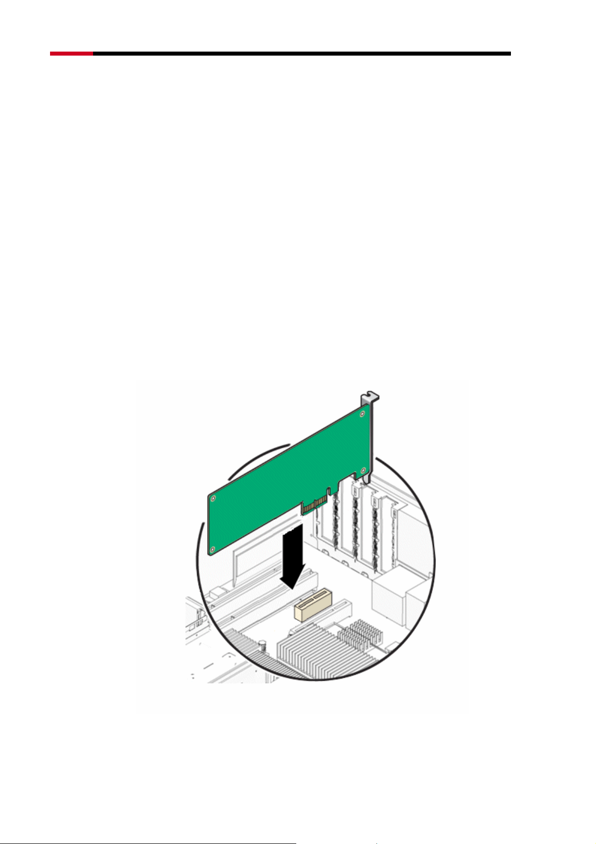
403"Jctfyctg"Kpuvcnncvkqp"
1. Turn off your computer and unplug the power cord from the computer.
2. Open the case and locate an available PCI-E slot. Remove the metal slot
cover on the back of the PC. Keep the screws. Turn to your computer
manufacturer for instructions if needed.
3. Insert the PCI-E adapter into the PCI-E slot. Make sure that all of its pins
have touched the slot's contacts. Once the adapter has been firmly inserted,
screw its fastening tab. Then, close your PC case.
4. Insert the power cable back into the computer and turn on your computer.
"
-5-
Page 7
Fwcn"Dcpf"Yktgnguu"REK/G"Cfcrvgt"""""""""""""""""/"RNWD-N9003PCE/"""""""""""""""""""""""""""""""""Wugt‚u"Ocpwcn"
Pqvg<"
"
The promoted Found New Hardware Wizard screen will pop up when the adapter is installed
correctly. Click Ecpegn.
404"Uqhvyctg"Kpuvcnncvkqp"
40403"Hqt"Ykpfqyu"ZR"
The adapter’s Setup Wizard will guide you through the installation procedures for
Windows 7, Windows Vista, and Windows XP. The procedures in different
systems are quite similar, therefore here takes the procedures in Windows XP for
example.
1. Insert the Resource CD into your CD-ROM drive. To continue, double-click
O{" Eqorwvgt, and then double-click the EF1FXF drive where the
installation CD was placed. Open P;22REG folder, and double-click"
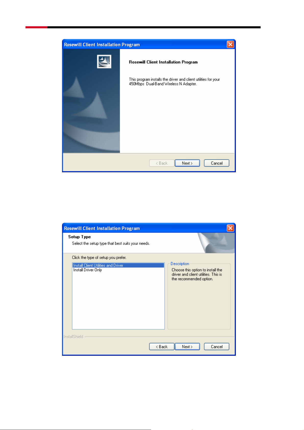
Ugvwr0gzg. Then you will see Figure 0-1.
Figure 0-1
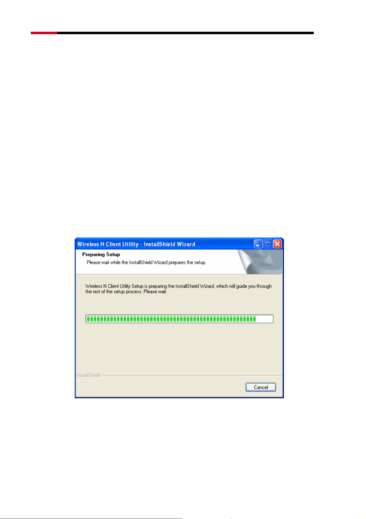
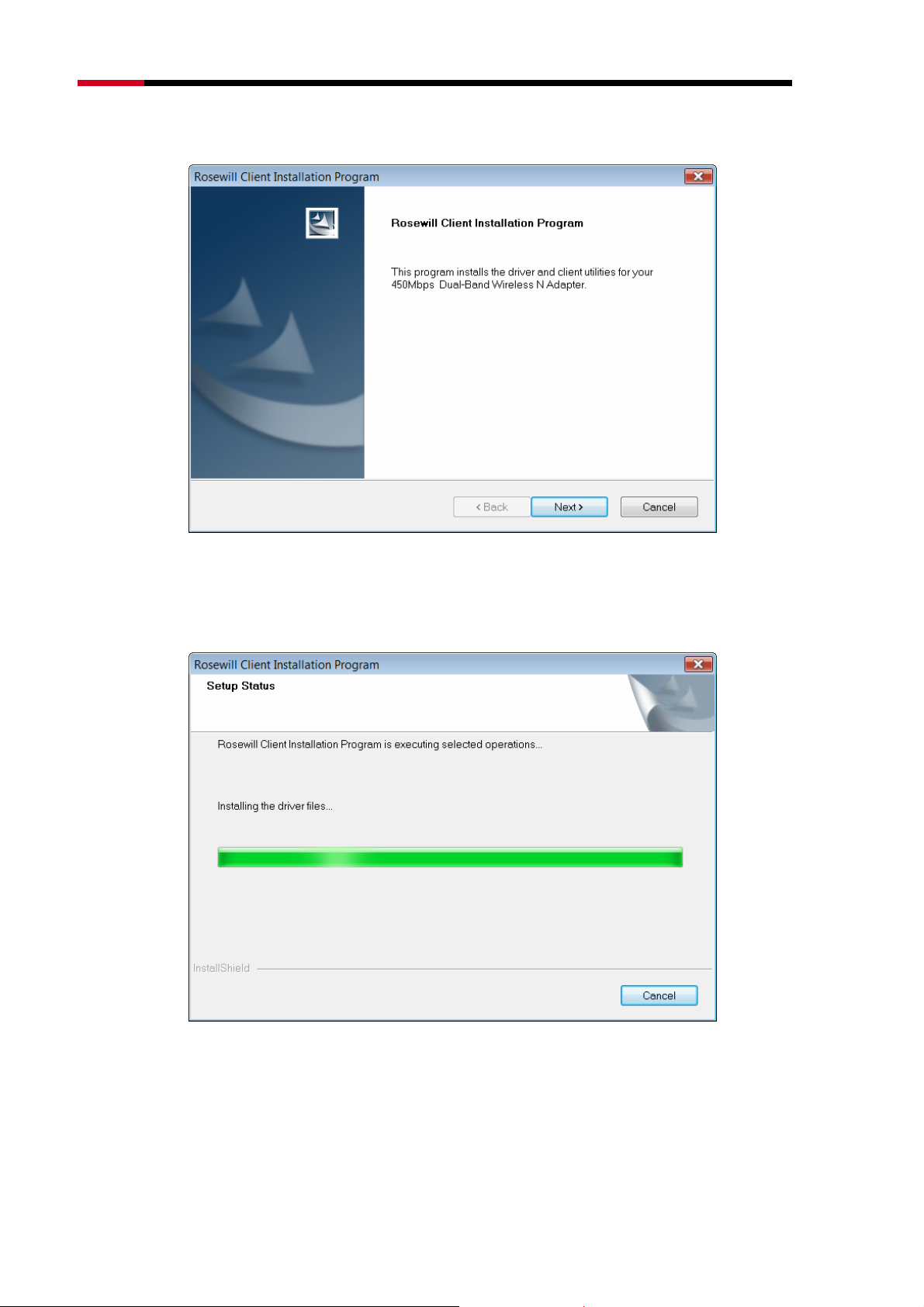
2. Soon, XFigure 0-2 will display after a moment. Click Pgzv to continue.
-6-
Page 8
Fwcn"Dcpf"Yktgnguu"REK/G"Cfcrvgt"""""""""""""""""/"RNWD-N9003PCE/"""""""""""""""""""""""""""""""""Wugt‚u"Ocpwcn"
Figure 0-2
3. After that, you should choose a Setup type. It is recommended that you
select Kpuvcnn"Enkgpv"Wvknkvkgu"cpf"Ftkxgt. Select Kpuvcnn"Ftkxgt"Qpn{ to install
driver only (shown in XFigure 0-3). Click Pgzv to continue.
Figure 0-3
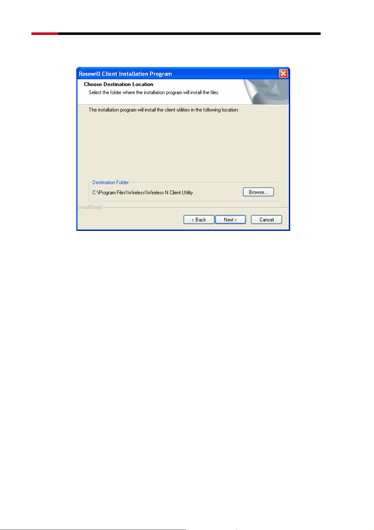
4. Click Dtqyug” to change the destination location for the software, then click
-7-
Page 9
Fwcn"Dcpf"Yktgnguu"REK/G"Cfcrvgt"""""""""""""""""/"RNWD-N9003PCE/"""""""""""""""""""""""""""""""""Wugt‚u"Ocpwcn"
Pgzv"in the screen below (shown in Figure 0-4).
Figure 0-4
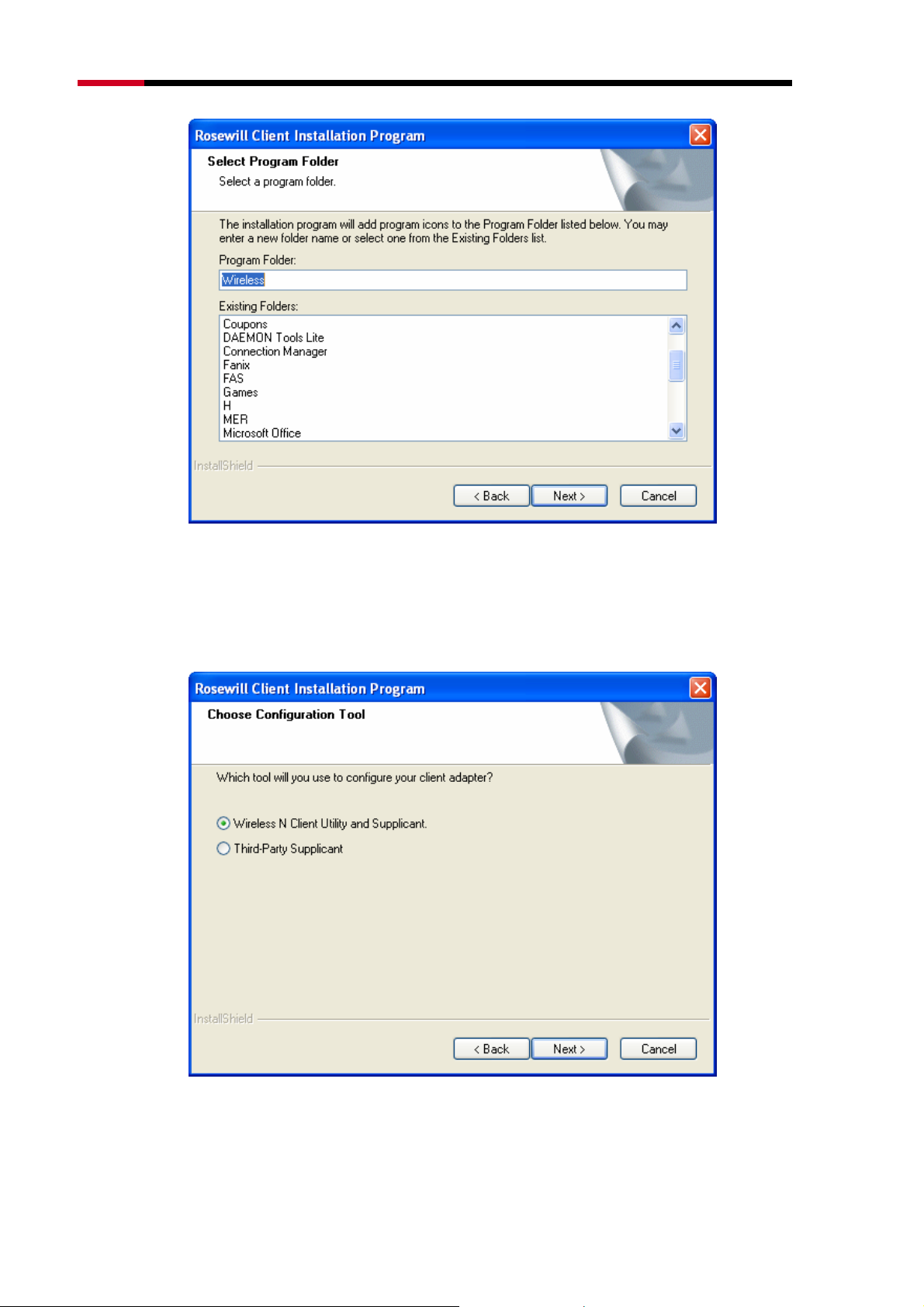
5. After that, select the program folder, you should create a new folder name or
select one from the Gzkuvkpi"Hqnfgtu list. It is recommended that you keep
the default setting. Click Pgzv to continue the installation.
-8-
Page 10
Fwcn"Dcpf"Yktgnguu"REK/G"Cfcrvgt"""""""""""""""""/"RNWD-N9003PCE/"""""""""""""""""""""""""""""""""Wugt‚u"Ocpwcn"
Figure 0-5
6. Choose configuration tool, if you are not sure, please leave it default. Then
click Pgzv to continue.
Figure 0-6
"
-9-
Page 11
Fwcn"Dcpf"Yktgnguu"REK/G"Cfcrvgt"""""""""""""""""/"RNWD-N9003PCE/"""""""""""""""""""""""""""""""""Wugt‚u"Ocpwcn"
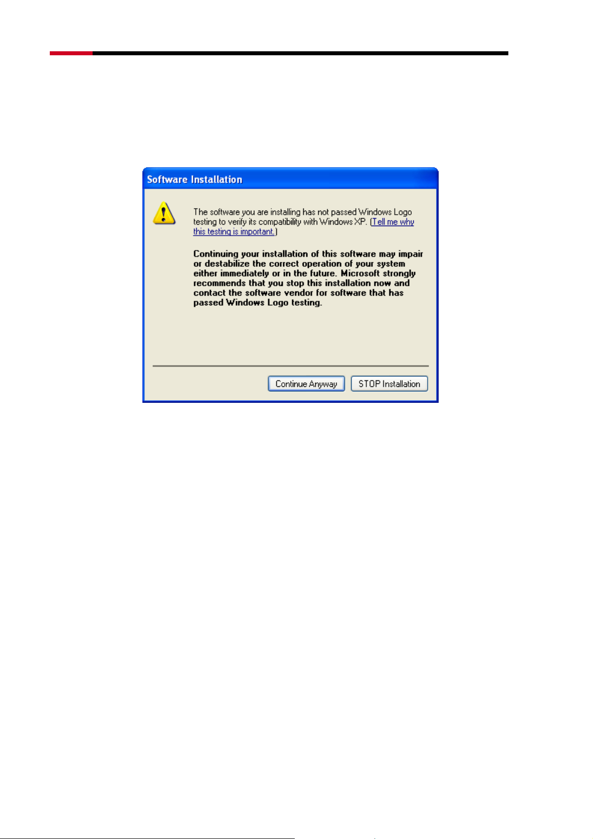
Pqvg<"
"
For Windows XP, the Setup Wizard will notify you of how to proceed with the installation
during these steps (shown in
able to work with the operating system. Click Eqpvkpwg"Cp{yc{ to continue the Installation.
XFigure 0-7). Our drivers have been tested thoroughly, and are
Figure 0-7
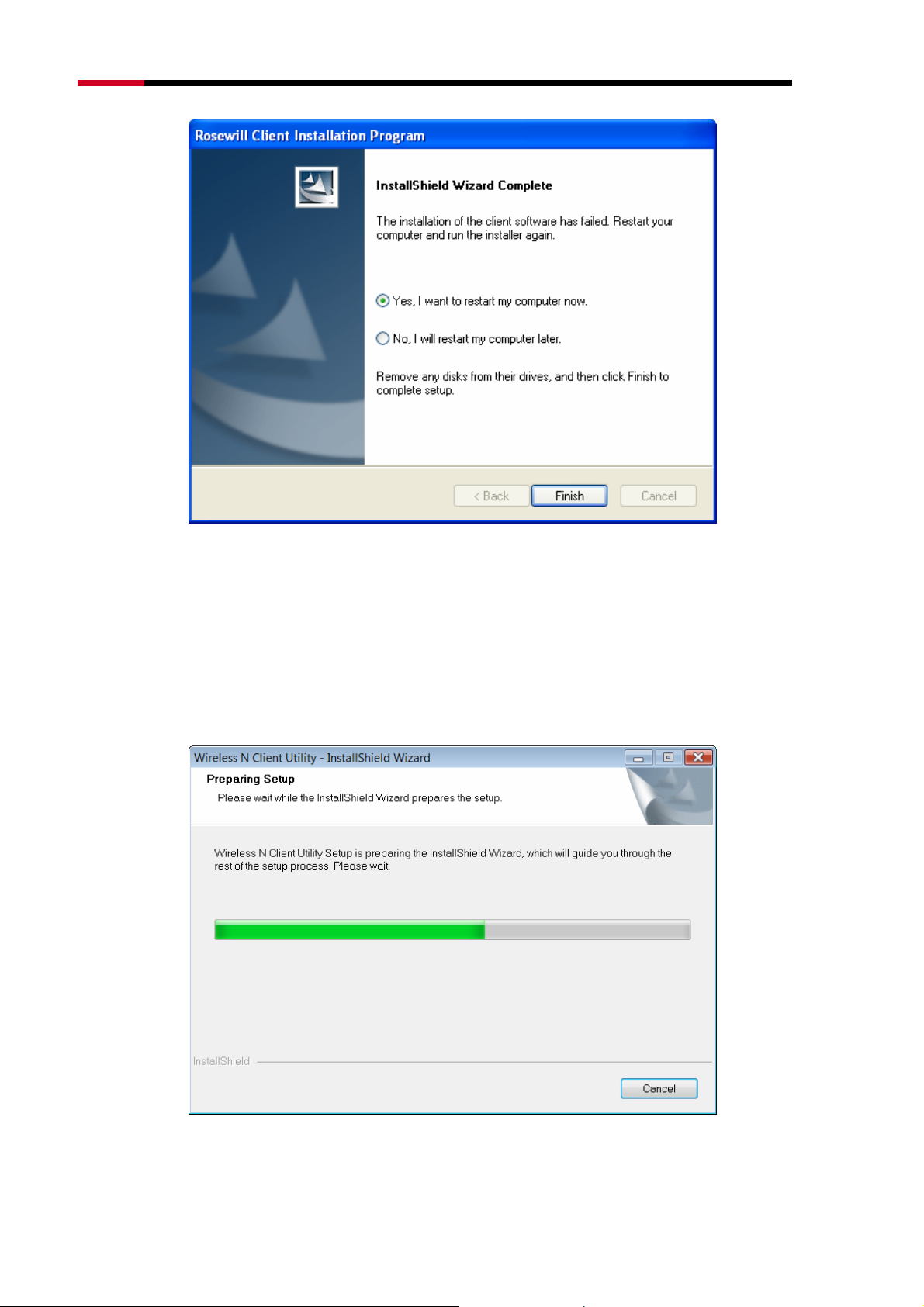
7. After all the steps above, you will see the screen below, click Hkpkuj to reboot
the system.
-10-
Page 12
Fwcn"Dcpf"Yktgnguu"REK/G"Cfcrvgt"""""""""""""""""/"RNWD-N9003PCE/"""""""""""""""""""""""""""""""""Wugt‚u"Ocpwcn"
Figure 0-8
40404"Hqt"Ykpfqyu"XKUVC"
1. Insert the Resource CD into your CD-ROM drive. To continue, find the
CD/DVD drive where the installation CD was placed. Open P;22REG folder,
and double-click Ugvwr0gzg. Then you will see Figure 0-9.
Figure 0-9
-11-
Page 13
Fwcn"Dcpf"Yktgnguu"REK/G"Cfcrvgt"""""""""""""""""/"RNWD-N9003PCE/"""""""""""""""""""""""""""""""""Wugt‚u"Ocpwcn"
2. Soon, Figure 0-10 will display after a moment. Click Pgzv to continue.
Figure 0-10
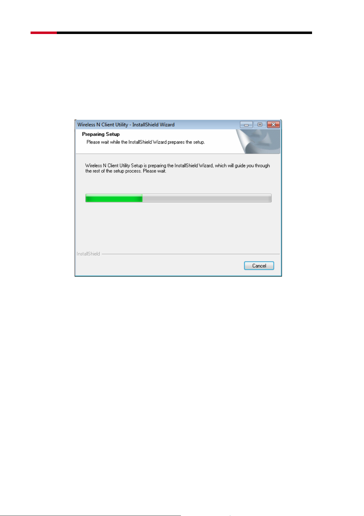
3. Wait a while for the setup as shown in Figure 0-11.
Figure 0-11
"
"
-12-
Page 14
Fwcn"Dcpf"Yktgnguu"REK/G"Cfcrvgt"""""""""""""""""/"RNWD-N9003PCE/"""""""""""""""""""""""""""""""""Wugt‚u"Ocpwcn"
Pqvg<"
"
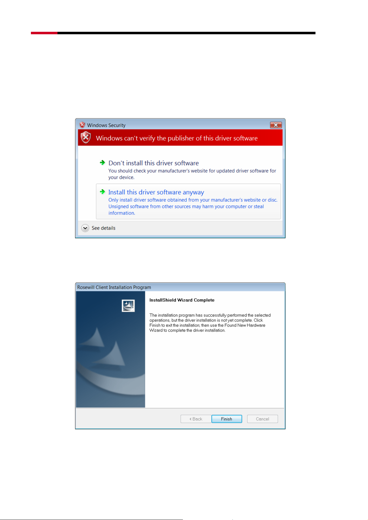
For Windows Vista, the Setup Wizard will notify you about the Windows Security with the
installation during these steps (shown in
thoroughly, and are able to work with the operating system. Click Kpuvcnn" vjku" ftkxgt"
uqhvyctg"cp{yc{ to continue the Installation.
XFigure 0-12). Our drivers have been tested
Figure 0-12
4. Then you will see Figure 0-13. Click Hkpkuj to complete.
Figure 0-13
-13-
Page 15
Fwcn"Dcpf"Yktgnguu"REK/G"Cfcrvgt"""""""""""""""""/"RNWD-N9003PCE/"""""""""""""""""""""""""""""""""Wugt‚u"Ocpwcn"
40405"Hqt"Ykpfqyu"9"
1. Insert the Resource CD into your CD-ROM drive. To continue, find the
CD/DVD drive where the installation CD was placed. Open P;22REG folder,
and double-click Ugvwr0gzg. Then you will see Figure 0-14.
Figure 0-14
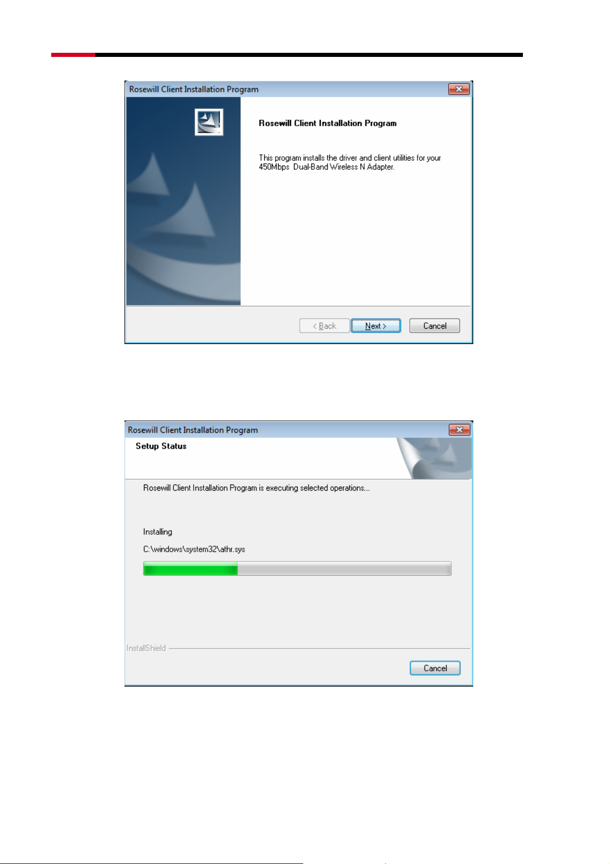
2. Soon, Figure 0-15 will display after a moment. Click Pgzv to continue.
-14-
Page 16
Fwcn"Dcpf"Yktgnguu"REK/G"Cfcrvgt"""""""""""""""""/"RNWD-N9003PCE/"""""""""""""""""""""""""""""""""Wugt‚u"Ocpwcn"
Figure 0-15
3. Wait a while for the setup as shown in Figure 0-16.
Figure 0-16
"
-15-
Page 17
Fwcn"Dcpf"Yktgnguu"REK/G"Cfcrvgt"""""""""""""""""/"RNWD-N9003PCE/"""""""""""""""""""""""""""""""""Wugt‚u"Ocpwcn"
Pqvg<"
"
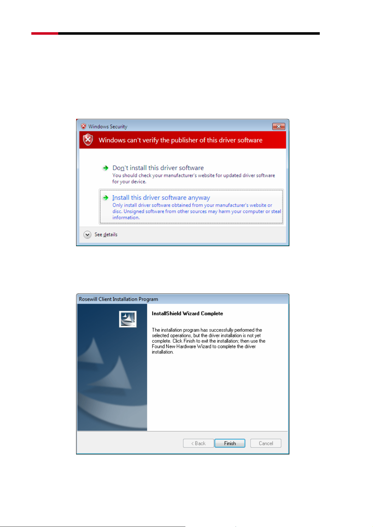
For Windows7, the Setup Wizard will notify you about the Windows Security with the
installation during these steps (shown in Figure 0-17). Ou
thoroughly, and are able to work with the operating system. Click Kpuvcnn" vjku" ftkxgt"
uqhvyctg"cp{yc{ to continue the installation.
r drivers have been tested
Figure 0-17
4. Then you will see Figure 0-18. Click Hkpkuj to complete.
Figure 0-18
-16-
Page 18

Fwcn"Dcpf"Yktgnguu"REK/G"Cfcrvgt"""""""""""""""""/"RNWD-N9003PCE/"""""""""""""""""""""""""""""""""Wugt‚u"Ocpwcn"
Ejcrvgt"5"Eqphkiwtcvkqp"Iwkfg"
503"Hqt"Ykpfqyu"ZR"
In Windows XP, N900PCE can be configured by Wireless N Client Utility. This
chapter describes how to configure your Adapter for wireless connectivity on
your Wireless Local Area Network (WLAN) and use the data security encryption
features.
After Installing the Adapter, the Adapter’s tray icon will appear in your
system tray. It appears at the bottom of the screen, and shows the signal strength
using color and the received signal strength indication (RSSI).
If the icon is gray, there is no connection.
If the icon is red, there is poor signal strength and the RSSI is less than 5dB.
If the icon is yellow, there is poor signal strength and the RSSI is between
5dB and 10dB.
If the icon is green, there is good signal strength and the RSSI is between
10dB and 20dB.
If the icon is green, there is excellent signal strength and the RSSI is more
than 20dB.
Double-click the icon and the Wvknkv{"will run. You can also run the utility by
clicking the Uvctv"→"Cnn"Rtqitcou"→"Yktgnguu"P"Enkgpv"Wvknkv{. The Utility
provides some integrated and easy tools to:
Display current status information
Edit and add configuration profiles
Display current diagnostics information
The section below introduces these above capabilities.
50303"Ewttgpv"Uvcvwu"
The Current Status tab contains general information about the program and its
operations. The Current Status tab needn’t any configurations.
-17-
Page 19

Fwcn"Dcpf"Yktgnguu"REK/G"Cfcrvgt"""""""""""""""""/"RNWD-N9003PCE/"""""""""""""""""""""""""""""""""Wugt‚u"Ocpwcn"
Figure 0-1
Vjg"hqnnqykpi"vcdng"fguetkdgu"vjg"kvgou"hqwpf"qp"vjg"Ewttgpv"Uvcvwu"uetggp0"
Rtqhkng"Pcog"/ This shows the name of current selected configuration profile.
The configuration of Profile name will be described on the Igpgtcn tab of
Rtqhkng"Ocpcigogpv.
Nkpm"Uvcvwu" / This shows whether the station is associated to the wireless
network.
Yktgnguu"Oqfg"/ Here displays the wireless mode.
Pgvyqtm"V{rg"/ The type of network and the station currently connected are
shown here. The options include:
Infrastructure (access point)
Ad Hoc
Pqvg<"
"
You can configure the network type and wireless mode on the Cfxcpegf tab of Rtqhkng"
Ocpcigogpv.
KR"Cfftguu"/ This displays the computer’s IP address.
Eqpvtqn"Ejcppgn"/ This shows the currently connected channel.
Fcvc"Gpet{rvkqp"/"Here"displays the encryption type the driver is using. You
-18-
Page 20

Fwcn"Dcpf"Yktgnguu"REK/G"Cfcrvgt"""""""""""""""""/"RNWD-N9003PCE/"""""""""""""""""""""""""""""""""Wugt‚u"Ocpwcn"
can configure it on the Ugewtkv{ tab of Rtqhkng"Ocpcigogpv.
Ugtxgt" Dcugf" Cwvjgpvkecvkqp" /" This" shows whether the server based
authentication is used.
Ukipcn"Uvtgpivj"/ This shows the strength of the signal.
Enkem"Advanced"qp"vjg"uetggp"cdqxg."{qw"ecp"ugg"cfxcpegf"kphqtocvkqp"cdqwv"vjg"rtqitco"cpf"kvu"
qrgtcvkqpu0"
50304"Rtqhkng"Ocpcigogpv"
Enkem"vjg"Rtqhkng"Ocpcigogpv"vcd"qh"vjg AWCU"cpf"vjg"pgzv"uetggp"yknn"crrgct"*ujqyp"kp"Hkiwtg"2/4Z+0"
Vjg"Rtqhkng"Ocpcigogpv"uetggp"rtqxkfgu"vqqnu"vq<"
Add a new profile
Modify a profile
Remove a profile
Activate a Profile
Import a Profile
Export a Profile
Scan Available Networks
Order profiles
Figure 0-2
-19-
Page 21

Fwcn"Dcpf"Yktgnguu"REK/G"Cfcrvgt"""""""""""""""""/"RNWD-N9003PCE/"""""""""""""""""""""""""""""""""Wugt‚u"Ocpwcn"
5030403"Cff"qt"Oqfkh{"c"Eqphkiwtcvkqp"Rtqhkng"
To add a new configuration profile, click Pgy on the Profile Management tab. To
modify a configuration profile, select the configuration profile from the Profile list
and click Oqfkh{. Then you will see the Management dialog box (shown in Figure
0-3).
30" Gfkv"vjg"Igpgtcn"vcd"
Rtqhkng" Pcog" / Please enter the Profile name which identifies the
configuration profile. This name must be unique. Note that the profile names
are not case-sensitive.
Enkgpv"Pcog"/ Please enter a name which identifies the client machine.
Pgvyqtm"Pcogu"*UUKFu+"/ Please enter the IEEE 802.11 wireless network
name. This field has a maximum limit of 32 characters.
Figure 0-3
40" Gfkv"vjg"Ugewtkv{"vcd"
Select the Security tab in the screen above, and then you can edit the fields to
configure the profile. To define the security mode, select the radio button of the
desired security mode as follows.
-20-
Page 22

Fwcn"Dcpf"Yktgnguu"REK/G"Cfcrvgt"""""""""""""""""/"RNWD-N9003PCE/"""""""""""""""""""""""""""""""""Wugt‚u"Ocpwcn"
Figure 0-4
YRC1YRC4< Wi-Fi Protected Access.
YRC1YRC4"Rcuurjtcug< Wi-Fi Protected Access Passphrase.
:2403z< Enables 802.1x security.
Rtg/Ujctgf" Mg{" *Uvcvke" YGR+< Enables the use of shared keys that are
defined on both the access point and the station. To define shared encryption
keys, choose the Shared Key radio button and click Eqphkiwtg"to fill in the
Define Shared Keys window (shown in Figure 0-5X).
Pqvg<"
"
The
Pqpg< No security (not recommended).
"
security mode is not available for 802.11n.
YGR
Pqvg<"
If the access point which the Adapter is associated has WEP set and the client has WEP
enabled, make sure that Cnnqy"Cuuqekcvkqp"vq"Okzgf"Egnnu is checked on the Security tab
to allow association. To complete WEP encryption configuration, you must select the 802.11
Authentication Mode as appropriate on the Cfxcpegf tab of this Rtqhkng" Ocpcigogpv
dialog.
-21-
Page 23

Fwcn"Dcpf"Yktgnguu"REK/G"Cfcrvgt"""""""""""""""""/"RNWD-N9003PCE/"""""""""""""""""""""""""""""""""Wugt‚u"Ocpwcn"
To configure the Encryption Keys under the Pre-Shared keys (Static WEP)
Security mode:
Figure 0-5
Pqvg<"
"
Select different
appropriate security option and configure the exact key as your need.
Ugewtkv{"Qrvkqpu
, the configurations are different; you can select the
"
50" Gfkv"vjg"Cfxcpegf"vcd"
This screen below allows you to make advanced configuration for the profile.
-22-
Page 24

Fwcn"Dcpf"Yktgnguu"REK/G"Cfcrvgt"""""""""""""""""/"RNWD-N9003PCE/"""""""""""""""""""""""""""""""""Wugt‚u"Ocpwcn"
Figure 0-6
Rqygt"Ucxg" Oqfg"/"Please select the power save mode in the drop-down
list."
Oczkowo / Selects maximum mode to let the access point buffer
incoming messages for the Adapter. The Adapter will detect the access
point if any messages are waiting periodically.
Pqtocn"/ Normal mode uses maximum when retrieving a large number
of packets, then switches back to power save mode after retrieving the
packets.
Qhh" / Turns power saving off, thus powering up the Wireless PCI-E
Adapter continuously for a short message response time.
Pgvyqtm"V{rg< There are basically two modes of networking:
Kphtcuvtwevwtg / All wireless clients will connect to an access point or
wireless Router.
Cf/Jqe / Directly connecting to another computer, for peer-to-peer
communication, using wireless network adapters on each computer,
such as two or more N900PCE wireless adapters.
"
-23-
Page 25

Fwcn"Dcpf"Yktgnguu"REK/G"Cfcrvgt"""""""""""""""""/"RNWD-N9003PCE/"""""""""""""""""""""""""""""""""Wugt‚u"Ocpwcn"
Pqvg<"
"
1) An Infrastructure network contains an Access Point or wireless Router. All the wireless
devices or clients will connect to the wireless Router or access point.
2) An Ad-Hoc network contains only clients, such as laptops with wireless desktop
adapters. All the adapters must be in Ad-Hoc mode to communicate."
Yktgnguu"Oqfg: Specifies 2.4 GHz 450 Mbps, 2.4 GHz 54 Mbps or 2.4 GHz
11 Mbps operation in an access point network. The Wireless adapter must
match the wireless mode of the access point with which it associates.
Yktgnguu" Oqfg" yjgp" Uvctvkpi" cp" HCf" JqeH"Pgvyqtm: Specifies 2.4 GHz
54/11 Mbps to start an Ad Hoc network if no matching network name is found
after scanning all available modes. This mode also allows the selection of the
channel that the Wireless Adapter uses. The channels available depend on
the regulatory domain. If the adapter finds no other ad hoc adapters, the
channel that the adapter starts the ad hoc network with will be selected
automatically. The Adapter must match the wireless mode and channel of the
clients it associates.
:24033" Cwvjgpvkecvkqp" Oqfg: Select which mode the Adapter uses to
authenticate to an access point:
Cwvq" /" Automatic causes the adapter to attempt authentication
using shared, but switches it to open authentication if shared fails.
Qrgp"/"Open System enables an adapter to attempt authentication
regardless of its WEP settings. It will only associate with the access
point if the WEP keys on both the adapter and the access point
match.
Ujctgf" /" Shared-key only allows the adapter to associate with
access points that have the same WEP key.
For infrastructure (access point) networks, click Rtghgttgf" CRu”" to specify four access
points at most to the client adapter that attempts to be associated to the access points. The
four access points have different priorities; the frontal has the higher priority.
-24-
Page 26

Fwcn"Dcpf"Yktgnguu"REK/G"Cfcrvgt"""""""""""""""""/"RNWD-N9003PCE/"""""""""""""""""""""""""""""""""Wugt‚u"Ocpwcn"
Figure 0-7
5030404"Tgoqxg"c"rtqhkng"
1. Go to the Profile Management tab (shown in Figure 0-2X).
2. Select the profile name in the Profiles List.
3. Click Tgoqxg.
Pqvg<"
"
The profile being used can’t be removed.
5030405"Uykvej"cpqvjgt"Rtqhkng"
1. Go to the Profile Management screen (shown in Figure 0-2X).
2. Select the profile name required in the Profiles List.
3. Click Cevkxcvg.
5030406"Gzrqtv"c"Rtqhkng"
1. From the Profile Management screen (shown in Figure 0-2X), highlight the
profile to export.
2. Click Gzrqtv”, the Export Profile window will then appear below.
3. Browse the directory to export the profile to.
4. Click Ucxg. The profile should then be exported to the specified location.
-25-
Page 27

Fwcn"Dcpf"Yktgnguu"REK/G"Cfcrvgt"""""""""""""""""/"RNWD-N9003PCE/"""""""""""""""""""""""""""""""""Wugt‚u"Ocpwcn"
Figure 0-8
5030407"Korqtv"c"Rtqhkng"
1. From the Profile Management screen (shown in Figure 0-2), click Korqtv”.
Then the Import Profile will appear below.
2. Browse to the directory where the profile is located.
3. Highlight the profile name.
4. Click Qrgp, the imported profile will then appear in the Profiles List.
Figure 0-9
-26-
Page 28

Fwcn"Dcpf"Yktgnguu"REK/G"Cfcrvgt"""""""""""""""""/"RNWD-N9003PCE/"""""""""""""""""""""""""""""""""Wugt‚u"Ocpwcn"
5030408"Uecp"Cxckncdng"Pgvyqtmu"
1. Click Uecp on the Profile Management screen (shown in Figure 0-2X), the
Available Infrastructure and Ad Hoc Networks window will appear below.
2. Click Tghtguj to refresh the list at any time.
3. Highlight a network name and click Cevkxcvg to connect to an available
network. If no configuration profile exists for that network, the Profile
Management window will open the Igpgtcn tab screen. Fill in the Profile
name and click QM to create the configuration profile for that network.
Figure 0-10
5030409"Cwvq"Rtqhkng"Ugngevkqp"Ocpcigogpv"
The auto selection feature allows the adapter to automatically select a profile
from the list of profiles and use it to connect to the network. To add a new profile
into the Auto Selected Profiles list, please follow these steps.
1. On the Profile Management screen (shown in Figure 0-2X), click Qtfgt"
Rtqhkngu”.
2. The Auto Profiles Selection management window will appear (shown in
Figure 0-11) with a list of all created profiles in the Available Profiles.
-27-
Page 29

Fwcn"Dcpf"Yktgnguu"REK/G"Cfcrvgt"""""""""""""""""/"RNWD-N9003PCE/"""""""""""""""""""""""""""""""""Wugt‚u"Ocpwcn"
Figure 0-11
3. Highlight the profiles to add to auto profile selection, and click Cff. The profile will appear in
the Auto Selected Profiles box.
4. Highlight a profile in the Auto Selected Profiles box.
5. Click Oqxg"Wr or Oqxg"Fqyp as appropriate.
Pqvg<"
"
The first profile in the Auto Selected Profiles box has highest priority, while the last profile
has the lowest priority.
6. Click QM.
7. Check the Cwvq"Ugngev"Rtqhkngu checkbox on the Rtqhkng"Ocpcigogpv tab
(shown in Figure 0-2).
Pqvg<"
"
When auto profile selection is enabled by checking Cwvq" Ugngev" Rtqhkngu on the Rtqhkng"
Ocpcigogpv tab, the client adapter will scan for an available network. The profile with the
highest priority and the same SSID as one of the found networks will be used to connect to
the network. If the connection fails, the client adapter will try the next highest priority profile
that matches the SSID until an available network is found.
-28-
Page 30

Fwcn"Dcpf"Yktgnguu"REK/G"Cfcrvgt"""""""""""""""""/"RNWD-N9003PCE/"""""""""""""""""""""""""""""""""Wugt‚u"Ocpwcn"
50305"Fkcipquvkeu"
The Fkcipquvkeu tab of the Wireless N Client Utility provides buttons used to retrieve
receiving and transmitting statistics. The Diagnostics tab does not require any configuration.
The Diagnostics tab lists the following receiving and transmitting diagnostics for frames
received or transmitted by the wireless network adapter:
Multicast frames transmitted and received
Broadcast frames transmitted and received
Unicast frames transmitted and received
Total bytes transmitted and received
Figure 0-12
5030503"Ejgem"Ftkxgt"Kphqtocvkqp"
Click the Cfcrvgt"Kphqtocvkqp button in the screen above, you will see the
adapter information, including general information about the wireless network
adapter and the Network Driver Interface Specification (NDIS) driver. Access the
adapter information from the Diagnostics tab.
Ectf"Pcog"/ The name of the wireless network adapter.
OCE"Cfftguu"/ The MAC address of the wireless network adapter.
Ftkxgt"/ The driver name and path of the wireless network adapter driver.
-29-
Page 31

Fwcn"Dcpf"Yktgnguu"REK/G"Cfcrvgt"""""""""""""""""/"RNWD-N9003PCE/"""""""""""""""""""""""""""""""""Wugt‚u"Ocpwcn"
Ftkxgt"Xgtukqp"/ The version of the wireless network adapter driver.
Ftkxgt"Fcvg"/ The creation date of the wireless network adapter driver.
Enkgpv"Pcog"/"The name of the client computer."
5030504"Ejgem"Tgegkxg"cpf"Vtcpuokv"Uvcvkuvkecn"Kphqtocvkqp"
The Cfxcpegf"Uvcvkuvkeu show receiving and transmitting statistical information
about the following receiving and transmitting diagnostics for frames received by
or transmitted to the wireless network adapter.
Figure 0-13
504"Hqt"Ykpfqyu"Xkuvc"
Wireless N Client Utility is not available for Windows Vista. So after the Adapter's
driver has been installed, please use the Windows WLAN Autoconfig to establish
a connection. Please follow the steps below.
1. Right-click the icon
pgvyqtm.
in your system tray, then click Eqppgev" vq" c"
-30-
Page 32

Fwcn"Dcpf"Yktgnguu"REK/G"Cfcrvgt"""""""""""""""""/"RNWD-N9003PCE/"""""""""""""""""""""""""""""""""Wugt‚u"Ocpwcn"
"
Figure 0-14
2. This page will then display and you will see the available wireless network list.
Select the SSID of your Access Point, take YCTG for example. Click
Eqppgev.
Figure 0-15
-31-
Page 33

Fwcn"Dcpf"Yktgnguu"REK/G"Cfcrvgt"""""""""""""""""/"RNWD-N9003PCE/"""""""""""""""""""""""""""""""""Wugt‚u"Ocpwcn"
3. If the key entered is correct, you will successfully connect to the network.
4. Click Enqug to finish.
"
Figure 0-16
Figure 0-17
-32-
"
Page 34

Fwcn"Dcpf"Yktgnguu"REK/G"Cfcrvgt"""""""""""""""""/"RNWD-N9003PCE/"""""""""""""""""""""""""""""""""Wugt‚u"Ocpwcn"
505"Hqt"Ykpfqyu"9"
Wireless N Client Utility is not available for Windows Vista. So after the Adapter's
driver has been installed, we have to use Windows WLAN Autoconfig to establish
a connection. Please follow the steps below.
1. Click the icon at the bottom of your screen in your system tray and then
you will see the available wireless network list. Select the SSID of your
Access Point and click Eqppgev.
"
Figure 0-18
2. If your wireless network is secured, you will be required to enter the security
key as shown in Figure 0-19. Enter the password in the Ugewtkv{"
Mg{"field,
take 3456789:;2 for example. And then click QM.
-33-
Page 35

Fwcn"Dcpf"Yktgnguu"REK/G"Cfcrvgt"""""""""""""""""/"RNWD-N9003PCE/"""""""""""""""""""""""""""""""""Wugt‚u"Ocpwcn"
"
Figure 0-19
3. If the key entered is correct, you will successfully connect to the network as
shown in Figure 0-20.
Figure 0-20
-34-
"
Page 36

Fwcn"Dcpf"Yktgnguu"REK/G"Cfcrvgt"""""""""""""""""/"RNWD-N9003PCE/"""""""""""""""""""""""""""""""""Wugt‚u"Ocpwcn"
Ejcrvgt"6"YRU"Eqphkiwtcvkqp"
WPS (Wi-Fi Protected Setup) function allows you to add a new wireless device to
an existing network quickly.
If the wireless Router supports Wi-Fi Protected Setup (WPS), you can establish a
wireless connection between wireless card and Router using either Push Button
Configuration (PBC) method or PIN method.
Pqvg<"
"
WPS function is not supported in Windows 7 OS.
First, the WPS software should be installed. Insert the Resource CD into your
CD-ROM drive. To continue, double-click O{"Eqorwvgt, and then double-click
the EF1FXF drive where the installation CD was placed. Open P;22REG folder,
and double-click yru0gzg. Then you will see Figure 0-1.
Figure 0-1
Then, please follow the step-by-step instruction to complete the WPS installation.
After that, WPS function can be enabled. Here we will introduce two ways to
configure the WPS.
-35-
Page 37

Fwcn"Dcpf"Yktgnguu"REK/G"Cfcrvgt"""""""""""""""""/"RNWD-N9003PCE/"""""""""""""""""""""""""""""""""Wugt‚u"Ocpwcn"
603"RDE"*Rwuj"Dwvvqp"Eqphkiwtcvkqp+"ogvjqf"
1. Firstly, press the WPS button directly on the front panel of the Router shown
in Figure 0-2.
Figure 0-2
2. Secondly, Double click the icon on the desktop to open the WPS Utility
and then you can see the welcome screen shown as Figure 0-3. Click Pgzv"
to continue0"Then select Rwuj"vjg"dwvvqp"qp"o{"ceeguu"rqkpv in the next
screen shown in Figure 0-4 and click Pgzv.
Figure 0-3
-36-
Page 38

Fwcn"Dcpf"Yktgnguu"REK/G"Cfcrvgt"""""""""""""""""/"RNWD-N9003PCE/"""""""""""""""""""""""""""""""""Wugt‚u"Ocpwcn"
Figure 0-4
3. Then wait a minute until Figure 0-5 appears. Click Hkpkuj to complete the
WPS configuration.
Figure 0-5
-37-
Page 39

Fwcn"Dcpf"Yktgnguu"REK/G"Cfcrvgt"""""""""""""""""/"RNWD-N9003PCE/"""""""""""""""""""""""""""""""""Wugt‚u"Ocpwcn"
604"RKP"ogvjqf"
There are two ways to configure the WPS by RKP"ogvjqf:
1) Enter a PIN into your AP device.
2) Enter the PIN from your AP device.
Following are the detailed configuration procedures of each way.
60403"Gpvgt"c"RKP"kpvq"{qwt"CR"fgxkeg"
1. Double-click the icon on the desktop to open the WPS Utility and then
you can see the welcome screen shown as Figure 0-3 Click Pgzv"to continue.
Figure 0-6 will appear. Select the second option and you will see the PIN
value of the adapter which is randomly generated. Click Pgzv.
Figure 0-6
2. Open the Router’s Web-based Utility and click YRU link on the left of the
main menu. Then 错误!未找到引用源。 will appear. Click" Cff" fgxkeg, then you can see
XFigure 0-7. Select Gpvgt"vjg"pgy"fgxkeg‚u"RKP"and enter the PIN value of
the adapter shown in Figure 0-7, click Eqppgev.
-38-
Page 40

Fwcn"Dcpf"Yktgnguu"REK/G"Cfcrvgt"""""""""""""""""/"RNWD-N9003PCE/"""""""""""""""""""""""""""""""""Wugt‚u"Ocpwcn"
Figure 0-7"
3. When Figure 0-5 appears, the WPS configuration is complete.
60404"Gpvgt"vjg"RKP"htqo"{qwt"CR"fgxkeg"
1. Open the WPS Utility and you will see Figure 0-3 . Click Pgzv" to continue.
Then Figure 0-8 will appear. Select the third option and enter the PIN value
which is labeled on the bottom of the Router. Click Pgzv.
Figure 0-8
2. When Figure 0-5 appears, the WPS configuration is complete.
Pqvg<"
"
If you generate a new PIN code for your Router, please enter the new one instead.
-39-
Page 41

Fwcn"Dcpf"Yktgnguu"REK/G"Cfcrvgt"""""""""""""""""/"RNWD-N9003PCE/"""""""""""""""""""""""""""""""""Wugt‚u"Ocpwcn"
Crrgpfkz"C<"HCS"
30" Jqy"fq"K"eqphkiwtg"vjg"Tqwvgt"vq"ceeguu"vjg"Kpvgtpgv"d{"CFUN"wugtuA"
1) First, configure the ADSL Modem configured in RFC1483 bridge model.
2) Connect the Ethernet cable from your ADSL Modem to the WAN port on
the Router. The telephone cord plugs into the Line port of the ADSL
Modem.
3) Log in to the Router, click the “Pgvyqtm” menu on the left of your browser,
and click "YCP" submenu. On the YCP page, select “PPPoE” for WAN
Connection Type. Type user name in the “User Name” field and
password in the “Password” field, finish by clicking Eqppgev.
Figure A-1 PPPoE Connection Type
4) If your ADSL lease is in “pay-according-time” mode, select “Connect on
Demand” or “Connect Manually” for Internet connection mode. Type an
appropriate number for “Max Idle Time” to avoid wasting paid time.
Otherwise, you can select “Auto-connecting” for Internet connection
mode.
-40-
Page 42

Fwcn"Dcpf"Yktgnguu"REK/G"Cfcrvgt"""""""""""""""""/"RNWD-N9003PCE/"""""""""""""""""""""""""""""""""Wugt‚u"Ocpwcn"
Figure A-2 PPPoE Connection Mode
Pqvg<
"
a) Sometimes the connection cannot be disconnected although you
specify a time to Max Idle Time, since some applications is visiting
the Internet continually in the background.
b) If you are a Cable user, please configure the Router following the
above steps.
40" Jqy"fq"K"eqphkiwtg"vjg"Tqwvgt"vq"ceeguu"vjg"Kpvgtpgv"d{"Gvjgtpgv"wugtuA"
1) Log in to the Router, click the “Pgvyqtm” menu on the left of your browser,
and click "YCP" submenu. On the YCP page, select “Dynamic IP” for
"WAN Connection Type", finish by clicking Ucxg.
2) Some ISPs require that you register the MAC Address of your adapter,
which is connected to your cable/DSL Modem during installation. If your
ISP requires MAC register, log in to the Router and click the "Pgvyqtm"
menu link on the left of your browser, and then click "OCE"Enqpg"
submenu link. On the "OCE"Enqpg" page, if your PC’s MAC address is
proper MAC address, click the Enqpg"OCE"Cfftguu button and your
PC’s MAC address will fill in the "WAN MAC Address" field. Or else, type
the MAC Address into the "WAN MAC Address" field. The format for the
-41-
Page 43

Fwcn"Dcpf"Yktgnguu"REK/G"Cfcrvgt"""""""""""""""""/"RNWD-N9003PCE/"""""""""""""""""""""""""""""""""Wugt‚u"Ocpwcn"
MAC Address is XX-XX-XX-XX-XX-XX. Then click the Ucxg button. It will
take effect after rebooting.
Figure A-3 MAC Clone
50" K"ycpv"vq"wug"PgvOggvkpi."yjcv"fq"K"pggf"vq"fqA"
1) If you start NetMeeting as a sponsor, you don’t need to do anything with
the Router.
2) If you start as a response, you need to configure Virtual Server or DMZ
Host and make sure the H323 ALG is enabled.
3) How to configure Virtual Server: Log in to the Router, click the
“Hqtyctfkpi” menu on the left of your browser, and click "Xktvwcn"
Ugtxgtu" submenu. On the "Xktvwcn"Ugtxgtu" page, click Cff"Pgy”.
Then on the “Cff"qt"Oqfkh{"c"Xktvwcn"Ugtxgt"Gpvt{” page, enter “1720”
for the “Service Port” blank, and your IP address for the “IP Address”
blank, taking 192.168.1.169 for an example, remember to Gpcdng and
Ucxg.
-42-
Page 44

Fwcn"Dcpf"Yktgnguu"REK/G"Cfcrvgt"""""""""""""""""/"RNWD-N9003PCE/"""""""""""""""""""""""""""""""""Wugt‚u"Ocpwcn"
Figure A-4 Virtual Servers
Figure A-5 Add or Modify a Virtual server Entry
Pqvg<"
"
Your opposite side should call your WAN IP, which is displayed on the “Status”
"
page.
4) How to enable DMZ Host: Log in to the Router, click the “Hqtyctfkpi”
menu on the left of your browser, and click "FO\" submenu. On the
"DMZ" page, click Gpcdng radio button and type your IP address into the
“DMZ Host IP Address” field, using 192.168.1.169 as an example,
remember to click the Ucxg button.
-43-
Page 45

Fwcn"Dcpf"Yktgnguu"REK/G"Cfcrvgt"""""""""""""""""/"RNWD-N9003PCE/"""""""""""""""""""""""""""""""""Wugt‚u"Ocpwcn"
Figure A-6 DMZ
5) How to enable H323 ALG: Log in to the Router, click the “Ugewtkv{” menu
on the left of your browser, and click “Dcuke"Ugewtkv{” submenu. On the
“Dcuke"Ugewtkv{” page, check the Gpcdng radio button next to J545"CNI.
Remember to click the Ucxg button.
Figure A-7 Basic Security
60" K"ycpv"vq"dwknf"c"YGD"Ugtxgt"qp"vjg"NCP."yjcv"ujqwnf"K"fqA"
1) Because the WEB Server port 80 will interfere with the WEB
management port 80 on the Router, you must change the WEB
management port number to avoid interference.
-44-
Page 46

Fwcn"Dcpf"Yktgnguu"REK/G"Cfcrvgt"""""""""""""""""/"RNWD-N9003PCE/"""""""""""""""""""""""""""""""""Wugt‚u"Ocpwcn"
2) To change the WEB management port number: Log in to the Router, click
the “Ugewtkv{” menu on the left of your browser, and click "Tgoqvg"
Ocpcigogpv" submenu. On the "Tgoqvg"Ocpcigogpv" page, type a
port number except 80, such as 88, into the "Web Management Port"
field. Click Ucxg and reboot the Router.
Figure A-8 Remote Management
Pqvg<"
"
If the above configuration takes effect, configure to the Router by typing
192.168.1.1:88 (the Router’s LAN IP address: Web Management Port) in the
address field of the Web browser.
3) Log in to the Router, click the “Hqtyctfkpi” menu on the left of your
browser, and click the "Xktvwcn"Ugtxgtu" submenu. On the "Xktvwcn"
Ugtxgtu" page, click Cff"Pgy”, then on the “Cff"qt"Oqfkh{"c"Xktvwcn"
Ugtxgt” page, enter “80” into the blank next to the “Ugtxkeg"Rqtv”, and
your IP address next to the “KR"Cfftguu”, assuming 192.168.1.188 for an
example, remember to Gpcdng and Ucxg.
-45-
Page 47

Fwcn"Dcpf"Yktgnguu"REK/G"Cfcrvgt"""""""""""""""""/"RNWD-N9003PCE/"""""""""""""""""""""""""""""""""Wugt‚u"Ocpwcn"
"
Figure A-9 Virtual Servers
Figure A-10 Add or Modify a Virtual server Entry
70" Vjg"yktgnguu"uvcvkqpu"ecppqv"eqppgev"vq"vjg"Tqwvgt0"
1) Make sure the "Gpcdng"Yktgnguu"Tqwvgt"Tcfkq" is checked.
2) Make sure that the wireless stations' SSID accord with the Router's
SSID.
3) Make sure the wireless stations have right KEY for encryption when the
Router is encrypted.
4) If the wireless connection is ready, but you can’t access the Router,
check the IP Address of your wireless stations.
-46-
Page 48

Fwcn"Dcpf"Yktgnguu"REK/G"Cfcrvgt"""""""""""""""""/"RNWD-N9003PCE/"""""""""""""""""""""""""""""""""Wugt‚u"Ocpwcn"
Crrgpfkz"D<"Eqphkiwtkpi"vjg"RE"
In this section, we’ll introduce how to install and configure the TCP/IP correctly in
Windows XP. First make sure your Ethernet Adapter is working, refer to the
adapter’s manual if necessary.
30" Eqphkiwtg"VER1KR"eqorqpgpv"
1) On the Windows taskbar, click the Uvctv button, and then click Eqpvtqn"
Rcpgn.
2) Click the Pgvyqtm"cpf"Kpvgtpgv"Eqppgevkqpu icon, and then click on the
Pgvyqtm"Eqppgevkqpu tab in the appearing window.
3) Right click the icon that showed below, select Properties on the prompt
page.
Hkiwtg"D/3"
4) In the prompt page that showed below, double click on the Kpvgtpgv"
Rtqvqeqn"*VER1KR+.
-47-
Page 49

Fwcn"Dcpf"Yktgnguu"REK/G"Cfcrvgt"""""""""""""""""/"RNWD-N9003PCE/"""""""""""""""""""""""""""""""""Wugt‚u"Ocpwcn"
Hkiwtg"D/4"
5) The following VER1KR"Rtqrgtvkgu window will display and the KR"Cfftguu"
tab is open on this window by default.
Now you have two ways to configure the VER1KR"protocol below:
Ugvvkpi"KR"cfftguu"cwvqocvkecnn{"
Select Qdvckp"cp"KR"cfftguu"cwvqocvkecnn{, Choose Qdvckp"FPU"ugtxgt"
cwvqocvkecnn{, as shown in the Figure below:
-48-
Page 50

Fwcn"Dcpf"Yktgnguu"REK/G"Cfcrvgt"""""""""""""""""/"RNWD-N9003PCE/"""""""""""""""""""""""""""""""""Wugt‚u"Ocpwcn"
Hkiwtg"D/5"
Pqvg<"For Windows 98 OS or before, the PC and Router may need to be
"
restarted.""
Ugvvkpi"KR"cfftguu"ocpwcnn{
Select Wug"vjg"hqnnqykpi"KR"cfftguu"radio button. And the following items
1
"
available
2 If the Router's LAN IP address is 192.168.1.1, specify the KR"cfftguu as
192.168.1.x (x is from 2 to 254), and the Uwdpgv"ocum as 255.255.255.0.
3
Type the Router’s LAN IP address (the default IP is 192.168.1.1) into the
Fghcwnv"icvgyc{"field.
-49-
Page 51

Fwcn"Dcpf"Yktgnguu"REK/G"Cfcrvgt"""""""""""""""""/"RNWD-N9003PCE/"""""""""""""""""""""""""""""""""Wugt‚u"Ocpwcn"
Select Wug"vjg"hqnnqykpi"FPU"ugtxgt"cfftguugu. In the Rtghgttgf FPU"
4
Ugtxgt"field you can enter the same value as the Fghcwnv"icvgyc{"or type
the local DNS server IP address.
Pqy<
Click QM to keep your settings.
Hkiwtg"D/6
-50-
Page 52

Fwcn"Dcpf"Yktgnguu"REK/G"Cfcrvgt"""""""""""""""""/"RNWD-N9003PCE/"""""""""""""""""""""""""""""""""Wugt‚u"Ocpwcn"
Crrgpfkz"E<"Urgekhkecvkqpu"
Igpgtcn
Interface PCI-E Interface
Standards IEEE802.11a; IEEE802.11b; IEEE802.11g;
IEEE802.11n; IEEE802.1x
Operating System Windows XP / Windows Vista / Windows 7
Radio Data Rate 11a: 6/9/12/18/24/36/48/54Mbps
11b: 1/2/5.5/11Mbps
11g: 6/9/12/18/24/36/48/54Mbps
11n: Up to 450Mbps
11a: OFDM; 11b: CCK, QPSK, BPSK; 11g: OFDM;
Modulation
11n: QPSK, BPSK, 16-QAM, 64-QAM
Media Access Protocol CSMA/CA with ACK
Data Security 64/128/152-bit WEP; WPA/WPA2; WPA-PSK/WPA2-PSK; TKIP/AES
Frequency 2.4 ~ 2.4835GHz, 5.150 ~ 5.250GHz, 5.250~5.350GHz, 5.745 ~
5.825GHz
Spread Spectrum Direct Sequence Spread Spectrum (DSSS)
Safety & Emissions FCC, CE, RoHS,
Gpxktqpogpvcn"cpf"Rj{ukecn"
Operating : 0℃~40℃ (32℉~104℉)
Temperature.
Storage: -40℃~70℃ (-40℉~158℉)
Humidity
Operating: 10% - 90% RH, Non-condensing
Storage: 5% - 90% RH, Non-condensing
Dimension 2.56 x 2.56 x 2.56 in. (6.5 x 6.5 x 6.5 cm) without bracket
Weight 2.99 oz (85g) with 3x 2dBi Antenna
* 1. Only 2.412GHz~2.462GHz is allowed to be used in USA, which means only channel 1~11 is
available for American users to choose.
2. Rules on the use of 5GHz band channels may vary according to different national laws.
Thank you for purchasing a quality Rosewill Product.
Please register your product at: www.rosewill.com for complete warranty information and future
support for your product.
"
Tqugyknn"Ewuvqogt"Ugtxkeg"Jqvnkpg<"3/:22/797/;::7"
Tqugyknn"Ewuvqogt"Ugtxkeg"Uwrrqtv<"
-51-
techsupport@rosewill.com"
Page 53

Fwcn"Dcpf"Yktgnguu"REK/G"Cfcrvgt"""""""""""""""""/"RNWD-N9003PCE/"""""""""""""""""""""""""""""""""Wugt‚u"Ocpwcn"
EQR[TKIJV"("VTCFGOCTMU
"
Specifications are subject to change without notice. is a registered
trademark of Rosewill Inc. Other brands and product names are trademarks or
registered trademarks of their respective holders.
No part of the specifications may be reproduced in any form or by any means or
used to make any derivative such as translation, transformation, or adaptation
without permission from Rosewill Inc. Copyright © 2010 Rosewill Inc. All rights
reserved.
jvvr<11yyy0tqugyknn0eqo"
HEE"UVCVGOGPV"
"
This equipment has been tested and found to comply with the limits for a Class B digital device,
pursuant to part 15 of the FCC Rules. These limits are designed to provide reasonable protection
against harmful interference in a residential installation. This equipment generates, uses and can
radiate radio frequency energy and, if not installed and used in accordance with the instructions,
may cause harmful interference to radio communications. However, there is no guarantee that
interference will not occur in a particular installation. If this equipment does cause harmful
interference to radio or television reception, which can be determined by turning the equipment
off and on, the user is encouraged to try to correct the interference by one or more of the
following measures:
Reorient or relocate the receiving antenna.
Increase the separation between the equipment and receiver.
Connect the equipment into an outlet on a circuit different from that to which the
receiver is connected.
Consult the dealer or an experienced radio/ TV technician for help.
This device complies with part 15 of the FCC Rules. Operation is subject to the following two
conditions:
1)
This device may not cause harmful interference.
This device must accept any interference received, including interference that may
2)
cause undesired operation.
Any changes or modifications not expressly approved by the party responsible for compliance
could void the user’s authority to operate the equipment.
NOTE: THE MANUFACTURER IS NOT RESPONSIBLE FOR ANY RADIO OR
TV INTERFERENCE CAUSED BY UNAUTHORIZED MODIFICATIONS TO
THIS EQUIPMENT. SUCH MODIFICATIONS COULD VOID THE USER’S
AUTHORITY TO OPERATE THE EQUIPMENT.
HEE"TH"Tcfkcvkqp"Gzrquwtg"Uvcvgogpv
This equipment complies with FCC RF radiation exposure limits set forth for an uncontrolled environment.
This device and its antenna must not be co-located or operating in conjunction with any other antenna or
"
-52-
Page 54

Fwcn"Dcpf"Yktgnguu"REK/G"Cfcrvgt"""""""""""""""""/"RNWD-N9003PCE/"""""""""""""""""""""""""""""""""Wugt‚u"Ocpwcn"
transmitter.
“To comply with FCC RF exposure compliance requirements, this grant is applicable to only Mobile
Configurations. The antennas used for this transmitter must be installed to provide a separation distance of
at least 20 cm from all persons and must not be co-located or operating in conjunction with any other
antenna or transmitter.”
EG"Octm"Yctpkpi"
This is a class B product. In a domestic environment, this product may cause radio interference, in which
case the user may be required to take adequate measures.
Pcvkqpcn"tguvtkevkqpu"
This device is intended for home and office use in all EU countries (and other countries following the EU
directive 1999/5/EC) without any limitation except for the countries mentioned below:
Eqwpvt{" Tguvtkevkqp" Tgcuqp1tgoctm"
Bulgaria None
Outdoor use limited to 10
France
mW e.i.r.p. within the
band 2454-2483.5 MHz
Italy None
Luxembourg None
Norway Implemented
Russian
None Only for indoor applications
Federation
Note: Please don’t use the product outdoors in France.
Kpfwuvt{"Ecpcfc"uvcvgogpv<
General authorization required for outdoor
use and public service
Military Radiolocation use. Refarming of the 2.4
GHz band has been ongoing in recent years to
allow current relaxed regulation. Full
implementation planned 2012
If used outside of own premises, general
authorization is required
General authorization required for network and
service supply(not for spectrum)
This subsection does not apply for the
geographical area within a radius of 20 km from the
centre of Ny-Ålesund
This device complies with RSS-210 of the Industry Canada Rules. Operation is subject to the following two
conditions:
(1) This device may not cause harmful interference, and (2) this device must accept any interference
received, including interference that may cause undesired operation.
KORQTVCPV"PQVG<"
Tcfkcvkqp"Gzrquwtg"Uvcvgogpv<"
This equipment complies with IC radiation exposure limits set forth for an uncontrolled environment. This
-53-
Page 55

Fwcn"Dcpf"Yktgnguu"REK/G"Cfcrvgt"""""""""""""""""/"RNWD-N9003PCE/"""""""""""""""""""""""""""""""""Wugt‚u"Ocpwcn"
equipment should be installed and operated with minimum distance 20cm between the radiator & your body.
This device has been designed to operate with an antenna having a maximum gain of 2 dBi. Antenna having
a higher gain is strictly prohibited per regulations of Industry Canada. The required antenna impedance is 50
ohms.
Uchgv{"Yctpkpi"
Place connecting cables carefully so that no one will step on them or stumble over
them.
Always disconnect all cables from this device before servicing or disassembling.
Use ONLY an appropriate power adaptor or cord for your device.
Connect the power adaptor or cord to the right supply voltage (for example, 110V AC in
North America or 230V AC in Europe).
Do not allow anything to rest on the power adaptor or cord and do not place the product
where anyone can walk on the power adaptor or cord.
Do not use the device if the power adaptor or cord is damaged as it might cause
electrocution.
If the power adaptor or cord is damaged, remove it from the power outlet.
Do not attempt to repair the power adaptor or cord. Contact your local vendor to order a
new one.
Do not use the device outside, and make sure all the connections are indoors.
Do not obstruct the device ventilation slots, as insufficient airflow may harm your
device.
Do not use this product near water, eg, in wet basement, or near a swimming pool.
Do not expose your device to dampness, dust or corrosive liquids.
Do not install, use, or service this device during a thunderstorm. There is a remote risk
of electric shock from lightning.
Connect ONLY suitable accessories to the device.
Do not open the device or unit. Opening or removing covers can expose you to
dangerous high voltage points or other risks. ONLY qualified service personnel should
service or disassemble this device. Please contact your vendor for further information.
Make sure to connect the cables to the correct ports.
If you wall mount your device, make sure that no electrical lines, gas or water pipes will
be damaged.
"
[qwt"rtqfwev"ku"octmgf"ykvj"vjku"u{odqn."yjkej"ku"mpqyp"cu"vjg"YGGG"octm0"YGGG"
uvcpfu"hqt"Ycuvg"Gngevtqpkeu"cpf"Gngevtkecn"Gswkrogpv0"Kv"ogcpu"vjcv"wugf"gngevtkecn"
cpf"gngevtqpke"rtqfwevu"ujqwnf"pqv"dg"okzgf"ykvj"igpgtcn"y cuvg0"Wugf"gngevtkecn"
cpf"gngevtqpke"gswkrogpv"ujqwnf"dg"vtgcvgf"ugrctcvgn{0"
"
-54-
"
 Loading...