

Page 1

User’s Manual
Page 2
Page 3

Front panel
Front 3x 120mm fans
Front dust filter
Page 4
3
© All rights reserved by Rosewill
User ManualRISE
CASE
Accessory Box
1 x M/B standoff socket Motherboard
21 x Screw A
3.5” HDD
+
Motherboard
8 x Screw C PSU
28 x Screw B 2.5” HDD/SSD
3 x Cable tie Cables
Page 5
4
© All rights reserved by Rosewill
1.
2.
User ManualRISE
CASE
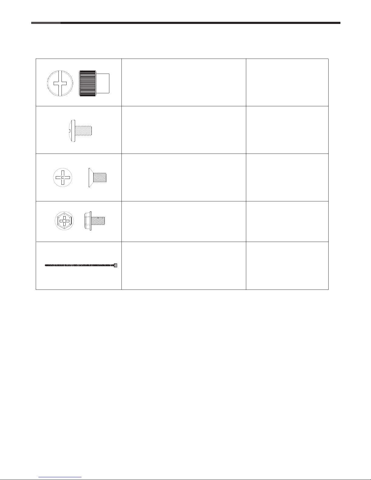
Unscrew to remove left and right panels.
Place the power supply from the left side into
the chassis and secure with screws.
NOTICE :
-If your power supply is equipped with single
fan (120mm, 135mm or 140mm), please have
the fan face to the bottom.
-Please remember to clean the PSU dust
filter regularly or insufficient air intake may
fail your power supply permanently.
**Unscrew to remove the cover to install the
secondary PSU if necessary.
Page 6

5
© All rights reserved by Rosewill
3.
User ManualRISE
CASE
-Place the motherboard onto stand-offs and secure with screws.
Micro-ATX
ATX
E-ATX
* Screw A
Motherboard Compatibility
Page 7

6
© All rights reserved by Rosewill
4.
User ManualRISE
CASE
-Unscrew to remove expansion slot cover.
-Secure with thumb screw.
C
A
-Install the add-on card into its position.
B
Page 8

Page 9

8
© All rights reserved by Rosewill
7.
User ManualRISE
CASE
- Unscrew the screws to remove the
HDD/SSD mount.
*Screw B
- Reinstall the HDD/SSD mount into
position.
- Unscrew the screws to
remove the HDD/SSD
mount cover.
- Screw the 3.5”/2.5”
HDD/SSD onto the
mount, and reinstall the
cover back to the mount.
(RISE GLOW ONLY)
Page 10

Page 11

10
© All rights reserved by Rosewill
User ManualRISE
CASE
10.
Make sure all necessary cables and wires
are connected, then reinstall side panels
and secure with screws.
Page 12

Page 13

12
© All rights reserved by Rosewill
User ManualRISE
CASE
Thank you for purchasing a High-Quality Rosewill Product.
Please regoster your product at : http://www.rosewill.com
for complete warranty information and future support for your product.
If you have any question while using our products, please visit our website : www.rosewill.com
for user manual or feel free to contact us.
Support Phone Number: 800-575-9885
Support Email: techsupport@rosewill.com
Appendix B :
How to remove the POP out dust filter ( front & top)
By default, the pop out dust filter doors are locked down by one thumb screws to prevent damage during
transport. The thumb screws will first need to be removed before the dust filter doors can be easily popped
in and out. Should you prefer to disable the pop out feature, simply leave the thumb screw in place.
Remove the Front and then the Top panel of the case.
Locate the thumb screw and twist counterclockwise to remove.
Push down on the highlighted spots simultaneously
to unlatch the dust filter for removal.
A click sound can be heard.
Push down on the highlighted spots simultaneously
to latch in the dust filter when maintenance is complete.
A click sound can be heard.
Page 14

www.rosewill.com
 Loading...