

Page 1

FIXED WALL MOUNT FOR
LCD, PLASMA, and LED DISPLAYS
RHTB-11003
User Manual
Page 2
FIXED WALL MOUNT FOR LCD, PLASMA, and LED DISPLAYS RHTB-11003 User Manual
1
Contents
English
……………………………………………………………
P02
Français
……………………………………………………………
P06
Español
……………………………………………………………
P10
……………………………………………………………
P14
……………………………………………………………
P18
Page 3
FIXED WALL MOUNT FOR LCD, PLASMA, and LED DISPLAYS RHTB-11003 User Manual
2
English
SPECIFICATIONS
Display Size: 26” to 46”
Maximum Load: 45 kg (100 lbs)
Mounting Pattern: 400 mm x 400 mm (15.7” x 15.7”) max
Profile: 2.8 cm (1.1”)
BOX CONTENTS
Wall Plate (x1)
Mount Arm (x2)
Instruction Manual (x1)
Hardware Kit (x1)
WARNINGS
1. Read these instructions before you begin. If you are unsure of any part of the process, contact a
professional contractor or installer for assistance. Improper installation can result in injury or damage.
2. The wall or mounting surface must be capable of supporting the combined weight of the mount and
the display; if not, the structure must be reinforced.
3. Locate pipes, wires, or any other hazards in the wall where you wish to install the mount before
drilling.
4. Safety gear and proper tools must be used. Failure to do so can result in injury or damage.
5. Two people are recommended for installation. Do not attempt to lift a heavy display without
assistance.
6. Follow all instructions and recommendations regarding adequate ventilation and suitable locations for
mounting your display. Consult the owner‘s manual for your particular display for more information.
CAUTION: This wall mount is intended for use only with the maximum weight of 45 kg (100 lbs). Use with heavier
than the maximum weights indicated may result in instability causing possible injury.
TOOLS REQUIRED
Phillips Head Screw Driver
Electric or Portable Drill
3 mm (1/8”) Drill Bit and Stud Finder for Drywall Installation
8 mm (5/16”) Masonry Bit for Concrete Installation
Level
Page 4
FIXED WALL MOUNT FOR LCD, PLASMA, and LED DISPLAYS RHTB-11003 User Manual
3
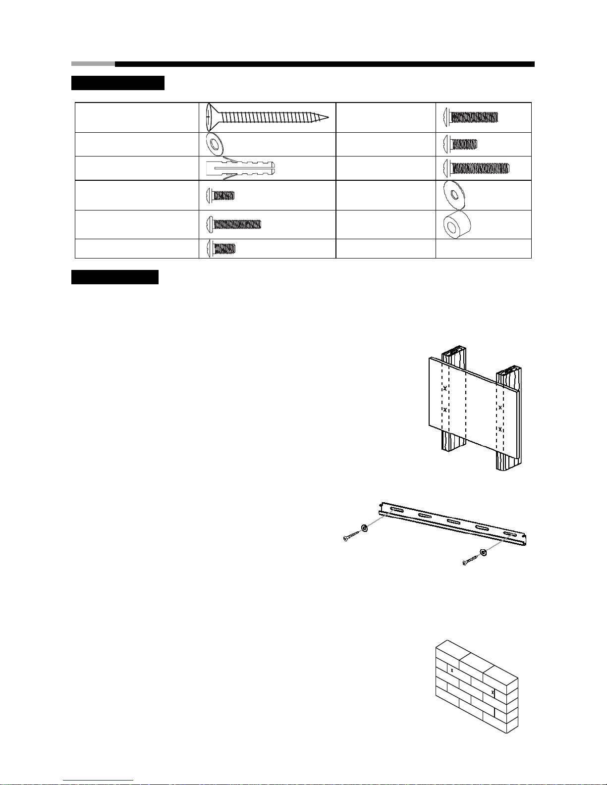
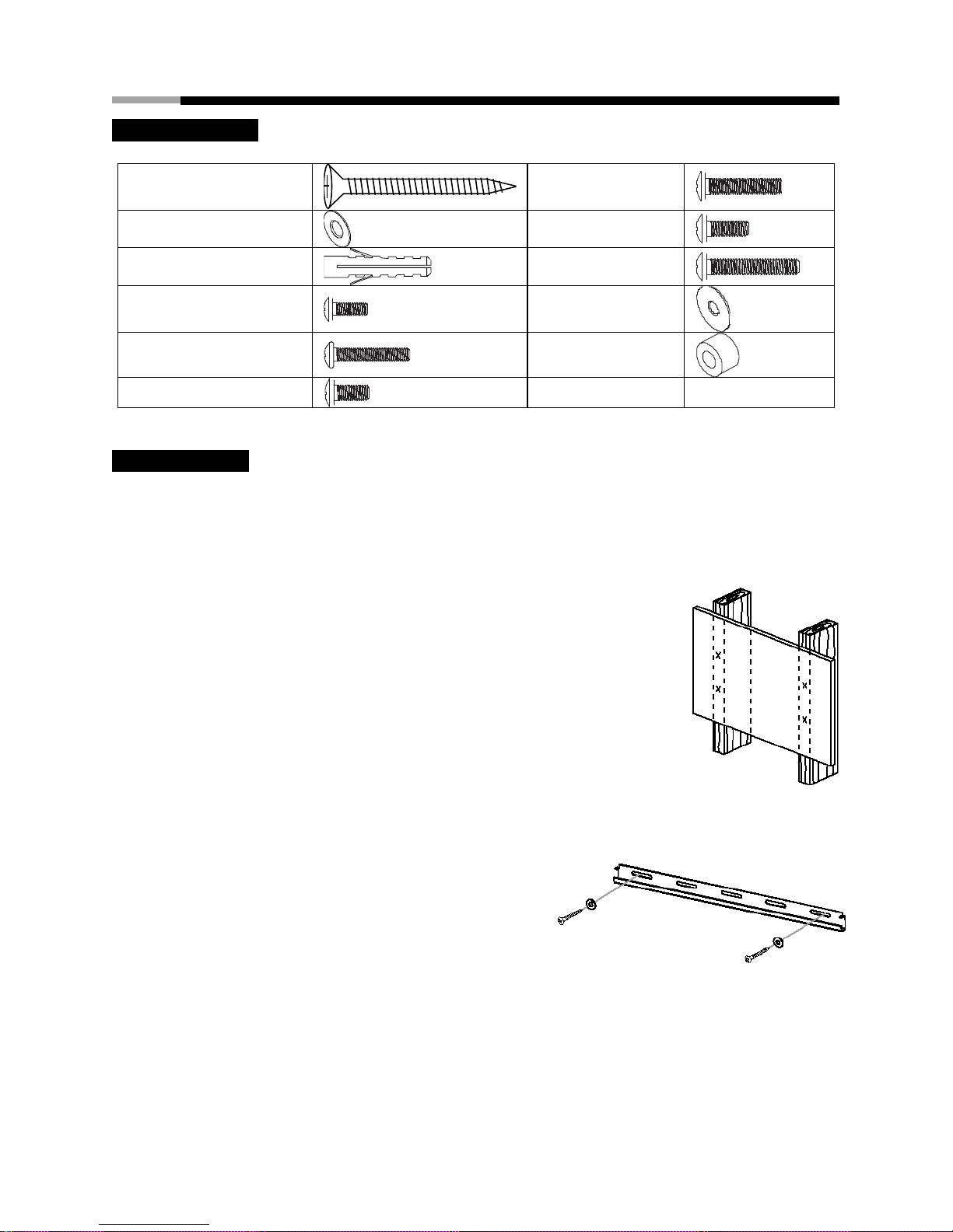
HARDWARE KIT
(A) M6.3 x 63 Screw (x2)
(G) M6 x 30 Screw
(x4)
(B) Washer (x2)
(H) M8 x 12 Screw
(x4)
(C) Concrete Anchor (x2)
(I) M8 x 30 Screw (x4)
(D) M4 x 12 Screw (x4)
(J) M6 Washer (x4)
(E) M4 x 20 Screw (x4)
(K) Spacer (x8)
(F) M6 x 12 Screw (x4)
INSTALLATION
Part 1A – Mounting to the Wall (Drywall)
IMPORTANT! For safety reasons, this mount must be secured to at least two wood studs no less than 16” apart.
The studs must be capable of supporting the combined weight of the mount and display.
1. Use a high quality stud finder to locate two adjacent studs where you
wish to install y our mount. Mark both edges of each stud to help identify
the exact center.
NOTE: You must use the center of each stud to avoid cracking or
splitting the wood during installation.
2. Place the wall plate against the wall over the marked studs. Make sure it
is level.
3. While another person holds the wall plate in position, mark two locations
(one per stud) for securing the mount to the wall.
4. Set the wall plate aside and drill a 3 mm (1/8”) pilot hole at each marked location.
5. Place the wall plate back against the wall and
attach it using the M6.3 x 63 screws (A) and
washers (B) provided. Do not over-tighten these
screws and do not release the wall plate until
both screws are in place. Ensure that the wall
plate remains level after all screws are secured.
Part 1B – Mounting to the Wall (Concrete)
IMPORTANT! For safety reasons, the concrete wall must be capable of supporting the combined weight of the
mount and the display. The manufacturer takes no responsibility for failure caused by walls of insufficient strength.
1. Place the wall plate against the wall in the desired location. Make sure it is
level.
2. While another person holds the wall plate in place, mark two locations on
the wall for s ecuring the mount.
3. Set the wall plate aside and drill an 8 mm (5/16”) hole at each marked
location. Remove any excess dust from the holes.
Page 5
FIXED WALL MOUNT FOR LCD, PLASMA, and LED DISPLAYS RHTB-11003 User Manual
4
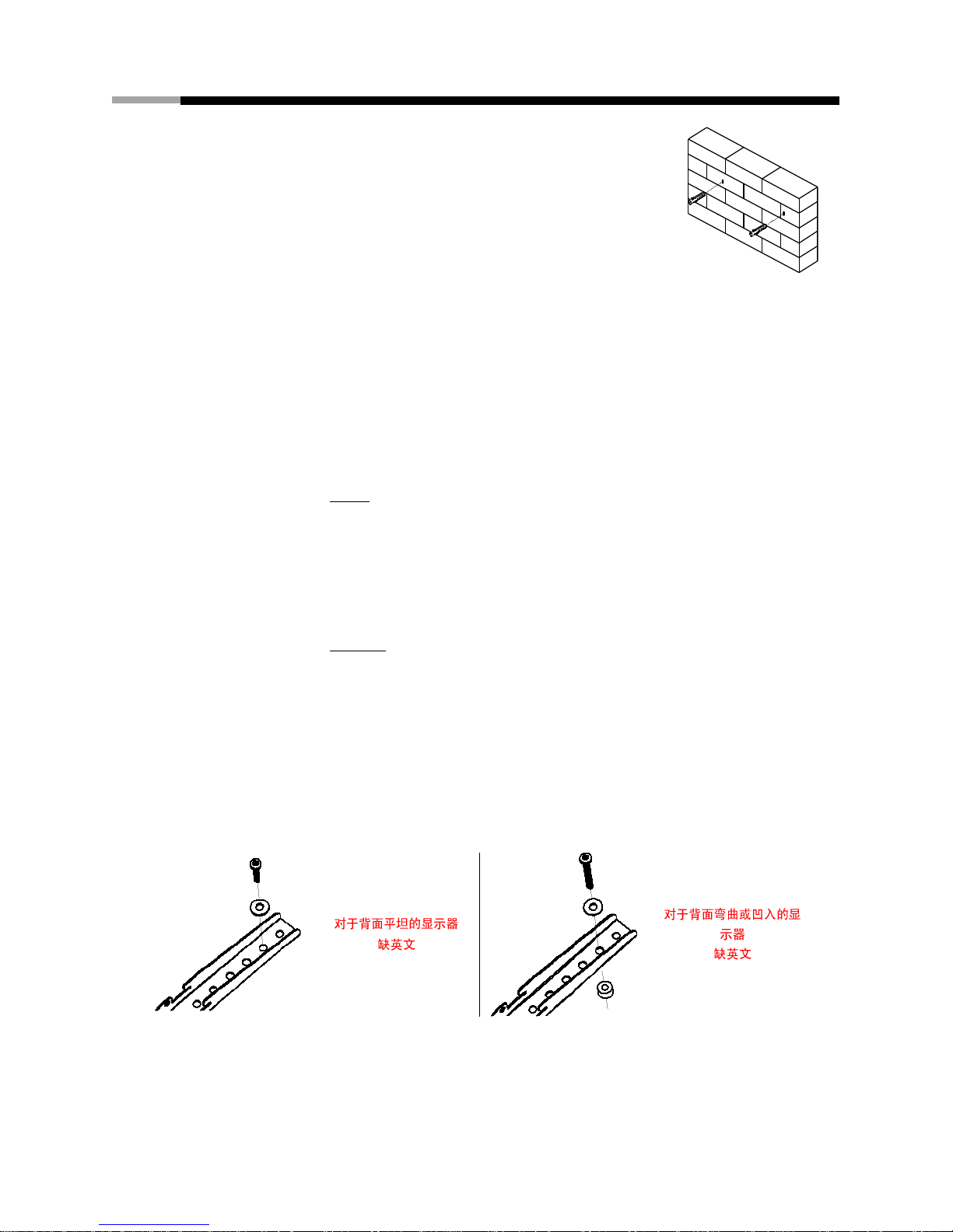
4. Insert a concrete anchor (C) into each hole so that it is flush with the
concrete surface. A hammer can be used to lightly tap the anchors into
place if necessary.
NOTE: If the concrete wall is covered by a layer of plaster or drywall, the
concrete anchor must pass completely through the layer to rest flush with
the concrete surfa ce.
5. Place the wall plate back against the wall and attach it using the M6.3 x 63
screws (A) and washers (B) provided. Do not over-tighten these screws
and do not release the wall plate until both screws are in place. Ensure that the wall plate
remains level after all screws are secured.
Part 2 – Attaching the Mount Arms to the Display
IMPORTANT! Use extra care during this part of the installation. If possible, avoid placing your display facedown
as it may damage the viewing surface.
NOTE: This mount comes with a selection of different screw diameters and lengths to accommodate a wide
variety of display models. Not all of the hardware in the kit will be used. If you cannot find the appropriate screw
size in the kit provided, consult the manufacturer of your display for more information.
1. Determine the correct length of screw to use by examining the back of your display:
A. If the back of your display is flat and the mounting holes are flush with the surface, you will
use the shorter screws (D, F, or H) from the hardware kit.
B. If the back of your display is curved, has a protrusion, or if the mounting holes are
recessed, you will need to use the longer screws (E, G, or I) and may also need to use the
spacers (K).
2. Determine the correct diameter of screw to use by carefully trying one of each size (M4, M6 and M8)
from the hardware kit. Do not force any of the screws – if you feel resistance stop immediately
and try a smaller diameter screw.
3. Attach the mount arms to the back of your display using the screws identified in steps 1 and 2:
A. If you are using the M4 or M6 screws you will also need to use the M6 washers (J). M8
screws do not require washers.
B. If you are using the longer screws on a display with a curved or recessed back, you may
also need to use the spacers (K). Use one spacer or two spacers stacked as needed.
Only use a spacer if necessary.
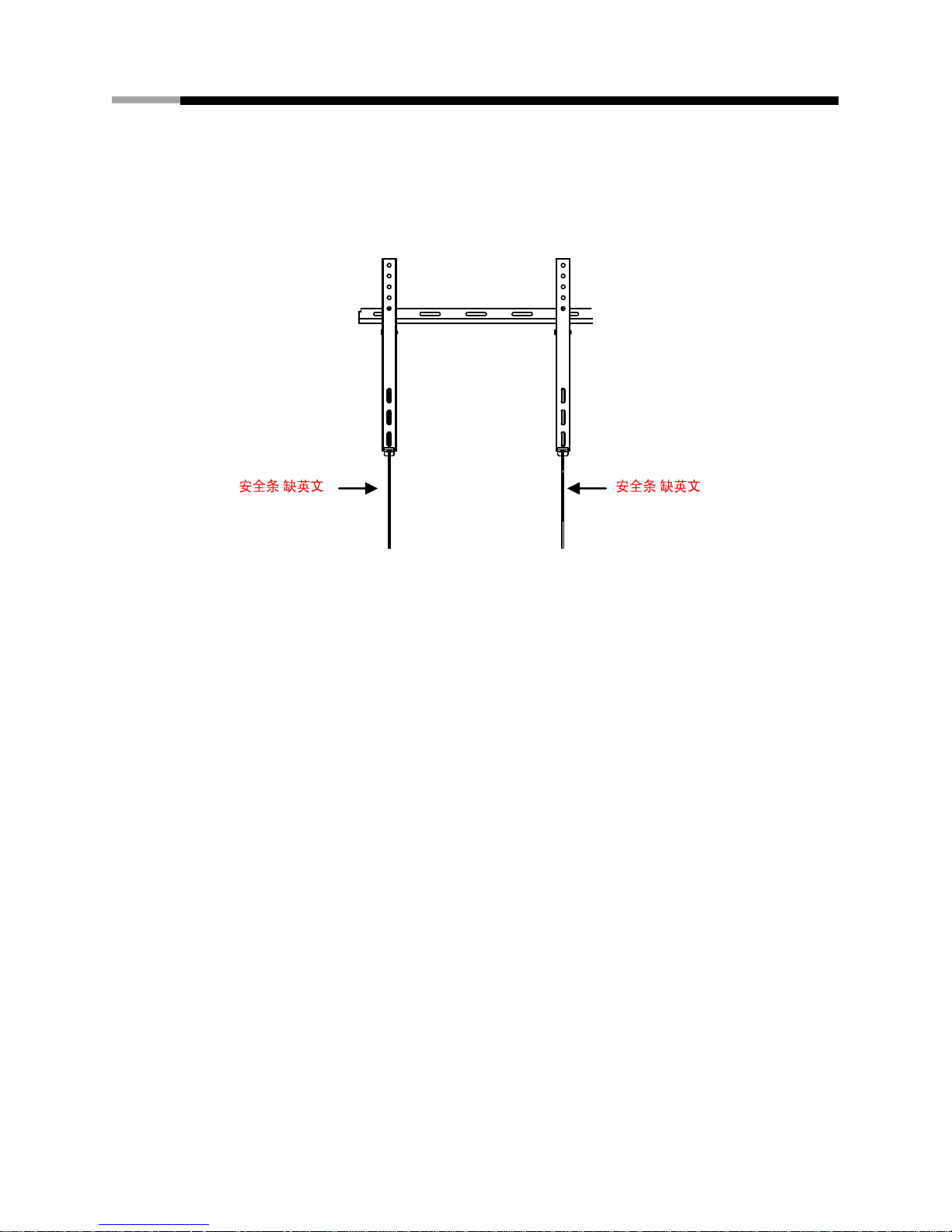
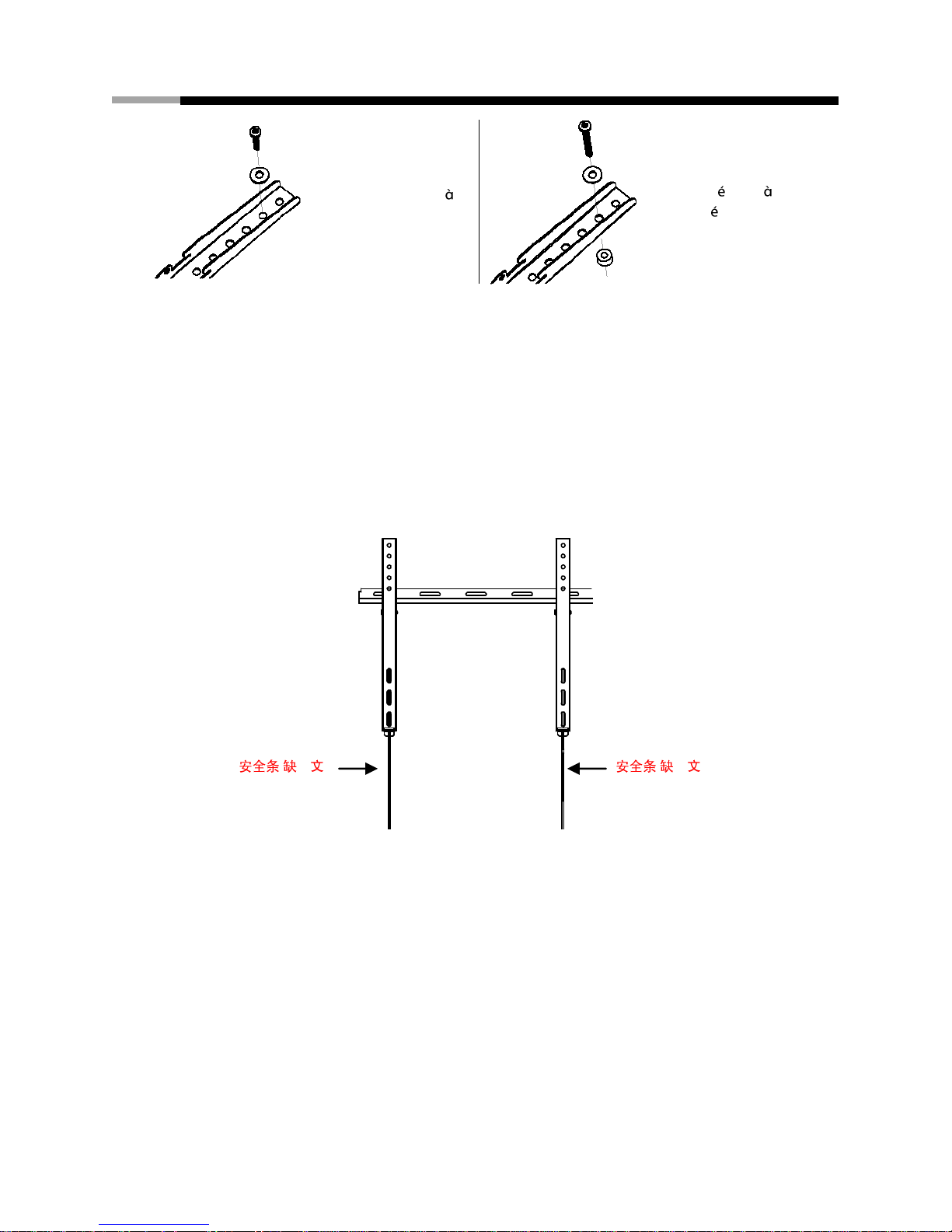
Part 3 – Final Assembly
1. With the help of another person, carefully lift your display and place it on the mount. Do not release
the display until the mount arms have securely hooked onto the mount.
( )
( )
Page 6
FIXED WALL MOUNT FOR LCD, PLASMA, and LED DISPLAYS RHTB-11003 User Manual
5
2. Make sure the safety locks have successfully engaged by gently pushing up on the display. You
should not be able to remove the display from the mount.
3. If you need to remove the display from the mount, pull the plastic tabs located at the bottom of the
mount arms down and then forward (away from the wall) to disengage the safety locks. With the help
of another person, carefully lift the display from the mount. Return the tabs to their original position by
pulling them down and pushing them backwards.
4. Periodically clean your mount with a dry cloth. Inspect all screws and hardware at regular intervals to
ensure that no connections have become loose over time. Re-tighten as needed.
( )
( )
Page 7
FIXED WALL MOUNT FOR LCD, PLASMA, and LED DISPLAYS RHTB-11003 User Manual
6
Français
CARACTÉRISTIQUES
Taille de l’écran : 26” à 46”
Charge maximale : 45 kg (100 lbs)
Modèle demontage : 400 mm x 400 mm (15,7” x 15,7”) max
Profilé : 7,2 cm (2,8”)
CONTENU DE LA BOÎTE
Plaque murale (x1)
Bras du support (x2)
Mode d’emploi (x1)
Kit de quincaillerie (x1)
AVERTISSEMENTS
1. Veuillez lire ce mode d’emploi avant de commencer le travail. Si vous avez des incertitudes
concernant une partie de la procédure, veuillez demander de l’aide auprès d’un entrepreneur ou d’un
installateur spécialisé. Une installation incorrecte peut occasionner des blessures ou des dégâts
matériels.
2. Le mur ou la surface de montage doit être en mesure de supporter le poids combiné du support et de
l’écran. Dans le cas contraire, la structure devra être renforcée.
3. Avant de commencer à percer, localisez les tuyaux, câbles ou toute autre source de risque dans le
mur où vous souhaitez installer le support.
4. Il convient d’utiliser un équipement de protection et des outils adaptés. Le nonrespect de ces
précautions peut entraîner des blessures ou des dégâts matériels.
5. La présence de deux personnes est recommandée pour l’installation. N’essayez pas de soulever un
écran lourd sans assistance.
6. Veuillez observer l’ensemble des consignes et recommandations relatives à une ventilation
appropriée et à des emplacements adaptés au montage de votre écran. Veuillez consulter la ‘notice
du fabricant de votre écran pour toute information complémentaire..
ATTENTION : Ce support mural est prévu pour supporter un poids maximal de 45 kg (100 lbs). Toute utilisation
avec des poids supérieurs au poids autorisé peut entraîner une instabilité susceptible de provoquer des
blessures.
OUTILS NÉCESSAIRES
Tournevis à tête cruciforme
Perceuse électrique ou portative
Foret 3 mm (1/8”) et détecteur de montants pour une installation sur cloison sèche
Foret de maçonnerie 8 mm (5/16”) pour une installation sur béton
水平仪(缺法文)
Page 8
FIXED WALL MOUNT FOR LCD, PLASMA, and LED DISPLAYS RHTB-11003 User Manual
7
HARDWARE KIT
(A) Boulon M6.3 x 63 (x2)
(G) Vis M6 x 30 (x4)
(B) Rondelle (x2)
(H) Vis M8 x 16 (x4)
(C) Cheville pour béton (x2)
(I) Vis M8 x 30 (x4)
(D) Vis M4 x 12 (x4)
(J) Rondelle M6 (x4)
(E) Vis M4 x 20 (x4)
(K) Cale (x8)
(F) Vis M6 x 12 (x4)
INSTALLATION
Partie 1A - Fixation au mur (cloison sèche)
IMPORTANT ! Pour des raisons de sécurité, ce support doit être fixé sur au moins deux montants en bois
distants de 16” au minimum. Ces montants doivent être capables de supporter le poids combiné du support et de
l’écran..
1. Utilisez un détecteur de montants de qualité pour localiser deux montants
adjacents ou plus à l’endroit où vous souhaitez installer votre support.
Repérez les deux bords de chaque montant pour vous aider à en identifi er
précisément le centre.
Remarque : Vous devez utiliser le centre de chaque montant afin d'éviter
toutefi suration ou éclatement du bois pendant l’installation.
2. Placez la plaque murale contre le mur et mettez-la de niveau en utilisant la
bulle d’air..
3. Pendant qu’une autre personne maintient la plaque murale en position,
repérez quatre ou six emplacements (deux par montant) pour la fixation du support au mur.
4. Mettez la plaque murale de côté et percez un trou de 3 mm (1/8”) au niveau de chaque repère.
5. Replacez la plaque murale contre le mur et fixez-la en
utilisant les tire-fonds (A) et les rondelles (B) fournis.
Ne serrez pas exagérément les tire-fonds et ne lâchez
pas la plaque murale tant que les tire-fonds ne sont
pas tous en place.Assurez-vous que la plaque murale
soit toujours de niveau une fois que tous les tire-fonds
ont été serrés..
Partie 1B - Fixation de la plaque murale (mur en béton ou en brique)
IMPORTANT! Pour des raisons de sécurité, le mur doit être capable de supporter le poids combiné du support et
de l’écran. Le fabricant décline toute responsabilité en cas de défaillance liée à une capacité portante insuffi
sante du mur..
1. Avec l’aide d’une autre personne, placez le support contre le mur et mettez-le de niveau en utilisant la
bulle d’air.
Page 9

FIXED WALL MOUNT FOR LCD, PLASMA, and LED DISPLAYS RHTB-11003 User Manual
8
2. Pendant que l’autre personne maintient le support en place, faites quatre repères sur le mur à
l’endroit où le support devra être installé.
3. Mettez la plaque murale de côté et percez un trou de 8 mm (5/16”) au niveau
de chaque repère. Enlevez le surplus de poussière dans chaque trou..
4. Insérez un ancrage pour béton (C) dans chaque trou de façon à qu'il affleure
la surface en béton ou en brique. Il est possible de donner de légers coups
de marteau pour mettre les ancrages en place si nécessaire.
Remarque : Si le mur en béton ou en brique est recouvert d’une couche de
plâtre ou d’une cloison sèche, l’ancrage pour béton doit traverser cette
couche entièrement pour rester â fleur avec la surface en béton ou en brique.
Si les trous sont percés entre les briques dans le mortier, la capacité
portante ne sera pas suffi sante.
5. Replacez la plaque murale contre le mur et fixez-la en utilisant les tire-fonds
(A) et les rondelles (B) fournis. Ne serrez pas exagérément les tire-fonds
et ne lâchez pas la plaque murale tant que les tire-fonds ne sont pas
tous en place. Assurez-vous que la plaque murale soit toujours de niveau
une fois que tous les tire-fonds ont été serrés.
Partie 2 - Fixation des bras du support sur l’écran
IMPORTANT! Cette étape de l’installation requiert le plus rand soin. Dans la mesure du possible, évitez de
positionner l’écran face contre terre afin de ne pas endommager la dalle.
REMARQUE: Ce support est fourni avec une sélection de vis de diff érents diamètes longueurs afin de s'adapter
à une large gamme de modèles d’écrans. Toutes les pièces de quincaillerie du kit ne seront pas utilisées. Si vous
ne trouvez pas la taille de vis qui convient dans le kit fourni, veuillez contacter le fabricant de votre écran pour
plus d’informations..
1. Déterminez la longueur de vis appropriée en examinant l’arrière de votre écran :
A. Si l’arrière de votre écran est plat et si les trous de montage se trouvent au ras de la surface,
vous devrez utiliser les vis les plus courtes (D , F ou H) du kit de quincaillerie.
B. Si l’arrière de votre écran est incurvé, présente une protubérance ou si les trous de montage sont
enfoncés, vous devrez utiliser les vis les plus longues (E , G ou I) et les entretoises (K).
2. Déterminez le diamètre de vis approprié en essayant soigneusement chaque taille de vis (M4, M6 et
M8) du kit de quincaillerie. Ne forcez pas sur les vis : si vous sentez une résistance, arrêtez
immédiatement et essayez une vis de diamètre inférieur.
3. Fixez les bras du support à l’arrière de votre écran en utilisant les vis identifiées lors des étapes 1 et 2.
A. Si vous utilisez les vis M4 ou M6, vous aurez également besoin des rondelles M6 (J). Les vis
M8 ne nécessitent pas de rondelles.
B. Si vous utilisez les vis les plus longues sur un écran présentant un dos incurvé ou enfoncé,
vous aurez peut-être besoin d’utiliser également les entretoises (K). Utilisez une ou deux
entretoises enfoncées de manière appropriée. N’utilisez qu’une entretoise le cas échéant.).
Page 10
FIXED WALL MOUNT FOR LCD, PLASMA, and LED DISPLAYS RHTB-11003 User Manual
9
Partie 3 - Assemblage final
1. Avec l’aide d’une autre personne, soulevez votre écran avec précaution et placez-le sur la plaque
murale. Ne lâchez pas l’écran tant que les bras du support ne sont pas accrochés en toute
sécurité sur la plaque murale.
2. Déplacez la languette de sécurité située sur chaque bras de sorte qu'elle empêche l'écran d'être
soulevé du support. Un cadenas peut être placé à l’extrémité de la barre pour prévenir le vol de votre
écran
3. Nettoyez régulièrement votre support avec un chiff on sec. Inspectez régulièrement toutes les vis et
pièces de quincaillerie pour vous assurer que certains assemblages ne sont pas devenus lâches au
fil du temps. Resserrez si nécessaire.
4. Periodically clean your mount with a dry cloth. Inspect all screws and hardware at regular intervals to
ensure that no connections have become loose over time. Re-tighten as needed. (無法文)
Pour les moniteurs
dos plat
Pour les crans dos
incurv ou concave
( 法 )
( 法 )
Page 11

FIXED WALL MOUNT FOR LCD, PLASMA, and LED DISPLAYS RHTB-11003 User Manual
10
Español
ESPECIFICACIONES
Tamaño de la pantalla: de hasta 26” a 46”
Peso Máximo de Carga: 45 kg (100 lbs)
Patrón del Montaje: 400 mm x 400 mm (15.7” x 15.7”) max
Perfil: 2.8 cm (1.1”)
CONTENIDO EN LA CAJA
Placa de Pared (x1)
Brazo de Montaje (x2)
Manual de Instrucciones (x1)
Kit de Partes (x1)
PRECAUCIONES
1. Lea estas instrucciones antes de comenzar.Si usted no esta seguro de alguna parte del proceso
de instalación, contacte a un instalador professional para asistencia. Una instalación inapropiada
puede resultar en lesiones o daños
2. La superficie de la pared debe de ser capaz de sostener el peso combinado de la montura y el
monitor, si no es asi, la pared deberá ser reforzada.
3. Localize tuberias, cables electricos, ó cualquier otro peligro en la pared donde usted desea
Instalar el montaje antes de hacer perforaciones en la pared
4. Equipo de seguridad y herramientas apropiadas deberan ser usadas, si no sigue estas
recomendaciones podria resultar en lastimaduras ó daños.
5. Se recomiendan dos personas para la instalación. No intente levantar un monitor pesado sin
asistencia.
6. Siga las instrucciones y recomendaciones para una ventilación y lugar adequado para colocar el
montaje para su pantalla monitor ó TV. Consulte el manual de propietario de su pantalla para más
información.
PRECAUCION: Este montaje de pared esta diseñado para un uso especifico con un maximo de peso de 45 kg
(100 lbs). Instalar una pantalla más pesada del peso indicado puede resultar en inestabilidad y puede causar
lastimaduras
HERRAMIENTAS REQUERIDAS
Desarmador Phillips
Taladro electrico ó portatil
3 mm (1/8”) Broca guia y detector de clavos para installación de drywall
8 mm (5/16”) Brocas guias para instalaciones en concreto
Nivel
Page 12

FIXED WALL MOUNT FOR LCD, PLASMA, and LED DISPLAYS RHTB-11003 User Manual
11
PARTES DEL KIT
(A) M6.3 x 63 Tornillos (x2)
(G) M6 x 30 Tornillo
(x4)
(B) Rondanas (x2)
(H) M8 x 12 Tornillo
(x4)
(C) Ancla para Concreto (x2)
(I) M8 x 30 Tornillo
(x4)
(D) M4 x 12 Tornillo (x4)
(J) M6 Rondanas (x4)
(E) M4 x 20 Tornillo (x4)
(K) Espaciadores (x8)
(F) M6 x 12 Tornillo (x4)
INSTALACION
Parte 1A – Instalando en la pared (Drywall)
IMPORTANTE! Por razones de seguridad, esta montaje debera ser asegurado en dos vigas (studs) que no
esten a menos de 16” aparte. Las vigas (studs) deberan ser capaces de soportar el peso combinado de el
montaje y el monitor.
1. Utilize un localizador de clavos de alta calidad para localizar el soporte
de Madera (stud) en donde usted desea instalar el soporte, marque las
dos orillas del soporte (stud) para ayudarse al identificar el centro
exacto.
NOTA: Usted debera asegurarse de saber donde esta el centro del
soporte de Madera (stud) para evitar romper, hacer una grieta ó partir
la Madera durante la instalación.
2. Coloque la placa sobre la pared, sobre las marcas donde estan las
vigas (studs) . Asegurese que estan niveladas.
3. Mientras otra persona mantiene la placa en posición sobre la pared, marquee dos puntos (uno por
viga –Stud-) para asegurar el montaje en la pared.
4. Mueva la placa a un lado y haga un un agujero de
3 mm (1/8”) en cada marca hecha.
5. Coloque la placa contra la pared y sostengala en
posición utilizando los tornillos para madera M6.3 x
63 (A) y rondanas (B) proveídos (No apriete de
mas estos tornillos) . Asegurese que la placa
este nivelada despues de que los dos tornillos se han apretado.
Parte 1B – Colocando en la pared (Concreto)
IMPORTANTE! Por razones de seguridad, la pared de concreto deberá ser capaz de soportar el peso
combinado de la montura y la pantalla. El fabricante no se hace responsable de daños ó fallas causadas por
paredes no optas para colocar una montura con la pantalla.
1. Coloque la placa sobre la pared, sobre las marcas donde estan las vigas (studs) . Asegurese que
estan niveladas.
Page 13
FIXED WALL MOUNT FOR LCD, PLASMA, and LED DISPLAYS RHTB-11003 User Manual
12
2. Ponga la placa a un lado, y haga un agujero de 8 mm (5/16”) en cada una
de las areas marcadas. Remueva el exceso de polvo de los agujeros.
3. Coloque una ancla para concreto (C) dentro de cada agujero, un martillo
deberá ser utilizado para ligeramente colocar las anclas en su lugar si es
necesario.
NOTA: Si la pared de concreto esta cubierta por una capa de mescla ó
yeso (drywall) las anclas de concreto deberán traspasar completamente a
travez de la capa para asegurar fuertemente las anclas a la pared.
4. Coloque la placa contra la pared y sostengala en posición utilizando los
tornillos M6.3 x 63 para Madera (A) y las rondanas proveídas (B) (No
apriete de mas estos tornillos) . Asegurese que la placa este nivelada
despues de que los dos tornillos se han apretado.
Parte 2 – Colocando el soporte para montar la pantalla
IMPORTANTE! Tenga cuidado extra durante esta parte de la instalación. Si es posible, evite poner su pantalla
cara abajo pues esto podria dañar la superficie de la pantalla.
NOTA: Esta montura viene con una selección de tornillos diferentes para acomodar una amplia variedad de
modelos de monitores ó pantallas. No todas las partes en el kit seran usadas en su instalación particular. Si
usted no puede encontrar los tornillos apropiados en el kit, consulte al fabricante de su pantalla para mas
información.
1. Determine la longuitud exacto de sus de sus tornillos para usar examinando la parte trasera de su
pantalla:
A. Si la parte trasera de su pantalla es plana y los agujeros de montaje estan parejos con la
superficie de la pared, usted deberá usar los mas cortos (D, F ó H) de el kit de montaje
B. Si la parte trasera de su pantalla es curva, o salida, usted deberá usar los tornillos mas largos (E,
G or I) y tambien deberá usar espaciadores (K)
2. Determine el diametro correcto de los tornillos a usar al cuidadosamente tratar cada diferente tamaño
(M4, M6 y M8) de el kit de partes. No fuerze ninguno de los tornillos – si siente Resistencia al
apretar, pare inmediatamente y trate un diametro más pequeño.
3. Coloque los brazos de la montura en la parte trasera de su pantalla usando los tornillos identificados
en los pasos 1 y 2:
A. Si usted esta utilizando los tornillos M4 or M6, usted tambien utilizará las rondanas M6(J). Los
tornillos M8 no requieren rondanas
B. Si usted esta utilizando los tornillos más largos en un monitor con parte trasera curva, usted
tambien necesitará usar los espaciadores (K). Use un espaciador ó dos espaciadores como sea
necesario. Solamente utilize espaciadores si es necesario.
( 西班牙文)
( 西班牙文)
Page 14

FIXED WALL MOUNT FOR LCD, PLASMA, and LED DISPLAYS RHTB-11003 User Manual
13
Parte 3 – Ensamblaje Final.
1. Con la ayuda de otra persona, cudidadosamente levante la pantalla y coloquela en la placa de la
pared. No suelte la pantalla hasta que los brazos de el montaje esten seguramente
enganchados dentro de la placa en la pared.
2. Asegurese que los candados de seguridad estan en función empujando ligeramente hacia arriba la
pantalla. Usted no podra quitar la pantalla de la montura.
3. Si usted necesita remover la pantalla de la montura, jale las lenguetas de plastico localizadas al
fondo de los brazos de la montura hacia abajo y luego hacia adelante (alejando de la pared) para
desenganchar los candados de seguridad. Con la ayuda de otra persona, cuidadosamente levante la
pantalla de la montura. Coloque la lengueta de plastico a su posición original jalandola hacia abajo y
empujando hacia atras.
4. Periodicamente limpie su montura con una franela seca. Inspeccione todos los tornillos y partes en
tiempos regulares para asegurarse que ninguna conección se a aflojado con el tiempo, apriete
nuevamente si es necesario.
( 西班牙文)
( 西班牙文)
Page 15

FIXED WALL MOUNT FOR LCD, PLASMA, and LED DISPLAYS RHTB-11003 User Manual
14
26" 46"
45kg 100 lbs
400 mm x 400 mm 15.7" x 15.7"
2.8 cm (1.1 )
x1
x2
x1
x1
1.
2.
3.
4.
5.
6.
: 45 kg(100 lbs .
3 mm 1/8"
8 mm 5/16"
Page 16

FIXED WALL MOUNT FOR LCD, PLASMA, and LED DISPLAYS RHTB-11003 User Manual
15
(A) M6.3 x 63 x2
(G) M6 x 30
x4
(B) x2
(H) M8x 12
x4
(C) x2
(I) M8x 30 x4
(D) M4 x 12 x4
(J) M6 x4
(E) M4 x 30 x4
(K) x8
(F) M6 x 12 x4
1A -
!
16"
1.
2.
3.
4. 3 mm 1/8"
5.
M6.3 x 63 A
B
1B -
1.
2.
Page 17

FIXED WALL MOUNT FOR LCD, PLASMA, and LED DISPLAYS RHTB-11003 User Manual
16
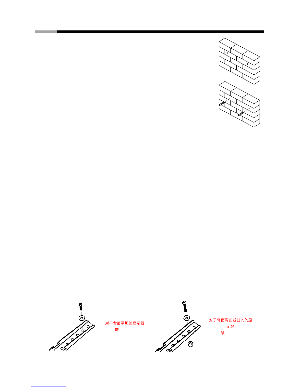
3. 8 mm 5/16"
4. C
5.
A B
2 -
!
:
1.
A. D F H
B. E G I
K
2. M4 M6 M8
-
3. 1 2
A. M4 M6 M6 J M8
B. K 1
Page 18

FIXED WALL MOUNT FOR LCD, PLASMA, and LED DISPLAYS RHTB-11003 User Manual
17
3 -
1.
2.
3. 6
4.
Page 19

FIXED WALL MOUNT FOR LCD, PLASMA, and LED DISPLAYS RHTB-11003 User Manual
18
26" 46"
45kg 100 lbs
400 mm x 400 mm 15.7" x 15.7"
2.8 cm (1.1 )
x1
x2
x1
x1
1.
2.
3.
4.
5.
6.
: 45 kg(100 lbs .
3 mm 1/8"
8 mm 5/16"
Page 20

FIXED WALL MOUNT FOR LCD, PLASMA, and LED DISPLAYS RHTB-11003 User Manual
19
(A) M6.3 x 63 x2
(G) M6 x 30
x4
(B) x2
(H) M8x 12
x4
(C) x2
(I) M8x 30 x4
(D) M4 x 12 x4
(J) M6 x4
(E) M4 x 30 x4
(K) x8
(F) M6 x 12 x4
1A -
!
16"
1.
2.
3.
4. 3 mm 1/8"
5.
M6.3 x 63 A
B
1B -
1.
2.
Page 21

FIXED WALL MOUNT FOR LCD, PLASMA, and LED DISPLAYS RHTB-11003 User Manual
20
3. 8 mm 5/16"
4. C
5.
A B
2 -
!
:
1.
A. D F H
B. E G I
K
2. M4 M6 M8
-
3. 1 2
A. M4 M6 M6 J M8
B. K 1
Page 22

FIXED WALL MOUNT FOR LCD, PLASMA, and LED DISPLAYS RHTB-11003 User Manual
21
3 -
5.
6.
7. 6
8.
Page 23

FIXED WALL MOUNT FOR LCD, PLASMA, and LED DISPLAYS RHTB-11003 User Manual
22
www.rosewill.com
 Loading...