

Page 1
FB-03/04
Page 2

1
© All rights reserved by Rosewill
User ManualFB-03/04
CASE
Contents
Opening Chassis
Installing Motherboard
Installing Power Supply
Disassemble Chart P.2
P.3
P.4
P.5
P.5
P.6
P.7
P.8
P.9
Accessory Box
Installing External 5.25"/3.5” Device
Installing 3.5” HDD
Installation Guide
Information
Product Overview
Installing Add-On Card
Installing 2.5” HDD/SSD
P.4
Closing Chassis
P.9
Page 3
2
© All rights reserved by Rosewill
User ManualFB-03/04
CASE
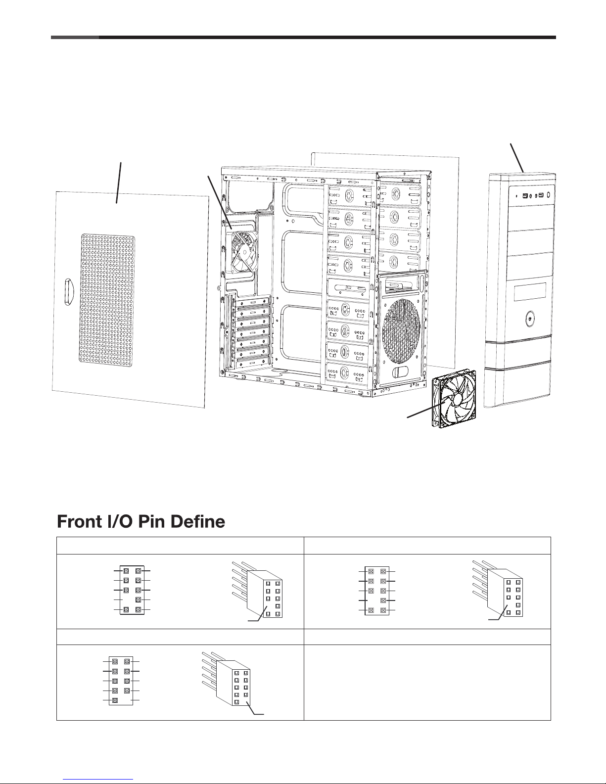
Disassemble Chart
Left side panel
( Please refer to your motherboard’s user’s manual to connect. )
USB2.0 CONNECTOR
HD CONNECTOR
AC97 CONNECTOR
USB+5V
LP
LP+
GND
NC
USB+5V
LP
LP+
GND
NO PIN
AUD GND
PRESENCE#
SENSE1 RETURN
NO PIN
SENSE2 RETURN
PORT1L
PORT1R
PORT2R
SENSE SEND
PORT2L
MIC
AUD GND
RET~R
NO PIN
RET~L
MIC
MIC~BIAA
FPOUT~R
+5V
FPOUT~L
NO PIN
NO PIN
NO PIN
( For reference only. Models’ option may be varied by countries. )
Front panel
80mm fan
120mm fan
Page 4
3
© All rights reserved by Rosewill
User ManualFB-03/04
CASE
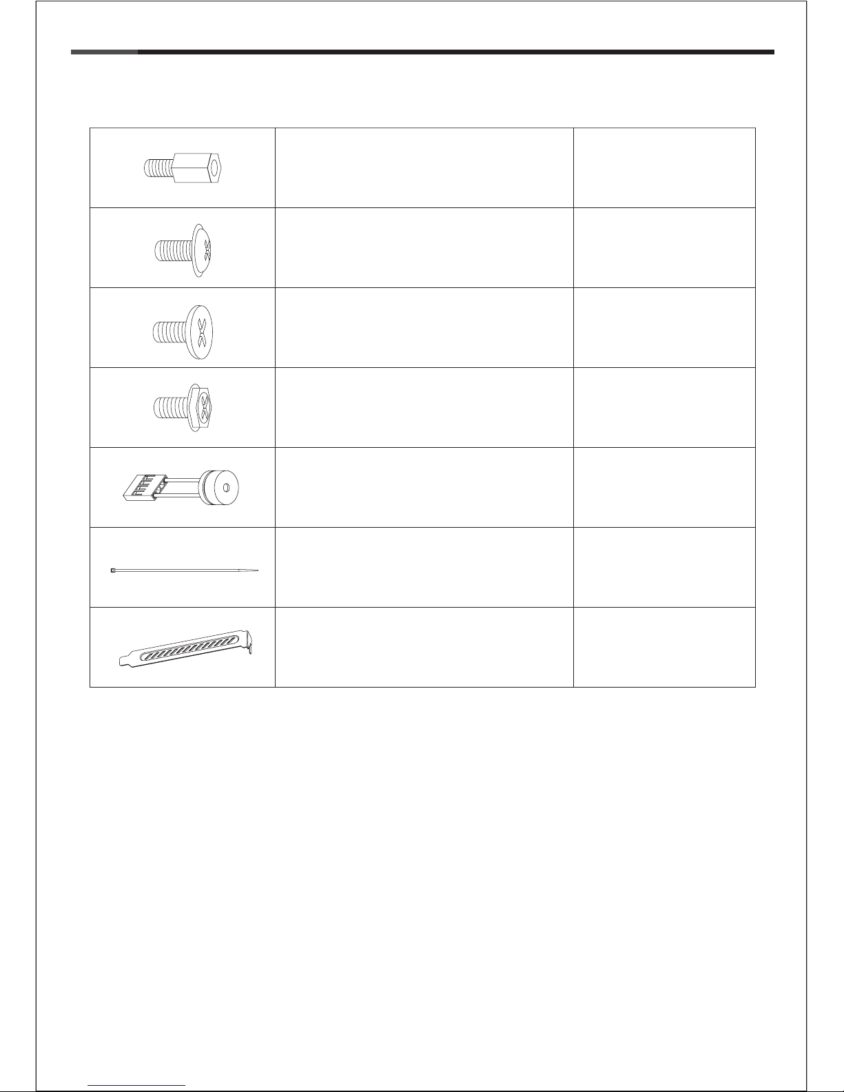
Accessory Box
9 x M/B standoff Motherboard
16 x screw-B 3.5” HDD
11 x screw-C
Power Supply
Add-on Card
29 x screw-A
Motherboard
1 x PC SPEAKER Motherboard
5 x Cable tie Cables
2 x PCI cover
Expansion Slot
2.5” SSD/HDD
5.25”/3.5” Device
Page 5

4
© All rights reserved by Rosewill
1. Opening Chassis
User ManualFB-03/04
CASE
Unscrew to remove left and right panels.
2. Installing 2.5” HDD/SSD
* screw-A
Place 2.5” HDD/SSD onto the bottom of the
chassis and secure with screws.
Page 6

5
© All rights reserved by Rosewill
4. Installing Motherboard
User ManualFB-03/04
CASE
Step 2- Place the motherboard onto stand-offs
and secure with screws.
NOTE : NOT every motherboard is made by standard,
please set stand-offs according to your motherboard.
* screw-A
Step 1- Install motherboard stand-offs according
to your motherboard’s form factor.
3. Installing Power Supply
Place the power supply from the left side into
the chassis and secure with screws.
NOTICE :
-If your power supply is equipped with single
fan (120mm, 135mm or 140mm), please have
the fan face to the bottom.
* screw-C
Page 7

6
© All rights reserved by Rosewill
User ManualFB-03/04
CASE
Step 4- Install add-on card and secure with screw.
Step 5- Close add-on card cover and secure with screw.
5. Installing Add-On card
1
2
3
4
5
Step 1- Unscrew add-on card cover.
Step 2- Release add-on card cover.
Step 3- Remove PCI slot cover.
*Screw C
Page 8

7
© All rights reserved by Rosewill
6. Installing External 5.25"/3.5” Device
7. Installing External 5.25"/3.5” Device
User ManualFB-03/04
CASE
Insert the external 5.25” & 3.5” device from the
front panel into the chassis then secure with
screws.
* screw-A
-Confirm which bay(s) you want to install
device(s) then remove the bay cover.
-Remove front panel by pulling from the bottom as shown.
Page 9

8
© All rights reserved by Rosewill
User ManualFB-03/04
CASE
* Screw-B
8.Installing 3.5” HDD
Place the 3.5” HDD into the HDD tray then secure with screws.
Page 10

9
© All rights reserved by Rosewill
User ManualFB-03/04
CASE
Thank you for purchasing a High-Quality Rosewill Product.
Please register your product at : http://www.rosewill.com
for complete warranty information and future support for your product.
If you have any question while using our products, please visit our website : www.rosewill.com
for latest driver & user manual or feel free to contact us.
Support Phone Number: 800-575-9885
Support Email: techsupport@rosewill.com
9. Closing Chassis
Make sure all necessary cables and
wires are connected, then reinstall
side panels and secure with screws.
Page 11

 Loading...