

Page 1

COOLER RCX-Z3
USER Manual
Page 2
Improper Installation will result in damage to the processor. Never
switch on the computer system until the fan is connected.
WARNING
!
COOLER RCX-Z3
User Manual
1
Features
.Six embedded 6mm full copper heatpipes with new heatpipe technology
provide rapid and even heat transfer.
.13mm full copper base and 52 hi-grade aluminum fins providing huge
surface ensure optimum cooling.
.Hi-air pressure of 67.9 CFM and 5.5mm H2O maximum air flow
delivered by 92mm hyper silence ball bearing fan
.Ultra quiet design for adjustable mode by fan controller:
Extremely silent Mode of 16.2 dB, maximum power Mode of 32.4dB
.Multi socket compatible of AMD Athlon 64 (754, 939, 940),
AM2 & Intel P4 LGA775
.Adjustable fan speed by supporting Intel PWM or you can control the fan
manually by the specially made bracket fan controller.
.Four bright blue LED embedded in stylish translucent fan duct.
Page 3
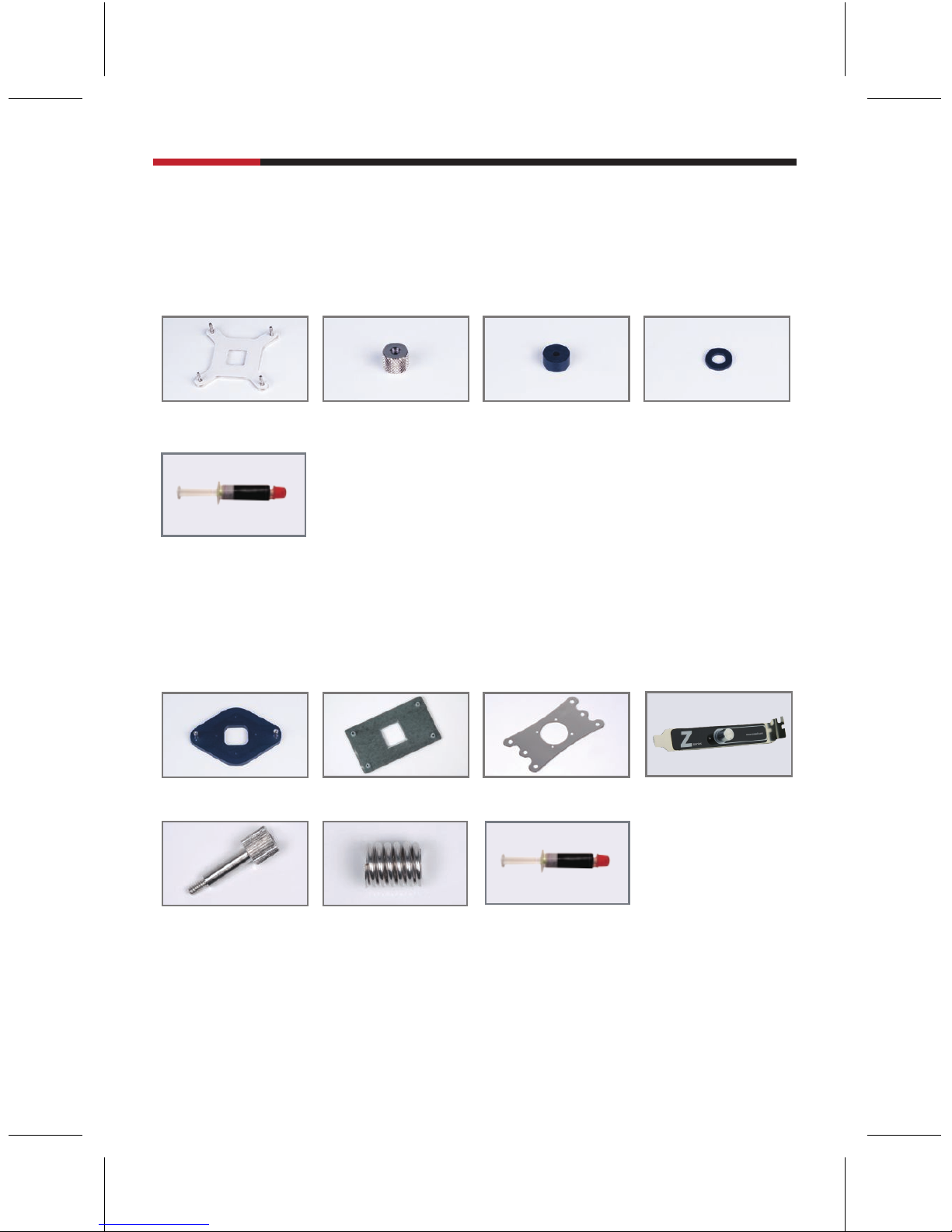
Installation Components
LGA775
(B) X 4pcs (C) X 4pcs (D) X 4pcs(A) X 1pcs
(N) X 1 pcs
AMD K8-AM2
(E) X 1pcs
(I) X 4pcs
(F) X 1pcs (G) X 1pcs (H) X 1pcs
(J) X 4pcs (N) X 1pcs
COOLER RCX-Z3
User Manual
2
Page 4
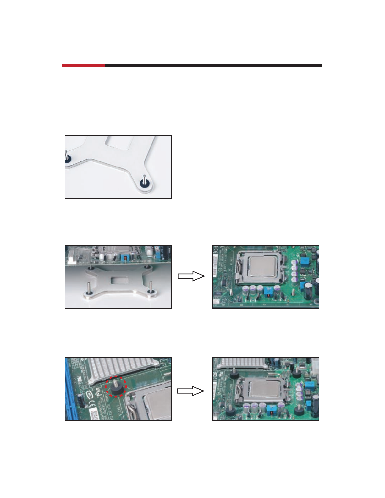
1. Place a rubber washer (part D) over each of the screws of the LGA775
backplate (part A).
2. Place the LGA775 backplate under the motherboard aligning the screws to fit
through the four holes available around the CPU as illustrated.
for LGA775
RCX-Z3
3. Place the thick rubber pads (part C) over each of the four (4) screws so they
sit on the motherboard as shown.
COOLER RCX-Z3
User Manual
3
Page 5

4. Apply the proper amount of thermal compound (part N) on the CPU surface;
a thin layer is ideal, extra thermal compound will not improve performance.
Make sure the CPU surface is perfectly clean.
5. Position the cooler over the four mounting screws. The installation direction
of the heatsink will depend on your case and its airflow requirements.
6. Secure the cooler with the collar nuts (part B), one for each screw, tighten
the nuts gradually in a crosswise manner.
COOLER RCX-Z3
User Manual
4
Page 6

8. Connect the 4-pin fan connector to the CPU fan motherboard connector. If a
connector marked CPU fan is not apparent on the board, check the
motherboard manual for fan connection information.
7. Connect the 2-pin female LED connector to the 2-pin male power connector
from the fan.
COOLER RCX-Z3
User Manual
5
Page 7

for AMD K8 / AM2
1. Take off the pre-attached LGA 775 heatsink retention bracket and retain the
four (4) screws for the next step.
2. Place the K8 heatsink retention bracket (part G) on the heatsink base
aligning the fixing screws with the Fan bracket indents and the corresponding
screw holes.
3. Secure the heatsink retention bracket with four (4) screws from step 1.
COOLER RCX-Z3
User Manual
6
Page 8

3. Apply the proper amount of thermal compound on the CPU surface; a thin
layer is ideal, extra thermal compound(part N) will not improve performance.
Make sure the CPU surface is perfectly clean.
Place the cooler on top of the CPU; align two spring loaded screws (part I +part J )
with the backplate standoffs and secure the cooler by tightening the screws.
for AMD K8
1. Remove the retention bracket from the motherboard by removing the screws
(or pins in some motherboards).
Note: It may be possible that the removal of the original backplate is not required if the cooler spring
loaded screws are compatible.
2. Place the backplate provided (Part E) below the motherboard aligning the two
standoffs with the holes in the motherboard as illustrated.
COOLER RCX-Z3
User Manual
7
Page 9

for AM2
1. Remove the retention bracket from the motherboard by removing the screws
(or pins in some motherboards).
Note: It may be possible that the removal of the original backplate is not required if the cooler spring
loaded screws are compatible.
2. Place the backplate provided (Part F) below the motherboard aligning the
four standoffs with the holes in the motherboard as illustrated.
3. Apply the proper amount of thermal compound on the CPU surface; a thin
layer is ideal, extra thermal compound will not improve performance. Make sure
the CPU surface is perfectly clean.
Place the cooler on top of the CPU; align four spring loaded screws (part I + part J)
with the backplate standoffs and secure the cooler by tightening the screws.
COOLER RCX-Z3
User Manual
8
Page 10

1. Connect the 2-pin female LED connector to the 2-pin male power connector
from the fan.
2. Connecting the fan:
A. Remove a PCI slot backplate and install the fan control unit (part H).
B. Connect the 4-pin fan connector to the male connector of the Y cable.
C. Connect the 3-pin female connector (with red / yellow / black wires) to the fan control.
D. Connect the 3-pin female connector (with yellow / black wires) to the CPU fan
motherboard connector.
E. Connect the fan control to the 4-pin PSU connector.
A B C
D E
for AMD K8 / AM2
COOLER RCX-Z3
User Manual
9
Thank you for purchasing a quality Rosewill Product.
Please register your product at : www.rosewill.com for complete warranty information
and future support for your product.
Page 11

www.rosewill.com
 Loading...