

Page 1

Page 2
CASE 6A series
User Manual
1
© 2004-2006 Rosewill Inc. All rights reserved by Rosewill
Contents
Configuration
Features Descriptions
Installation
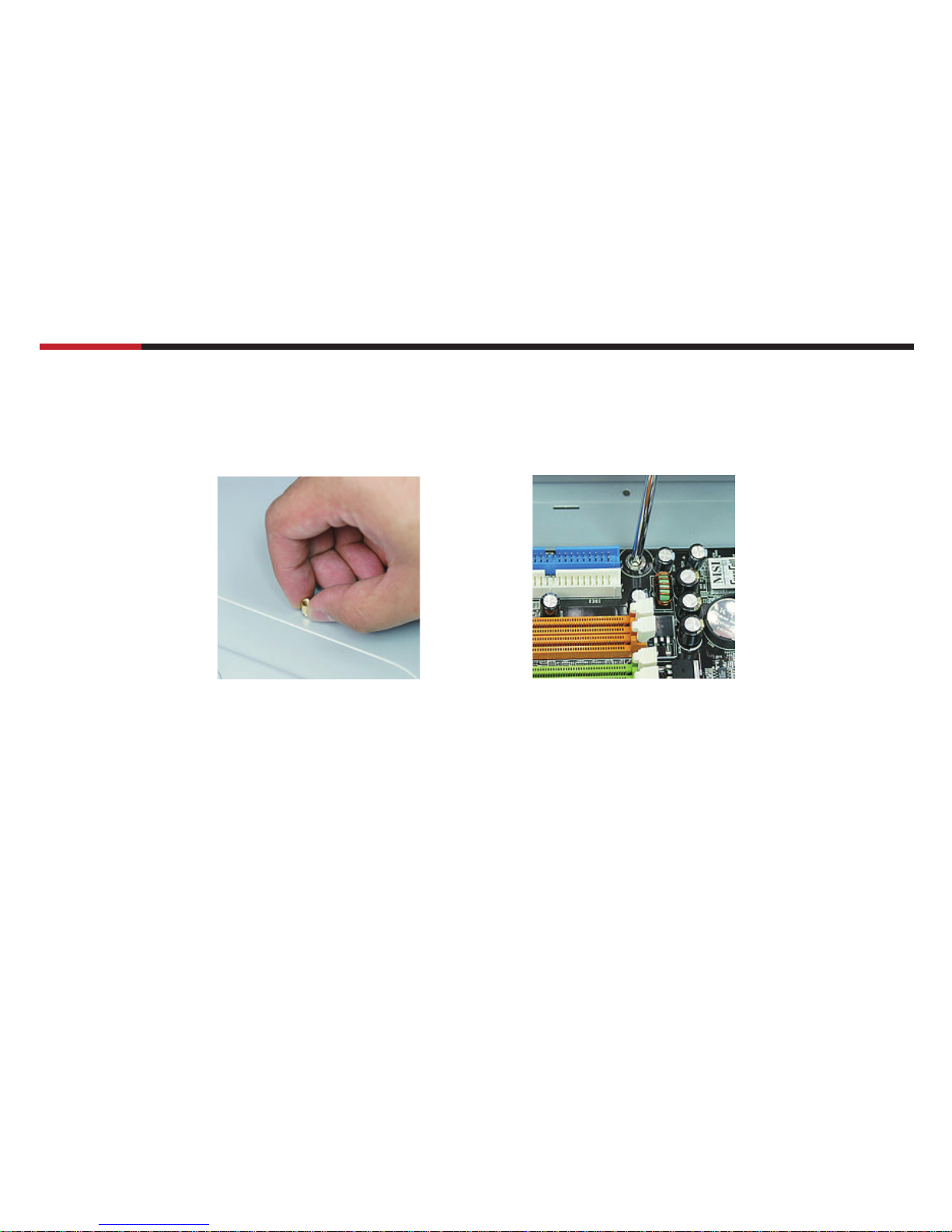
1.Opening Chassis
2.Installing Motherboard
3. Installing Power Supply
4.Installing 5.25" Device
5.Installing 3.5" Floppy
6.Installing 3.5" HDD
7.Installing Add on Card
9.USB port
10.Audio Port
P. 2
P. 3
P. 4
P. 5
P. 6
P. 7
P. 8
P. 9
P.10
P.12
P.13
11.Front Panel LED
P.14
12.System Control Connectors
P.15
Information
P.16
8.Clearing Air Filter
P.11
Page 3

CASE 6A series
User Manual
2
© 2004-2006 Rosewill Inc. All rights reserved by Rosewill
Confi guration
Dimension
(W x H x D )
M/B Size
Drive Bay
Expansion Slots
Thermal Solution
Air Filter
I/O Port Bracket
Megal Material
8.3" x 18.1" x 16.9"
ATX, Micro ATX
External : 4 x 5.25" + 2 x 3.5"
Internal : 5 x 3.5"
7Slots
1 x 120 mm fan in rear and 1 x 120 mm fan holder in front
One air fi lter in the front panel
Supports one I/O port bracket for standard ATX M/B
0.8 mm thickness SECC rustproof & galvanized JIS Steel
Page 4
CASE 6A series
User Manual
3
© 2004-2006 Rosewill Inc. All rights reserved by Rosewill
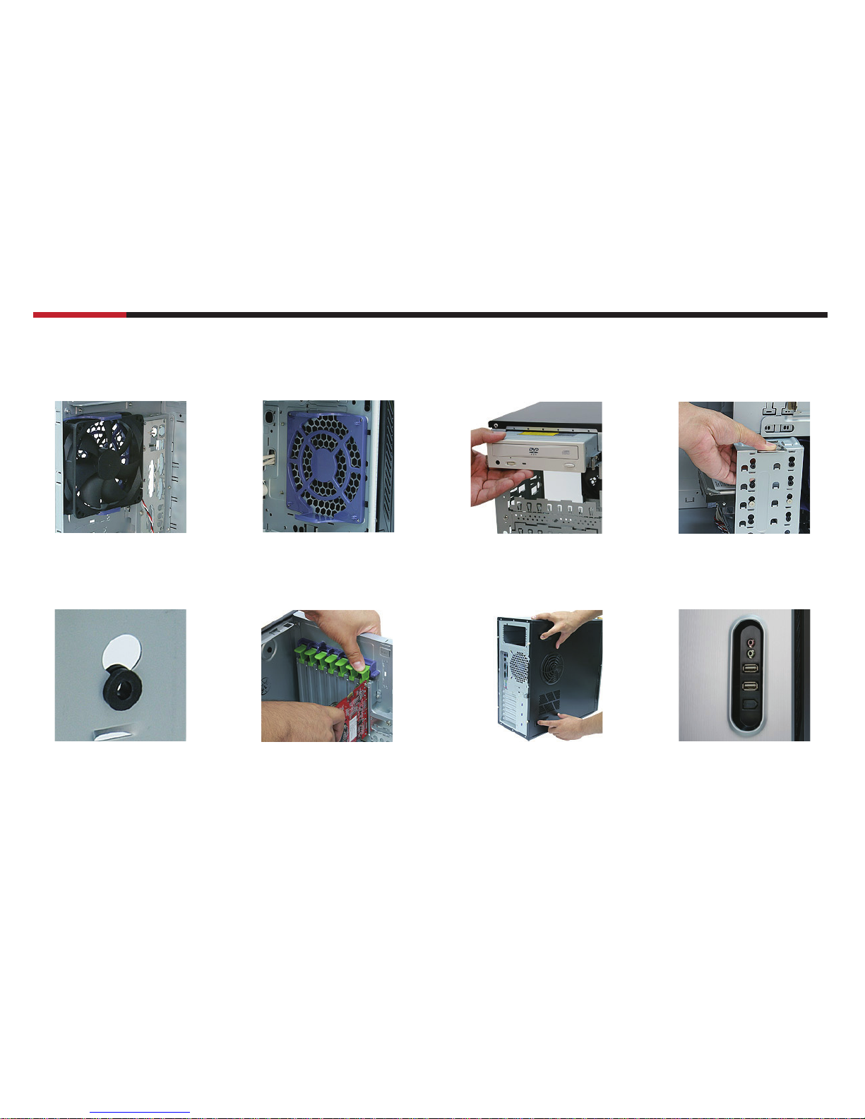
Features Descriptions
Rear 120mm Fan Front 120mm Fan Holder Sliding Rails for 5.25"
Device
Vertical sliding HDD cage
HDD cage with Shockproof
Rubber Pads
Add on Card Kit No Screw Neded to Secure
& Open the Left Side Panel
Front IO Ports
Page 5
Page 6
CASE 6A series
User Manual
5
© 2004-2006 Rosewill Inc. All rights reserved by Rosewill
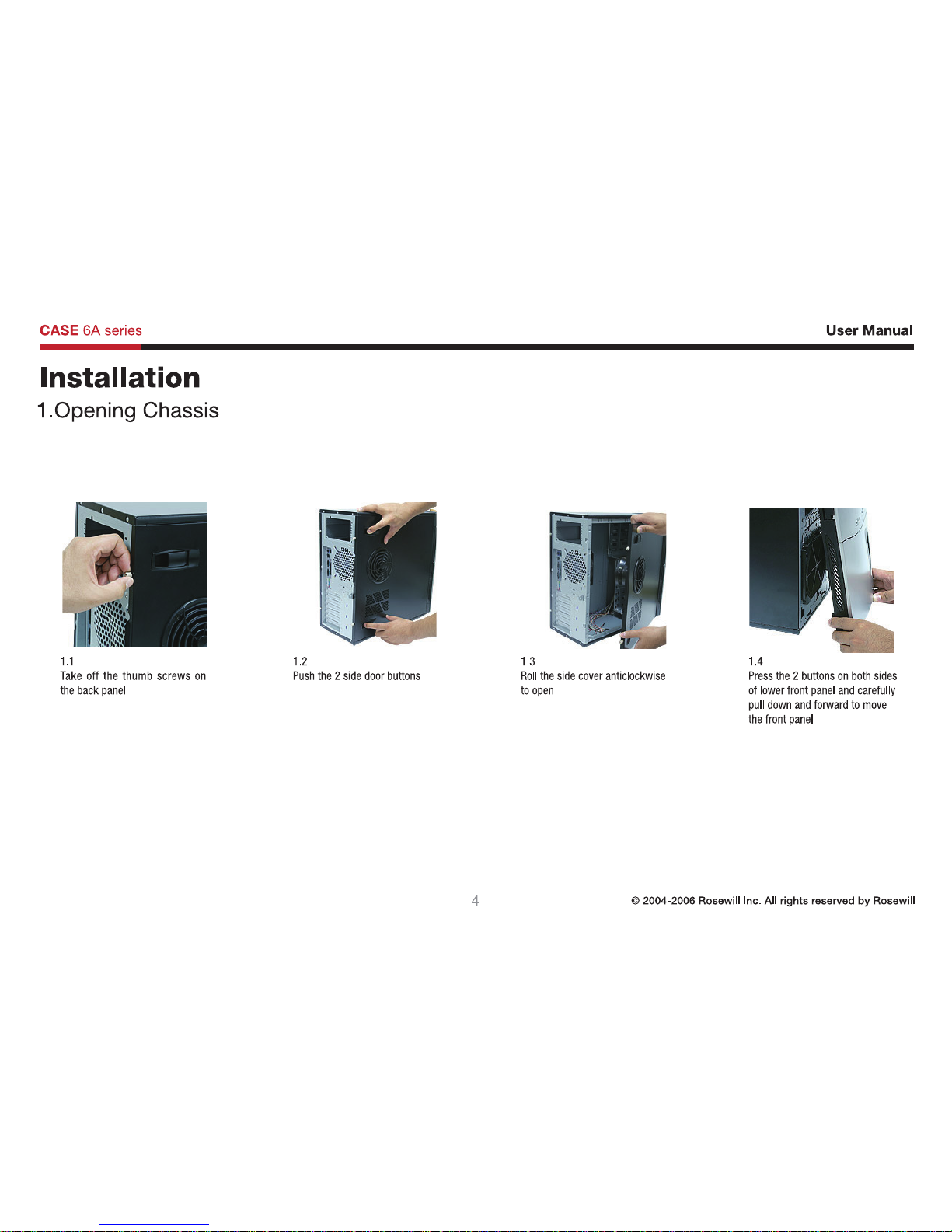
2.1
Locate and align the screw holes on the
motherboard and chasis; place the
motherboard at the correct position,
and then screw brass studs onto
chasis's metal shell
2.2
Secure the motherboard on the studs with
the screws #6-32
2.Installing Motherboard
Page 7

CASE 6A series
User Manual
6
© 2004-2006 Rosewill Inc. All rights reserved by Rosewill
3.1
Put your power supply in the right position and fasten screws from back panel of the case
3.Installing Power Supply
Page 8

CASE 6A series
User Manual
7
© 2004-2006 Rosewill Inc. All rights reserved by Rosewill
4.1
Locate the screw holes on both
sides of 5.25"device such as
CD-ROM and screw the rails
onto the 5.25" device
4.2
Insert the railed device into the
5.25" drive bay
4.Installing 5.25" Device
NOTE :
• Recommend to remove the 5.25" metal cover below the bay you
want to install your 5.25" device for easier installation
• When you feel diffi cult to pull out your railed 5.25" device, push it
down a little will help you
Page 9

CASE 6A series
User Manual
8
© 2004-2006 Rosewill Inc. All rights reserved by Rosewill
5.Installing 3.5" Floppy
5.2
Slide the fl oppy or, if necessary
HDD into the drive bay
5.4
Slide the small cage into drive
bay, make sure the cate is
properly positioned
5.1
Pull the handle and cage backwards to take off the small cage
5.3
Fasten the fl oppy on cage by
screws
Page 10

CASE 6A series
User Manual
9
© 2004-2006 Rosewill Inc. All rights reserved by Rosewill
6.Installing 3.5" HDD
6.2
Push the handle down and pull
the large cage out
6.4
Screw up and fasten HDD on the
cage
*Handle with care because
HDD is likely to be damaged by
careless management
6.1
Take off the thumb screw on the
large cage
6.3
Slide the HDD into the drive bay
6.5
Slide the large cage into drive
bay and fasten the thumb screws
Page 11
CASE 6A series
User Manual
10
© 2004-2006 Rosewill Inc. All rights reserved by Rosewill
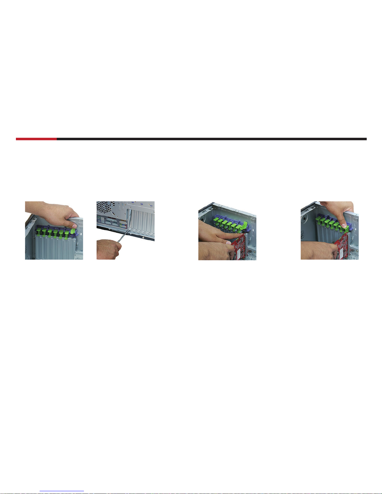
7.Installing Add on Card
7.3
Push down the kit to fasten the
add on card
7.1
Loosen the kit above the slot you want to install your add on card in and
remove the metal cover by your fl at screwdriver.
7.2
Insert your add on card into the
right slot
Page 12

CASE 6A series
User Manual
11
© 2004-2006 Rosewill Inc. All rights reserved by Rosewill
8.Clearing Air Filter
NOTE :
Some 6A models have the air filter in the front panel. Don’t have to work
previous steps. ( ex.R6AU6, R6AR6 )
8.1
Push the hooks marked in red circles.
8.2
Detach the air filter to clean.
R6AU6 R6AR6
Page 13

CASE 6A series
User Manual
12
© 2004-2006 Rosewill Inc. All rights reserved by Rosewill
9.USB Port
NOTE :
1.Make sure that your motherboard offers USB interface. NOT every motherboard offers it.
2.NEVER connect a IEEE1394 connector to the USB pins. It will damage the motherboard.
9.1 Read your motherboard’s user manual to find the pins for the USB connector.
9.2 Find the USB connector and connect it to the pins.
USB+5V
M/B USB PINS
USB_P5 -
USB_P5 +
GND
USB+5V
USB_P8 USB_P8 +
GND
ON
Page 14

CASE 6A series
User Manual
13
© 2004-2006 Rosewill Inc. All rights reserved by Rosewill
10.Audio Port
MIC2
MICPWR
Line out_R
NC
Line out_L
AGND
+5VA
Bline_out_R
Bline_out_L
NOTE :
Make sure that your motherboard offers Audio interface for front panel. NOT every motherboard offers it.
10.1 Read your motherboard’s user manual to find the pins for the Audio connector.
10.2 Find the Audio connector and connect it to the pins.
M/B Audio PINS
Page 15

Page 16
CASE 6A series
User Manual
15
© 2004-2006 Rosewill Inc. All rights reserved by Rosewill
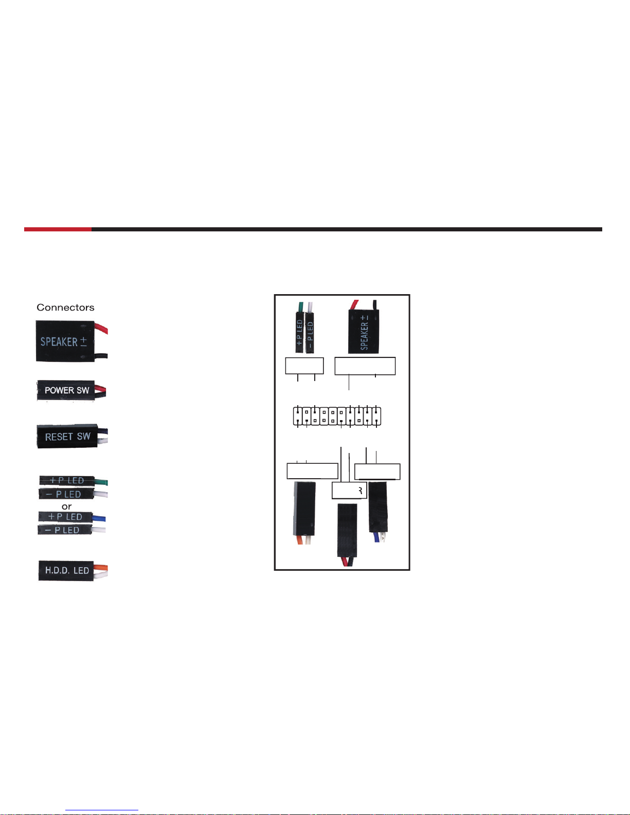
12.System Control Connectors
1. Read your motherboard’s user manual to find the pins for these system control connectors.
2. Refer to your motherboard’s user manual to connect these connectors correctly.
PLED+
PLED-
IDE_LED+
IDE_LED-
PWA
Ground
Reset
Ground
Ground
Ground
Speaker
+5V
PLED
PWR
RESETIDE_LED
SPEAKER
System Warning Speaker
ATTENTION :
The diagram is just an example.
NOT every motherboard has the same
layout of these system control pins.
Please refer to your motherboard
user’s manual to check the layout
before the installation.
Connectors
ATX Power Switch
Reset Switch
System Power LED
HDD Activity LED
or
Page 17

Page 18

www.rosewill.com
 Loading...