

Page 1

CASE 5600 Series
USER Manual
www.rosewill.com
Page 2
CASE 5600 series
User Manual
Contents
Configuration
Features Descriptions
Installation
1. Opening Chassis
2. Installing Motherboard
3. Installing 3.5" HDD
4. Installing 5.25" Device
5. Installing Add on Card
6. Installing Floppy
7. Cleaning Filters-Air guide Filter
8. Cleaning Filters-Front panel Filter
9. USB port
10. IEEE1394 Port
11. Audio Port
12. System Control Connectors
Information
P. 2
P. 3
P. 5
P. 6
P. 8
P. 9
P. 1 0
P. 1 1
P. 1 3
P. 1 3
P. 1 4
P. 1 5
P.16
P.17
P. 1 8
1
© 2004-2006 Rosewill Inc. All rights reserved by Rosewill
Page 3
CASE 5600 series
Confi guration
User Manual
Dimension
(W x H x D)
M/B Size
Drive Bay
Expansion Slots
Thermal Solution
Air Filter
I/O Port Bracket
Megal Material
7.9" x 17.3" x 19.4"
ATX, Micro ATX
External : 4 x 5.25" + 2 x 3.5"
Internal : 5 x 3.5"
7Slots
1 x 12 cm fan in rear and 1 x 12 cm fan holder in front
One air fi lter on the front panel ( only in R6A34)
Supports one I/O port bracket for standard ATX M/B
0.8 mm thickness SECC rustproof & galvanized JIS Steel
2
© 2004-2006 Rosewill Inc. All rights reserved by Rosewill
Page 4
CASE 5600 series
Features Descriptions
User Manual
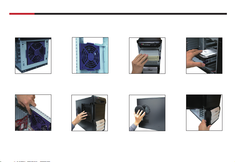
Front 120mm Fan Rear 120mm Fan Sliding Rails for 5.25"
Screw-less Add-on Card
assembly
Door opening up to 270
Degree
3
device
Easy-clean fi lter
(in left side panel)
Sliding Rails for 3.5" HDD
Easy-clean fi lter
(in front panel)
© 2004-2006 Rosewill Inc. All rights reserved by Rosewill
Page 5
CASE 5600 series
User Manual
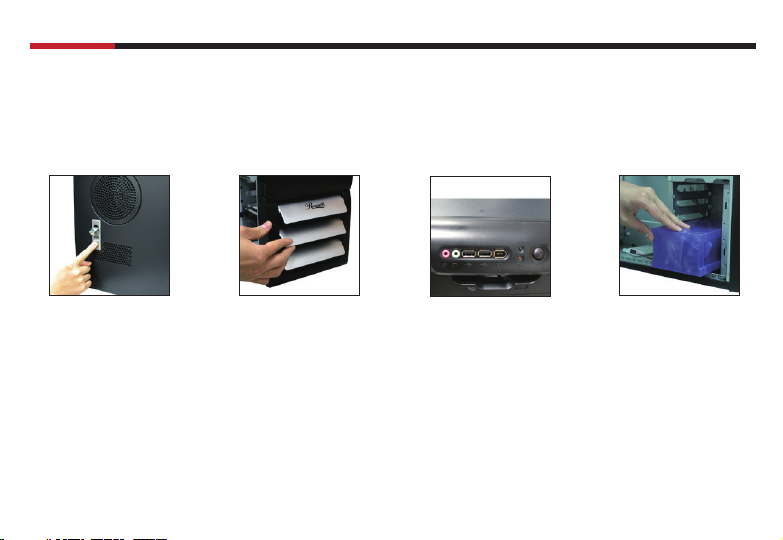
Screw-less and lockable
left side panel
Adjustable air inflow Front IO Ports Convenient Accessory box
4
© 2004-2006 Rosewill Inc. All rights reserved by Rosewill
Page 6
CASE 5600 series
Installation
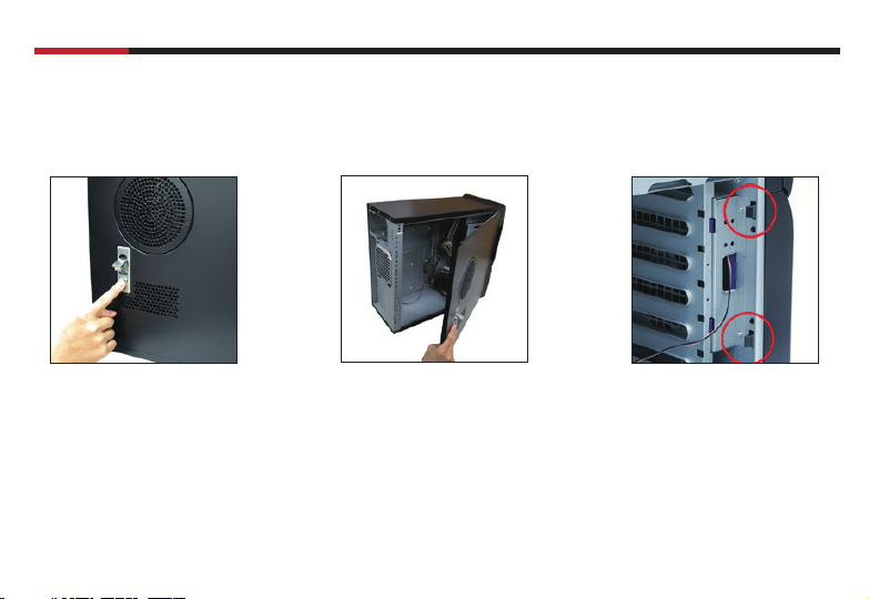
1.Opening Chassis
User Manual
1.1
Take off the thumb screws on the back plane
1.2
Push the Key-button
1.3
Roll the side cover anticlockwise to open
5
1.4
Push hooks marked in red circle to detach the
front panel from the chasis
© 2004-2006 Rosewill Inc. All rights reserved by Rosewill
Page 7

CASE 5600 series
2.Installing Motherboard
ATX Motherboard
Special motherboard stand-off
2.1
Due to our special design of
motherboard stand-off,copper
motherboard stand-off not needed
when you install the ATX motherboard.
NOTE : The copper motherboard stand-off not
needed when you install the ATX motherboard.
DON'T SCREW THE COPPER MOTHERBOARD
STAND-OFF INTO THE SPECIAL MOTHERBOARD
STAND-OFF OR MOTHERBOARD INSTALLING
CAN'T BE PROCESSED SUCCESSFULLY.
6
2.2
Sit the motherboard on our special
motherboard stand-off and screw in all the
screws into the motherboard stand-offs.
© 2004-2006 Rosewill Inc. All rights reserved by Rosewill
User Manual
Page 8

CASE 5600 series
Micro ATX Motherboard
User Manual
2.1
Locate and align the screw holes on the
motherboard and chasis; place the
motherboard at the correct position,
and then screw copper motherboard standoffs brass studs onto chassis's metal shell.
Note: Screw holes marked with "M" are
motherboard stand-off positions for micro
ATX motherboard.
2.2
Sit the motherboard on themotherboar
stand-offs and screw in all the screws
into the motherboard stand-offs.
7
© 2004-2006 Rosewill Inc. All rights reserved by Rosewill
Page 9

CASE 5600 series
3.Installing 3.5" HDD
User Manual
3.1
Insert the screw into the rubber pad hole on the rail
3.2
Attach rails to bothe sides of
your HDD
NOTE : Screws for HDD have no
thread, no screwdriver needed
when you work step 3.2
8
3.3
Insert the railed HDD into the 3.25" HDD bay and push to the buttom
© 2004-2006 Rosewill Inc. All rights reserved by Rosewill
Page 10

CASE 5600 series
4.Installing 5.25" Device
User Manual
4.1
Disassemble the front panel (please refer to step 1.4 )
4.2
Attach rails to both sides of your 5.25" device
PS: You can also fasten rails on your 5.25" device by screws
4.3
Insert the railed 5.25" device into the 5.25"
drive bay
9
© 2004-2006 Rosewill Inc. All rights reserved by Rosewill
Page 11

CASE 5600 series
5.Installing Add on Card
User Manual
5.1
Push out to loosen add on card kit
5.2
Insert your add on card into the right slot
10
5.3
Push down add on card kit to fasten the add
on card
© 2004-2006 Rosewill Inc. All rights reserved by Rosewill
Page 12

CASE 5600 series
6.Installing Floppy
User Manual
6.1
Detach the front panel
(Please refer to Step 1.4, Page 5)
6.2
Unscrew the screws holding the
fl oppy cage
11
6.3
Slide out the fl oppy cage
6.4
Remove the metal cover
© 2004-2006 Rosewill Inc. All rights reserved by Rosewill
Page 13

CASE 5600 series
User Manual
6.5
Secure the fl oppy on cage by
screws
6.6
Slide the fl oppy cage back
12
6.7
Secure the fl oppy cage by
screws
6.8
Attach the front panel
© 2004-2006 Rosewill Inc. All rights reserved by Rosewill
Page 14

CASE 5600 series
User Manual
7.Cleaning Filters - Air Guide Filter
7.1
Turn anticlockwise to take off the fi lter
8.Cleaning Filters - Front panel Filter
8.1
Push front panel hooks to detach
the front panel from the chassis
( please refer to step 1.4 )
13
© 2004-2006 Rosewill Inc. All rights reserved by Rosewill
8.2
Detach the fi lter from the front
panel
Page 15

CASE 5600 series
9.USB Port
NOTE :
1.Make sure that your motherboard offers USB interface. NOT every motherboard offers it.
2.NEVER connect a IEEE1394 connector to the USB pins. It will damage the motherboard.
9.1 Read your motherboard’s user manual to find the pins for the USB connector.
9.2 Find the USB connector and connect it to the pins.
M/B USB PINS
User Manual
USB+5V
USB_P5 -
USB_P5 +
GND
14
USB+5V
USB_P8 USB_P8 +
GND
ON
© 2004-2006 Rosewill Inc. All rights reserved by Rosewill
Page 16

CASE 5600 series
10.IEEE1394 Port
NOTE :
1.Make sure that your motherboard offers IEEE1394 interface. NOT every motherboard offers it.
2.NEVER connect a USB cable to the IEEE1394 connectors. It will damage the motherboard.
10.1 Read your motherboard’s user manual to find the pins for the IEEE1394 connector.
10.2 Find the IEEE1394 connector and connect it to the pins.
M/B IEEE1394 PINS
User Manual
TPA2+
GND
TPB2+
+12V
15
GND
+12V
TPB2
GND
TPA2
© 2004-2006 Rosewill Inc. All rights reserved by Rosewill
Page 17

CASE 5600 series
11.Audio Port
NOTE :
Make sure that your motherboard offers Audio interface for front panel. NOT every motherboard offers it.
10.1 Read your motherboard’s user manual to find the pins for the Audio connector.
10.2 Find the Audio connector and connect it to the pins.
M/B Audio PINS
MIC2
MICPWR
Line out_R
NC
Line out_L
AGND
+5VA
Bline_out_R
Bline_out_L
User Manual
16
© 2004-2006 Rosewill Inc. All rights reserved by Rosewill
Page 18

CASE 5600 series
12.System Control Connectors
1. Read your motherboard’s user manual to find the pins for these system control connectors.
2. Refer to your motherboard’s user manual to connect these connectors correctly.
Connectors
System Warning Speaker
SPEAKER
PLED
ATX Power Switch
Reset Switch
System Power LED
HDD Activity LED
PLED-
PLED+
IDE_LED-
IDE_LED+
PWA
PWR
+5V
Ground
Ground
RESETIDE_LED
Ground
Reset
Speaker
Ground
User Manual
ATTENTION :
The diagram is just an example.
NOT every motherboard has the same
layout of these system control pins.
Please refer to your motherboard
user’s manual to check the layout
before the installation.
17
© 2004-2006 Rosewill Inc. All rights reserved by Rosewill
Page 19

CASE 5600 series
Thank you for purchasing a High-Quality Rosewill Product.
Please register your product at : www.rosewill.com
for complete warranty information and future support for your product.
If you have any question while using our products, please visit our website : www.rosewill.com
for latest driver & user manual or feel free to contact us at feedback@rosewill.com
Support Phone Number: 800-575-9885
Support Email: techsupport@rosewill.com
User Manual
18
© 2004-2006 Rosewill Inc. All rights reserved by Rosewill
Page 20

www.rosewill.com
 Loading...