

BA 113 BB 10/12/A/SupraBox
BA113BB10/12/A/ SupraBox
Rosenberg Ventilatoren GmbH · Maybachstraße 1 · 74653 Künzelsau-Gaisbach
Tel.: +49(0)7940/142-0 · Fax.: +49(0)7940/142-125 · Email: info@rosenberg-gmbh.com · www.rosenberg-gmbh.com
EN
Betriebsanleitung
Operating instruction
SupraBox … D
SupraBox … D
Compact ventilation units
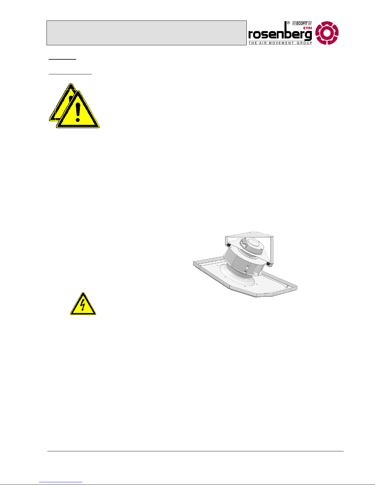
Series SupraBox COMFORT / Overhead version

Operation and Maintenance Manual for Rosenberg
Compact ventilation appliance series SupraBox Comfort
Overhead devices
BA 113 BB 10/12/A/SupraBox
1
Index Seite
1. General Safety Information ............................................................................................... 2
1.1 Warning regarding Health and Safety ............................................................................. 2
1.2 Safety Instruction ............................................................................................................ 3
2. Technical Manual ............................................................................................................... 4
2.1 General Description ........................................................................................................ 4
2.2 Device Overview ............................................................................................................. 5
2.3 Device drawings.............................................................................................................. 6
2.3 Device drawings.............................................................................................................. 7
3. Operating conditions ......................................................................................................... 9
4. Delivery, Transport and Storage .................................................................................... 10
4.1 Delivery ......................................................................................................................... 10
4.2 Transport ...................................................................................................................... 10
4.3 Storage ......................................................................................................................... 13
5. General Installation Instructions .................................................................................... 14
5.1 Installation of the unit .................................................................................................... 14
5.2 Assembly ...................................................................................................................... 14
5.3 Connection of the ventilation ducts to the unit .............................................................. 15
5.4 Electric Installation ........................................................................................................ 16
5.5 Connection of the condensate, exhaust air and overflow pipes .................................... 16
6. Startup and Operation ..................................................................................................... 17
6.1 General startup information .......................................................................................... 17
7. Maintenance and Cleaning .............................................................................................. 18
7.1 General Maintenance Instructions ................................................................................ 18
7.2 General Cleaning Instructions ....................................................................................... 18
7.3 Maintenance and Cleaning of the housing and control ................................................. 19
7.4 Fans .............................................................................................................................. 20
7.4.1 Initiation .................................................................................................................. 20
7.4.2 Use ......................................................................................................................... 22
7.4.3 Maintenance and Cleaning ..................................................................................... 22
7.5 Reverse flow heat exchanger ....................................................................................... 23
7.5.1 Startup .................................................................................................................... 23
7.5.2 Operation ................................................................................................................ 23
7.5.3 Maintenance and Cleaning ..................................................................................... 24
7.6 Panel filters ................................................................................................................... 26
7.6.1 Startup .................................................................................................................... 26
7.6.2 Operation ................................................................................................................ 26
7.6.3 Maintenance and Cleaning ..................................................................................... 26
Operation and Maintenance Manual for Rosenberg
Compact ventilation appliance series SupraBox Comfort
Overhead devices
BA 113 BB 10/12/A/SupraBox
2
1. General Safety Information
1.1 Warning regarding Health and Safety
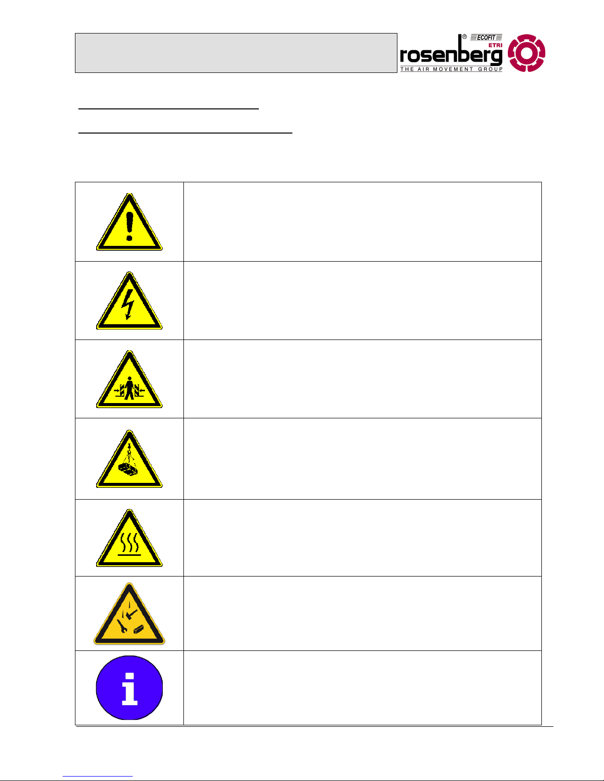
The following icons inform about certain hazards or safe use.
Attention! Danger! Safety Advice!
Hazard by electricity or high voltage!
Crush hazard!
Danger Overhead Hazard!
Caution ! Hot surface
Beware of falling objects
Important Advice, Information

Operation and Maintenance Manual for Rosenberg
Compact ventilation appliance series SupraBox Comfort
Overhead devices
BA 113 BB 10/12/A/SupraBox
3
1.2 Safety Instruction
At the time of delivery the Rosenberg SupraBox Comfort series is constructed and
produced according to the latest technical standard. Substantial tests of material,
function and quality guarantee a high value and a long lifetime. When improperly
used by untrained staff or not according to the instructions these machines can be
dangerous.
Read these instructions carefully prior to unpacking, assembling or performing
maintenance!
•
The system may only be used after installation.
• The following work must only be performed by trained specialists:
- Assembly
- Electrical connection
- Connection of power terminals
- Maintenance work
• Please use the compact ventilation appliance only according to the regulations within the
prescribed power limit. The power limit is included in the technical data specification or can be
found on the name plate. One single instance of the prescribed power limit being exceeded
will inevitably cause damage to the built-in components which results in the safe use of the
appliance being compromised.
• Only approved material handling equipment may be used. Please consult your local
institutions or relevant regulations for the appropriate range.
• Prior to working on electric machines these have to be disconnected from all poles
(padlockable selector switches with appropriate capacity and function are included in the
delivery and pre-installed).
• Service and maintenance operations must be performed only with appropriate protective
clothing and safety helmets, as these operations are overhead work.
• After completion of work on the RLT-appliance the responsible person must ensure that
nobody is working on the installation before it is re-started.
• Authorized persons must be instructed according to the normal accident prevention
regulations of the corresponding
Employer's Liability Insurance Associations and be trained in
their work area
.
Read also:
BGV A1 „General Instructions“
VBG 5 „Power-driven work equipment“
VBG 9a „Load bearing quipment for hoist operations“
BGV D27 „Industrial trucks“
BGV A3 „Electrical systems and equipment“

Operation and Maintenance Manual for Rosenberg
Compact ventilation appliance series SupraBox Comfort
Overhead devices
BA 113 BB 10/12/A/SupraBox
4
2. Technical Manual
2.1 General Description
• According to the EC Machinery Directive, stationery ventilation appliances have to be
electrically connected to a breaker and series fuse. It must be possible to disconnect the unit
from all poles!
• The unit corresponds to the requirements of VDI 6022 and DIN 1946 T6.
• Depending on the size of the installation the range of application extends to a power volume of
1.900 m³/h with 250 Pa ext. pressure and a maximum flow medium density of 1,3 kg/m³.
• The application area includes the air treatments: filtration, heating, cooling, and moving. In
addition heat recovery with high efficiency is used.
• Energy-efficient compact ventilation unit. Heat recovery through an aluminium reverse flow
recuperator with very high efficiency. It can be dismantled for cleaning and condensate will be
dissipated in a condensate pan with gradient all around.
• Unit is ready/prepared for connection to isolation/drop rod by the customer.
• The compact housing consists of corrosion-resistant, double skin, coil coated and galvanised
sheet steel; quality: DX51D + zinc 275 + additional org. coating min. 25 µm RAL 7035; metal
gauge 1.00 mm.
• Sidewall panels, housing bottom, housing cover, rear panel and doors (with double skin) are
equipped with 40 mm internal acoustic and heat insulation (min. 33 kg/m³;
λ = 0,04 W/m x K).
• The direct drive fans with backward curved centrifugal impellers are installed with vibration
absorption. The drive will be effected by two energy-saving and 100% infinitely variable ECmotors.
• Filtration of external air F7 and exit air F5 through particulate panel filters.
• The ventilation unit will be delivered with integrated control. This is easy to maintain and
installed in a terminal box on the sidewall of the housing. It is completely wired and tested by
the manufacturer.
• The unit is clearly labelled with symbols and text for easy operation. An external controller for
the managing the whole system is included.
Operation and Maintenance Manual for Rosenberg
Compact ventilation appliance series SupraBox Comfort
Overhead devices
BA 113 BB 10/12/A/SupraBox
5
2.2 Device Overview
SupraBox Comfort 1100 D 1900 D
Housing
Double skin 40 mm
frameless
Double skin 40 mm
frameless
Size
(L x W x H)
1755 x 1292 x 440 [mm]
Incl. Regulation box
and connection branch
1600 x 1892 x 440 [mm]
Incl. Regulation box
Operating Point
1100 m³/h at
200 Pa
1900 m³/h at
250 Pa
Fans
Backward curved, free running, driven by highly efficient Rosenberg – EC-external
rotor motors with integrated electronics
Power Input
In the operating point
2 x 320 W 2 x 750 W
SFP-Value
In the operating point
1048 Ws/m³ 1421 Ws/m³
SFP class
In the operating point
SFP2 SFP3
Heat recovery
Efficiency
Reverse flow -plate heat exchanger up to η=92%*, corresponding to WRG-classes
H1
*Maximum value on condensation; Heat recovery dependant on the operating
condition
Air filter
Panel filter with plastic frames incoming air: F7 extracted air: F5
358x553x96 [mm] 358x848x96 [mm]
Air Supplies
horizontal
DN 315
horizontal
330 x 480 [mm]
Control
Incoming air/extracted air/room temperature control, Fans 3-steps, steps adjustable
Bypass-function modulating 0 – 10V with anti-freezing monitoring
Activation of optional equipment according to size and facilities
Max. total current
consumption
4 A 9 A
Overall sound power
level
Suction side L
WA5
pressure side L
WA6
Housing L
WA2
60 dB(A)
80 dB(A)
53 dB(A)
64 dB(A)
87 dB(A)
63 dB(A)
Weight incl. control
188 kg 270 kg

Operation and Maintenance Manual for Rosenberg
Compact ventilation appliance series SupraBox Comfort
Overhead devices
BA 113 BB 10/12/A/SupraBox
6
1 Panel filter exhaust air F5 7 Loops/ transport loops
2 Reverse flow heat exchanger 8 Control box incl. control system
3 Bypass flap 9 Supply fan with EC-motor
4 Condensate pan
5 Panel filter incoming air F7
6 Exhaust fan with EC-motor
23
4
5
Ext.air
Exh
. air
Inc. air
Exh. air
1
7
8
6
9
Picture:drawing of the device overview
SB110DGRIB00

Operation and Maintenance Manual for Rosenberg
Compact ventilation appliance series SupraBox Comfort
Overhead devices
BA 113 BB 10/12/A/SupraBox
7
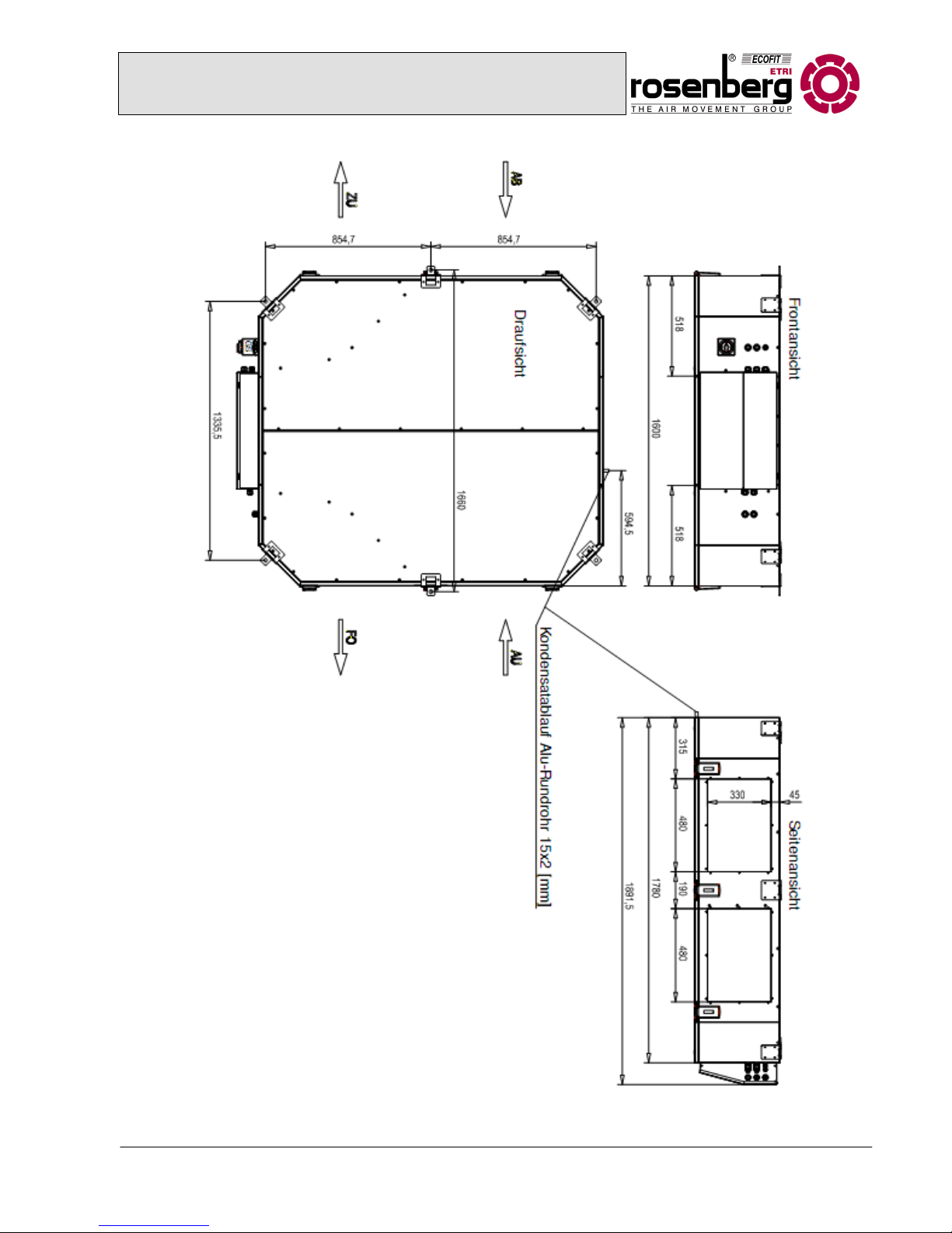
2.3 Device drawings
Suprabox 1100 D (SB110DGRIB00)
•
A hose with appropriate hose sleeve is recommended for the
condensate drain
Operation and Maintenance Manual for Rosenberg
Compact ventilation appliance series SupraBox Comfort
Overhead devices
BA 113 BB 10/12/A/SupraBox
8
Suprabox 1900 D (SB190DGRIB00)
•
A hose with appropriate hose sleeve is recommended for the
c
ondensate drain

Operation and Maintenance Manual for Rosenberg
Compact ventilation appliance series SupraBox Comfort
Overhead devices
BA 113 BB 10/12/A/SupraBox
9
3. Operating conditions
The Rosenberg compact series SupraBox Comfort is exclusively made for treating air
or gaseous media according to the criteria stated below!
The compact ventilation appliance is suitable for the conveyance of:
• Clean air, low dust air or low greasy air
• Slightly aggressive gases or fumes (consult the factory in either case!)
• Gaseous media up to a density of 1,3 kg/m³
• Gaseous media up to a relative humidity of max. 95%
• Gaseous media in a temperature range of –16°C to +40°C. (higher or lower ranges require
special modifications!)
• Non-explosive gaseous media

Operation and Maintenance Manual for Rosenberg
Compact ventilation appliance series SupraBox Comfort
Overhead devices
BA 113 BB 10/12/A/SupraBox
10
H
W
L
Picture: transport dimensions Suprabox
4. Delivery, Transport and Storage
4.1 Delivery
Rosenberg-Supraboxes must be checked for damages immediately on delivery. This
should be made before unloading the device from the transport vehicle. Furthermore
the completeness of the delivery scope must be checked in accordance with the
freight documents. Missing parts or damages must be noted immediately on the
freight documents and signed by the driver of the transport vehicle.
4.2 Transport
The unit will be delivered on a customized single use pallet and can be moved with a forklift or a pallet
truck. The transport dimensions (incl. control box) and weights can be found on the drawing below:
Suprabox L W H Weight
1100 D 1900 mm 600 mm 1460 mm 205 kg

Operation and Maintenance Manual for Rosenberg
Compact ventilation appliance series SupraBox Comfort
Overhead devices
BA 113 BB 10/12/A/SupraBox
11
H
L
W
Picture:: transport dimensions Suprabox
• Avoid twisting, bending or other physical damages of the housing when
hoisting the device!
• Keep the control doors closed during transport!
• Always use proper hoisting machines!
• Please note that excessive loads on the housing may cause damages!
• For your own safety use appropriate anti-slip gloves and safety shoes for the transport.
For the transport with forklift or pallet truck please note the following instructions:
• The transport with industrial trucks requires regular training of the
responsible staff according to the accident prevention regulation (in
Germany BGV D27 „Flurförderfahrzeuge“).
• The loading capacity of the material handling equipment must always be
checked before loading!
• The fork length of the material handling equipment must be greater than the length of the
transport pallet to be picked up. Forks which are too short cause damage to the floor panels.
Suprabox L W H Weight
1900 D 1800 mm 2000 mm 600 mm 315 kg

Operation and Maintenance Manual for Rosenberg
Compact ventilation appliance series SupraBox Comfort
Overhead devices
BA 113 BB 10/12/A/SupraBox
12
Heavy load
niedrige Belastung
For the transport with a hall crane or a truck crane please note the following instructions:
• The transport with cranes or lifting fixation devices requires regular
training of the responsible person according to the accident prevention
regulation (in Germany VBG 9a „Lastaufnahmeeinrichtungen im
Hebezeugbetrieb“)
• Danger Overhead hazard! It is forbidden to stay below floating loads!
• For direct load attachment (underdragging the load) only use exclusively licensed, undamaged
fabric slings with sufficient contact surface and edge protection. (e.g.: webbing slings
according to EN1492-1 or round slings according to EN1492-2)
• It is forbidden to use chain slings or slinging ropes for the direct load attachment!
• The slings should not have an inclination angle of more than 60°!
• Please note
that when lifting the
distribution of the functional part
is usually out of balance! This is not
visible from the outside of the
functional part!
Inclination angle
greater than 60°
Inclination angle
smaller than 60°
Picture:: Transport by crane
Picture: Unloading by forklift

Operation and Maintenance Manual for Rosenberg
Compact ventilation appliance series SupraBox Comfort
Overhead devices
BA 113 BB 10/12/A/SupraBox
13
Picture: Load distribution
Heavy load
Low load
• Only use carrying devices with the same length.
• Make careful and none jolting movements.
• Avoid setting the load down hard and bumping.
4.3 Storage
•
Make sure to store the unit in a dry and weather protected area!
• On receipt of the merchandise the packaging, film and tape must
immediately be removed in order to avoid condensation!
• Open pallets must be covered by tarps. Protect the functional parts against
pollution (e.g. chips, stones, wires etc.).
• Keep the storage temperature between -16°C and +40°C, avoid high humidity.
• If storing the unit for more than 12 months make sure the fan turns freely before installation.
►
Manual rotation of the rotor

Operation and Maintenance Manual for Rosenberg
Compact ventilation appliance series SupraBox Comfort
Overhead devices
BA 113 BB 10/12/A/SupraBox
14
5. General Installation Instructions
5.1 Installation of the unit
The Rosenberg-SupraBox Comfort overhead version must be installed on a ceiling
which is professionally constructed and statically suitable for this specific use.
Assumption of static or dynamic building functions by Rosenberg devices must be
excluded. Otherwise the warranty by Rosenberg Ventilatoren GmbH will expire for
damages to the device or resulting damages to the building.
Installation and assembly may only be made by trained staff, familiar with the specific accident
prevention regulations and general safety-related and occupational health laws.
In addition to the static analysis for the overhead construction also consider the following instructions:
• The suspension must be level and without torsion.
• The horizontal inclination angle of the device may not exceed a maximum of 2%.
• Choose an installation space with an unobstructed condensate drain and water trap, as well
as a sufficient gradient of the condensate line.
• The height level between installation space and the floor/intermediate ceiling must guarantee
a professional condensate drain from the functional parts.
► Consider the height of the waste trap!
In order to ensure low noise operation consider the following advice:
• Low air velocity in the duct
• Do not install the device on a wooden ceiling
• Use a vibration resistant ceiling construction
5.2 Assembly
Get an overview of the quantity and description of all functional parts with help of the
enclosed technical documents. Under item 2.2 unit overview or 2.3 unit drawing
respectively there is a detailed drawing with all relevant dimensions.
For an installation of the SupraBox in the intermediate ceiling or the area of
operation respectively the inspection opening and space to the floor must be big
enough for maintenance and revision. Permanent access must be guaranteed.
Operation and Maintenance Manual for Rosenberg
Compact ventilation appliance series SupraBox Comfort
Overhead devices
BA 113 BB 10/12/A/SupraBox
15
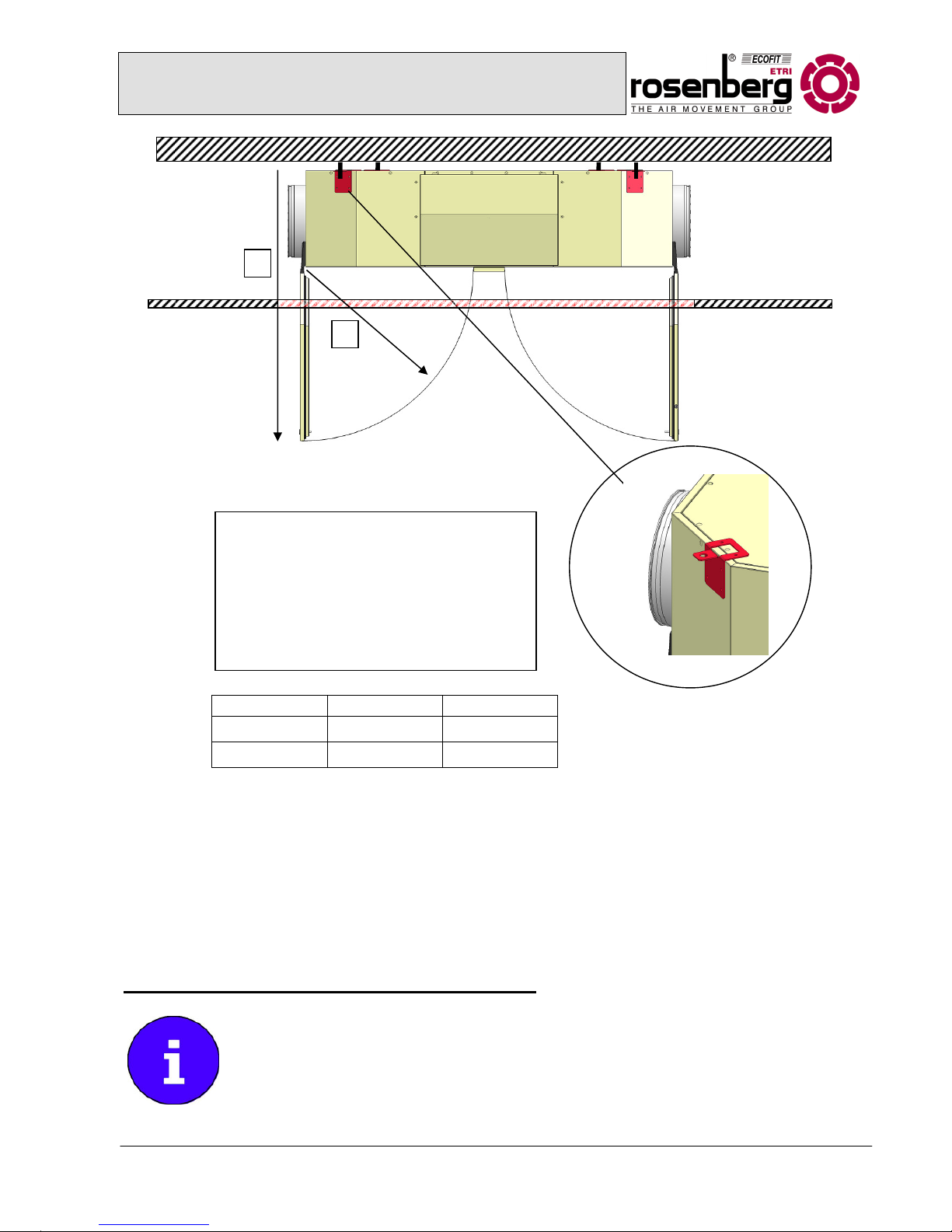
Picture: revision area
R
T
It is important to have sufficient space for
operating and maintaining the unit underneath
the suspended Suprabox. The condensate
drain connection installed by the customer
must be removed before opening the exhaust
air door. The device must be fixed at the
loops/transport loops.
The compact ventilation appliance will be completely wired for plug-in and checked by the
manufacturer. They are equipped with an integrated control system.
Only the connections for the ventilation ducts, the condensate and water must be properly installed on
site. Furthermore the electrical supply as well as external sensors or optional accessories such as
duct heaters etc. must be connected.
The remote operator control must be connected to the control system using the provided cable and
placed at the ventilation unit or nearby. The electrical connection has to be made according to the
wiring diagram, see the additional operating manual for the control system.
5.3 Connection of the ventilation ducts to the unit
The connection sleeves of the Rosenberg-SupraBox Comfort overhead versions are
provided as circular tube spigots, with T-sealing lip (1100D) or as rectangular
connection (1900D), sizes as shown in the unit drawings. The duct system must be
installed according to the valid technical standards and regulations and must support
the dead load by installations of the customer. Additional requirements concerning
Suprabox R [mm] T [mm]
1100 D 520 960
1900 D 520 960
Operation and Maintenance Manual for Rosenberg
Compact ventilation appliance series SupraBox Comfort
Overhead devices
BA 113 BB 10/12/A/SupraBox
16
sound insulation can be met by separate vibration isolation with elastic connections. These are
usually not included in the delivery, but can be provided as additional equipment. The external air and
exhaust air duct must be protected against condensate water.
5.4 Electric Installation
The electric connection must be exclusively made by a licensed electrician according
to the VDE-regulations. The connection must be made exactly according to the wire
diagram and face plan.
Check all screw joints before startup of the unit and if necessary retighten them.
Further installation information can be found in the separate operating manual of the
control system.
5.5 Connection of the condensate, exhaust air and overflow pipes
The Suprabox is equipped with a condensate pan including an all-side gradient in the exhaust air. The
condensate drain consists of an aluminium circular tube of 15 x 2 mm. To ensure that the exhaust air
maintenance door can be opened, we recommend an appropriate flexible hose with a circular cuff for
connection.
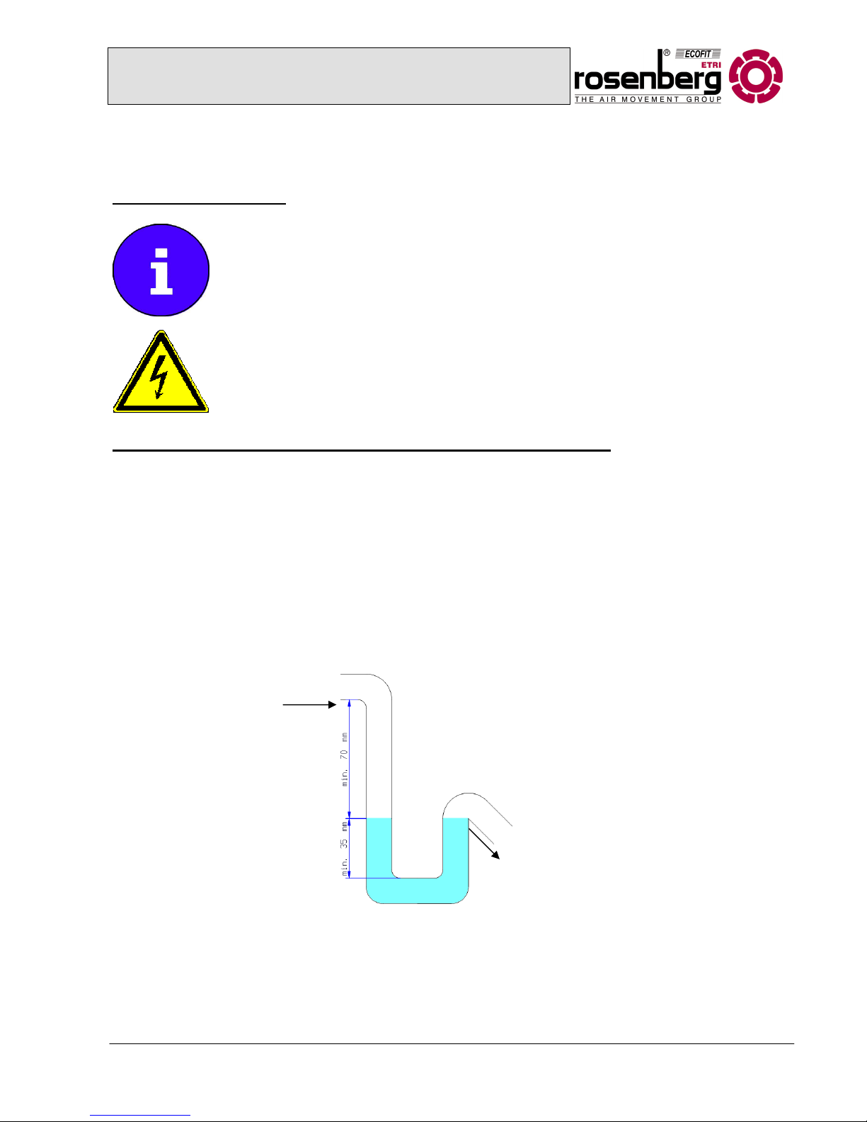
Especially in the cold seasons there could be condensate in the exhaust air duct of the reverse flow
heat exchanger. In order to make sure the condensate drains correctly via the condensate pan and to
avoid air leakage it is important to attach a vacuum trap. Alternatively a hose can be fixed at the unit
to replace a trap. The minimum size must be observed by the customer. Fill the trap with water before
startup. Protect the trap against desiccation and in cold areas against frost. Do not connect the spout
to the sewage system. Alternatively a vacuum trap with non-return ball can be used but make sure
that there is a suction lift of at least 70 mm.
Picture: minimum size trap
Unit Connectio

Operation and Maintenance Manual for Rosenberg
Compact ventilation appliance series SupraBox Comfort
Overhead devices
BA 113 BB 10/12/A/SupraBox
17
6. Startup and Operation
6.1 General startup information
Prior to the startup of the compact ventilation unit observe the instructions below:
• Inspection of the proper installation, connection and assembly
• Free air connection, free suction holes
• Free running of the fan wheels
• Closed valves at the heat exchanger units
• Check the screw joints of all connections
• Unlock the electric duct heater only after the fan
• Remove a possible protective film
• Optical inspection of the unit gaskets for damage
• Re-adjust the hinges of the maintenance doors
• Close all doors
• Operational check of the fans
• Pressure control of the reverse flow heat exchanger must be set according to the operating
point of the unit.
► Attention: If the above instructions are not followed, dangerous conditions
may occur on startup of the unit, which affect the functionality and safety of
the unit.
►ATTENTION: Before stopping the unit de-energize it and
remove water of optional heaters to avoid freezing.
Further information for the startup of the units can be found in the corresponding component
specification beginning with item 7.4.The instruction manual of the control system must absolutely be
observed!
Operation and Maintenance Manual for Rosenberg
Compact ventilation appliance series SupraBox Comfort
Overhead devices
BA 113 BB 10/12/A/SupraBox
18
7. Maintenance and Cleaning
7.1 General Maintenance Instructions
The maintenance interval indicated in this manual basically refers to the transport of
normally polluted air. If the unit must transport strongly polluted air the maintenance
intervals must be reduced accordingly.
►
Before any maintenance work is started the unit must be stopped properly and all
poles disconnected from the mains. Proceed in the following order.
1. Stop the unit using the remote operator. Activated full automatic weekly
programs have to be deactivated first.
2. Wait 2 minutes until the optional louver damper is closed and the fans have
stopped.
3. Now turn the operating switch to ZERO (Off) and make sure that it will not be
switched on unintentionally. This step disconnects the compact unit from the
mains with all poles. Be aware that the control box will still be hot. For
maintenance at the control box the connection must be interrupted.
4. Wait for the residual voltage to decrease at the EC-control as
indicated in the instruction manual of those components.
5. Let the heater cool down.
6. Now you can open the maintenance doors.
Pay attention that at optionally used channel-type heat exchangers the water circulation is protected
against re-starting.
7.2 General Cleaning Instructions
Recommended cleaning agents for surface disinfection are:
• Dismozon pur (Bode Chemie)
• Melsitt (B.Braun)
• Antifect (Schülke & Mayr)
• Clorina (Lysoform)
All disinfectants are recognized and licensed by Robert-Koch-Institute (date 31.05.2007, 15. edition)
To ensure the hygienically perfect condition of the unit the following instructions must be observed:
• Only qualified and trained staff should clean the unit (in Germany according to VDI 6022).
Operation and Maintenance Manual for Rosenberg
Compact ventilation appliance series SupraBox Comfort
Overhead devices
BA 113 BB 10/12/A/SupraBox
19
• The hygiene inspection at the unit has to be made according to the following intervals:
- after startup
- every 3 years (units without moisturization)
• The periodical hygiene inspection is necessary to reveal hygiene deficiencies at an early stage
and to rectify them with appropriate action.
• The results of the inspection of the hygienic condition, the cleaning and disinfection have to be
documented in the appropriate way (e.g. operations diary).
• The relevant regulation for the hygienic requirements of the RLT-units is VDI 6022. It is the
guideline for the current instructions. All work has to be carried out according to the latest
version of the VDI guideline.
Please find instructions for the cleaning and hygiene inspection of each functional part of the device
below:
7.3 Maintenance and Cleaning of the housing and control
Please keep to the following instructions for the regular maintenance work (quarterly
intervals):
• Check the seals of the control doors and replace them if necessary
• Check the panels for damages and corrosion
• Flexible parts, such as hinges, should be treated with an appropriate lubricant spray
• Remove severe loose dirt with a vacuum cleaner
• Remove other dirt with a moist cloth
• The water or cleaning agent should have a neutral ph-value (6-8)
Maintenance of the control and terminal box
(only carried out by an electrician )
Every
3 months
If
necessa
ry
Hygiene
inspection
Check the electrical equipment, cables and connections for dirt
and apparent damages and replace them if necessary.
X
Dry cleaning of the control, do not use water X
Operation and Maintenance Manual for Rosenberg
Compact ventilation appliance series SupraBox Comfort
Overhead devices
BA 113 BB 10/12/A/SupraBox
20
7.4 Fans
7.4.1 Initiation
• Before connecting the unit to the mains the initial operation should be
made according to the VDE regulation
• Make sure that the operating switch is set to ZERO (OFF) and protected
from restarting before you open the fan enclosure.
• The fans should be operated exclusively while installed, only after correct installation of the
protection unit (suction protection) and with closed doors.
• Before the startup of the fans check the heat recovery, the heater and the corresponding frost
protection if the outside temperature is less than 5°C and operate them if necessary in order to
prevent the unit from frost damage.
.
• Check the unit for forgotten tools, foreign materials and dirt and clean it if necessary.
• Check all clamping elements of the fan to ensure that they are properly fixed.
- Motor and fan bearing
- Fan wheel
- Vibration absorption
• Before starting the power supply it is necessary to check if all assembly components are ready
for use and to adjust them.
• Check the correct function of the fan when you start it up (air supply, balance, vibration or
imbalance).
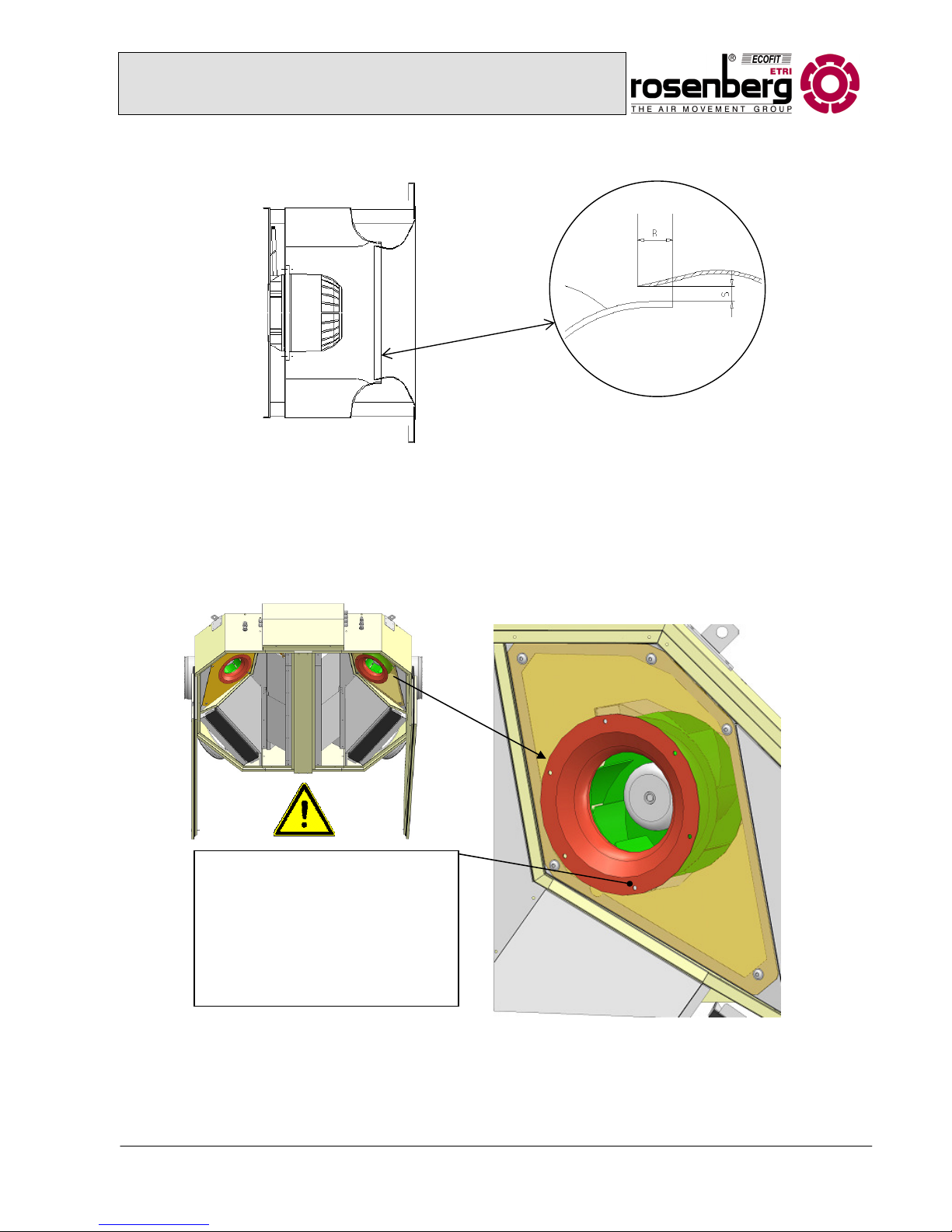
• Remove all 3 transport locks of each fan by unlocking the M6 screws. First remove the inlet
cone plate then adjust the inlet cone.
• Check the gap and the gap cover according to the following drawing:
picture: fan Suprabox D
Operation and Maintenance Manual for Rosenberg
Compact ventilation appliance series SupraBox Comfort
Overhead devices
BA 113 BB 10/12/A/SupraBox
21
• ► Check of the gap and the gap coverage between wheel and inlet cone
• The gap S should be constant on the entire perimeter of the wheel.
• The gap cover R should be about 1 to 2 % of the wheel diameter.
• Adjustment of the cone:
- If the wheel is rubbing at the cone after installation of the unit adjust it as follows:
Abb.: Adjustment of the cone
Picture: gap of the fan
Unlock the six M6 hexagon ratchet
screws with help of the appropriate
tool. Arrange the cone until the wheel
is no longer rubbing and is easy and
free moving. The gap between cone
and wheel should have a constant
size. Lock the ratchet screws.
Operation and Maintenance Manual for Rosenberg
Compact ventilation appliance series SupraBox Comfort
Overhead devices
BA 113 BB 10/12/A/SupraBox
22
7.4.2 Use
Monitor the fans for correct function during operation. Vibrations, pressure
fluctuations or other deviations from the provided operating parameters should be
checked according to the following chapter:
7.4.3 Maintenance and Cleaning
Monitor the unit operation during the first four to twelve weeks regarding the
following points:
- Balance, unusual sounds, vibrations
- Fastening of the fan, the motor and the vibration absorbers
The fan as a fast rotating device needs regular monitoring as well as a three-month maintenance
interval. In case of deviations from the standard operational conditions (air temperature, increased
dust pollution or constant high humidity) or in case of continuous 24-hour operation a shorter interval
must be determined.
Maintenance fan unit Every
3 months
If
necessary
Hygiene
Inspection
Check the fan for dirt, mechanical defects, corrosion and
proper fastening
X X
Check the fan gap X
Clean the fan unit incl. wheel X
Check the wheel for imbalance X
Check the quiet running and the bearing for sounds X
Lubricate or replace the bearing X
Check the fan fastening for tightness and mechanical
damages
X
Check the function of the vibration absorber X
Check for the existence of the fasteners of the protection
units.
X
Check the function of the drainage X X
Check the motor for dirt, mechanical defects, corrosion
and proper fastening
X X
Cleaning of the motor housing X
Check the power supply X
Check the electrical connections for corrosion and proper
fastener
X
Operation and Maintenance Manual for Rosenberg
Compact ventilation appliance series SupraBox Comfort
Overhead devices
BA 113 BB 10/12/A/SupraBox
23
For more thorough cleaning the fans can be removed. Make sure that before removing the fans the
wiring will be disconnected by qualified and trained staff according to the wiring diagram.
Now the allen-head screws of the cone plate can be unlocked and the fan carefully removed.
The water or the cleaning agent respectively should have a neutral ph-value (6 – 8).
7.5 Reverse flow heat exchanger
7.5.1 Startup
Check the correct operation and direction of movement of the bypass flaps of the
reverse flow heat exchanger. Make sure that the bypass flap is closed on startup of
the fans.
Pay attention that the drain pan at the bottom of the reverse flow heat exchanger in
the exhaust air is fixed to the condensate pipe by a trap (at the suction side). The assembly of the trap
is described under point 5.5.
7.5.2 Operation
The automatic bypass flap will be controlled by the central device control using a
final control element.
Operation and Maintenance Manual for Rosenberg
Compact ventilation appliance series SupraBox Comfort
Overhead devices
BA 113 BB 10/12/A/SupraBox
24
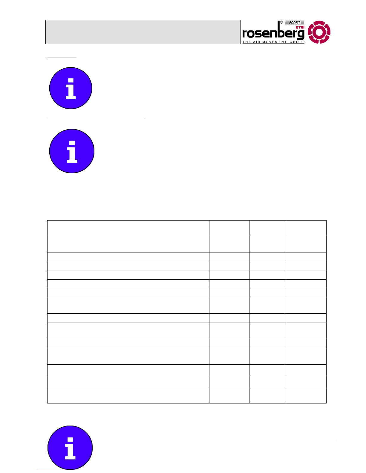
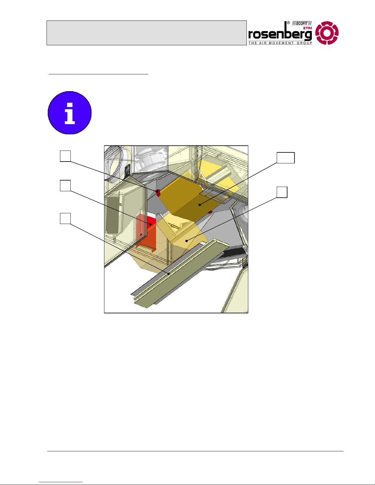
7.5.3 Maintenance and Cleaning
The reverse flow heat exchanger as an installed component needs little
maintenance. For hygienic requirements inspection and maintenance is necessary.
In addition the integrated damper servomotor and fastener need regular checks and
maintenance.
In case of heavy dirt the reverse flow heat exchanger can be removed with the
following steps and safety measures and cleaned under running water.
1 Fixing bracket heat exchanger (6)
Reverse flow exchanger 3 (only
1900D)
2 Clamping heat exchanger
3 Front panel heat exchanger
4 Reverse flow exchanger 1
5 Reverse flow exchanger 2
1
2
3
4/6
5
Picture: Detachment heat exchanger

Operation and Maintenance Manual for Rosenberg
Compact ventilation appliance series SupraBox Comfort
Overhead devices
BA 113 BB 10/12/A/SupraBox
25
In order to ensure safe removal of the heat exchanger, follow the order of the
steps below:
1. Unlock the front panels ([3] pict. detachment heat exchanger) using the 4 allen head screws in
the panel (first remove the plastic plug).
2. Unlock the butterfly screws at the clamp of the heat exchanger ([2] pict. heat exchanger
removal) with simultaneous careful removal of the reverse flow heat exchanger 2 ([5] pict. heat
exchanger removal).
3. Unlock the angle bracket heat exchanger ([1] pict. heat exchanger removal) with simultaneous
careful removal of the reverse flow exchanger 1 ([4] pict. heat exchanger removal), do the
same with heat exchanger 3 ([6] pict. heat exchanger removal)
In order to ensure a safe assembly of the heat exchanger the above listed steps have to be executed
in reverse order.
Maintenance
Every
3 months
If necessary Hygiene Inspection
Check of the hygienic condition X
Check the reverse flow heat exchanger for dirt
X
Cleaning of the plate set with water (water or
steam, the sheet of water should always follow
the disc set from top to bottom)
Clean the module chamber carefully
Completely remove the dirty water
X
Check the condensate and maintenance pan
for dirt
X
Cleaning of the condensate pan X
Check the function of the trap and water level,
fill in water if necessary
X
Check the bypass flap on free movement and
repair it if necessary
X
The water or the used cleaning agent should have a neutral ph-value (6 – 8).
► Warning: The blades of the reverse flow heat exchanger are very sensitive to
contact. Clean and remove with extreme caution!

Operation and Maintenance Manual for Rosenberg
Compact ventilation appliance series SupraBox Comfort
Overhead devices
BA 113 BB 10/12/A/SupraBox
26
7.6 Panel filters
7.6.1 Startup
• Before installation of the filter all seals should be checked for correct fit.
Clean the housing floor.
• Pay attention to the directional arrow for the air stream printed on the panel
filters.
• The filter will be controlled by a differential pressure sensor. If the admissible differential
pressure is exceeded, a signal will appear on the control panel to change the filter. In this
case the filters must be changed immediately. More information can be found in the manual
of the control system.
7.6.2 Operation
The panel filters will be fastened at the assembly frame with a tensioning
angle rail. Draw the angle rail to the body in order to change the filter and
remove it afterwards. Pay attention to the correct fit of the filter at the frame
after the re-assembly. During the filter change check the seal and replace it if
necessary.
7.6.3 Maintenance and Cleaning
The recommended final resistance for this filter version is 150 PA. Always replace
panel filters completely. The filters can be fully incinerated and must be disposed of
accordingly. Clean the housing bottom before installing the new filter.
Change the filter after 12 months of operation or down time at the latest. Note the
filter change with name and date at the unit and in the maintenance book.
Maintenance
Every
3 months
If necessary Hygiene Inspection
Check for dirt by differential pressure control X X X
Check the filter element for damages X
Replacement of the filter insert X
Check the filter for impermeable fit X X X
Check the measure control for the differential
pressure.
X X
Pict. Panel filter overhead
version
 Loading...