

Page 1

ELECTRONIC REVISION
CONTROLLED
Document Number: 9002645 Rev K
Page 2
Rosen Aviation 20‖ SlimLine II Display
Document Number: 9002645
Revision: K
Date: 9/24/09
Template: 4.2-3-6-FM; Revision D; 13 March 2008 Page 2 of 34
Technical Manual, 20” SlimLine II Display
© 2008 by Rosen Aviation, LLC
All Rights Reserved
The information contained herein is proprietary to Rosen Aviation, LLC. No part of this publication
may be reproduced, transmitted, transcribed, stored in a retrieval system, or translated into any
language in any form by any means without written authorization from Rosen Aviation, LLC, except
as allowed under copyright laws.
Disclaimer of Liability
The information contained in this document is subject to change without notice. Because we are
continually improving and adding features to our products, Rosen Aviation, LLC reserves the right
to change specifications without prior notice. Rosen Aviation, LLC shall not be liable for technical or
editorial errors or omissions contained herein.
Rosen Aviation, LLC
1020 Owen Loop South
Eugene, OR 97402
541.342.3802
888.668.4955
Fax: 541.342.4912
www.rosenaviation.com
Page 3

Rosen Aviation 20‖ SlimLine II Display
Document Number: 9002645
Revision: K
Date: 9/24/09
Template: 4.2-3-6-FM; Revision D; 13 March 2008 Page 3 of 34
Contents
1. INTRODUCTION AND DISPLAY OVERVIEW ................................................................. 5
1.1. Unpacking .................................................................................................................. 5
2. INSTALLATION GUIDELINES ......................................................................................... 5
2.1. Monitor Diagrams ...................................................................................................... 6
2.2. Cooling and Ventilation .............................................................................................. 6
2.3. Mounting Options ....................................................................................................... 7
3. VIDEO CONNECTIONS .................................................................................................... 8
3.1. Main Interface Connector, 21W1 Male Combo D ...................................................... 9
3.2. S-Video Connector, 3W3 Male Coax Combo D ....................................................... 10
3.3. DVI Input Connector ................................................................................................ 10
4. TECHNICAL SETUP – TECHNICIAN ON-SCREEN DISPLAY ...................................... 12
4.1. Enabling the On-Screen Display .............................................................................. 12
4.2. Menu Navigation ...................................................................................................... 12
4.3. Main Menu Configuration ......................................................................................... 13
4.3.1. Monitor Info .................................................................................................................. 13
4.3.2. Diagnostic Submenu .................................................................................................... 14
4.3.3. Advanced Menu ........................................................................................................... 16
4.3.4. Clearing Codes ............................................................................................................. 24
4.3.5. Restore Defaults ........................................................................................................... 25
5. OPERATION ................................................................................................................... 25
5.1. Front Switch Panel Features ................................................................................... 25
5.2. On-Screen Display Main Menu ................................................................................ 27
5.3. Picture Submenu ..................................................................................................... 27
5.4. OSD Submenu ......................................................................................................... 28
5.5. Utility Submenu ........................................................................................................ 28
5.6. Auto Submenu ......................................................................................................... 28
5.7. Exit Submenu .......................................................................................................... 28
6. HOT KEYS ...................................................................................................................... 28
7. RS-485 INFORMATION .................................................................................................. 29
7.1. Communication Protocol .......................................................................................... 29
7.2. Packet Format ......................................................................................................... 29
7.3. Packet Timing .......................................................................................................... 29
7.4. Wiring ...................................................................................................................... 30
7.5. Packet Format Description for 2002 Display Commands ........................................ 30
7.6. Network Setup/Ping Address ................................................................................... 31
Page 4

Rosen Aviation 20‖ SlimLine II Display
Document Number: 9002645
Revision: K
Date: 9/24/09
Template: 4.2-3-6-FM; Revision D; 13 March 2008 Page 4 of 34
8. TECHNICAL REFERENCES AND SUPPORT ............................................................... 32
8.1. Technical Support ................................................................................................ .... 32
9. DO-180D QUALIFICATIONS .......................................................................................... 33
9.1. Specifications........................................................................................................... 34
10. REVISION HISTORY .................................................................................................... 34
Page 5
Rosen Aviation 20‖ SlimLine II Display
Document Number: 9002645
Revision: K
Date: 9/24/09
Template: 4.2-3-6-FM; Revision D; 13 March 2008 Page 5 of 34
For help with Outline & Installation drawings, please contact
Rosen Aviation Customer Service at (541) 342-3802.
Touching the LCD with excessive force may leave pressure spots
that show in video display. Handle with care.
1. INTRODUCTION AND DISPLAY OVERVIEW
This manual describes how to install the Rosen 20‖ SlimLine II Display onto your aircraft. It
contains everything you need to know to wire the display and confirm that it is functioning
correctly.
Note: Only trained and qualified personnel should perform installation and service.
1.1. Unpacking
Parts shipped with the 20‖ SlimLine II Display:
Outline & Installation drawing
20‖ SlimLine II Display
Main Interface connector kit (P/N 0300-025)
Optional controllers sold separately:
External 7-button Controller (P/N 0300-408)
Universal Color Remote (P/N 0500-015) shipped with Remote Controller Technical
Information (P/N 100434)
Optional connectors sold separately:
S-Video connector kit (P/N 0300-028)
DVI connector kit (P/N 0300-029)
2. INSTALLATION GUIDELINES
There are several ways to connect the 20‖ SlimLine II Display to an aircraft’s entertainment
system.
Use the pinout descriptions on page 2 of the Outline & Installation drawing to assist in the wiring
process. Pay close attention to the pinout information while completing wiring connections.
Once you access the home page, click on ProductsDisplays20 In SlimLine. Select a
drawing by model number from the drop-down menu in the middle of the page.
Drawings are provided to assist in the installation process. Pay close attention to dimensions and
rotations when considering installation requirements.
Note: This display is for entertainment purposes only; connect to the non-critical power bus.
Page 6
Rosen Aviation 20‖ SlimLine II Display
Document Number: 9002645
Revision: K
Date: 9/24/09
Template: 4.2-3-6-FM; Revision D; 13 March 2008 Page 6 of 34
2.1. Monitor Diagrams
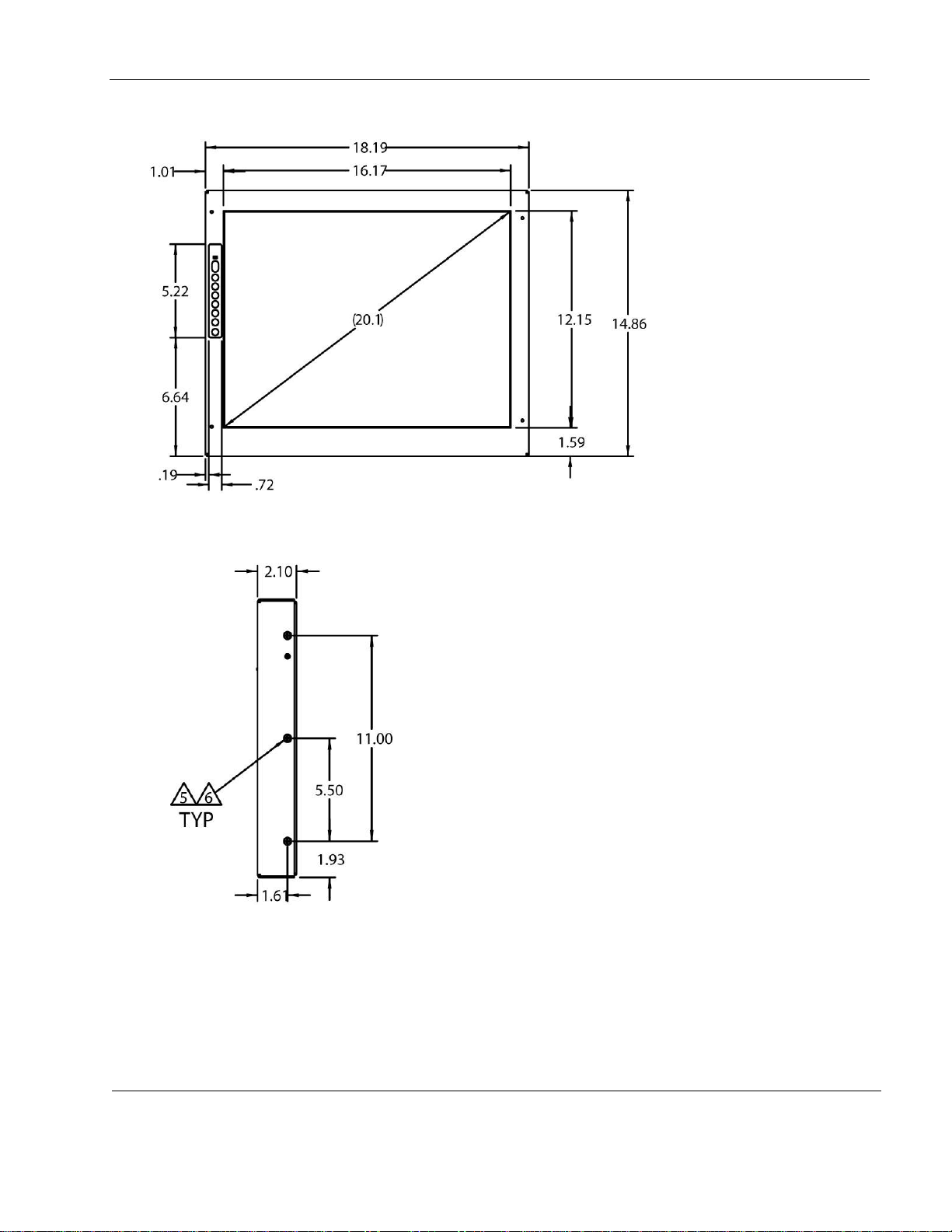
Figure 1 2002 outline dimensions (inches)
Figure 2 Side view dimensions (inches)
2.2. Cooling and Ventilation
The display is cooled by the flow of air, or natural convection. Special care must be taken with
the installation to provide a proper environment for air flow.
Monitor vents: The unit is designed with vent openings on the top, bottom, and rear
surfaces. The entire top vent, and either the entire bottom or entire rear vent must be
Page 7
Rosen Aviation 20‖ SlimLine II Display
Document Number: 9002645
Revision: K
Date: 9/24/09
Template: 4.2-3-6-FM; Revision D; 13 March 2008 Page 7 of 34
1.61
2.34 6.75
13.50
1.19
2.34
13.50
1.61
unobstructed for a minimum of one (1) inch. The vents must also be ducted to free
air.
Ducting: The installation must provide for an inlet duct (at bottom or rear), and an
exhaust duct at the top. Each of these ducts must have a minimum of four (4) square
inches of cross-sectional area.
Note: The display backlight will shut down if internal temperature reaches 140° F. It will not
come back on until the temperature drops 10 degrees below the threshold.
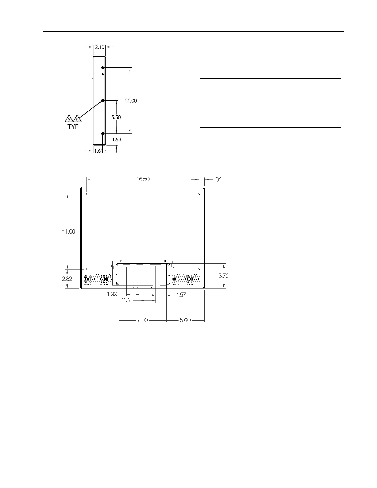
Note: Each mounting hole includes a 10-32 screw. To install the display, remove only the
screws that will be used to install the display. Do not remove the 4-40 flathead screws.
2.3. Mounting Options
Mounting options for this display are as follows:
Mount using all side mounting holes, or
Mount using all top and bottom mounting holes, or
Mount using all rear mounting holes
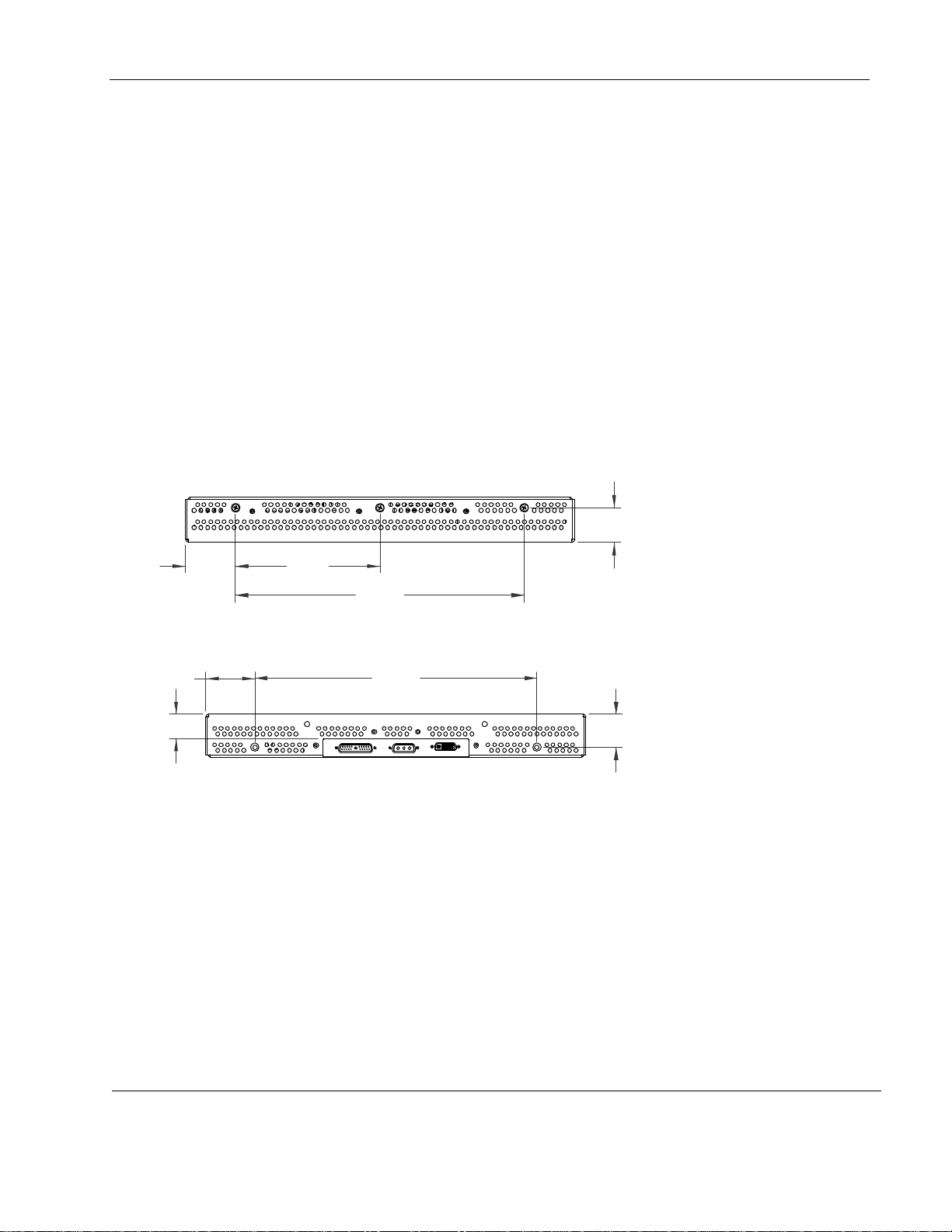
(Dimensions in inches)
Figure 3 Top view with mounting holes
Figure 4 Bottom view with mounting holes
Page 8
Rosen Aviation 20‖ SlimLine II Display
Document Number: 9002645
Revision: K
Date: 9/24/09
Template: 4.2-3-6-FM; Revision D; 13 March 2008 Page 8 of 34
Warning!
!
Maximum screw penetration depth:
Top .75 inches
Bottom .75 inches
Sides .75 inches
Rear .50 inches
Figure 5 Side view with mounting holes
Figure 6 Rear view with mounting holes
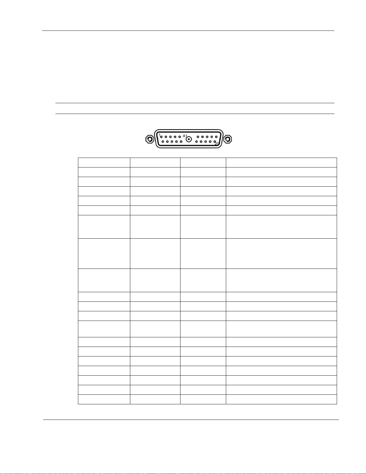
3. VIDEO CONNECTIONS
The three interface connectors for this display are:
21W1 Male Combo D-subminiature with 20 signal inputs for power, control, and IR
inputs, and one (1) shielded coaxial input for composite video
3W3 Male Combo D, Coax for S-Video input
DVI connector for analog RGB and DVI inputs
Page 9
Rosen Aviation 20‖ SlimLine II Display
Document Number: 9002645
Revision: K
Date: 9/24/09
Template: 4.2-3-6-FM; Revision D; 13 March 2008 Page 9 of 34
Pin #
Signal
Input/Output
Description
1
28V return
Input
Aircraft power supply
2
28VDC
Input
Aircraft power supply
3
IR +5V
Output
5V for IR receiver
4
IR signal
Input
Data from IR receiver
5
IR GND
Output
Ground for IR receiver
6
RGB/Video
Select (LVTTL)
Input
Source select switch input internally
pulled up to +3.3V – short to ground to
switch
7
Status output
(LVTTL)
Output
LVTTL level output (+3.3V) indicates
display is on when logic is high –
maximum current. (draw is 10
milliamps ,0V when display is off)
8
Power on/off
(LVTTL)
Input
Power toggle switch – internally pulled
up to +3.3V. Controls the on/off state of
the display.
9
RS-232 GND
N/A
Ground for serial control lines
10
28V RTN
Input
Aircraft power supply
11
28VDC
Input
Aircraft power supply
12
RS-232 RX
Input
Connects to serial switch/cabin
management (9600 baud)
13
RS-232 TX
Output 14
RS-485 (A out)
Output
RS-485 serial A out
15
RS-485 (B out)
Output
RS-485 serial B out
16
RS-485 (A in)
Input
RS-485 serial A in
17
RS-485 (B in)
Input
RS-485 serial B in
18
RS-485 GND
N/A
Ground for RS-485 lines
19
Reserved
Reserved
Reserved
Mating connector kit included with purchase:
Rosen connector kit (P/N 0300-025)
Recommended additional mating connectors (optional)
S-Video connector kit, 3W3 Male Coax Combo D (P/N 0300-028)
DVI connector kit for analog RGB and DVI inputs (P/N 0300-029)
Note: The main connector backshell is chassis ground.
Warning! Do not plug or unplug display while power is applied!
3.1. Main Interface Connector, 21W1 Male Combo D
Page 10
Rosen Aviation 20‖ SlimLine II Display
Document Number: 9002645
Revision: K
Date: 9/24/09
Template: 4.2-3-6-FM; Revision D; 13 March 2008 Page 10 of 34
Pin #
Signal
Input/Output
Description
20
Reserved
Reserved
Reserved
A1-signal
Composite
video
Input
Composite video input, 1 Vpp, 75 ohm
A1-shield
Composite
video return
Input
Shield for composite video
Shell
Chassis ground
Pin #
Signal
Input/Output
Description
A1 Signal
S-Video
luminance
Input
S-Video luminance signal
A1 Shield
S-Video
luminance shield
Input
S-Video return
A2 Signal
S-Video
chrominance
Input
S-Video chrominance signal
A2 Shield
S-Video
chrominance
shield
Input
S-Video return
A3 Signal
Reserved
Reserved
Reserved
A3 Shield
Reserved
Reserved
Reserved
Pin #
Signal
Input/Output
Description
1
T.M.D.S. Data2-
Input
Digital video serial channel 2 data
2
T.M.D.S. Data2+
Input
Digital video serial channel 2 data
3
T.M.D.S. Data2/4
shield
Input
Digital video serial channel 2 and 4
shield
4
T.M.D.S. Data4-
Input
Digital video serial channel 4 data
5
T.M.D.S. Data4+
Input
Digital video serial channel 4 data
6
DDC clock
Input
Display data channel clock signal
6
1
7
17
C1
C2
C3
C4
16
24
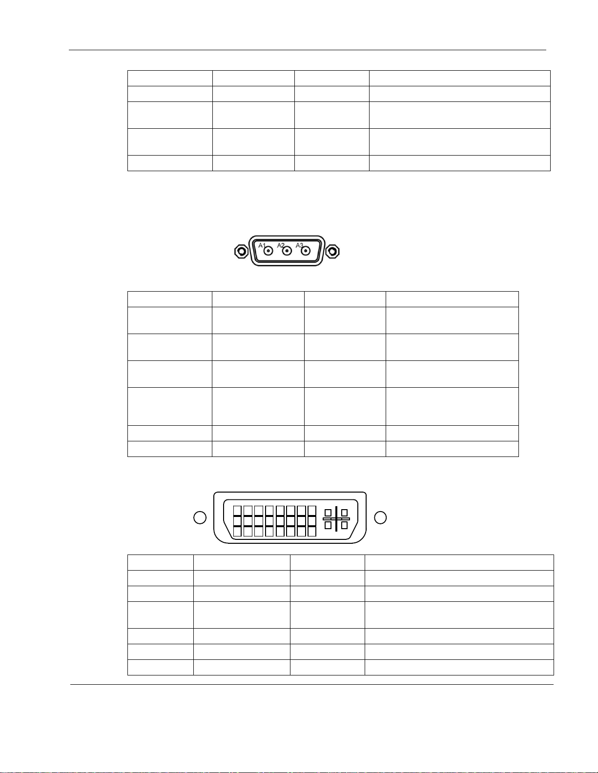
3.2. S-Video Connector, 3W3 Male Coax Combo D
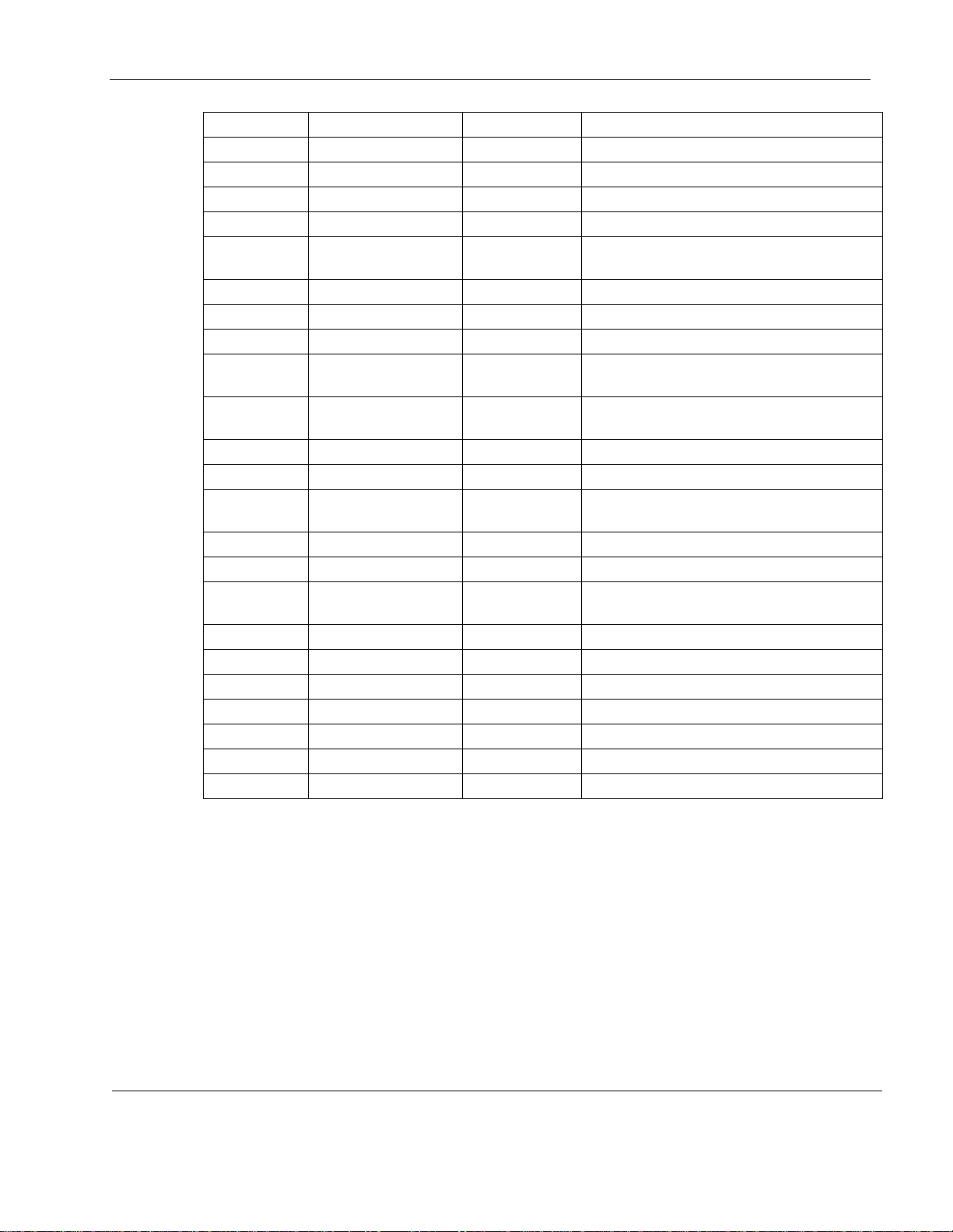
3.3. DVI Input Connector
Page 11
Rosen Aviation 20‖ SlimLine II Display
Document Number: 9002645
Revision: K
Date: 9/24/09
Template: 4.2-3-6-FM; Revision D; 13 March 2008 Page 11 of 34
Pin #
Signal
Input/Output
Description
7
DDC data
Output
Display data channel data signal
8
Analog VSync
Input
Analog RGB VSync input 0-5V
9
T.M.D.S. data1-
Input
Digital video serial channel 1 data
10
T.M.D.S. data1+
Input
Digital video serial channel 1 data
11
T.M.D.S. data1/3
shield
Input
Digital video serial channel 1 and 3
shield
12
T.M.D.S. data3-
Input
Digital video serial channel 3 data
13
T.M.D.S. data3+
Input
Digital video serial channel 3 data
14
5V power
Input
5V power for display data circuit
15
GND for 5V,
HSync, VSync
Input
Ground for analog sync signals and 5V
power
16
Hot plug detect
Output
Indicates to source that display is
connected
17
T.M.D.S. data0-
Input
Digital video serial channel 0 data
18
T.M.D.S. data0+
Input
Digital video serial channel 0 data
19
T.M.D.S. data0/5
shield
Input
Digital video serial channel 0 and 5
shield
20
T.M.D.S. data5 -
Input
Digital video serial channel 5 data
21
T.M.D.S. data5+
Input
Digital video serial channel 5 data
22
T.M.D.S. clock
shield
Input
Shield for digital video serial clock signal
23
T.M.D.S. clock+
Input
Digital video serial channel clock signal
24
T.M.D.S. clock-
Input
Digital video serial channel clock signal
C1
Analog red
Input
Analog RGB red input, 0.7V, 75 ohm
C2
Analog green
Input
Analog RGB green input, 0.7V, 75 ohm
C3
Analog blue
Input
Analog RGB blue input, 0.7V, 75 ohm
C4
Analog HSync
Input
Analog RGB HSync input, 0-5V
C5
Analog Ground
Input
Analog RGB ground
Page 12
Rosen Aviation 20‖ SlimLine II Display
Document Number: 9002645
Revision: K
Date: 9/24/09
Template: 4.2-3-6-FM; Revision D; 13 March 2008 Page 12 of 34
On-screen display will not function if the special filter is enabled.
To disable special filter, go to Section 5.5 Utility Submenu
4. TECHNICAL SETUP – TECHNICIAN ON-SCREEN DISPLAY
The display receives Composite, Analog RGB, S-Video, and Digital Video Input (DVI). DVI input
is shown as Digital RGB in the on-screen display when switching between video sources.
4.1. Enabling the On-Screen Display
To access the on-screen display (OSD) configuration for advanced settings, use the front-panel
keys or an IR remote to access the Technician Menu. On the front panel, press the following
button sequence:
◄, ►, ▲, ▼, ◄, ►, ▲, ▼, ▲, ▲, ▲, and then press Menu.
This sequence prevents passengers from accidentally accessing the configuration on-screen
display mode.
4.2. Menu Navigation
Use the front-panel keys or an IR remote to move through menu selections. The current menu
screen title is always shown at the top of the screen.
Use up and down (▲▼) arrow keys to move the menu cursor to a different menu option
line.
Press the Menu key to select a menu option, or to accept an adjusted or changed menu
option.
Use left and right arrow keys (◄ ►) to adjust or change menu options.
Menu selections that have a submenu option have >> shown at the right side of the
menu option line.
Menu selections that return you to the previous menu have << shown at the right side of
the menu option line.
When > is shown at the left side of a menu option line, the cursor is on that line. This
does not mean that the menu option line is currently selected. A menu option line is
selected by pressing the Menu key.
Note: Most menus have help text at the bottom of the screen indicating which keys navigate
that menu.
Page 13
Rosen Aviation 20‖ SlimLine II Display
Document Number: 9002645
Revision: K
Date: 9/24/09
Template: 4.2-3-6-FM; Revision D; 13 March 2008 Page 13 of 34
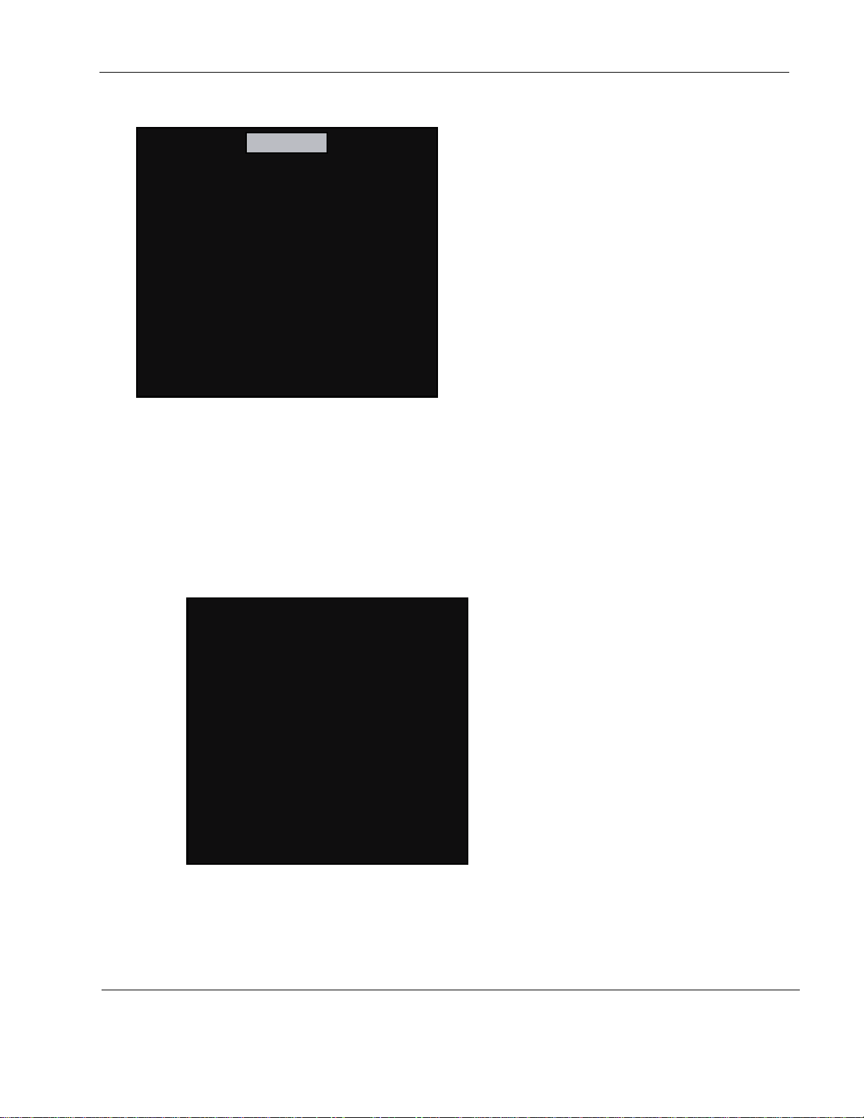
Main Menu
> Monitor Info >>
Diagnostics >>
Advanced Settings >>
Restore Defaults >>
Exit OSD >>
[UP] [DOWN] move cursor
[MENU] select option
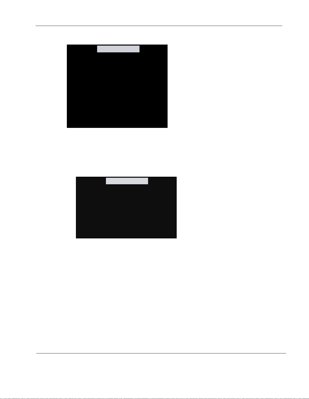
firmware rev: rev A
CSOC rev: rev A
Total hrs: 115:53
Backlight hrs: 93
Composite: 82
ARGB: 3
S-video: 0
DVI: 8
Power Cycles: 145
Glitch Count: 4
Temp: 77F
< press any key to exit >
4.3. Main Menu Configuration
Figure 7 Main Menu options
The Main Menu has a time-out setting that automatically returns the monitor to normal
operation if no keys are pressed for one (1) minute. The submenus do not have this time-out
setting.
To manually exit the Main Menu, move the cursor to the Exit OSD menu line and then press
the Menu key.
4.3.1. Monitor Info
Select the Monitor Info submenu to view information on the current status of the display.
The example below shows the Monitor Info submenu selection:
Figure 8 Monitor Info submenu
Page 14
Rosen Aviation 20‖ SlimLine II Display
Document Number: 9002645
Revision: K
Date: 9/24/09
Template: 4.2-3-6-FM; Revision D; 13 March 2008 Page 14 of 34
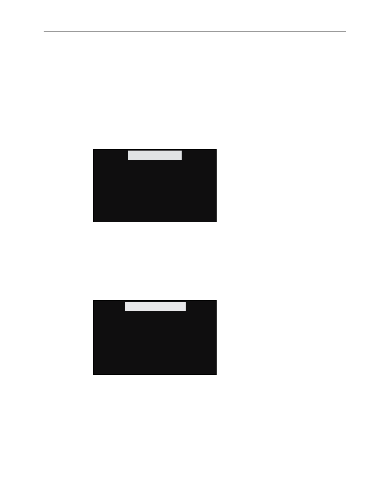
Diagnostic Menu
Self-test >>
Measure Comp Video
> Measure S-video
Measure RGB Red
Measure RGB Green
Measure RGB Blue
Input Scan >>
Main Menu <<
[UP] [DOWN] move cursor
[Menu] select option
eeprom access ok
RTC ram ok
RTC battery ok
temp sensor ok
< press any key to exit >
Self Test Result
4.3.2. Diagnostic Submenu
Figure 9 Diagnostic submenu option
4.3.2.1. Self-test
Select the Self-test menu to initiate a test that determines and then displays the
status for some of the monitor’s internal components. This test runs automatically
when power is applied to the monitor, but it can be run manually from this menu
selection. A sample Self-test result is shown below.
Figure 10 Self-test submenu example
Page 15
Rosen Aviation 20‖ SlimLine II Display
Document Number: 9002645
Revision: K
Date: 9/24/09
Template: 4.2-3-6-FM; Revision D; 13 March 2008 Page 15 of 34
RGB Green Level
Max 2.1
Avg 1.1
Min .2
< press any key to exit >
Scanning For Inputs
Composite Input found
S-Video not found
ARGB not found
DVI found
< press any key to exit >
4.3.2.2. Video Level Test
There are five tests for video signal levels:
Measure Composite Video
Measure S-Video
Measure RGB Red
Measure RGB Green
Measure RGB Blue
Each video level test measures the average voltage level of a particular video input
signal. Select the desired video signal to initiate a test. See below for a Video Level
Test result example.
Figure 11 Video Level Test result example
4.3.2.3. Input Scan
Select the input scan menu to initiate a short test that determines if the monitor can
detect any valid video input signals. The status of each input signal displays when
the test completes.
Note: Input scan tests are based on detecting the sync signals from each signal.
It is possible for a video signal to be physically connected to the monitor but still fail
this scan test if the voltage level is too high or too low.
Figure 12 Input Scan result example
Page 16

Rosen Aviation 20‖ SlimLine II Display
Document Number: 9002645
Revision: K
Date: 9/24/09
Template: 4.2-3-6-FM; Revision D; 13 March 2008 Page 16 of 34
Advanced Menu
> Start-up Settings >>
Clock Settings >>
Source Setup >>
Session Records >>
Network Settings >>
IR Settings >>
Main Menu <<
[UP] [DOWN] move cursor
[MENU] select option
Start-up Mode
Start-up Mode: auto-on
Glitch-time: 1.2
Splash Screen: "Rosen"
Membrane SW: enabled
> Load Default Settings
Exit -- save changes
Exit -- discard changes
[UP] [DOWN] move cursor
[MENU] select option
4.3.3. Advanced Menu
The Advanced Menu is extensive. Use the following pages for guidance when
selecting Advanced Menu options and submenus.
Figure 13 Advanced Settings submenu options
4.3.3.1. Start-up Settings
Figure 14 Start-up Mode settings example
Start-up Mode
There are four settings available for the Start-up Mode:
Auto-on: The monitor always starts up in the ON state when 28V is applied. The
default mode is Auto-on.
Auto-off: The monitor always starts up in the STANDBY state when 28V is
applied.
Restore Last: The monitor returns to the previous power and video settings
after any power interruption.
Constant SW Mode: See ―Start-up Mode below.
Start-up Mode - Power On/Off Input Signal
The Power On/Off Input Signal pin (pin 8) can be used to control the Monitor’s On/Off
state. When Start-up Mode is set to Auto-on, Auto-off or Restore Defaults, the On/Off
Page 17

Rosen Aviation 20‖ SlimLine II Display
Document Number: 9002645
Revision: K
Date: 9/24/09
Template: 4.2-3-6-FM; Revision D; 13 March 2008 Page 17 of 34
signal is activated by a momentary ground input. The monitor will toggle the On/Off
state in response to this momentary ground signal. When the Start-up Mode is set to
Constant SW, the power state is controlled directly by the voltage level on the pin. Zero
volts will turn the monitor Off, and 3V will turn it On. Note that when in Constant SW
Mode, the membrane switch, external controller and IR remote power buttons have no
effect.
Glitch-time
Glitch-time settings help control the monitor state when power is first applied in Auto-on
or Auto-off modes. For example, during a normal power-up sequence, when 28V power
has been off for several hours, the initial state of the monitor is set by the Start-up mode
selection. If 28V power is briefly interrupted while the monitor is on, the monitor will
respond by restoring the previous state and ignoring the Start-up mode setting. (One
example of a brief power interruption is when an aircraft switches from auxiliary power
unit (APU) to engine power.)
Note: The Glitch-time setting controls the length of time that the monitor uses to choose
between a normal power-up sequence and a power interruption sequence. The range
of this setting is from .5 seconds to 25.5 seconds, in increments of .1 seconds. The
default value is 1 second. The Glitch-time setting has no effect in ―Restore Last‖
Start-up mode.
Splash Screen
There are two splash screens available on this monitor; one is a solid blue background,
and the other is a white background with the Rosen Aviation Displays logo. The splash
screen appears for approximately 8 seconds when 28V power is first applied to the unit.
Use the Splash Screen menu option to choose the splash screen desired.
Front Panel Keys (Membrane SW)
The Front Panel Keys can be disabled for situations where the monitor is installed in a
bulkhead. If the possibility exists of the keys being inadvertently held in by the mounting
bezel in front of the monitor, select ―disabled‖ for this setting.
Note: Disabling Front Panel Keys only takes effect after the on-screen Main Menu
display is exited. While the on-screen display is active, the keys will still operate. Once
the keys become inoperable, you may still enter the technician sequence to access the
technical setup OSD.
Page 18
Rosen Aviation 20‖ SlimLine II Display
Document Number: 9002645
Revision: K
Date: 9/24/09
Template: 4.2-3-6-FM; Revision D; 13 March 2008 Page 18 of 34
Clock Menu
Year: 2004
Month: 06
Day: 03
Hour: 16
Minute: 00
> Exit -- save changes
Exit -- discard changes
________________________
[LEFT] [RIGHT] adjust
[UP] [DOWN] move cursor
[MENU] select option
Load Default Settings
Use this menu option to restore start-up settings to the factory configuration. This option
does not change other monitor settings. The factory start-up configuration is as follows:
Start-up mode = auto-on
Glitch-time = 1.0 seconds
Splash screen = Rosen Aviation Displays
Front Panel Keys = enabled
4.3.3.2. Clock Settings
This monitor contains a battery-backed real-time clock. The clock is set during
monitor production and should not need adjustment during the monitor’s life. If the
clock setting needs adjustment for any reason, access the Clock Menu to make
adjustments.
Figure 15 Clock settings example
Page 19
Rosen Aviation 20‖ SlimLine II Display
Document Number: 9002645
Revision: K
Date: 9/24/09
Template: 4.2-3-6-FM; Revision D; 13 March 2008 Page 19 of 34
Source Mode Set-up
[] Auto-Detect Mode >>
[] Constant SW Mode >>
[] Momentary SW Mode >>
> [I] Manual Mode
Advanced Menu <<
[UP] [DOWN] move cursor
[MENU] select option
[I] indicates current mode
4.3.3.3. Source Setup
Use the Source Setup menu selections to determine how the monitor selects video
sources. There are four modes available for selecting video sources:
Auto-Detect Mode
Constant Switch Mode
Momentary Switch Mode
Manual Mode
Figure 16 Source Mode Set-up menu
A line is shown between the brackets of the currently selected mode. Note that the
Manual Mode option has no other settings options, while the other three modes have
separate setup menus.
4.3.3.3.1. Auto-Detect Mode
Auto-Detect mode automatically switches the Video Source based on a priority
level assigned to each source. The priority levels are assigned, with level 1 being
the highest priority level and level 4 being the lowest level. The monitor always
displays the highest priority input that is available.
Note: To have a valid configuration, there must be unique sources assigned to
priority levels 1 and 2; levels 3 and 4 are optional.
For example, a typical configuration would be to have composite video as priority
2, and analog RGB as priority. This would cause the monitor to automatically
switch to the analog RGB input whenever a user attached a laptop computer to
the analog RGB input.
Page 20
Rosen Aviation 20‖ SlimLine II Display
Document Number: 9002645
Revision: K
Date: 9/24/09
Template: 4.2-3-6-FM; Revision D; 13 March 2008 Page 20 of 34
Auto-Detect Setup
Priority 1: ARGB
Priority 2: COMPOSITE
Priority 3: -
Priority 4: -
> Exit -- save changes
Exit -- discard changes
_____________________
[UP] [DOWN] move cursor
[RIGHT] adjust
[MENU] select option
Constant Mode Setup
> Switch Low: ARGB
Switch Hi: COMPOSITE
Exit -- save changes
Exit -- discard changes
_____________________
[UP] [DOWN] move cursor
[RIGHT] adjust
[MENU] select option
Note: The menu will not allow an invalid configuration to be saved. If an invalid
setup is listed in the menu, the ―save‖ option is automatically replaced by an
―Invalid Setup!‖ warning.
Figure 17 Auto-Detect Mode submenu example
4.3.3.3.2. Constant Switch Mode
Constant Switch mode selects one of two video sources based on the state of a
single pole switch connected between ground and the select switch input pin (pin
6 on the 21W1 main interface connector). You can select any of the available
sources for the two switch conditions.
When the select switch pin is connected to ground, the monitor switches to the
video source indicated in the ―Switch Closed‖ menu setting. When the select
switch pin is open (not connected to ground), the monitor selects the video source
indicated in the ―Switch Open‖ menu setting.
Note: The two sources selected must be different to be considered a valid
configuration. The menu will not allow you to save an invalid configuration.
Figure 18 Constant Switch Mode submenu example
Page 21
Rosen Aviation 20‖ SlimLine II Display
Document Number: 9002645
Revision: K
Date: 9/24/09
Template: 4.2-3-6-FM; Revision D; 13 March 2008 Page 21 of 34
Momentary SW Setup
> Source 1: ARGB
Source 2: COMPOSITE
Source 3: DVI
Source 4: -
Exit -- save changes
Exit -- discard changes
_____________________
[UP] [DOWN] move cursor
[RIGHT] adjust
[MENU] select option
4.3.3.3.3. Momentary Switch Mode
Use the Momentary Switch mode to select video modes in a predefined sequence
each time the source key is pressed, or each time an external momentary switch
connected to the select switch input is pressed.
The sequence list can contain two or more video sources, but there can be no
duplicated entries. There are no restrictions on where each video source can
appear in the sequence. The monitor defaults to the first source in the list upon
start-up. The menu will not allow you to save an invalid configuration.
4.3.3.3.4. Manual Mode
4.3.3.4. Session Records
Use Session Records to access past configuration information. As a diagnostic tool,
this monitor stores a brief record of the last 25 times that the monitor was turned on.
The information contained in each record is as follows:
Figure 19 Momentary Switch Mode submenu example
Use Manual Mode to change the input source by pressing the front panel source
key. There is no auto-detection or skipping of modes in this configuration. The
monitor will power up in the same video mode that it was in prior to being shut
down.
The starting time and date
Video modes used
The maximum internal temperature
The minimum internal temperature.
The source selection mode
The power-up mode used
The self-test flag results (00 = normal)
The ending time and date
Page 22
Rosen Aviation 20‖ SlimLine II Display
Document Number: 9002645
Revision: K
Date: 9/24/09
Template: 4.2-3-6-FM; Revision D; 13 March 2008 Page 22 of 34
Index 1
Start: Dec 15 04 08:53
Video modes:
DVI, S-Video
Max temp: 96
Min temp: 75
Constant mode
Start up: normal start
Self test flag: 00
Stop: Dec 15 04 11:24
_____________________
[MENU] to exit
[DOWN] show next record
Figure 20 Session Records menu example
4.3.3.5. Network Settings
Use Network Settings if you are using RS-485. The Search Network setting looks for
other attached Rosen products. It lists either the products or states ―No other devices
found.‖ See Section 7 RS-485 Information on page 29 for more information about
controlling.
4.3.3.6. IR (Remote Control) Settings
This monitor uses standard Rosen remote control codes, and it also has the ability to
learn new codes from a different remote. The new remote must have an ―NEC- style‖
32-bit IR output.
Note: Learning new codes for a function will not erase the standard codes. The
default Rosen IR codes will always work, regardless of any learned codes.
Page 23
Rosen Aviation 20‖ SlimLine II Display
Document Number: 9002645
Revision: K
Date: 9/24/09
Template: 4.2-3-6-FM; Revision D; 13 March 2008 Page 23 of 34
IR Settings Menu
[Power Button]
Current Code: none
Next code
> Learn new code >>
Clear this code
Clear ALL codes
Advanced menu <<
_____________________
[UP] [DOWN] move cursor
[Menu] select option
IR Learn [IR Power]
> Exit -- discard changes
1st code: -
2nd code: -
3rd code: -
Press new button 3 times,
pausing between each press.
If all 3 codes match, the code
is valid
4.3.3.6.1. Programming a New IR Code:
The following information details an example of programming a new IR code. In
this example, a new IR code will be added for the Power key.
Figure 21 IR Settings Submenu Option
Access the IR Settings Menu by Navigating from the Main Menu to Advanced Settings to
IR Settings Menu.
Move the cursor to the Next Code selection, use the arrow keys to set the cursor on the
first line of the menu, and then find and press the remote control Power button.
Move the cursor down to the Next Code option line and then press the Menu key.
Move the cursor down to the Learn New Code option line and then press the Menu key;
this activates the IR learning menu as shown below.
Figure 22 IR Settings Submenu Option
Once the IR Learn menu is activated, press the remote control button that you want to
program as the new Power Button three (3) times, pausing slightly between each
press.
A code should appear each time you press the remote control button. If the codes
are identical, which they should be, the submenu will change as shown below.
Page 24
Rosen Aviation 20‖ SlimLine II Display
Document Number: 9002645
Revision: K
Date: 9/24/09
Template: 4.2-3-6-FM; Revision D; 13 March 2008 Page 24 of 34
IR Learn [IR Power]
Exit -- save new code
> Exit -- discard changes
1st code: - 807FDC2F
2nd code: - 807FDC2F
3rd code: - 807FDC2F
Press new button 3 times,
pausing between each press.
If all 3 codes match, the code
is valid
Figure 23 IR Learn (IR Power menu and options)
Note: If the codes do not match, or do not change when you press the remote
control button, make sure that the remote is pointed directly at the IR sensor. If
codes still do not match or do not update when you press the remote control button,
your remote control may not be compatible with this monitor. Try using a different
remote control.
If you press a remote control button that is already stored in the monitor while in
Learn mode, it will be ignored.
Move the cursor to the Exit – Save New Code option line and press the Menu key to add
the change to the remote control database for this monitor. The new remote control
button will work (however, the original remote code will also still work).
When a new IR code is saved, the IR Settings Menu returns to the display, and the
new code is shown on the Current Code line. To store more codes from a remote,
repeat the operation described above for each function desired. The list of available
buttons and functions appears below:
IR remote functions and buttons list
Power button
Menu button
Source button
Up button
Down button
Left button
Right button
OSD on
Select Composite Video
Select S-Video
Select Analog RGB
Select DVI
4.3.4. Clearing Codes
To clear one stored code, use the Next Code option to select the function to be cleared.
Move the cursor to the Clear This Code option and press the menu key. The current
code line will now read ―none‖ for this function. To clear all stored codes at once, move
the cursor to the Clear All Codes option and press the Menu key. The current code line
will now read ―none‖ for all stored codes.
Note: To return to the Advanced Menu, move the cursor to the Advanced Menu option
and press the menu button.
Page 25
Rosen Aviation 20‖ SlimLine II Display
Document Number: 9002645
Revision: K
Date: 9/24/09
Template: 4.2-3-6-FM; Revision D; 13 March 2008 Page 25 of 34
Defaults Menu
> Restore Factory Setup
Main Menu <<
___________________
[UP] [DOWN] move cursor
[MENU] select option
4.3.5. Restore Defaults
The Restore Defaults Submenu restores factory default settings for the monitor. It does
not erase maintenance data or change the internal time and date.
Figure 24 Restore Defaults Submenu Option
The following conditions will be set by selecting this option:
The front panel membrane switch will be enabled
The network settings will be cleared
The start-up splash screen will be set to show the Rosen Aviation Displays
logo screen
The power glitch time setting will be set to 1 second
All stored IR codes will be cleared
The start-up mode will be set to auto-on, auto-detect RGB
5. OPERATION
5.1. Front Switch Panel Features
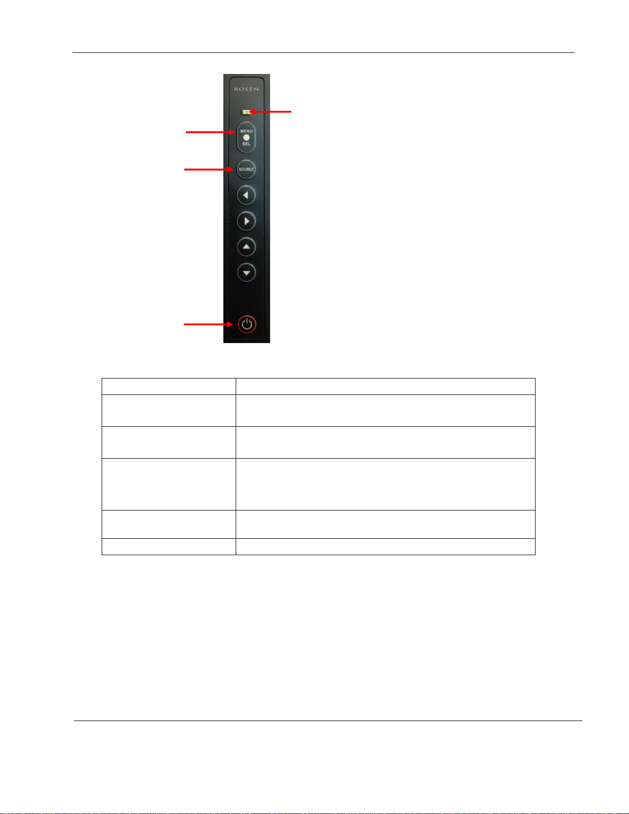
To operate the 20‖ SlimLine II display, use the front switch panel buttons shown below.
(External controller or IR remote control options are available separately.)
Page 26
Rosen Aviation 20‖ SlimLine II Display
Document Number: 9002645
Revision: K
Date: 9/24/09
Template: 4.2-3-6-FM; Revision D; 13 March 2008 Page 26 of 34
Feature
How it Works
Power Status LED
When the LED is green, display is on. When the LED is red,
display is in Standby Mode.
Menu/Sel
Press to view the OSD Main Menu and to select the highlighted
Main Menu option.
Source
Press to toggle the video source between Analog RGB, Digital
RGB, S-Video, and Composite video. Note: This only functions
when the Advanced Menu’s Source Setup is set to Momentary
Ground or Manual Mode.
▼▲►◄
Press to select a menu option or to increase or decrease a
value.
Power
Press to power the display on or off.
Menu Select
Source
Power
Power
Status LED
Figure 25 Front Switch panel
Front Switch Panel Features
Page 27
Rosen Aviation 20‖ SlimLine II Display
Document Number: 9002645
Revision: K
Date: 9/24/09
Template: 4.2-3-6-FM; Revision D; 13 March 2008 Page 27 of 34
Menu Option
How it Works
Brightness
Adjusts picture brightness
Contrast
Adjusts picture contrast
Hue
Shifts the color balance or tint
Saturation
Intensifies the image colors
Filter Select
Increases the clarity of the picture
Phase
Removes noise in analog RGB
Frequency
Adjusts the picture size in RGB mode
H Position
Adjusts horizontal position adjustment
V Position
Adjusts vertical position
Sharpness
Adjusts picture sharpness
Return
Returns OSD to the Main Menu
These options are
not available in
digital RGB
(DVI/1080p) mode
These options
available only in
Composite mode
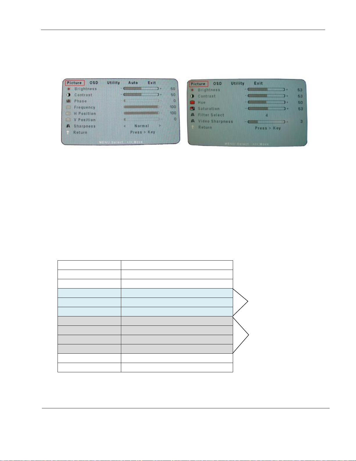
5.2. On-Screen Display Main Menu
The On-Screen Display (OSD) provides a set of menus that enable you to adjust or view the
display’s features. Main Menu selections lead to submenus with additional choices. Press the
Menu Select button on the switch panel to open the Main Menu.
Figure 26 Main Menu for analog and digital RGB modes (left) and for composite mode (right)
To switch to different Main Menus (OSD, Utility, and Auto), press the ◄ ► buttons on the front
switch panel.
To highlight a submenu, press the ▼ button on the switch panel. When submenus are
highlighted, press the ◄ ► buttons to adjust up or down.
To return to the Main Menu, press the ► button on the switch panel to highlight Return in the
submenu.
To exit Main Menu, press ► button until Exit is highlighted and then press the Menu Select
button.
Note: It takes ten seconds for changes to be stored into memory.
5.3. Picture Submenu
Note: Phase, Frequency, H Position and V Position appear only in analog RGB mode. If you
change frequency in RGB mode, the H Position, V Position and Phase are automatically reset
to default.
Page 28
Rosen Aviation 20‖ SlimLine II Display
Document Number: 9002645
Revision: K
Date: 9/24/09
Template: 4.2-3-6-FM; Revision D; 13 March 2008 Page 28 of 34
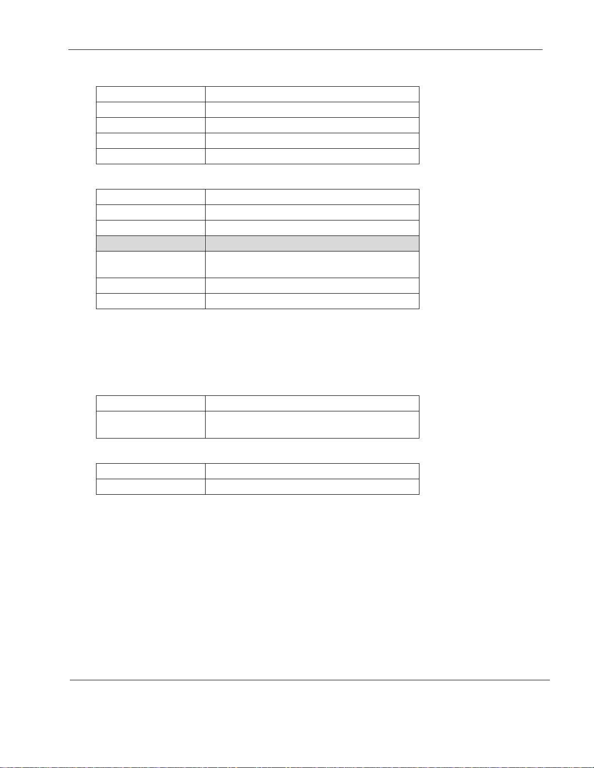
Menu Option
How it Works
H Position
Adjusts OSD horizontal position
V Position
Adjusts OSD vertical position
OSD Timeout
Adjusts time in which OSD turns off if left alone
Return
Returns OSD to the Main Menu
Menu Option
How it Works
Freeze Frame
Freezes picture frame
Reset
Returns options to default settings
Special Filter
Slow/fast motion picture filter
Color Temperature
Opens Color Adjustment submenu, where you
can adjust red, green, and blue values
Information
Provides monitor info
Return
Returns OSD to the Main Menu
Menu Option
How it Works
Auto
Automatically adjusts image size in analog and
digital RGB modes
Menu Option
How it Works
Exit
Closes the screen. To exit menu, press ◄.
5.4. OSD Submenu
5.5. Utility Submenu
Note: Tech menu will not function when special filter is enabled and the digital RGB mode
(DVI/1080p) will not display correctly with special filter enabled. Special filter can only be enabled
in composite mode.
5.6. Auto Submenu
5.7. Exit Submenu
6. HOT KEYS
Hot keys are a quick way of adjusting brightness, contrast, picture-in-picture (PIP), and the
scaling modes. To activate the hot keys, press the ▲▼ buttons on the front switch panel to cycle
through these modes, and then use the ►◄ buttons to change values. The hot keys will not
work if an OSD menu is open.
Page 29
Rosen Aviation 20‖ SlimLine II Display
Document Number: 9002645
Revision: K
Date: 9/24/09
Template: 4.2-3-6-FM; Revision D; 13 March 2008 Page 29 of 34
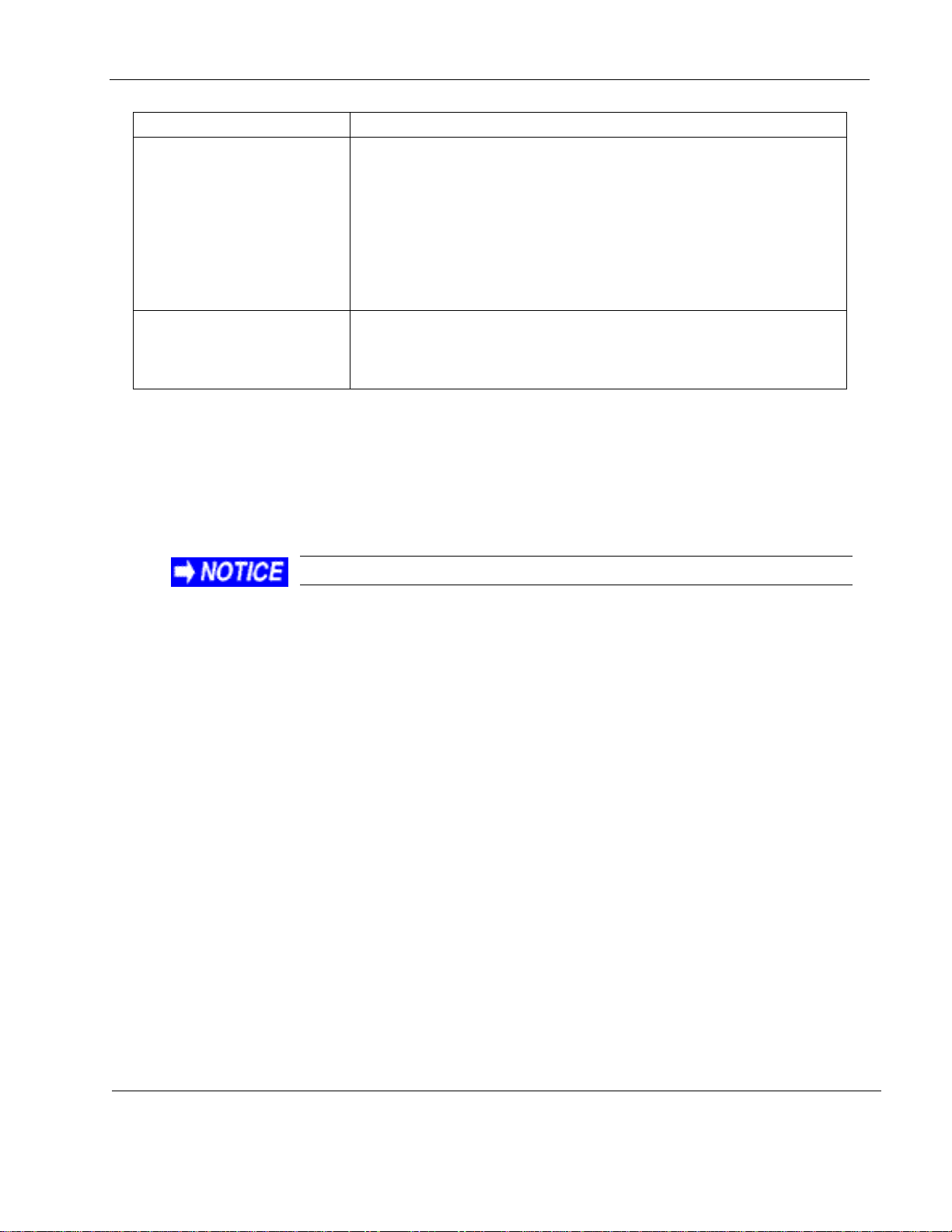
Hot Key Option
How it Works
Scaling mode
The scaling mode will adjust the picture depending on the type of
formatted DVD disc you are using. Note: If picture looks stretched,
adjust the scaling mode.
Fill All
Fill Aspect Ratio
One To One
Letterbox 16:9 fill (tall) [Composite Only]
Anamorphic [Composite Only]
Picture-in-Picture (PIP)
[RBG/DVI only]
The small screen in the upper left-hand corner will display composite
video in small, medium, and large PIP when in RGB/DVI modes.
Note: PIP will only function correctly with progressive video signals. It
will not function with interlacing video signals (480i/1080i).
The Rosen 2002 is set to address 1 by default.
7. RS-485 INFORMATION
This section defines the type, formats and timing of serial message packets that can be used to
control the 2002 display through a daisy-chained RS-485 serial connection. All RS-485-enabled
Rosen Aviation displays and other Rosen Aviation equipment will fully implement the applicable
messages in this document. A maximum of 31 devices may be connected on a half-duplex
network. Each device should be assigned a unique address from 1 to 31.
Please note that Rosen Aviation equipment is not specifically designed to operate as part of a
network with other manufacturers’ equipment unless the other equipment meets the
requirements defined in this document.
7.1. Communication Protocol
9600 Baud
8 data bits
1 stop bit
no parity
7.2. Packet Format
There are typically 3 bytes per message. The first byte is a header byte and the second
identifies the specific command. The third byte is the network address. A network address byte
of 0 is reserved as the ―global‖ address, in other words all slave units should respond to that
command.
7.3. Packet Timing
Within a message packet, there is a maximum time of 20mSec between bytes.
Messages with bytes sent more than 20mSec apart will not be recognized by the
receiving unit.
There should be a minimum elapsed time of 50mSec between any 2-message packets.
This allows the given processor sufficient time to process the previous message.
Page 30
Rosen Aviation 20‖ SlimLine II Display
Document Number: 9002645
Revision: K
Date: 9/24/09
Template: 4.2-3-6-FM; Revision D; 13 March 2008 Page 30 of 34
Messages sent less than 50mSec apart are not guaranteed to be processed by the
receiving unit.
7.4. Wiring
Rosen Aviation equipment uses a half-duplex wiring layout. Only two RS-485 wires need to be
run between each individual unit. On the 20‖ SL II monitor, the two sets of RS-485 A and B
wires must be externally connected together. For proper operation, connect pin 14 to pin 16
and connect pin 15 to pin 17 on the 21W1 connector.
7.5. Packet Format Description for 2002 Display Commands
Power
Power On
Byte 1: 0x81 Power Message Header
Byte 2: 0x0f Power on command
Byte 3: network id
0x00 reserved for global id (all power slave units respond)
Power Off
Byte 1: 0x81 Power Message Header
Byte 2: 0xf0 Power off command
Byte 3: network id
0x00 reserved for global id (all power slave units respond)
Input Source Selection
Source Composite Video
Byte 1: 0x82 Video Source Header
Byte 2: 0x01 Select source composite 1 command
Byte 3: network id
0x00 reserved for global id (all video slave units respond)
Source Analog RGB (ARGB)
Byte 1: 0x82 Video Source Header
Byte 2: 0x04 Source ARGB command
Byte 3: network id
0x00 reserved for global id (all video slave units respond)
*not all displays support an analog RGB input.
Source S-Video
Byte 1: 0x82 Video Source Header
Byte 2: 0x03 Source S-Video command
Byte 3: network id
0x00 reserved for global id (all video slave units respond)
*not all displays support an S-Video input.
Source Digital RGB (DVI)
Byte 1: 0x82 Video Source Header
Byte 2: 0x06 Source DVI command
Byte 3: network id
0x00 reserved for global id (all video slave units respond)
*not all displays support a DVI input.
Page 31

Rosen Aviation 20‖ SlimLine II Display
Document Number: 9002645
Revision: K
Date: 9/24/09
Template: 4.2-3-6-FM; Revision D; 13 March 2008 Page 31 of 34
7.6. Network Setup/Ping Address
The ping address message is used by a ―master‖ device to identify all the attached devices on a
network.
Byte 1: 0x88 Ping Message Header
Byte 2: 0x55 Filler byte
Byte 3: network id (value between 1-31) 0 is not a valid id for this command.
Response:
Byte 1: 0x77 Ping Response Header
Byte 2: bits 0-3 Device Identification
0000 = 5.6” monitor
0001 = 8.4” monitor
0010 = 12” monitor
0011 = 15” monitor
0100 = 17” monitor
0101 = 17”WS monitor
0110 = 20” SL II monitor
0111 = 24”WS monitor
1000 = 7” monitor
1001 = 6.5” monitor
1100 = Universal Lift
1101 = DVD player
1111 = RosenView unit
bits 4-7
0001 = Display, power slave only
0010 = Display, video slave only
0011 = Display, power and video slave
0100 = RS-485 Master
0000 = other (DVD, Universal Lift or RosenView )
Byte 3: ( for display )
bits 0-3 = current source
0001 = composite 1
0010 = S-Video
0011 = ARGB
0100 = DVI
0101 = Component
0110 = Composite 2
bit 4 1 = power on, 0 = power Off
Example: If the responding unit is a 20” display set as a video slave, with the power on and analog RGB
video selected, the ping response bytes would be 0x77, 0x26, and 0x13.
Page 32
Rosen Aviation 20‖ SlimLine II Display
Document Number: 9002645
Revision: K
Date: 9/24/09
Template: 4.2-3-6-FM; Revision D; 13 March 2008 Page 32 of 34
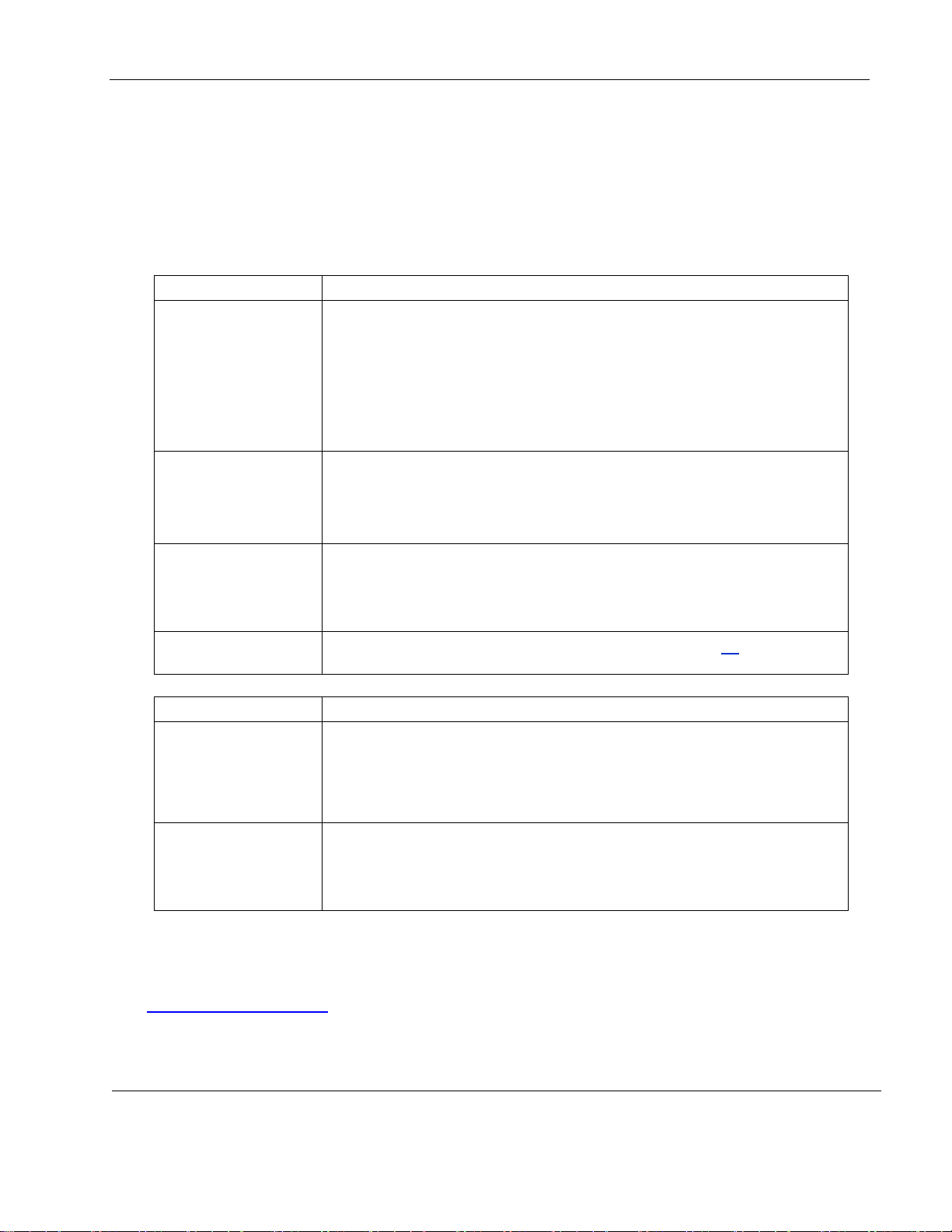
Problem
Possible Solutions
No video
Verify that the video source is on and has a tape or DVD installed.
Verify that a signal is reaching the display by using an oscilloscope or
another display.
Verify that the display is turned on (LED is green).
Verify that the pinout is correct.
Verify that the video input (Analog RGB/DVI/Composite) and video
standard (NTSC/PAL/SECAM/RS170) match your application.
Screen is black
Verify that the display is receiving power.
Verify that the pinout is correct.
Verify that the video source is on and has a tape or DVD installed.
Verify all connections.
Screen is blue
Verify that a signal is reaching the display by using an oscilloscope or
another display.
Verify that the pinout is correct.
Verify that the video source is on and has a tape or DVD installed.
Color is Out of
Adjustment
Refer to the OSD Main Menu options described on page 27.
Problem
Possible Solutions
Image flickers
Verify that the signal cable is secure.
Verify that the vertical frame frequency is 75 Hz or less. If using the
display with a PC in Windows, go to Control PanelDisplay Properties
and change the Display Control Panel to 60 Hz to achieve the best
performance.
Image is distorted
Verify pinouts.
Verify that a signal is reaching the display by using an oscilloscope or
another display.
Examine the display for pinched or damaged cables.
8. TECHNICAL REFERENCES AND SUPPORT
If the display does not function properly, refer to the following troubleshooting table for symptoms
and possible solutions before contacting Rosen field support.
Always use an oscilloscope to verify the video signal
Always use a multimeter to verify voltages
Check actual results against the requirements described in this manual
8.1. Technical Support
For field support or to order parts, contact Rosen Aviation at 888.668.4955, or visit
www.rosenaviation.com.
Page 33
Rosen Aviation 20‖ SlimLine II Display
Document Number: 9002645
Revision: K
Date: 9/24/09
Template: 4.2-3-6-FM; Revision D; 13 March 2008 Page 33 of 34
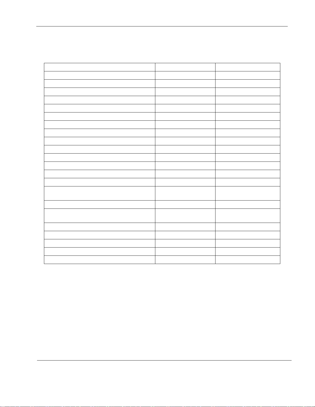
Description
DO-160D Section
DO-160D Category
Temperature and Altitude
4.0
A1
Temperature Variation
5.0
C
Humidity
6.0
A
Operational Shock & Crash Safety
7.0
B
Vibration
8.0
SB
Explosion Proofness
9.0
N/A
Waterproofness
10.0
N/A
Fluids Susceptibility
11.0
N/A
Sand & Dust
12.0
N/A
Fungus Resistance
13.0
N/A
Salt Spray
14.0
N/A
Magnetic Effect
15.0
A
Power Input
16.0
AB
Voltage Spike
17.0
B
Audio Frequency Susceptibility — Power
Inputs
18.0
Z
Induced Signal Susceptibility
19.0
Z
Radio Frequency Susceptibility (Radiated &
Conducted)
20.0
TT
Emission of Radio Frequency Energy
21.0
M
Lightning Induced Transient Susceptibility
22.0
N/A
Lightning Direct Effects
23.0
N/A
Icing
24.0
N/A
Electrostatic Discharge
25.0
A
9. DO-180D QUALIFICATIONS
DO-160D Test criteria to which we test the 2002 series displays
Page 34
Rosen Aviation 20‖ SlimLine II Display
Document Number: 9002645
Revision: K
Date: 9/24/09
Template: 4.2-3-6-FM; Revision D; 13 March 2008 Page 34 of 34
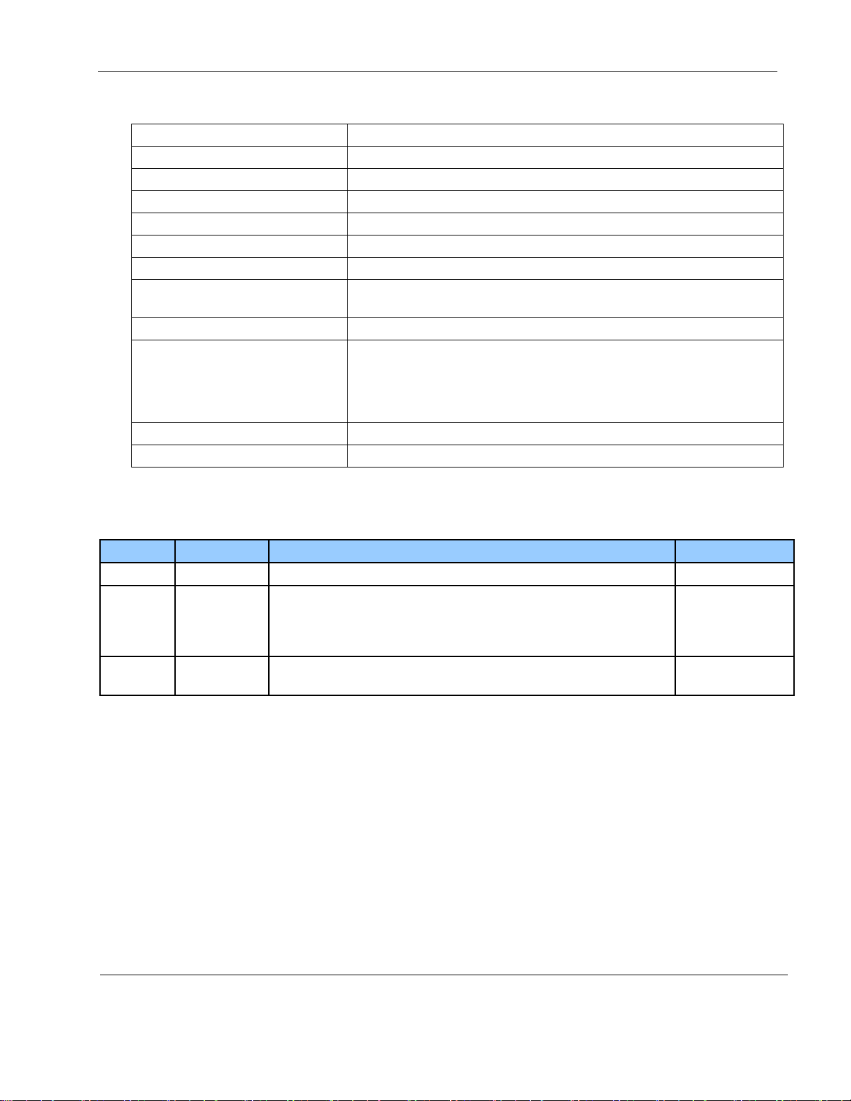
Size
16.17 x 12.15 inches [410.7 x 308.6 mm]
Resolution
1600 w x 1200 h (UXGA)
Viewing Angle (H/V)
±85/85°
Brightness
300cd/m
2
typical
Contrast Ratio
600:1 typical
Backlight Lamp Life
50,000 hours
Weight
12.85 lbs ± 5% [5.83 kg]
Dimensions
18.19‖ (W) x 14.86‖ (H) x 2.10‖ (D)
[462.03 mm (W) x 377.44 mm (H) x 53.34 mm (D)]
Power Requirements
1.9A ± 5% 28VDC
Video Performance
Video Standards
Graphics Standards
Video Input
NTSC, PAL, SECAM, RS170
VGA, through UXGA (75 Hz max)
1Vp-p, 75 ohms
Operating Temperature
0ºC - 50ºC
Warranty
2-year
Revision
Date
Revision Description
EC
H
12/31/08
Update format, add OSD changes to match firmware
08534
J
6/8/09
Change time taken to store memory to 10 seconds, add note
that special filter, when enabled, disables OSD menu, add note
to Section 5.3 picture submenu, Section 5.5 utility submenu,
and update Section 6 PIP info.
09205
K
9/24/09
Replace incorrect controller number 0300-402 with 0300-408,
Section 1.1 Unpacking
09387
9.1. Specifications
10. REVISION HISTORY
 Loading...