

Page 1

Page 2
Table of Contents
Section Page
1. Quick Reference Guide 2-3
2. About the Milan System 4-5
3. Installation of the Milan 6-11
4. Using the Remote Control 12-13
5. Set-up kit 14
6 Exploded view drawing 15
7. Troubleshooting 16
8. Notes 17
9. Specifications 18
Page 3
1 Milan Quick Reference Guide
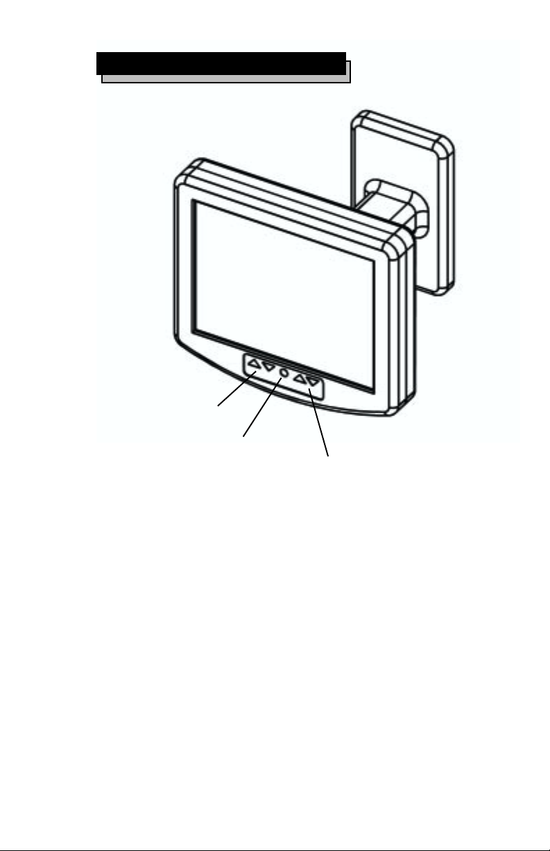
Channel Up/Down
Power
Power
Depress the power button on either the remote or
the front of the monitor to power the Milan .
Switching Channels
Using either the remote control or the buttons on
the front of the monitor, switch the channels
up or down as desired.
Volume Up/Down
Page 2
Page 4
1 Milan Quick Reference Guide
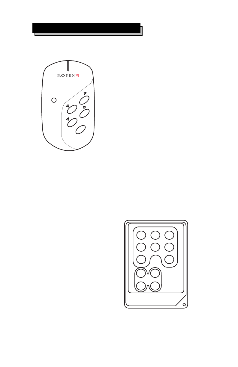
The user remote is used for
day-to-day operation. The user
remote has the following
functions.
POWER
CHANNEL
VOLUME
MUTE
Please refer to Section 4,
Using the Remote Control, for
further details.
The intent of the master remote is
to set-up the monitor for end user
operation. It has all of the
features of the user remote with
the addition of the following
controls:
Contrast
Color
Bright
Volume Up/Down
Mute
Channel Up/Down
Power On/Off
MUTE
EDIT
CONTRAST
ADD/DEL
POWER
COLOR BRIGHT
AUTO PROG
Edit
Auto Program
Add/Del
Please refer to Section 4, Using
the Remote Control for further
details.
Page3
CHANNEL
RC-02
VOLUME
Page 5
2 About your Milan
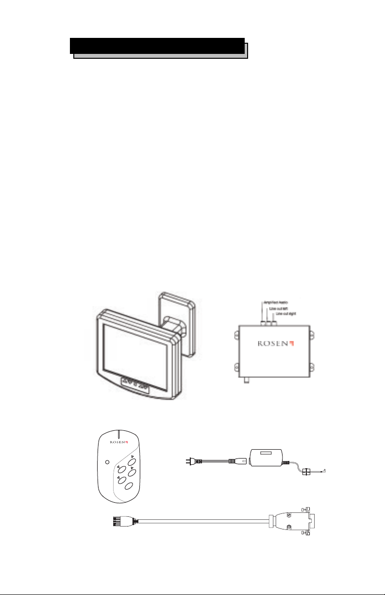
Your Rosen Milan system has the following
components:
A 6.8 color LCD flat-panel display (FPD)
mounted within an aluminum swing-arm
assembly. (see figure 1)
A Separate Tuner Module. (see figure 2)
A User Remote Control. (see figure 3)
A Signal Cable. (see figure 4)
A Power Converter (see figure 5)
Figure 1 Figure 2
Amp
Audio
out
L
R
Line
Out
Tuner Module
Part # 9200-0101-020
Power
12 volt
POWER
Figure 3
CHANNEL
VOLUME
TE
U
M
Page 4
Cable In
Monitor out
Figure 5
Figure 4
Page 6

2 About your Milan (cont.)
Signal Cable
When routing the signal cable from the FPD
junction box to the tuner location, note the
cable has different connectors on each end. The
silver D-9 connector goes to the FPD, while the
molded RJ-45 connector goes to the tuner
module. Since the D-9 is larger than the RJ-45,
you way want to take this into account when
routing the cable through tight spots.
IMPORTANT: The RJ-45 connector has a locking
plastic tab. This tab is usually protected by a
molded rubber cover built into the cable. However,
if too much force is used when routing the cable
through a tight spot, it is possible for this tab to
hang up. If the installer uses too much
force in this situation, the tab could break. Use
care when routing cables through tight spots.
Power Adapter Cable
Plug the power cord into a 110V 60 Hz AC outlet.
The system consumes about 12 watts while in
use.
IMPORTANT: Ensure that this power cord is
routed safely and in accordance with any local
regulations.
Coaxial Cable
Screw the threaded coaxial fitting onto the
threaded fitting on the tuner module. Do not kink
the coaxial cable, and avoid sharp bends, which
places stress on the connectors.
Page 5
Page 7

3 Installing Your Milan (cont.)
3 Installing Your Milan
A. Getting Started
Locate the desired placement of the component
to ensure the monitor has enough room for
desired movement.
Warning:
Excessive moisture and condensation will
damage the unit. Be sure your chosen location
for the tuner module and monitor are in a clean
dry area.
Ensure there is a wall plug within 2 of desired
tuner module location before mounting any
components.
The tuner module should be mounted on a flat
solid surface. Do not mount on an uneven
surface. Doing so will cause damage to the unit.
The base of the arm mounts to the standard
screw holes provided in a single-gang junction
box.
Make sure that your j- box is securely
fastened to the wall. If using a cut-in-style
j-box, additional bracing may be required.
Page 6
Page 8

3 Installing Your Milan (cont.)
3 Installing Your Milan
B. Mounting of Components
Locate the mounting holes on monitor base.
anodized trim plate
steel mounting
mounting screws
plate
5
mounting footprint
Route signal cable from tuner module to
junction J-box
Plug pigtail from monitor into signal cable in
J-box.
Coil excess (service loop) wire in J-box and mount
monitor using supplied screws.
Replace trim plate.
Test for stability and desired range of motion.
3.3
single-gang junction
box in wall
3
Page 7
Page 9
Installing Your Milan (cont.)
B. Mounting of Components (cont)
NOTE: The screws used to mount the arm to the
junction box could vary in length depending on the
style of installation, and thus are not included in the
kit. Before mounting the FPD assembly, remember
to connect the silver D-9 connector to the signal
cable and tighten the backshell retainer screws
C. Installing Tuner Module
Place tuner module in desired location.
Mounting the tuner module is done with four
installer-supplied screws. Before mounting the
tuner module, make sure that all required cables
will reach your chosen location. Also make sure
that there is sufficient clearance on the sides for
all the connectors to properly plug into the tuner
module.
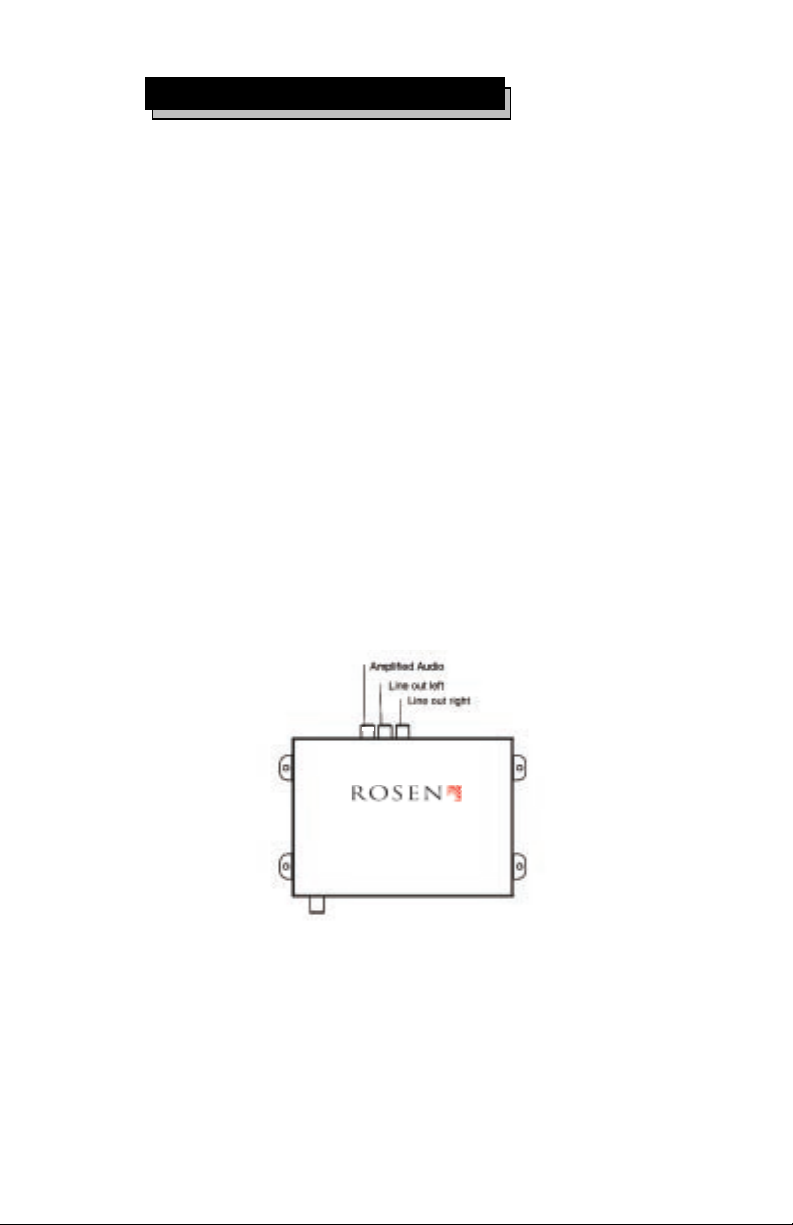
Amp
L
Audio
Line
out
Tuner Module
Part # 9200-0101-200
Cable In Monitor out
R
Out
Page 8
Power
12 volt
Page 10

3 Installing Your Milan (cont.)
The Tuner Module requires the following
connections:
Plug in 20-foot signal cable from the FPD
assembly Monitor out jack on tuner
module.
Plug in 10-foot power adapter cable to wall plug
Connect cable TV coax cable ( installer-supplied
RG59 coaxial cable with Type F connector,
carrying the CATV signals) to cable in jack on
tuner module.
Either the mono 2-watt audio output to a speaker
(using the single yellow female RCA connector) or
the stereo line-level outputs to an installer
supplied amplifier (white female RCA for left, red
female RCA for right).
D. Wiring the Audio Outputs
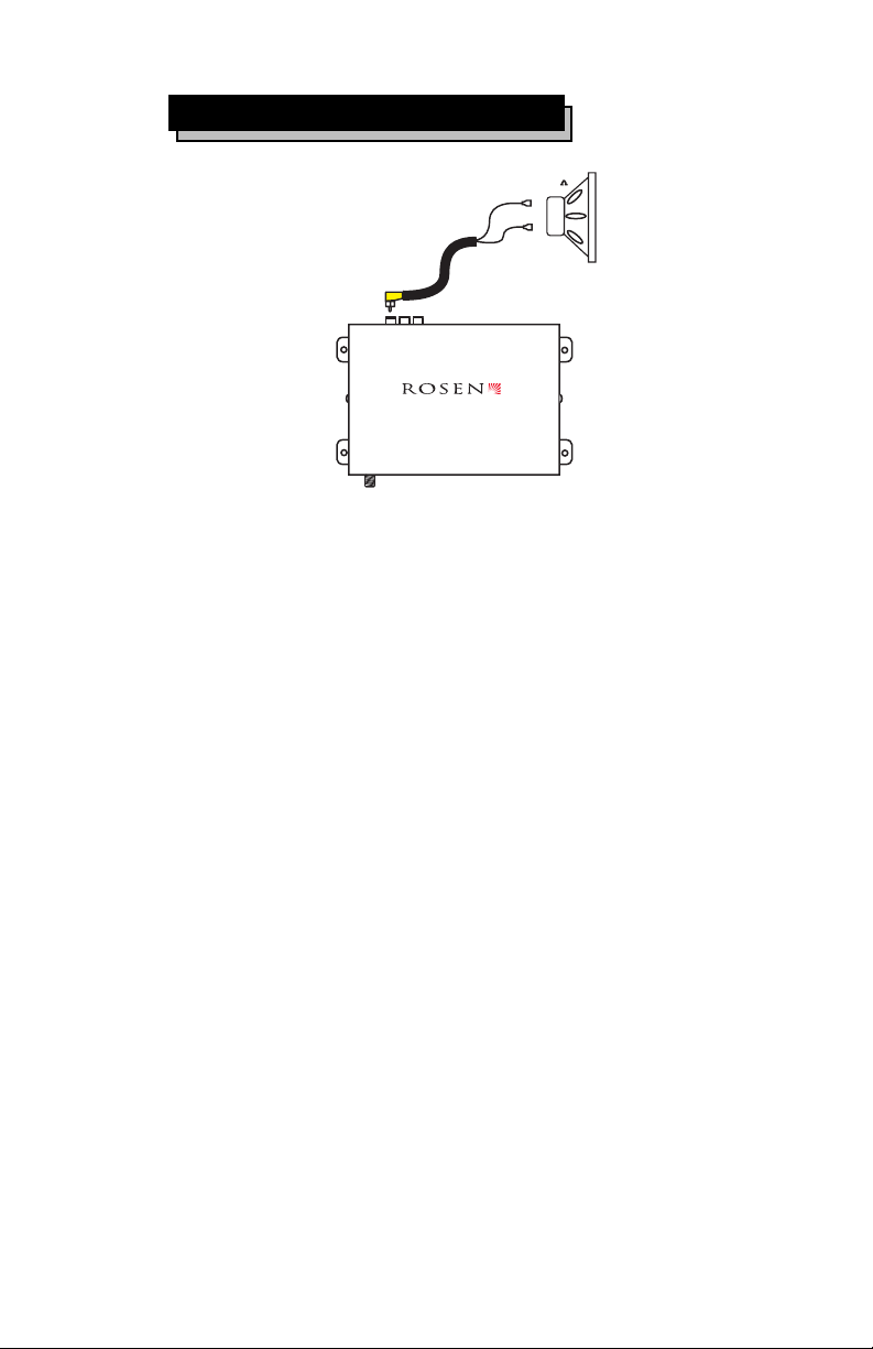
Using the built-in mono amplifier
The onboard amplifier is rated to produce 2 watts
into an 8 Ohm load. If more power is required, or if
stereo sound is required, use an outboard
amplifier as described below.
To use the onboard amplifier, a male RCA jack
must be installed onto the speaker wire. Use the
centerpin for the (+) lead, and the outer shield for
the (-)lead of the speaker. Plug this connector into
the yellow female RCA jack on the side of the
tuner module.
Page 9
Page 11
3 Installing Your Milan (cont.)
D. Wiring the Audio Outputs (cont.)
Installer supplied
+
RCA cable
AMP
L
R
AUDIO
LINE
OUT
OUT
CABLE IN MONITOR OUT
Tuner Module
Part # 9200-0101-200
POWER
12 VOLT
NOTE: This output is not rated for speaker loads
lower than 4 Ohms.
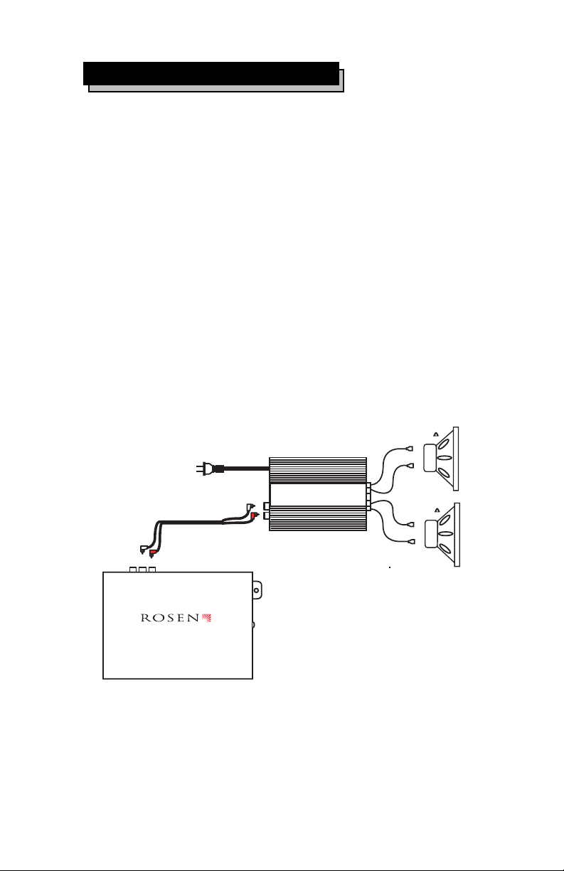
Using an outboard stereo amplifier.
The red and white line-out RCA jacks deliver a 1V
signal. Use standard RCA jacks (not included) to
send the signal to your optional amplifier.
IMPORTANT: The line-level outputs are fixed
output voltages. This means that the VOLUME UP
and DOWN controls on the remote and on the FPD
front panel do not affect these outputs. When these
outputs are used, some other form of volume control
must be provided by the installer.
Installer
8
supplied
-
speakers
Page 10
Page 12
3 Installing Your Milan (cont.)
D. Wiring the audio outputs ( cont. )
NOTE: Some amplifiers could generate interference
which could interfere with the video signal. Should
this occur, it is often due to the tuner module being
placed too closely to the amplifier, or the TV signal
cable being routed too closely to the amplifier.
Should video interference occur, confirm that it is
associated with the amplifier by disconnecting the
amplifier and rechecking for the problem. If it
remains, experiment with relocation of the
components, or replace the amplifier with one which
is more appropriate for video applications.
Installer-
supplied RCA
cable
AMP
L
R
AUDIO
LINE
OUT
OUT
Tuner Module
Part # 9200-0101-200
Installer-supplied
amplifier with volume
control provision
AMPLIFIER
POWER
12 VOLT
Installer-supplied
speaker wire
Installersupplied
speakers
8
+
-
8
+
-
Page 11
Page 13
4 Using the Remote Control
3 Installing Your EM1
End User Remote Operations
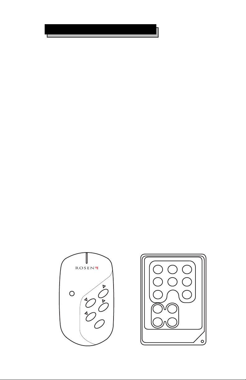
The end user remote has four basic functions.
These functions include:
MUTE - when this button is pushed it will reduce
the volume to zero and display MUTE in the upper
right hand corner of the display. Pushing the
button again will return the volume to the previous
volume setting.
POWER - This button controls the main power of your
Milan. Pressing the button once will turn the power
on. Pressing the button again will turn the power off.
CHANNEL- The up and down arrows will navigate you
through different stations in the TV and CATV
modes. The selected channels will be displayed in the
upper right corner of the monitor.
VOLUME - The up and down arrows will control the
volume. The volume settings are from 0 (no volume)
to 16 (maximum volume). Pushing the buttons once
will move the volume in one step increments. Holding
the buttons down will gradually increase or decrease
volume until the button is released.
End user remote
POWER
CHANNEL
VOLUME
MUTE
Page 12
Master remote
(see page 13)
MUTE
EDIT
COLOR BRIGHT
CONTRAST
ADD/DEL
CHANNEL
RC-02
AUTO PROG
VOLUME
POWER
Page 14

4 Using the Remote Control
3 Installing Your EM1
Master Remote Operations
The master remote has all the features of the end user
remote plus five set up features. These features
include:
CONTRAST - Contrast has a scale from 0 (lowest
setting) to 16 (highest setting). The factory default is
set at 8. To change the contrast push the CONTRAST
button once. This will display a scale on the bottom
middle of the screen, Use the VOLUME up and down
arrows to select the desired setting.
COLOR - The color setting has a scale from 0 (lowest
setting) to 16 (highest setting). The factory default
setting is at 8. To change the color push the image
brightness button once. This will display a scale on the
bottom middle of the screen. Use the VOLUME up
and down arrows to select the desired setting.
BRIGHT - The brightness setting has a scale from 0
(lowest setting) to 16 (highest setting). The factory
default setting is at 8. To change the color push the
BRIGHT button once. This will display a scale on the
bottom middle of the screen. Use the VOLUME
up and down arrows to select the desired setting.
EDIT - The edit button will allow you to customize your
TV and CATV channel selections. To delete a channel
from one of these modes, select the channel you wish
to delete. Push the EDIT button once, then push the
EDIT button once more to confirm selection.
AUTO PROGRAM - The auto program feature will
automatically detect signal and select them as viewable channels in the TV and CATV mode. Pushing
the AUTO PROGRAM button once will bring up the
menu. You can choose between STD, IRC, and HRC
cable format by using the CHANNEL up and down
arrows. Once the format has been established, push
the AUTO PROGRAM button once to confirm.
Page 13
Page 15
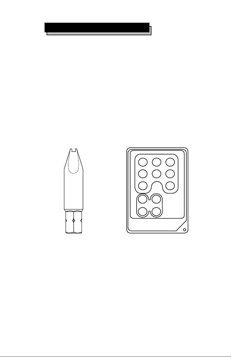
5 Set-up kit
Your Rosen Set-up kit has the following
components:
Driver spanner tool ( figure 1)
Master remote ( figure 2)
Figure 1
EDIT
CONTRAST
ADD/DEL
CHANNEL
RC-02
Figure 2
MUTE
COLOR BRIGHT
VOLUME
POWER
AUTO PROG
Page 14
Page 16
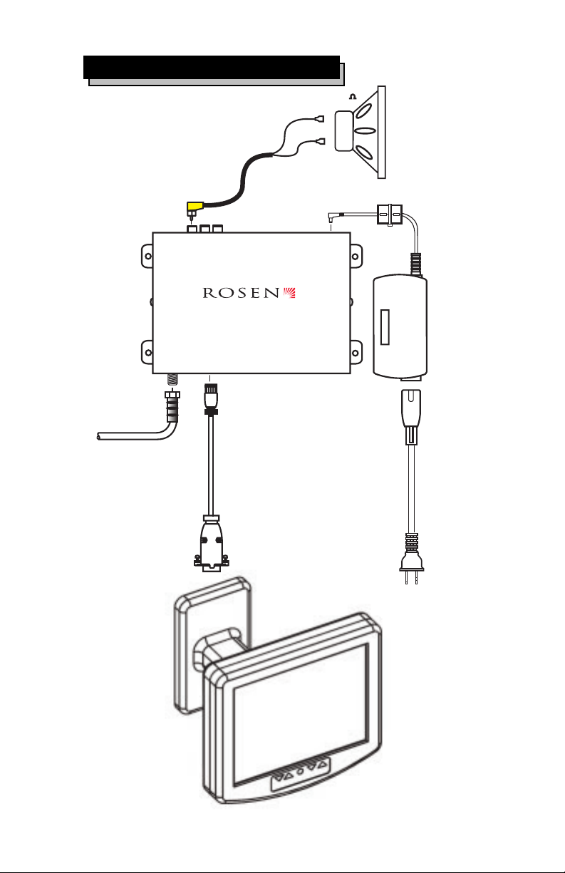
6 Exploded View Drawing
AMP
L
R
AUDIO
LINE
OUT
OUT
Tuner Module
Part # 9300-0101-020
CABLE IN MONITOR OUT
House cable
8
+
-
POWER
12 VOLT
Page 15
Page 17

7 Trouble Shooting
3 Installing Your EM1
This section provides a brief trouble shooting
guide. Please call Rosen Technical Support
at 888-883-2790 for additional information and
technical support.
NO AUDIO - Check volume level.
Check MUTE button.
If using audio line output, verify
external audio amplifier is on and
functional.
NO VIDEO - Check Brightness, Color and
Contrast settings.
Check Cable in for proper format
(STD, IRC , or HRC).
Verify channel selected
NO POWER - Press the power button on the
remote or monitor.
Verify Power supply is plugged in.
Verify 120 vac outlet has power
NO REMOTE - Check batteries
Page 16
Page 18

8 Notes
Page 17
Page 19

9 Specifications
Screen size: 6.8 LCD
Power: 110V 60 Hz AC at 12 Watts.
RF signal input: 75 ohm coaxial from cable
TV. STD, IRC, and HRC formats.
Type F connector.
Video signal: Composite NTSC 1Vp-p 75 ohm
load and proprietary digital control interface
Line out audio signal: Stereo audio signal 1V
peak-to-peak, into a 100K ohm input.
Amplified audio signal: mono signal 2-watt
per channel into 8 ohms
Dimensions
(W) 7 3/16
(L) 6 7/8
(H) 6
Weight 3.2 lbs
FCC Statement: This equipment has been tested
and found to comply with the limits for a Class B
digital device, pursuant to part 15 of the FCC Rules
Note: Please contact Rosens Technical department for
installer recommendations
Page 18
Page 20

 Loading...