

Page 1

6500
6500
6.5
Model Number
DISPLAY
DISPLAY
SlimLine
Document # 9002751 Rev D
Compliant to DO-160D
CORPORATE OFFICEOEM SALES DEALER & OPERATOR SALES
1020 Owen Loop South
Eugene, OR 97402
1-888-668-4955
Fax (541) 342-4912
8 Shackleford Plaza,
Suite 201
Little Rock, AR 72211
1-888-523-7523
Fax (501) 225-1015
1121 Warren Ave, Suite 240
Downers Grove, IL 60515
1-800-859-5058
Fax (630) 963-4405
www.
rosenaviation
.com
www.
rosenaviation
.com
9002751
Page 2

6.5” SlimLine LCD Page 1
Table of Contents
Introduction and Display Overview...................3
Pinouts ................................................................4
Installation Guidelines........................................6
Operation ............................................................8
T echnician Mode.....................................................14
Troubleshooting ...............................................16
Technical Support ............................................1 7
Specifications ...................................................18
Disclaimer .........................................................19
Page 3

1020 Owen Loop South
Eugene OR 97402
541-342-3802
www.rosenaviation.com
Page 4

6.5” SlimLine LCD Page 3
Introduction and Display Overview
Introduction and Display Overview
Welcome to the 6500 T echnical Manual for the 6.5" LCD
display . This manual provides an overview of the following
information:
• Pinouts
• Installation
• Operation
• T echnician Mode
• Troubleshooting
• Specifications
The 6500 base model includes the following features:
• T wo Y ear W arranty
• 6.5” Diagonal Screen
• 400 NIT Brightness
• 6.91” (W) x 5.90” (H) x 1.18” (D)
• Brightness, Hue, Saturation, and Contrast
Adjustments
• NTSC/P AL/SECAM/RS170 (B&W) Video S tandards
• 640 x 480 Screen Resolution (VGA )
• On Screen Display (OSD) Functions
• S tatus LED
• 28 V olt DC Power Operation
• Front Panel Menu Operation
The 6500 series monitor offers the following options:
• Center , Right, Left Mount Arm with Plug-in® Mini-Base
Receptacle
• Video Source Select Switch
• Pogo Pin Plug and Base Assemblies
Page 5
Page 4 Rosen Aviation Displays
Warning!
This Display is for Entertainment
Purposes Only! Connect to the Non-
Critical Power Bus.
Pinouts
Pinout descriptions are provided to assist in the wiring
process. Pay close attention to the pinout information while
completing wiring connections.
Main Interface Connectors
The 6.5 SlimLine has either one or two main interface
connectors, depending on the SlimLine base receptacle
model you purchased. The following tables list main
interface connectors and mating connectors per base
receptacle model.
SlimLine Base Receptacle Models:
0100-002, 0100-004, 0100-041, and 0100-042
Connector: 9 Pin Male D-Subminiature
Mate: 9 Pin Female D-Subminiature
Rosen Connector Kit part number 0300-022
Pin # Monitor Signal
1 Chassis Ground
2 +28V DC
3 DC Return
4 Select Switch*
5 Select Switch Return*
6 Reserved
7 Video Signal Input
8 Video Ground
9 Reserved
Pinouts
*Pins 4 and 5 connect to a momentary relay switch for
external control. For example, it can be connected to a
cabin management system for video source switching.
Page 6
6.5” SlimLine LCD Page 5
Pinouts
SlimLine Base Receptacle Models:
0100-005 and 0100-040
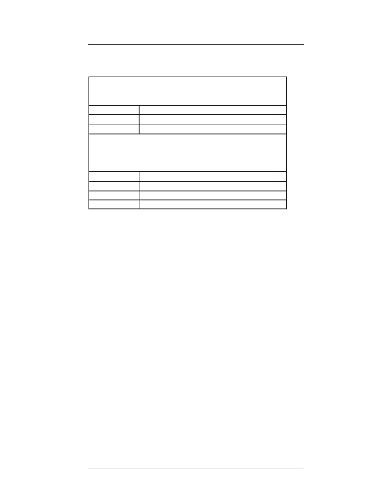
Video Connector: BNC Jack, AMP part number 221199-5
Mating Video Connector: BNC Plug, AMP part number
221185-8
PP
PP
Pin # Monitor Signal
BNC signal Video Signal
BNC shield Video Return
Power Connector: Female 3 pin, .062" Molex
Mating Power Connector: Molex 03-06-2033
Mating Power Contact: Molex 02-06-2103
PP
PP
Pin # Monitor Signal
Molex 1 +28V DC
Molex 2 DC Return
Molex 3 Reserved
Page 7
Page 6 Rosen Aviation Displays
Installation
Installation Guidelines
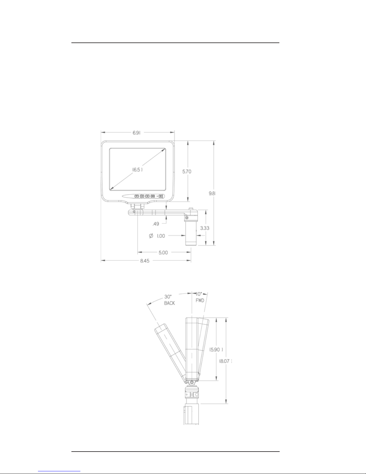
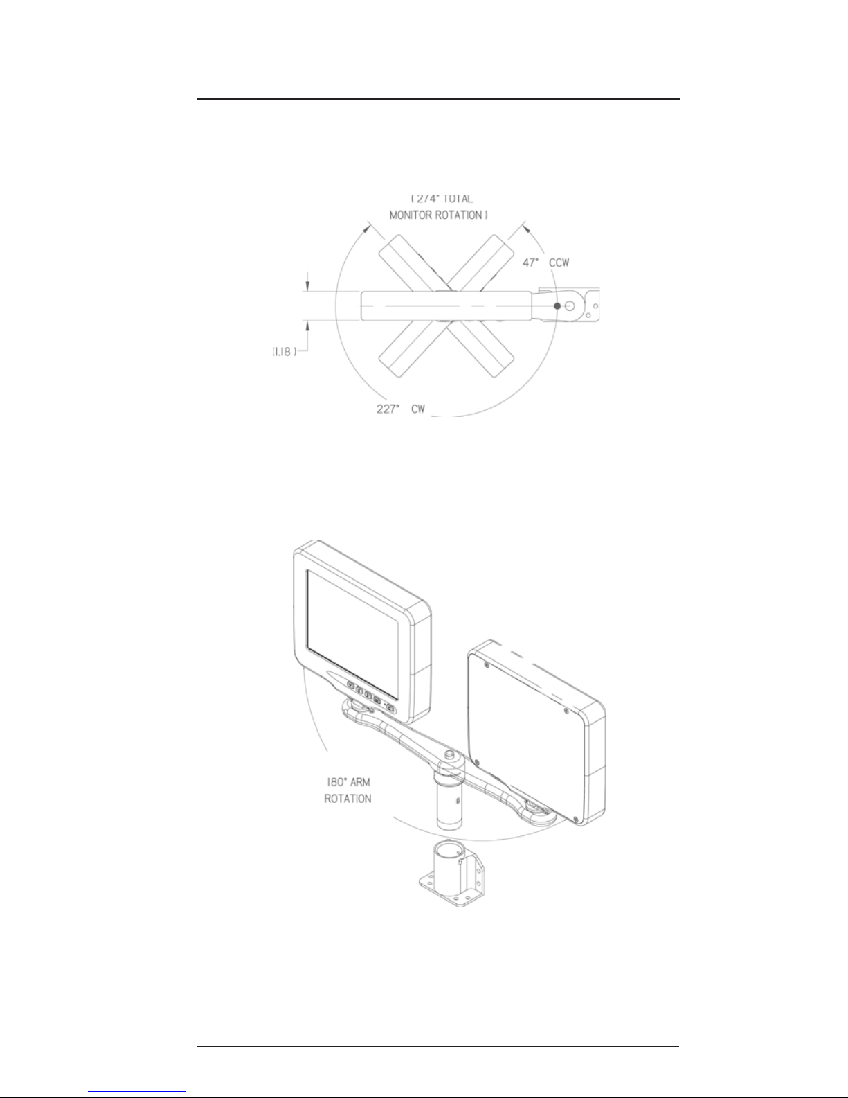
The following drawings are provided to assist the installation
process for your 6.5 display. Pay close attention to
dimensions and rotations when considering installation
requirements.
Note: The dimensions listed are listed in inches.
Page 8
6.5” SlimLine LCD Page 7
Installation
Page 9
Page 8 Rosen Aviation Displays
Operation
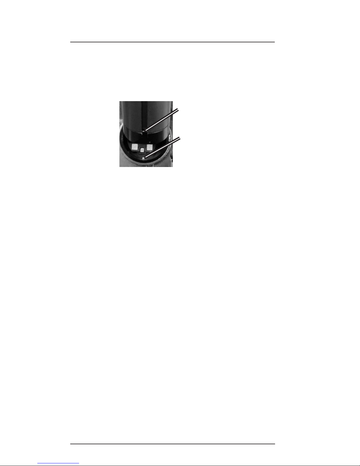
Ensure that when plugging the arm into the base receptacle,
the set screw in the base follows the arm’s keyed slot and the
connection is not forced.
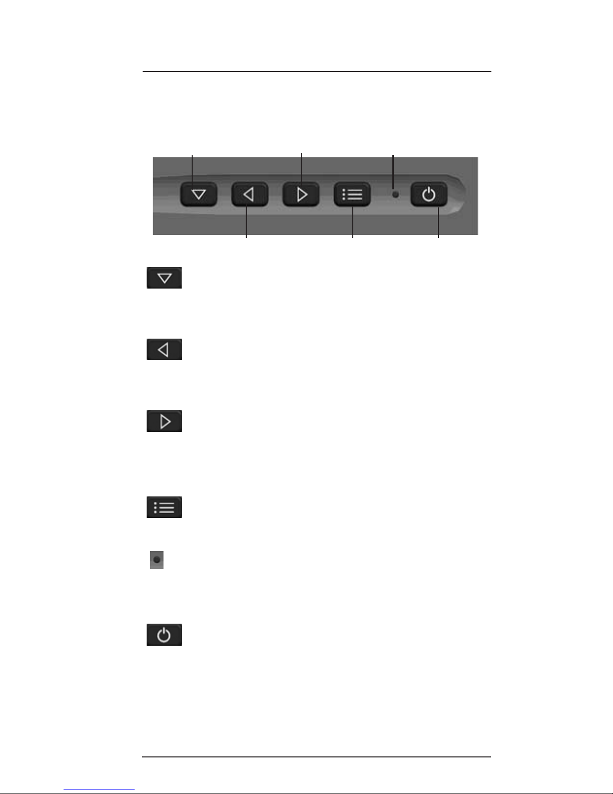
Use the buttons on your 6.5” Display to control screen setup
and choose between video source options.
Buttons and screen options are defined in this section on
page 9.
Operation
Slot
Set Screw
Page 10
6.5” SlimLine LCD Page 9
Select Switch/
Menu Scroll
Decrease Value
Sub-Menu Scroll/
Increase Value
OSD ON/OFF
Power ON/OFF
S tatus LED
Select Switch/Menu Scroll: Press this button to
switch between video source options , or to scroll
down when viewing On Screen Display (OSD) menu
options.
Decrease V alue: Press this button during normal
operation to decrease backlight intensity . When
using the OSD, press this button to decrease an
OSD menu’s range value.
Sub-Menu Scroll/Increase Value: Press this
button during normal operation to increase backlight
intensity. When using the OSD, press this button to
scroll to an OSD sub-menu when available, or use it
to increase an OSD menu’s range value.
OSD ON/OFF: Press this button to display the OSD
Main menu. Pressing the button again will remove
the OSD menu from the screen.
Status LED: The St atus LED shows red when the
display is in standby mode, green when the display
is active, and amber when the Select Switch is
pressed.
Power ON/OFF: Press this button to turn the
display ON or OFF.
6.5" Display Button Functions
Display buttons are shown and defined below .
Operation
Page 11
Page 10 Rosen Aviation Displays
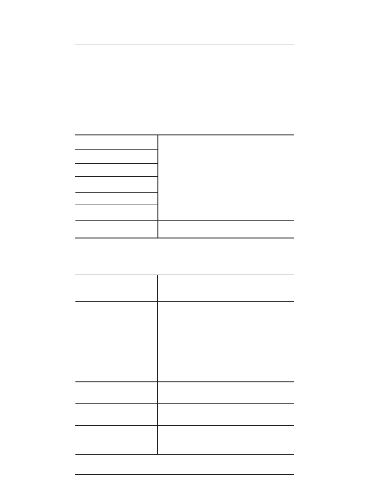
OSD Time-Out Use display buttons to adjust the
range of time that elapses before a
menu will time-out
Power Up Use display buttons to select
Auto-on, Auto-of f, or Restore.
Choose Auto-on to have the display
turn ON when power is applied.
Choose Auto-off to have the display
go into Standby mode when power is
supplied. Choose Restore to have the
display return to its last power-ON
status if power is interrupted
RGB Auto Detect This Option is not available with this
Display
Restore Defaults Select this option to restore factory
default settings
Video Formats Scroll to this selection’s sub-menu to
view video format options (shown on
the next page)
Advanced Menu
Options Description
Operation
On Screen Display (OSD) Main Menu
The On Screen Display (OSD) provides a set of menus that
enable users to adjust or view screen setup features. Some
Main menu selections lead to submenus with additional setup
options. Press the OSD ON/OFF button to view the Main
menu. Main menu options are described below , and then
available sub-menus are listed in the tables that follow .
Main Menu Options Description
Brightness
Contrast
Color
Tint
Sharpness
Backlight Dimming
Advanced Menu Use display buttons to access the
Advanced menu’s sub-menu
Use display buttons to increase or
decrease these options’ range values
Page 12
6.5” SlimLine LCD Page 11
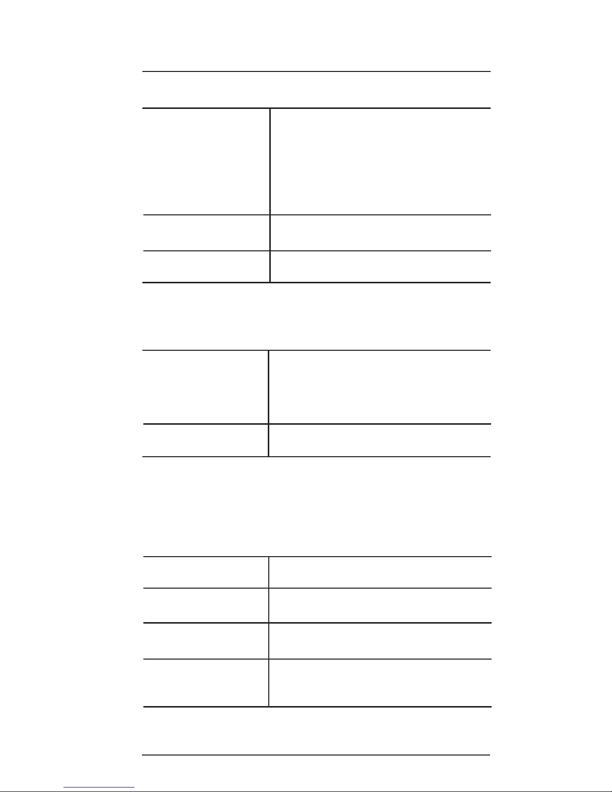
Hours This option displays the hour and
minutes of the display’s life
SW R ev This option displays the current
software revision
Power Cycles This option displays the number of
times power has been cycled
Source This option displays the current
selected video standard (NTSC/P AL/
SECAM)
Select Switch Adjust Relay Active T ime to set the
time delay when pressing the Select
Switch to change video sources
Adjust Repeat Delay to set the time
delay when pressing and holding the
Select Switch to change video
sources
Monitor Info Scroll to this selection’s sub-menu to
view monitor information (see below)
Back Select this option to return to the
Advanced menu
Operation
Advanced Menu
Options Description
Video Formats
Sub-Menu Options Description
Use display buttons to select
between the two choices of auto
detection. The Display will
automatically detect and switch to
the input video standard*
Back Select this option to return to the
Advanced menu
Monitor Info
Sub-Menu Options Description
NTSC/PAL/SECAM
or
NTSC/P AL Only
continued...
*If the image is black and white when switching from SECAM
to P AL video st andard, press the Select switch
Page 13
Page 12 Rosen Aviation Displays
Current T emperature This option displays the most recent
temperature reading within the
display . Temperature readings update
approximately every 30 seconds
Av g Temp This option displays the average of
approximately the last eight current
temperatures
Max Temp This option displays the highest
temperature ever recorded within the
display
Min Temp This option displays the lowest
temperature ever recorded within the
display
Over T emp This option displays the number of
over-temperature shut downs that
have occurred.
*A safety feature shuts down the
monitor if it reaches or exceeds 140
degrees Fahrenheit
Operation
Temperature
Sub-Menu Options Description
T emperature Menu Scroll to this selection’s sub-menu to
view monitor temperature information
(shown below)
Signal Level This option will show Low, Good, or
High. If the signal shows Low or
High, adjust the video level at the
source
Back Select this option to return to the
Advanced menu
Monitor Info
Sub-Menu Options
Continued... Description
continued...
Page 14

6.5” SlimLine LCD Page 13
Under T emp This option displays the number of
under-temperature shut downs that
have occurred.
*A safety feature shuts down the
monitor if it reaches or drops below
32 degrees Fahrenheit
Back Select this option to return to the
Monitor Info sub-menu
*If an Over T emp or Under T emp shut down occurs,
T emp Shutdown is shown on the OSD for approximately 30
seconds, and then the display shuts off until the temperature
reaches acceptable temperature limits. The display will
then automatically turn back on.
Temperature
Sub-Menu Options
Continued... Description
Operation
Page 15

Page 14 Rosen Aviation Displays
Technician Mode
Technician mode provides the ability to customize and restrict
access to the Main menu for specified options. This section
describes how to enter , enable and disable options, and exit
T echnician mode.
Entering Technician Mode
Complete the following list to enter Technician mode:
1 Apply 28V to the display and wait until the
status LED turns green (if the display is in
auto-off, press the power ON/OFF button).
2 Once the status LED turns green, press the
power button to turn it off.
3 Press and hold the power button down for 10
seconds before releasing it (more than 10
seconds is OK).
4 Press the OSD ON/OFF button and confirm that
the word On or Off is shown to the left of each
menu option in the Main menu. This verifies that
the display is in Technician mode.
Main menu options when starting Technician mode:
On Brightness
On Contrast
On Color
On Tint
On Sharpness
On Backlight
Off Advanced >>
Enabling/Disabling Individual Menu Items
Use the display buttons per normal operation to navigate
through menu options. Adjust the menu options as desired
and then enable or disable the option for users as desired.
Disable a menu option as follows:
1 Highlight the desired menu option.
2 Press and hold the Select switch in for 5
seconds.
3 Release the Select switch; the next option
becomes highlighted and the word OFF appears
next to the disabled menu option.
Technician Mode
Page 16

6.5” SlimLine LCD Page 15
Enabling/Disabling Individual Menu Items
Continued...
Enable a menu option as follows:
1 Highlight the desired menu option.
2 Press and hold the Select switch in for 5
seconds.
3 Release the Select switch; the next option
becomes highlighted and the word ON appears
next to the enabled menu option.
When the monitor is returned to normal mode, any items
which were disabled in technician mode will no longer be
available in the main menu. It is possible to disable all Main
menu items; in this case there will be no user accessible
functions in the Main menu.
Note: the Increase and Decrease V alue buttons will not work
to adjust menu options disabled in Technician mode.
Below is an example of how adjustments in Technician mode
affect the appearance and options within the normal Main
menu.
Technician Mode
Main Menu:
On Brightness
On Contrast
On Color
Off Tint
Off Sharpness
Off Backlight
Off Advanced
Normal Mode
Main Menu Options:
Brightness
Contrast
Color
Exiting Technician Mode
To exit the Technician mode, simply turn the power off and
on again either with the power button or through the 28V
supply.
Technician Mode
Page 17

Page 16 Rosen Aviation Displays
Troubleshooting
Troubleshooting
If the monitor does not function properly , refer to the following
troubleshooting table for symptoms and possible solutions
before contacting Rosen field support.
Notes:
• Always use an oscilloscope to verify the video signal
• Always use a multimeter to verify voltages
• Check actual results against the requirements
described in this manual
PROBLEM POSSIBLE SOLUTION
No power Verify that the pinout is correct . Push
and hold the power switch for about one
second.
V erify Monitor is fully inserted into base
receptacle.
No video on V erify that the pinout is correct.
screen
V erify that the video source is on and has
a tape or DVD installed.
V erify video signal at monitor end, Use an
oscilloscope or another monitor .
Screen is V erify that the monitor is getting power
(green LED on) and the pinout is correct.
V erify that the video source is on and has
a tape or DVD installed.
V erify all connections
Screen is blue V erify signal at monitor end, Use an
oscilloscope or another monitor .
V erify that the pinout is correct.
V erify that the video source is on and has
a tape or DVD installed.
black
Page 18
6.5” SlimLine LCD Page 17
Troubleshooting
Red LED is on Monitor is connected to 28 volts but is
either switched off or is not receiving a
video signal (St andby mode)
An over temp or under temp occurred
(see pages 1 1 and 12)
Image is distorted V erify that the pinout is correct.
Use the OSD Monitor Info sub-menu to
verify that a signal is present and not too
high or low (see page 1 1)
Examine system for pinched or damaged
cables
Image is black
and white when
switching
between SECAM
and P AL
PROBLEM POSSIBLE SOLUTION
Technical Support
For field support or to order parts, contact Rosen Aviation
Displays at: 1-888-668-4955
or visit us at: www .rosenaviation.com
If the image is black and white when
switching from SECAM to P AL video
standard, press the Select switch
Page 19

Page 18 Rosen Aviation Displays
Specifications
Specifications
LCD Performance
Screen Resolution (pixels) 640 w x 480 h
Display V iewing Area 5.14 x 3.84 in
Viewing Angle ( At contrast ratio 10:1 )
Horizontal ±50º
V ertical +35º up -45º down
Contrast Ratio 300:1 (T ypical)
Backlight Lamp Life 30000 hours continuous
operation
Screen Brightness 400 cd/m2 (Typical)
Mechanical Packaging
Arm Mount Weight (See Appropriate Drawing)
Power Requirements 28V DC 350 mA Nominal
Video Performance
Video S tandards NTSC, P AL, SECAM,
RS-170 (B&W)
Video input 1V Peak-to-Peak, 75 Ohms
Operating T emperature 0ºC - 50ºC Free Air Installation
0ºC - 40ºC Insulated Installation
Warranty 2 year
DO-160D T esting
This Display is compliant with and has been tested to
applicable DO-160D standards. For specific information
contact a Rosen Customer Service Representative at
1.888.668.4955.
Page 20

6.5” SlimLine LCD Page 19
Disclaimer
Disclaimer
All information, including illustrations, is believed to be reliable. Users and/
or installers, however, should independently evaluate the suitability of
each product for their application. Rosen makes no warranties as to the
accuracy or completeness of the information, and disclaims any liability
regarding its use or installation. Rosen’s only obligations are those in the
Rosen Standard Terms and Conditions of Sales for this product, and in no
case will Rosen be liable for any incidental, indirect or consequential
damages arising from the sale, resale, use or misuse of the product.
Specifications are subject to change without notice. Rosen reserves the
right to make changes - without notification to buyer - to materials or
processing that do not affect compliance with any applicable
specifications.
 Loading...