

Page 1
Product Data Sheet
71-XMT/rev.K
June 2008
Solu Comp®Model Xmt
™
TWO-WIRE TRANSMITTERS FOR pH, ORP,
CONDUCTIVITY, OXYGEN, OZONE, AND
CHLORINE
Model Xmt™1Family of Two-wire Transmitters
• CHOICE OF COMMUNICATION PROTOCOLS:
HART
®2
or FOUNDATION®3Fieldbus
• CLEAR, EASY-TO-READ two-line display shows commissioning
menus and process measurement displays in English
• SIMPLE TO USE MENU STRUCTURE
• CHOICE OF PANEL OR PIPE/SURFACE MOUNTING
• NON-VOLATILE MEMORY retains program settings and calibration
data during power failures
• SIX LOCAL LANGUAGES — English, French, German, Italian, Spanish and Portuguese
FEATURES AND APPLICATIONS
The Solu Comp®4Model Xmt™ family of transmitters
can be used to measure pH, ORP, conductivity (using
either contacting or toroidal sensors), resistivity, oxygen
(ppm and ppb level), free chlorine, total chlorine, monochloramine and ozone in a variety of process liquids.
The Xmt is compatible with most Rosemount Analytical
sensors. See the Specification sections for details.
The transmitter has a rugged, weatherproof, corrosionresistant enclosure (NEMA 4X and IP65). The panel
mount version fits standard ½ DIN panel cutouts, and
its shallow depth is ideally suited for easy mounting in
cabinet-type enclosures. A panel mount gasket is
included to maintain the weather rating of the panel.
Surface/pipe mount enclosure includes self-tapping
screws for surface mounting. A pipe mounting accessory kit is available for mounting to a 2-inch pipe.
The transmitter has a two-line 16-character display.
Menu screens for calibrating and registering choices
are simple and intuitive. Plain language prompts guide
the user through the procedures. There are no service
codes to enter before gaining access to menus.
Two digital communication protocols are available:
HART®(model option -HT) and FOUNDATION®fieldbus
(model option -FF or FI). Digital communications allow
access to AMS (Asset Management Solutions). Use
AMS to set up and configure the transmitter, read
process variables, and troubleshoot problems from a
personal computer or host anywhere in the plant.
The seven-button membrane-type keypad allows local
programming and calibrating of the transmitter. The
HART®and FOUNDATION®fieldbus Model 375 communicator can also be used for programming and calibrating transmitters.
1 Xmt is a trademark of Rosemount Analytical.
2 HART is a registered trademark of the HART Communication Foundation.
3 FOUNDATION is a registered trademark of Fieldbus Foundation.
4 Solu Comp is a registered trademark of Rosemount Analytical.
Page 2

Page 2
Model Xmt-P pH/ORP Transmitter
• CHANGING FROM pH TO ORP operation takes only seconds.
• AUTOMATIC TWO-POINT BUFFER CALIBRATION reduces errors.
• SOLUTION TEMPERATURE COMPENSATION converts measured pH to the pH at 25°C.
• CONTINUOUS DIAGNOSTICS monitor sensor performance and warn the user of failure
(FAULT) or approaching failure (WARNING).
Model Xmt-T Toroidal Conductivity Transmitter
• MEASURES CONDUCTIVITY, PERCENT CONCENTRATION, TOTAL DISSOLVED
SOLIDS, OR CUSTOM CURVE VARIABLE.
• AUTOMATIC TEMPERATURE SENSOR RECOGNITION simplifies start up.
• AUTOMATIC/MANUAL TEMPERATURE COMPENSATION ensures accurate monitoring
and control.
• BUILT-IN CONCENTRATION CURVES FOR 0-12% NaOH, 0-15% HCl, 0-20% NaCl, and
0-25% H
2SO4
, and 96.0-99.7% H2SO4.
• PROGRAMMABLE REFERENCE TEMPERATURE enables temperature compensation to
temperatures other than 25 degrees Celsius.
• AUTOMATIC COMPENSATION FOR SENSOR CABLE RESISTANCE improves accuracy
of high conductivity measurements.*
Model Xmt-C Contacting Conductivity Transmitter
• MEASURES CONDUCTIVITY, RESISTIVITY, TOTAL DISSOLVED SOLIDS, OR CUSTOM
CURVE VARIABLE.
• AUTOMATIC TEMPERATURE SENSOR RECOGNITION simplifies start up.
• AUTOMATIC COMPENSATION FOR SENSOR CABLE RESISTANCE improves accuracy
of high conductivity/ low resistivity measurements.*
• TEMPERATURE COMPENSATION ALGORITHMS include percent slope, ultra-pure water,
cation conductivity, and no compensation.
Model Xmt-A Amperometric Transmitter
• MEASURES dissolved oxygen (ppm and ppb level), free chlorine, total chlorine, monochloramine, and ozone.
• SECOND INPUT FOR A pH SENSOR ALLOWS AUTOMATIC pH CORRECTION for free
chlorine measurement. No expensive, messy reagents needed.
• AUTOMATIC BUFFER RECOGNITION FOR pH CALIBRATION.
*Patent pending
Page 3
Page 3
SPECIFICATIONS - GENERAL
Case: Polycarbonate (panel and surface/pipe mount).
NEMA 4X/CSA 4 (IP65)
Dimensions
Panel (code -10): 6.10 x 6.10 x 3.72 in.
(155 x 155 x 94.5 mm)
Surface/Pipe (code -11): 6.23 x 6.23 x 3.23 in.
(158 x 158 x 82 mm); see page 15 for dimensions of pipe mounting bracket.
Conduit openings: Accepts PG13.5 or 1/2 in.
conduit fittings
Ambient Temperature: 32 to 122°F (0 to 50°C).
Some degradation of display above 50°C.
Storage Temperature: -4 to 158°F (-20 to 70°C)
Relative Humidity: 10 to 90% (non-condensing)
Weight/Shipping Weight: 2 lb/3 lb (1 kg/1.5 kg)
Display: Two line, 16-character display. Character
height: 4.8 mm; first line shows process variable
(pH, ORP, conductivity, % concentration, oxygen,
ozone, chlorine, or monochloramine), second line
shows process temperature and output current.
For pH/chlorine combination, pH may also be
displayed. Fault and warning messages, when
triggered, alternate with temperature and output
readings.
During calibration and programming, messages,
prompts, and editable values appear on the
two-line display.
Temperature resolution: 0.1°C (≤99.9°C);
1°C (≥100°C)
Hazardous Location Approval: For details, see
specifications for the measurement of interest.
RFI/EMI: EN-61326
DIGITAL COMMUNICATIONS:
HART —
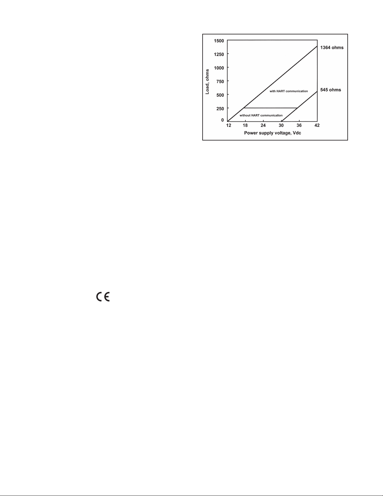
Power & Load Requirements: Supply voltage
at the transmitter terminals should be at least
12 Vdc. Power supply voltage should cover
the voltage drop on the cable plus the external
load resistor required for HART communications
(250 Ω minimum). Minimum power supply
voltage is 12 Vdc. Maximum power supply
voltage is 42.4 Vdc. The graph shows the
supply voltage required to maintain 12 Vdc
(upper line) and 30 Vdc (lower line) at the
transmitter terminals when the current is 22 mA.
Analog Output: Two-wire, 4-20 mA output with
superimposed HART
®3
digital signal. Fully
scalable over the operating range of the sensor.
Output accuracy: ±0.05 mA
FOUNDATION FIELDBUS —
Power & Load Requirements: A power supply
voltage of 9-32 Vdc at 13 mA is required.
Fieldbus Intrinsically Safe COncept/FISCO-
compliant versions of Model Xmt Foundation
Fieldbus transmitters are available.
Page 4
Page 4
GENERAL SPECIFICATIONS FOR Xmt-A
Input ranges: 0-330 nA, 0.3-4µA, 3.7-30 µA,
27-100 µA
Repeatability (input): ±0.1% of range
Linearity (input): ±0.3% of range
Temperature range: -10 to 100°C (-10 to 150°C for
steam sterilizable sensors)
Temperature accuracy using RTD: ±0.5°C between
0 and 50°C, ±1°C above 50°C
Temperature accuracy using 22k NTC: ±0.5°C
between 0 and 50°C, ±2°C above 50°C
Digital Communications:
HART: PV, SV, TV, and 4V assignable to measure-
ment (oxygen, ozone, chlorine, or monochloramine), temperature, pH, and sensor current.
Fieldbus: Four (4) AI blocks assignable to meas-
urement (oxygen, ozone, or chlorine), temperature, pH, and sensor current; execution time 75
msec. One PID block; execution time 150 msec.
Device type: 4086. Device revision: 1. Certified to
ITK 4.6.
HAZARDOUS LOCATION APPROVALS
Intrinsic Safety (with appropriate safety barrier):
Class I, II, III, Div. 1
Groups A-G
T4 Tamb = 50°C
Class I, II, III, Div. 1
Groups A-G
T4 Tamb = 50°C
1180 II 1 G
Baseefa04ATEX0213X
EEx ia IIC T4
Tamb = 0°C to 50°C
Non-Incendive:
Class I, Div. 2, Groups A-D
Dust Ignition Proof
Class II & III, Div. 1, Groups E-G
NEMA 4/4X Enclosure
Class I, Div. 2, Groups A-D
Dust Ignition Proof
Class II & III, Div. 1, Groups E-G
NEMA 4/4X Enclosure
T4 Tamb = 50°C
MODEL Xmt-A AMPEROMETRIC TRANSMITTER
FEATURES
The Model Xmt-A Transmitter with the appropriate
sensor measures dissolved oxygen (ppm and ppb
level), free chlorine, total chlorine, monochloramine,
and ozone in water and aqueous solutions. The transmitter is compatible with Rosemount Analytical 499A
amperometric sensors for oxygen, chlorine, monochloramine, and ozone; and with Hx438, Bx438, and
Gx448 steam-sterilizable oxygen sensors.
For free chlorine measurements, both automatic and
manual pH correction are available. pH correction is
necessary because amperometric free chlorine sensors respond only to hypochlorous acid, not free chlorine, which is the sum of hypochlorous acid and
hypochlorite ion. To measure free chlorine, most competing instruments require an acidified sample. Acid
lowers the pH and converts hypochlorite ion to
hypochlorous acid. The Model Xmt-A eliminates the
need for messy and expensive sample conditioning by
measuring the sample pH and using it to correct the
chlorine sensor signal. If the pH is relatively constant,
a fixed pH correction can be used, and the pH measurement is not necessary. If the pH is greater than 7.0
and fluctuates more than about 0.2 units, continuous
measurement of pH and automatic pH correction is
necessary. See Specifications section for recommended pH sensors. Corrections are valid to pH 9.5.
The transmitter fully compensates oxygen, ozone, free
chlorine, total chlorine, and monochloramine readings
for changes in membrane permeability caused by temperature changes.
For pH measurements — pH is available with free
chlorine only — the Xmt-A features automatic buffer
recognition and stabilization check. Buffer pH and
temperature data for commonly used buffers are
stored in the transmitter. Glass impedance diagnostics
warn the user of an aging or failed pH sensor.
ATEX
Page 5

MODEL Xmt-A AMPEROMETRIC TRANSMITTER
SPECIFICATIONS — OXYGEN
Measurement Range: 0-20 ppm (mg/L),
or equivalent partial pressure or % saturation
(limited by sensor)
Units: ppm, ppb, % saturation, partial pressure
(mmHg, inHg, atm, mbar, bar, kPa)
Resolution: 4 digits. Position of decimal point
depends on units selected
for partial pressure (x.xxx to xxxx)
for % saturation (fixed at xxx.x%)
for ppm (fixed at xx.xx ppm) =,
for ppb (fixed at xxx.x ppb, changes to 1.00 ppm
when ppb reading exceeds 999.9 ppb) =,xxxxppm
Temperature correction for membrane permeability:
automatic between 0 and 50°C (can be disabled)
Calibration: air calibration (user must enter baromet-
ric pressure) or calibration against a standard
instrument
SENSORS — OXYGEN:
Model 499A DO-54, 499A DO-54-VP for ppm level
Model 499A TrDO-54, 499A TrDO-54-VP for ppb level
Hx438, Bx438, and Gx448 steam-sterilizable oxygen
sensors
SPECIFICATIONS — FREE CHLORINE
Measurement Range: 0-20 ppm (mg/L) as Cl
2
(limited by sensor)
Resolution: 0.001 ppm (Autoranges at 0.999 to 1.00
and 9.99 to 10.0)
Temperature correction for membrane permeability:
automatic between 0 and 50°C (can be disabled)
pH Correction: Automatic between pH 6.0 and 9.5.
Manual pH correction is also available.
Calibration: against grab sample analyzed using
portable test kit.
SENSORS — FREE CHLORINE:
Model 499A CL-01-54, 499A CL-01-54-VP
SPECIFICATIONS — TOTAL CHLORINE
Measurement Range: 0-20 ppm (mg/L) as Cl
2
(limited by sensor)
Resolution: 0.001 ppm (Autoranges at 0.999 to 1.00
and 9.99 to 10.0)
Temperature correction for membrane permeability:
automatic between 5 and 35°C (can be disabled)
Calibration: against grab sample analyzed using
portable test kit.
SENSOR — TOTAL CHLORINE:
Model 499A CL-02-54 (must be used with SCS 921A)
SPECIFICATIONS — pH
Application: pH measurement available with free
chlorine only
Measurement Range: 0-14 pH
Resolution: 0.01 pH
Sensor Diagnostics: Glass impedance (for broken
or aging electrode) and reference offset.
Reference impedance (for fouled reference junction) is not available.
Repeatability: ±0.01 pH at 25°C
SENSORS — pH:
Use Model 399-09-62, 399-14, or 399VP-09.
SPECIFICATIONS — MONOCHLORAMINE
Measurement Range: 0-20 ppm (mg/L) as Cl
2
(limited by sensor)
Resolution: 0.001 ppm (Autoranges at 0.999 to 1.00
and 9.99 to 10.0)
Temperature correction for membrane permeability:
automatic between 5 and 35°C (can be disabled)
Calibration: against grab sample analyzed using
portable test kit.
SENSORS — MONOCHLORAMINE:
Model 499A CL-03-54, 499A CL-03-54-VP
SPECIFICATIONS — OZONE
Measurement Range: 0-10 ppm (mg/L) (limited by
sensor)
Units: ppm and ppb
Resolution:
for ppm: x.xxx to xxxx
for ppb: xxx.x to xxxx
Temperature correction for membrane permeability:
automatic between 5 and 35°C (can be disabled)
Calibration: against grab sample analyzed using
portable test kit.
SENSORS — OZONE:
Model 499A OZ-54, 499A OZ-54-VP
Page 5
Page 6

MODEL Xmt-P pH/ORP TRANSMITTER
FEATURES
The Model Xmt-P Transmitter with the appropriate sensor can be configured for either pH or ORP (oxidation
reduction potential) measurement of aqueous solutions. Housed in a NEMA 4X case, the Model Xmt can be located close to the sensor even in the harshest environments, including process, water or wastewater monitoring.
Advanced features include automatic 2-point buffer calibration routine, automatic recognition of Pt 100 or Pt 1000
RTD, and menu-selected internal preamplifier. Predictive sensor diagnostic capability is possible through the
impedance measurement of the pH glass membrane and reference electrode, fully supported by AMS. Solution
temperature calibration allows the instrument to calculate and display the pH at 25°C when the temperature coefficient of the measured liquid is provided.
FUNCTIONAL SPECIFICATIONS
pH Range: 0 to 14
ORP Range: -1400 to +1400mV
Calibrations/standardization: The automatic buffer
recognition uses stored buffer values and their temperature curves for the most common buffer standards available worldwide. The transmitter also
performs a stabilization check on the sensor in
each buffer.
A manual two-point calibration is made by immersing the sensor in two different buffer solutions and
entering the pH values. The microprocessor automatically calculates the slope which is used for selfdiagnostics. An error message will be displayed if
the pH sensor is faulty. This slope can be read on
the display and/or manually adjusted if desired.
An on-line one-point process standardization is
accomplished by entering the pH or ORP value of a
grab sample.
Preamplifier Location: A preamplifier must be used to
convert the high impedance pH electrode signal to a
low impedance signal for transmitter use. The integral preamplifier of the Model Xmt-P may be used
when the sensor to transmitter distance is less than
15 ft (4.5 m). Locate the preamplifier in the sensor
or junction box for longer distances.
Automatic Temperature Compensation: External 3-
wire Pt100 RTD or Pt1000 RTD located in the sensor, compensates the pH reading for temperature
fluctuations. Compensation covers the range -15 to
130°C (5 to 270°F). Manual temperature compensation is also selectable.
Accuracy: ±1 mV @ 25°C ± 0.01 pH
Repeatability: ±1 mV @ 25°C ± 0.01 pH
Diagnostics: The internal diagnostics can detect:
Calibration Error Sensor Failure
High Temperature Warning CPU Failure
Low Temperature Warning Input Warning
ROM Failure Glass Warning
Glass Failure Reference Warning
Reference Failure
Once one of the above is diagnosed, the display
will show a message describing the problem.
DIGITAL COMMUNICATIONS:
HART (pH): PV assigned to pH. SV, TV, and 4V
assignable to pH, temperature, mV, glass
impedance, reference impedance, or RTD
resistance.
HART (ORP): PV assigned to ORP. SV, TV, and
4V assignable to ORP, temperature, reference
impedance, or RTD resistance.
Fieldbus (pH): Four AI blocks assigned to pH,
temperature, reference impedance, and glass
impedance.
Fieldbus (ORP): Three AI blocks assigned to
ORP, temperature, and reference impedance.
Fieldbus (pH and ORP): Execution time 75 msec.
One PID block; execution time 150 msec.
Device type 4088. Device revision 1. Certified to
ITK 4.6.
HAZARDOUS LOCATION APPROVALS
Intrinsic Safety (with appropriate safety barrier):
Class I, II, III, Div. 1
Groups A-G
T4 Tamb = 50°C
Class I, II, III, Div. 1
Groups A-G
T4 Tamb = 50°C
1180 II 1 G
Baseefa04ATEX0213X
EEx ia IIC T4
Tamb = 0°C to 50°C
Non-Incendive:
Class I, Div. 2, Groups A-D
Dust Ignition Proof
Class II & III, Div. 1, Groups E-G
NEMA 4/4X Enclosure
Class I, Div. 2, Groups A-D
Dust Ignition Proof
Class II & III, Div. 1, Groups E-G
NEMA 4/4X Enclosure
T4 Tamb = 50°C
Page 6
ATEX
Page 7

Page 7
MODEL Xmt-P pH/ORP TRANSMITTER
SENSOR COMPATIBILITY CHART
pH/ORP SENSOR DIAGNOSTIC CAPABILITY
320HP-58 Glass only
328A Glass only
370 Glass only
371 Glass only
372 Glass only
381 pHE-31-41-52 Glass only
381+ Glass and Reference
385+ Glass and Reference
389-02-54 / 389VP-54 Glass only
396-54-62 / 396VP Glass only
396P-55 / 396PVP-55 Glass and Reference
396R / 396RVP-54 Glass and Reference
397-54-62 Glass only
398-54-62 / 398VP-54 Glass only
398R-54-62 / 398RVP-54 Glass only
399-09-62 / 399VP-09 / 399-14 Glass only
Hx338 Glass only
Hx348 Glass only
TF396 none
Page 8

FUNCTIONAL SPECIFICATIONS
Automatic Temperature Compensation:
3-wire Pt 100 or Pt 1000 RTD
Conductivity: 0 to 200°C (32 to 392°F)
Resistivity: 0 to 100°C (32 to 212°F)
Low Conductivity: 0 to 100°C (32 to 212°F)
Diagnostics: The internal diagnostics can detect:
Calibration Error ROM Failure
Temperature Slope Error Zero Error
High Temperature Warning CPU Failure
Low Temperature Warning Input Warning
Once one of the above is diagnosed, the Xmt-C will display
a message describing the problem.
Digital Communications:
HART: PV, SV, and TV assignable to measurement (con-
ductivity, resistivity, or concentration), temperature, and
raw conductivity. Raw conductivity is measured conductivity before temperature correction.
Fieldbus: Three AI blocks assignable to measurement (con-
ductivity, resistivity, or concentration), temperature, and
raw conductivity. Raw conductivity is measured conductivity before temperature correction. Execution time 75 msec.
One PID block; execution time 150 msec. Device type:
4087. Device revision: 1. Certified to ITK 4.6.
TRANSMITTER SPECIFICATIONS @ 25°C
Measured Range: 0-20,000 μS/cm
Accuracy: ± 0.7% of reading and ± 0.002 µS/cm
Repeatability: ± 0.25% of reading
Temperature Accuracy: ± 0.2°C between 0 and 50°C; ±
0.5°C above 50°C (excludes inaccuracies in sensor)
Temperature Compensation: Slope 0-5%/°C, ultra-pure
water, cation conductivity, or raw (uncompensated) conductivity.
Compatible RTD: 100Ω or 1000Ω with automatic recognition
Ambient Temperature Coefficient:
± 0.05% of reading/°C
Maximum Cable Length: 200 ft (61 m)
LOOP SPECIFICATIONS
Accuracy: under controlled laboratory conditions at 25°C
(77°F) with perfectly calibrated ENDURANCE sensor of
appropriate cell constant:
Calibration: Calibrate against previously calibrated stan-
dard sensor and analyzer, or calibrate against solution of
known conductivity.
SENSOR SELECTION GUIDELINES
Note: The conductivity values shown in the above chart are for
UNCOMPENSATED (or RAW) conductivity at 25°C.
Maximum range values will vary due to temperature compensation selection, process temperature, and other process
conditions.
RECOMMENDED SENSORS:
Model 140 Retractable Conductivity
Model 141 Insertion High Conductivity
Model 142 Insertion Low Conductivity
Model 150 Insertion/Submersion Conductivity
Model 400/VP Screw-In Low Conductivity
Model 401 Screw-In High Conductivity
Model 402/VP Retractable Conductivity
Model 403/VP Sanitary Conductivity
Model 404 Low Flow Conductivity
HAZARDOUS LOCATION APPROVALS
Intrinsic Safety(with appropriate safety barrier):
Class I, II, III, Div. 1
Groups A-G
T4 Tamb = 50°C
Class I, II, III, Div. 1
Groups A-G
T4 Tamb = 50°C
ATEX 1180
II 1 G
Baseefa04ATEX0214X
EEx ia IIC T4
Tamb = 0°C to 50°C
Non-Incendive:
Class I, Div. 2, Groups A-D
Dust Ignition Proof
Class II & III, Div. 1, Groups E-G
NEMA 4/4X Enclosure
Class I, Div. 2, Groups A-D
Dust Ignition Proof
Class II & III, Div. 1, Groups E-G
NEMA 4/4X Enclosure
T4 Tamb = 50°C
Page 8
MODEL Xmt-C CONTACTING CONDUCTIVITY TRANSMITTER
FEATURES
The Model Xmt-C measures conductivity, resistivity, total dissolved solids, or % concentration. It can also be configured, using
the "Custom Curve" feature, to measure ppm, %, or a no unit variable according to a programmable conductivity vs. variable
curve. The transmitter automatically recognizes the type of RTD (Pt100 or Pt1000) being used. Measurements are automatically corrected for the resistance of the sensor cable to improve accuracy of high conductivity readings. The Xmt-C provides
several temperature compensation algorithms: linear slope, ultra-pure water (neutral salt), or cation conductivity. Alternatively,
temperature compensation feature can be turned off to provide display of raw conductivity.
Cell Constant Range Loop accuracy
0.01/cm up to 50 μS/cm ±0.7% of reading
±0.002 μS/cm
0.1/cm 0.4 to 50 μS/cm ±0.7% of reading
50 to 200 μS/cm ±2% of reading
1.0/cm 4 to 5000 μS/cm ±0.7% of reading
5000 to 20,000 μS/cm ±2% of reading
Cell Constant Suggested Conductivity Range
0.01/cm up to 50 μS/cm
0.1/cm 0.4 to 500 μS/cm
1.0/cm 4 to 20,000 μS/cm
Page 9

Page 9
MODEL Xmt-T TOROIDAL CONDUCTIVITY TRANSMITTER
FEATURES
The Model Xmt-T measures conductivity or % concentration in the harshest environments. Transmitter can also be configured,
using the "Custom Curve" feature, to measure ppm, %, or a no unit variable according to a programmable conductivity vs.
variable curve. The transmitter recognizes the type of RTD (Pt100 or Pt1000) being used. Measurements are automatically
corrected for the resistance of the sensor cable to improve accuracy of high conductivity readings. The Xmt-T is preprogrammed with several concentration curves: 0-12% NaOH, 0-15% HCl, 0-20% NaCl, and 0-25% and 96-99.7% H
2SO4
. Tem-
perature compensation choices are linear slope correction or none (to provide display of raw conductivity).
FUNCTIONAL SPECIFICATIONS
Automatic Temperature Compensation:
3-wire Pt 100 RTD or Pt 1000 RTD
Conductivity: 0 to 200°C (32 to 392°F)
% Concentration: 0 to 100°C (32 to 212°F)
Diagnostics: The internal diagnostics can detect:
Calibration Error ROM Failure
Temperature Slope Error Zero Error
High Temperature Warning CPU Failure
Low Temperature Warning Input Warning
Once one of the above is diagnosed, the LCD will display a
message describing the problem.
Digital Communications:
HART: PV, SV, and TV assignable to measurement (con-
ductivity, resistivity, or concentration), temperature, and
raw conductivity. Raw conductivity is measured conductivity before temperature correction.
Fieldbus: Three AI blocks assignable to measurement
(conductivity, resistivity, or concentration), temperature,
and raw conductivity. Raw conductivity is measured
conductivity before temperature correction. Execution
time 75 msec. One PID block; execution time 150
msec. Device type: 4087. Device revision: 1. Certified
to ITK 4.6.
TRANSMITTER SPECIFICATIONS @ 25°C
Measured Range: 50 to 2,000,000 µS/cm (see chart)
Repeatability: ± 0.25% of reading
Temperature Accuracy:
± 0.2°C between 0 and 50°C
± 0.5°C above 50°C
(excludes inaccuracies in sensor)
Temperature Slope Adjustment: 0-5%/° C
% Concentration Ranges:
Sodium Hydroxide: 0 to 12%
Hydrochloric Acid: 0 to 15%
Sulfuric Acid: 0 to 25% and 96.0 to 99.7%
Sodium Chloride: 0 to 20%
Ambient Temperature Coefficient:
± 0.1% of reading ±2µS/cm per °C
Maximum Cable Length: 100 ft (30 m)
LOOP SPECIFICATIONS
Loop Accuracy: With a standard Model 228 or 225 sensor
with 20' cable, following a single point calibration, laboratory accuracy at 25°C can be as good as ±2% of reading
and ±50 µS/cm.
For optimum performance, standardize the sensor in the
process at the conductivity and temperature of interest.
Results under real process conditions, at different tem-
peratures, or using other sensors may differ from above.
Calibration: Calibrate against previously calibrated standard
sensor and analyzer, or calibrate against solution of known
conductivity.
RECOMMENDED SENSORS:
Model 222 Flow-Through
Model 225 Clean-In-Place (CIP)
Model 226 Submersion/Insertion
Model 228 Submersion/Insertion/Retractable
Model 242 Flow-Through
Model 245 Sanitary Flow-Through
Model 247 Submersion/Flow-Tee
HAZARDOUS LOCATION APPROVALS
Intrinsic Safety (with appropriate safety barrier):
Class I, II, III, Div. 1
Groups A-G
T4 Tamb = 50°C
Class I, II, III, Div. 1
Groups A-G
T4 Tamb = 50°C
ATEX 1180
II 1 G
Baseefa04ATEX0215X
EEx ia IIC T4
Tamb = 0°C to 50°C
Non-Incendive:
Class I, Div. 2, Groups A-D
Dust Ignition Proof
Class II & III, Div. 1, Groups E-G
NEMA 4/4X Enclosure
Class I, Div. 2, Groups A-D
Dust Ignition Proof
Class II & III, Div. 1, Groups E-G
NEMA 4/4X Enclosure
T4 Tamb = 50°C
Values shown are for 25°C conductivity with a temperature slope of 2% per degree C. The maximum range value
will be lower for solutions with a higher temperature slope. Minimum conductivity depends on sensor.
RECOMMENDED RANGES FOR TOROIDAL SENSORS
Conductivity Sensor Model 226 228 225 222 (1in.) 222 (2 in.) 242 245 247
Nominal Cell Constant 1.0 3.0 3.0 6.0 4.0 * * 3.5
Minimum Conductivity (μS/cm) 50 200 200 500 500 100* 100* 500
Maximum Conductivity (μS/cm) 1,000,000 2,000,000 2,000,000 2,000,000 2,000,000 2,000,000* 2,000,000 2,000,000
* Model 242 values depend on sensor configuration and wiring.
Page 10

Page 10
TYPICAL MAIN SCREEN DISPLAYS:
Xmt-P
pH
to show impedance:
Xmt-C
Conductivity
Xmt-T:
Percent Concentration
Xmt-A
Free chlorine with pH correction
Easy-to-use menus guide you through every step of
the programming. Here’s how easy it is to calibrate a
chlorine sensor:
12.34 pH
26.3°C 16.78mA
12.34 pH 26.3°C
G:1234M^ R:123k^
12.34 µS/cm
26.3°C 16.78mA
12.34 %
26.3°C 16.78mA
1.234 ppm
26.3°C 16.78mA
12.34 PPM
26.3°c 16.78pH
Enter Security
Code: 000
Calibrate Hold
Program Display
Cal? pH
Chlorine Temp
Cal?
InProcess Zero
Wait for
stable reading.
Stable? 10.00ppm
Press enter.
Take sample;
Press enter.
Live 10.00ppm
Cal 10.00ppm
Cal in progress.
Please wait.
Main display screen
shows for 2 sec
As soon as you press
ENTER on this screen,
the transmitter stores the
sensor current, temperature, and pH (if appropriate) and uses that current
in the calibration.
Change this reading
to match test results.
Transmitter completes
the calibration.
MENU key
ENTER key
ENTER key
ENTER key
ENTER key
ENTER key
ENTER key
ENTER key
Page 11

Page 11
ASSET MANAGEMENT SOLUTIONS (AMS) (FIGURES 2, 3, & 4)
Rosemount Analytical AMS windows provide access to all transmitter measurement and configuration variables. The
user can read raw data, final data, and program settings and can reconfigure the transmitter from anywhere in the plant.
Figures 2 and 3 show two of the many configuration and measurement screens available using HART AMS. Figure 4
shows a configuration screen available through AMS Inside using FOUNDATION fieldbus.
FIGURE 2. AMS CONFIGURATION SCREEN USING HART
FOUNDATION FIELDBUS (FIGURE 1)
Figure 1 shows a Xmt-A-FF being used to measure and control pH and chlorine levels in drinking water. The figure also
shows three ways in which fieldbus communication can be used to read process variables and configure the transmitter.
FIGURE 1. CONFIGURING MODEL Xmt-A TRANSMITTER WITH FOUNDATION FIELDBUS
Page 12

Page 12
FIGURE 3. AMS MEASUREMENT SCREEN USING HART
FIGURE 4. AMS INSIDE CONFIGURATION SCREEN USING FOUNDATION FIELDBUS
Page 13

Page 13
FIGURE 5. PANEL MOUNTING
Access to the wiring terminals is through the rear cover. Four screws hold the cover in place.
MILLIMETER
INCH
Page 14

Page 14
FIGURE 6. SURFACE MOUNTING
The front panel is hinged at the bottom. The panel swings down for access to the wiring terminals.
MILLIMETER
INCH
Page 15

Page 15
FIGURE 7. PIPE MOUNTING
The front panel is hinged at the bottom. The panel swings down for access to the wiring terminals.
MILLIMETER
INCH
Page 16

ORDERING INFORMATION
The Solu Comp Model Xmt Two-Wire Transmitter is intended for the determination of pH/ORP, conductivity
(both contacting and toroidal), and for measurements using membrane-covered amperometric sensors (oxygen,
ozone, free and total chlorine, and monochloramine). For free chlorine measurements, which often require continuous pH correction, a second input for a pH sensor is standard.
ACCESSORIES
MODEL/PN DESCRIPTION
515 DC loop power supply (see product data sheet 71-515)
230A Alarm module (see product data sheet 71-230A)
23820-00 2-in. pipe mounting kit
9240048-00 Stainless steel tag, specify marking
23554-00 Gland fittings PG 13.5, 5 per package
Credit Cards for U.S. Purchases Only.
The right people,
the right answers,
right now.
ON-LINE ORDERING NOW AVAILABLE ON OUR WEB SITE
http://www.raihome.com
Specifications subject to change without notice.
Emerson Process Management
Liquid Division
2400 Barranca Parkway
Irvine, CA 92606 USA
Tel: (949) 757-8500
Fax: (949) 474-7250
http://www.raihome.com
© Rosemount Analytical Inc. 2008
CODE REQUIRED SELECTION
HT Analog 4-20 mA output with superimposed HART digital signal
FF Foundation fieldbus digital output
FI Foundation fieldbus digital output with FISCO
CODE REQUIRED SELECTION
10 Panel mounting enclosure
11 Pipe/Surface mounting enclosure (pipe mounting requires accessory kit PN 23820-00)
CODE AGENCY APPROVALS
60 No approval
67 FM approved intrinsically safe and non-incendive (when used with appropriate sensor and safety barrier)
69 CSA approved intrinsically safe and non-incendive (when used with appropriate sensor and safety barrier)
73 ATEX approved intrinsically safe (when used with appropriate sensor and safety barrier)
CODE REQUIRED SELECTION
P pH/ORP
C Contacting conductivity
T Toroidal conductivity
A Amperomentric (oxygen, ozone, and chlorine)
MODEL
Xmt SMART TWO-WIRE MICROPROCESSOR TRANSMITTER
Xmt-P-HT-10-67 EXAMPLE
 Loading...