

Page 1
HAGAN POWER
POSITIONER
TORQUE TYPE
6x 10 INCH
Instruction Bulletin IB-102-207 Rev. 2
Supercedes II-102.207 dated January, 1985
FISHER-ROSEMOUIIT”ManagingThe Process Better
Page 2

Page 3
ROSEMOUNT WARRANTY
Rosemount warrants that the equipment manufactured and sold by it will, upon shipment, be free
of defects in workmanship or material. Should any failure to conform to this warranty become apparent
daring a period of one year after date of shipment, Rosemount shall, upon prompt written notice from the
purchaser, correct such nonconformity by repair or replacement, F.O.B. factory of the defective part or parts.
Correction in the manner provided above shall constitute a fulfillment of all liabilities of Rosemount with
respect to the quality of the equipment.
THE FOREGOING WARRANTY IS EXCLUSIVE AND JN LIEU OF ALL OTHER WARRANTIES
OF QUALITY WHETHER WRIT-l-RN, ORAL, OR IMPLIED (INCLUDING ANY WARRANTY OF
MERCHANTABILITY OF FITNESS FOR PURPOSE).
The remedy(ies) provided above shall be purchaser’s sole remedy(ies) for any failure of Rosemount to
comply with the warranty provisions, whether claims by the purchaser are baaed in contract or in tort
(including negligence).
Rosemount does not warrant equipment against deterioration due to environment. Factors such as corrosive
gases and solid particulates can be detrimental and can create the need for repair or replacement as part of
normal wear and tear daring the warranty period.
Equipment supplied by Rosemount Analytical Inc. but not manufactured by it, will be subject to the same
warranty as is extended to Rosemount by the original manufacturer.
Page 4
PURPOSE
The purpose of this manual is to provide a comprehensive understanding of the Hagan 6 x 10
Power Positioner, components, functions, installation, and maintenance.
This manual is designed to provide information about the Hagan 6 x 10 Power Positioner. We
recommend that you thoroughly familiarize yourself with the Description and Installation section before
installing your power positioner.
The overview presents the basic principles of the power positioner along with the it’s performance
characteristics and components. The remaining sections contain detail procedures and information necessary
for installation and servicing of the power positioner.
Before contacting Rosemount concerning any questions, fast consult this manual. It describes most
situations encountered in your equipment’s operation and details necessary action.
DEFINITIONS
The following defmitions apply to WARNINGS, CAUTIONS, and NOTES found throughout this
publication.
WARNING
Highlights an operation or maintenance procedure, practice, condition, statement, etc., if not strictly
observed, could result in injury, death, or long-term health hazards of personnel.
CAUTION
Highlights an operation or maintenance procedure, practice, condition, statement, etc., if not strictly
observed, could result in damage to or destruction of equipment, or loss of effectiveness.
NOTE
Highlights an essential operating procedure, condition, or statement.
NOTE TO USERS
The P- number in the lower right comer of the illustrations in this publication are manual
illustration numbers. They are not part numbers, and are not related to the illustration in any technical
manner.
IB-m2-*07
it
Page 5
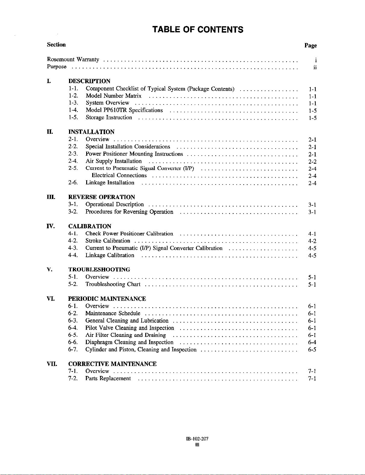
TABLE OF CONTENTS
SWtiOU
RosemountWarranty . . . . ..__................_______.......... i
Purpose . . ..___...................................___...__
I.
II.
III.
DESCRIPTION
l-l. Component Checklist of Typical System (Package Contents)
1-2. Model Number Matrix
l-3. System Overview
l-4. Model PP61OTR Specifications
l-5. storage Instruction
INSTALLATION
2-1. Overview
2-2. Special Installation Considerations
2-3. Power Positioner Mounting Instructions
2-4. Air Supply Installation
2-5. Current to Pneumatic Signal Converter (I/P)
Electrical Connections
2-6. Linkage Installation ..__.
REVERSE OPERATION
3-l. Operational Description
3-2. Procedures for Reversing Operation
. . . . . . . .
..... 2-1
...... 2-1
...... 2-1
...... 2-2
...... 2-4
...... 2-4
...... 2-4
Page
1-l
l-l
l-1
l-5
l-5
3-1
3-1
ii
IV.
V.
VI.
VII.
CALIBRATION
4-1. Check Power Positioner Calibration
4-2. Stroke Calibration
4-3. Current to Pneumatic (I/P) Signal Converter Calibration
4-4. Linkage Calibration
TROUBLESHOOTING
5-l. Overview
5-2. Troubleshooting Chart
PERIODIC MAINTENANCE
6-l. Overview
6-2. Maintenance Schedule
6-3. General Cleaning and Lubrication
6-4. Pilot Valve Cleaning and Inspection
6-5. Air Filter Cleaning and Draining
6-6. Diaphragm Cleaning and Inspection
6-7. Cylinder and Piston, Cleaning and Inspection
CORRECTIVE MAINTENANCE
7-1. Overview
7.2. Parts Replacement
...... 4-l
...... 4-2
...... 4-5
...... 4-5
......
......
...... 6-1
......
...... 6-l
...... 6-l
...... 6-l
...... 6-4
...... 6-5
......
......
5-l
5-l
6-1
7-l
7-l
Page 6
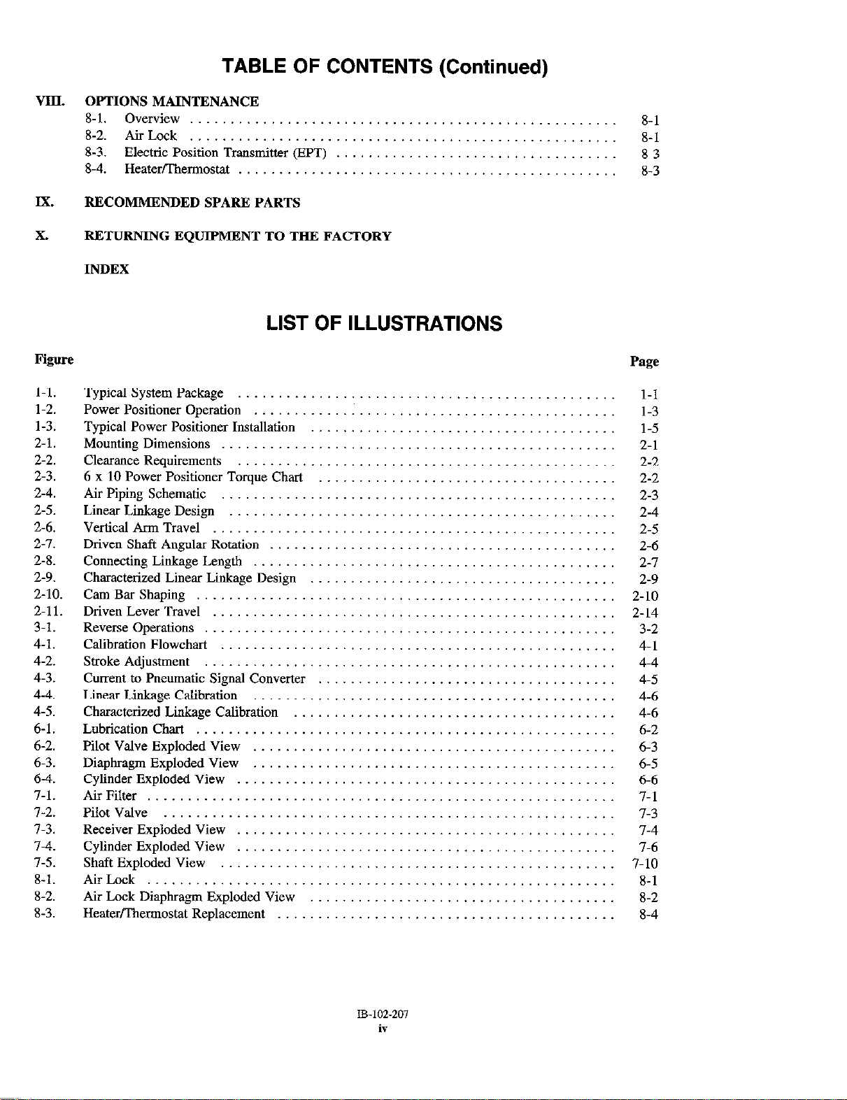
TABLE OF CONTENTS (Continued)
VIII. OPTIONS MAINTENANCE
8-l. Overview _........_...___..........__._...__.__.,,,,__
8-2. AirLock _.____.._........_...._..___..,..._.___....__,,,..,._ 8-l
8-3. Electric Position Transmitter @PT)
8-4. Heatwllwmostat
Ix. RECOMMENDED SPARE PARTS
8-l
8-3
8.3
X.
Figure
l-l.
l-2.
1-3.
2-l.
2-2.
2-3.
2.4.
2-5.
2-6.
2-l.
2-8.
2-9.
2-10.
2-11.
3-1.
4-1.
4-2.
4-3.
4-4.
4-5.
6-l.
6-2.
6-3.
6-4.
7-1.
l-2.
7-3.
l-4.
l-5.
8-l.
8-2.
8-3.
RETURNING EQUIPMENT TO THR FACTORY
INDEX
LIST OF ILLUSTRATIONS
Typical System Package
Power Positioner Operation
Typical Power Positioner Installation
Mounting Dimensions
Cleamnce Requirements
6
x 10 Power Positioner Torque Chart
Air Piping Schematic
Linear Linkage Design
Vertical Arm Travel
Driven Shaft Angular Rotation
Connecting Linkage. Length
Characterized Linear Linkage Design
Cam Bar Shaping
Driven Lever Travel
Reverse Operations
Calibration Flowchart
Stroke Adjustment
Current to Pneumatic Signal Converter
Linear Linkage Calibration
Characterized Linkage Calibration
Lubrication Chat
Pilot Valve Exploded View
Diaphragm Exploded View
Cylinder Exploded View
Air Filter
Pilot Valve
Receiver Exploded View
Cylinder Exploded View
Shaft Exploded View
Air Lock
Air Lock Diaphragm Exploded View
Heaterfllwmostat Replacement
Page
l-l
1-3
l-5
2-l
2-2
2-2
2-3
2-4
2-s
2-6
2-l
2-9
2-10
2-14
3-2
4-l
4-4
4-5
4-6
4-6
6-2
6-3
6-5
6-b
7-l
l-3
l-4
7-6
7-10
8-1
8-2
8-4
Page 7
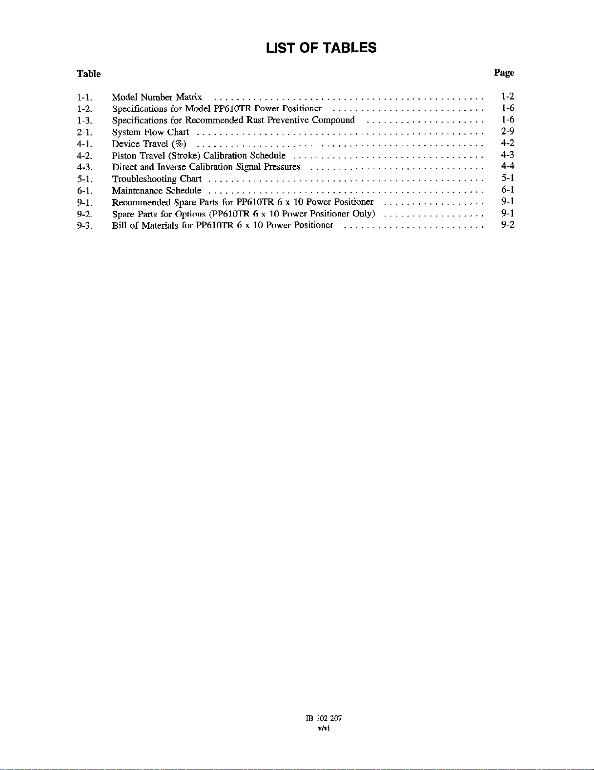
LIST OF TABLES
Table
l-1. Model Number Matrix
1-2. Specifications for Model PP61OTR Power Positioner ....................
1-3. Specifications for Recommended Rust Preventive Compound ..............
2-1.
4-1. Device Travel (%)
4-2. Piston Travel (Stroke) Calibration Schedule ...........................
4-3.
5-l.
6-l. Maintenance Schedule ..........................................
9-1.
9-2. Spare Parts for Options (PP61OTR 6 x 10 Power Positioner Only)
9-3.
SystemFlowChart
Direct and Inverse Calibration Signal Pressures ........................
Troubleshooting Chart ..........................................
Recommended Spare Parts for PP61OTR 6 x 10 Power Positioner ...........
Bill of Materials for PP61OTR 6 x 10 Power Positioner ..................
.........................................
............................................
............................................
...........
Page
l-2
1-6
1-6
2-9
4-2
4-3
4-4
5-l
6-1
9-1
9-l
9-2
Page 8

Page 9
SECTION I. DESCRIPTION
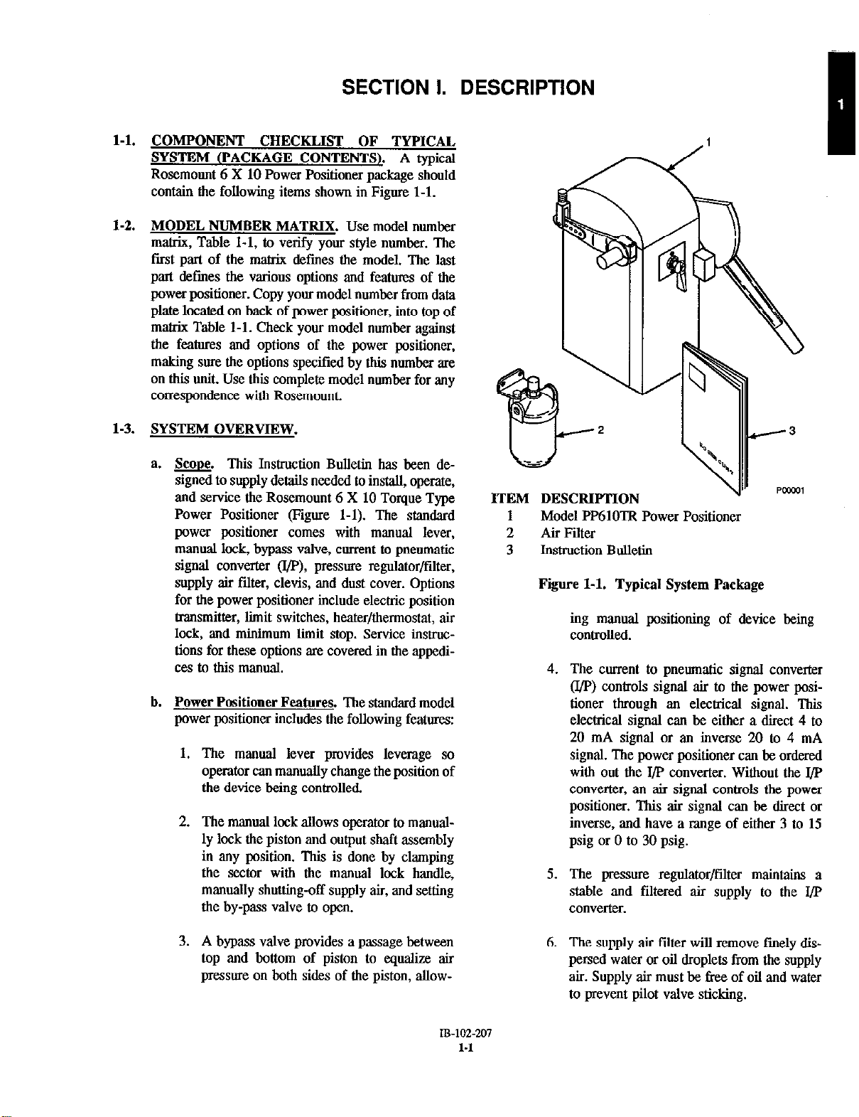
l-l.
COMPONENT CHECKLIST OF TYPICAL
SYSTEM (PACKAGE CONTENTS~. A typical
Rosemount 6 X 10 Power Positioner oackaae should
contain the following items shown in-Figure l-l.
1-2.
MODEL NUMBER MATRIX. Use model number
matrix, Table l-l, to verify your style number. The
first part of the matrix dcfmes the model. The last
part defmes the various options and feataxes of the
power positioner. Copy your model number from data
plate located on back of power positioner, into top of
matrix Table l-l. Check your model number against
the features and options of the p0we.r positioner,
making sure the options specified by this number are
on this unit. Use this complete model number for any
comespondcnce with Rosemount.
1-3.
SYSTEM OVERVIEW.
a.
w. This Instruction Bulletin has been de-
signed to supply details needed to install, operate,
and service the Rosemount 6 X 10 Torque Type
Power Positioner (Figure l-l). The standard
power positioner comes with manual lever,
manual lock, bypass valve, current to pneumatic
signal converter o/p), pressure rcgulator/tilter,
supply air filter, clevis, and dust cover. Options
for the power positioner include electric position
tmnsmitter, limit switches, heater/thermostat, air
lock, and minimum liiit stop. Service instmc-
tions for these options are covered in the appedices to this manual.
b.
Power Positioner Features. The standard model
power positioner includes the following features:
1.
The manual lever provides leverage so
operator can manually change the position of
the device being contilled.
2.
The manual lock allows operator to manually lock the piston and output shaft assembly
in any position. This is done by clamping
the sector with the manual lock handle,
manually shutting-off supply air, and setting
the by-pass valve to open.
ITEM DESCRIPTION
1 Model PP61OTR Power Positioner
2 Air Filter
3 Instruction Bulletin
Fire l-l. Typical System Package
ing manual positioning of device being
controlled.
4.
The current to pneumatic signal converter
(UP) controls signal air to the power posi-
tioner through an electrical signal. Thii
electrical signal can be either a direct 4 to
20 mA signal or an inverse. 20 to 4 mA
signal. The power positioner can be ordered
with out the I/P converter. Without the J/P
converter, an air signal controls the power
positioner. This air signal can be direct or
inverse, and have a range of either 3 to 15
psig or 0 to 30 psig.
5.
The pressure regulator/filter maintains a
stable and filtered air supply to the l/P
converter.
3.
A bypass valve provides a passage between
top and bottom of piston to cqualii air
pressure on both sides of the piston, allow-
IB-102-207
l-1
6.
The supply air filter will remove finely dis-
persed water or oil droplets from the supply
air. Supply air mast be free of oil and water
to prevent pilot valve sticking.
Page 10
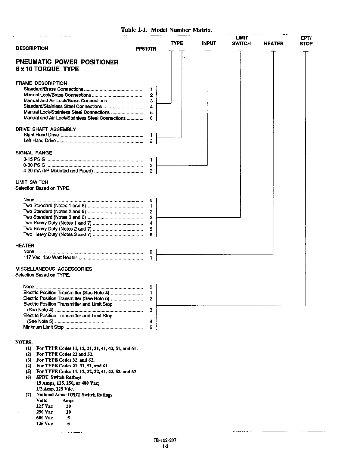
Table l-l. Model Number Matrix.
DESCRIPTION
PNEUMATIC POWER POSITIONER
6 x 10 TORQUE TYPE
FRAME DESCRlPTlON
Standard/Brass Connections ___..............................,............
Lodamss C0”“ecti0”s 2
Manual
Manual and Air Lc&‘Brass Connections ____.__............_.......
Sta”da”vstai”lsss stwl Co”“ecocns
Manual Lockistai”less steel Co”mtio”s
Manual and Air Lo&Stainless Steel Connections _________....
PP610TR
1
3
4
5
6
TYPE INPUT
!
UMIT
HEATER
I
EPT/
STOP
DRIVE SHAFT ASSEMBLY
Right Hand
Left Hand Drive . ..______...............................................
SIGNAL RANGE
515PSlG
O-30 PSIG ..__.___________...............,,,,,...................................
4-20 mA (I/P Mounted and Piped) .._.___...................
LIMIT SWITCH
Selection Based on TYPE
None ...................................................................................
Two Standard (Notes 1 and 6)
Two Standard (Notea 2 and 6) ...........................................
Two Standard (Notes 3 and 6) ...........................................
Two Heavy Duty (Notes 1 and 7) .......................................
Two Heavy Duty (Notes 2 aid 7) .......................................
Two Heavy Duty (Notes 3 and 7) .......................................
HEATER
None ._.______..,.,...._................................,..,,,.......................... 0
117Vac. 150WattHeater ._...__..___.........................,.,,,,,,,,,.. 1
MISCELLANEOUS ACCESSORIES
S&&o” Based on TYPE.
None ...................................................................................
El&ic Pmition Transmitter (See Note 4) .........................
Electric Position Transmitter fSee Note 51
Elecb’ic Position Transmitter Ad Ltmit Stop
(See
Electric Position Transmitter and Limit Stop
(See Note 5) _____._._................................,.,........................
Minimum Limit Stop .._........................................
Drive . . . . . . . . . . . . . . . . . . . . . . . . . . . . . . . . . . 1
. . . . . . . . . . . . . . . . . . . . . . . . . . . . . . . . . 1
........................................... 1
.........................
Note 4) 3
2
t--
2
3
0
2
3
4
5
6
0
1
2
4
5
NOTES:
(1)
For
(2) For TYF’E Codes 22 and 52.
TYPE Codes 11,X?, Zl, 3,,41,42,51, and 61.
(3) For TYPE Codes 32 and 62.
(4) For TYPE Cades 2l,3l, 51, and 61.
Q For TYPE Codes 11,12,22,32,41,42,52,
(6) SPDT Switch Ratings
15 *raps, 125,250, or 480 vat;
l/2 Amp, 125 Vdc.
(7) National Acme DPDT Switch Rat,,,@
VOlf.9
bps
125vae 20
25ovac 10
600 Vat 5
U5Vdc 5
and 62.
IB-1u2-207
1.2
Page 11
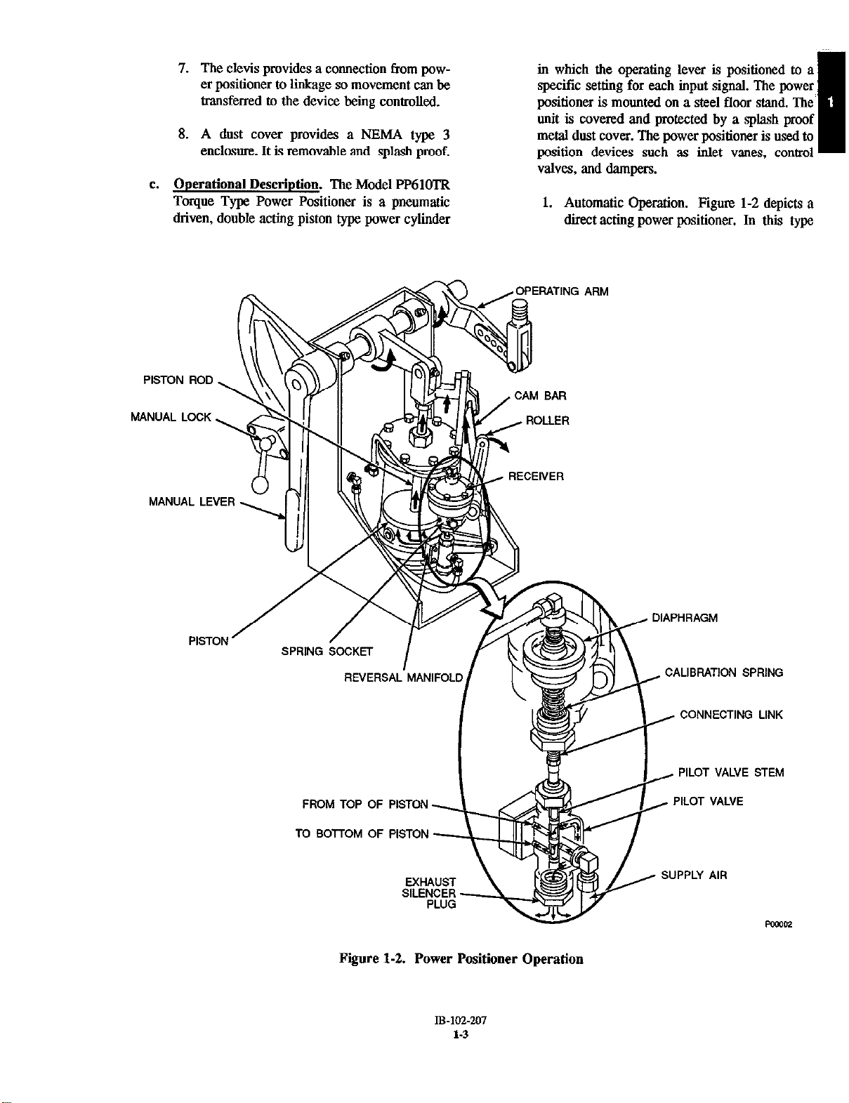
7.
The clevis provides a connection from powcr positioner to liige so movement can be
transferred to the device being controlled.
8.
A dust cover provides a NEMA type 3
enclosure. It is removable and splash proof.
e.
Operational Description. The Model PP61OTR
Torque Type Power Positioner is a pneumatic
driven, double acting piston type power cylinder
in which the operating lever is positioned to a
specific setting for each input signal. The power
positioner is mounted on a steel floor stand. The
unit is covered and protected by a splash proof
metal dust cover. The power positioner is used to
position devices such as inlet vanes, control
valves, and dampers.
1. Automatic Operation. Figure 1-2 depicts a
direct acting power positioner. In thii type
I
PISTON ROD
MANUAL LOCK,
MANUAL LEVER .-
PISTON ’
;1
/
I
/OPERATING ARM
DIAPHRAGM
CALIBRATION SPRING
FROM TOP
TO 801 OF
OF
Fiiure 1-2. Power Positioner Operation
CONNECTING LINK
PILOT VALVE STEM
PILOT VALVE
IB-162-207
t-3
Page 12
of positioner, a” increase in signal air pressure to the receiver causes the diaphragm to
overcome the tension of the calibration
spring moving the diaphragm downwards.
The downward motion is transmitted to the
pilot valve through a connecti”g link. Thii
positions the pilot valve stem to send supply
air below the piston forcing the piston,
piston rod, and operating arm upwards. Air
from above the piston is exhausted through
the pilot valves exhaust silencer plug.
The upward movement of the piston rod
raises the cam bar. This ca”ses the roller,
riding on the cam bar, to lift the spring
socket increasing pressure on the calibration
spring. The increased pressure on the calibration spring retwns the diaphragm to its
neutral position, closing the pilot valve air
ports. Without additional air, piston movcment is stopped.
As signal air decreases the calibration spring
pressure moves the diaphragm up. The
upward movement of the diaphragm moves
the pilot valve stem up directing air above
the piston. This forces the piston, piston rod,
and operating lever downward. The downward movement of the piston rod, working
through the cam bar and roller, lowers the
calibration spring socket and reduces pressure. on the calibration spring. This
decreased pressure on the calibration spring
returns the receiver’s diaphragm to a neutral
position closing the pilot valve air ports.
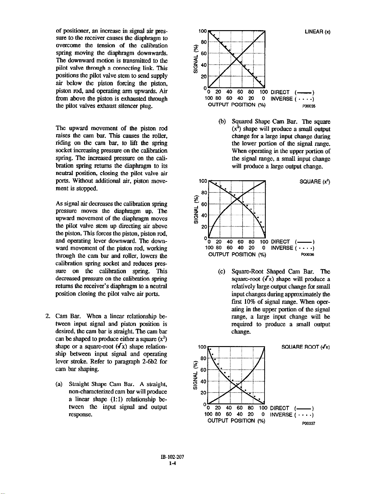
2.
Cam Bar. When a linear relationship between input signal and piston position is
desired, the cam bar is straight. The cam bar
can be shaped to produce either a square (9)
shape or a square-root (rx) shape relationship between input signal and operating
lever stroke. Refer to paragmph 2-6b2 for
cam bar shaping.
‘0 20 40 60
loo 80 60 40 20 0
OUTPUT POSITION (%)
80 100
DIRECT (-
INVERSE ( . . . .
Squared Shape Cam Bar. The square
(x2) shape will produce a small output
change for a large input change during
the lower portion of the signal range.
When operating in the upper portion of
the signal range, a small input change
will produce a huge output change.
100 80 60 40 20 0
OUTPUT POSITION (%)
DIRECT (-
INVERSE ( . . . .I
(c) Square-Root Shaped Cam Bar. The
square-root (fx) shape will produce a
relatively large output change for small
input changes during approximately the
fast 10% of signal range. When opersting in the upper portion of the signal
range, a large input change will be
rqdred to produce a small output
change.
SQUARE ROOl
LINEAR(x)
Pccnl5
SQUARE (9)
PM036
(a) Straight Shape Cam Bar. A straight,
non-characterized cam bar will produce
a linear shape (1:l) relationship between the input signal and output
02pO”S~.
IB-ICC-207
l-4
‘0 20 40 60
100 80 60
OUTPUT POSITION (%)
80 100
40 20 0
DIRECT (INVERSE ( . . .;
Km37
Page 13
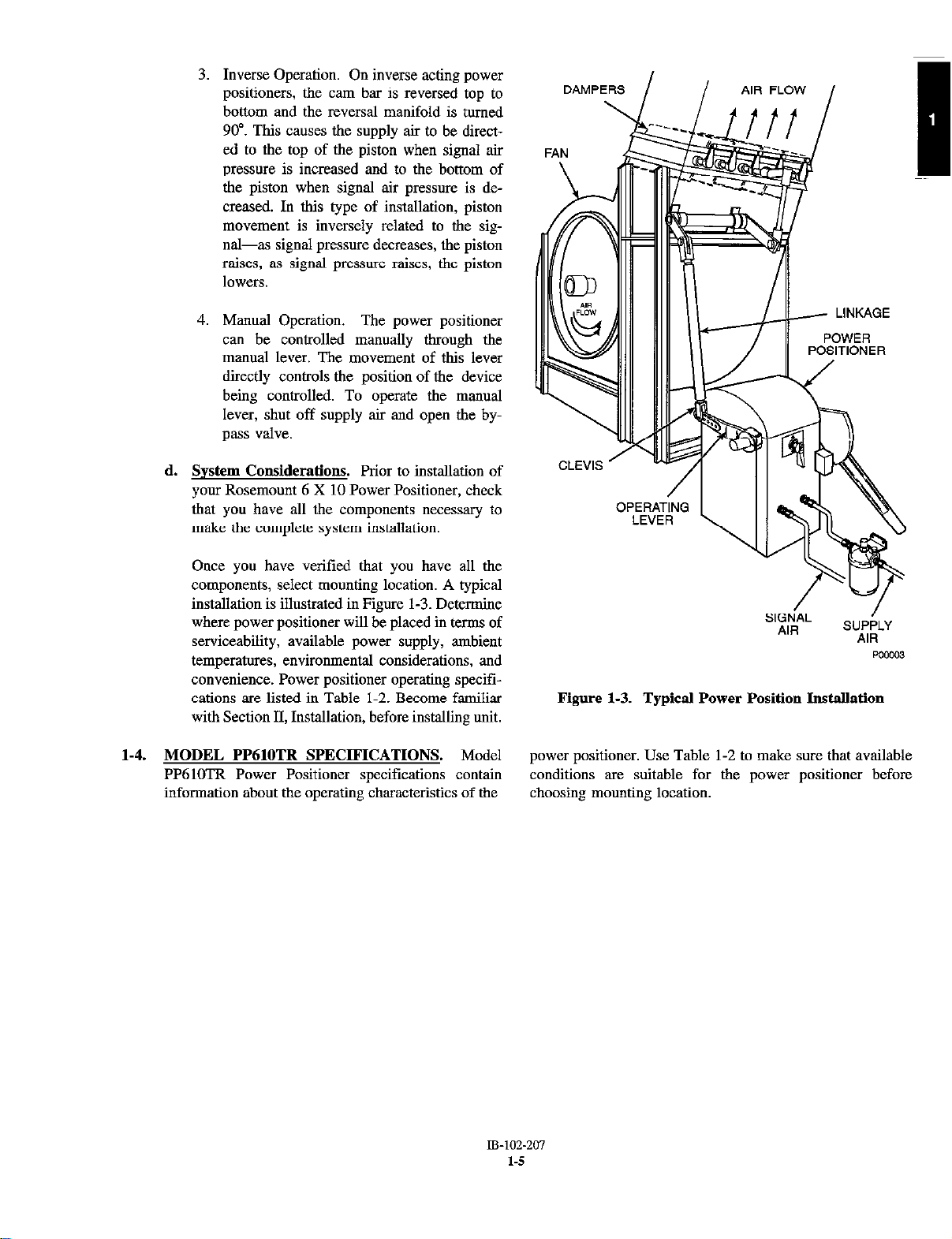
3. Inverse Operation. On inverse acting power
positioners, the cam bar is reversed top to
bottom and the reversal manifold is turned
90”. This causes the supply air to be directed to the top of the piston when signal air
pressure is increased and to the bottom of
the piston when signal air pressure is decreased. In this type of installation, piston
movement is inversely related to the signal-as signal pressure decreases, the piston
raises, as signal pressure raises, the piston
1OUWS.
4. Manual Operation. The power positioner
can be controlled manually through the
manual lever. The movement of this lever
directly controls the position of the device
being controlled. To operate the manual
lever, shut off supply air and open the by-
pass valve.
d. System Considerations. Prior to installation of
your Rosemount 6 X 10 Power Positioner, check
that you have all the components necessary to
make. the complete system installation.
POSITIONER
Once you have verified that you have all the
components, select mounting location. A typical
installation is illustrated in Figure 1-3. De&mine
where power positioner will be placed in terms of
serviceability, available power supply, ambient
temperatures, environmental considerations, and
convenience. Power positioner operating specifications are listed in Table l-2. Become familiar
with Section II, Installation, before. installing unit.
1-4. MODEL PP61OTR SPECIFICATIONS. Model
PP61OTR Power Positioner specifications contain
information about the operating characteristics of the
Figure 1-3. Typical Power Position Installation
power positioner. Use Table l-2 to make sure that available
conditions are suitable. for the power positioner before
choosing mounting location.
Page 14
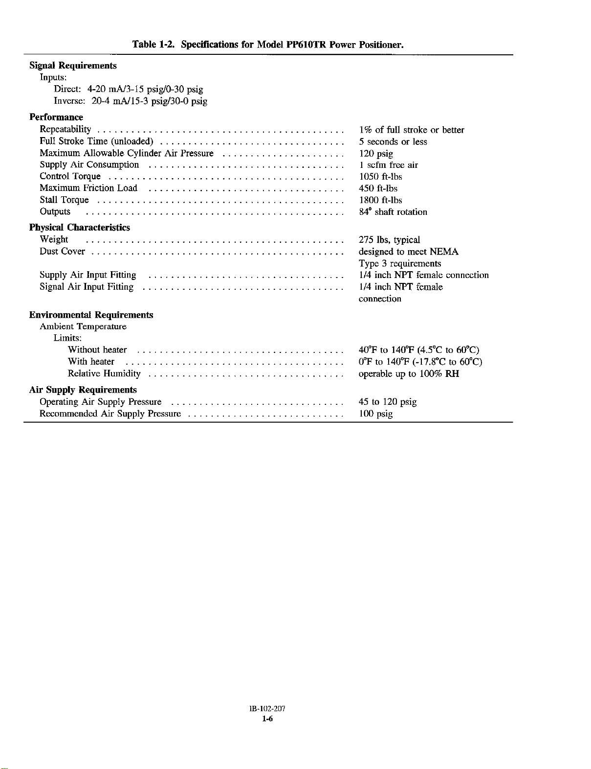
Table 1-2. Specifications for Model PP61OTR Power Positioner.
Inputs:
Direct: 4-20 mA/3-15 psig/O90 psig
Inverse: 20-4 mA/15-3 psig/30-0 psig
Performance
Repeatability
Full Stroke Time (unloaded)
Maximum Allowable Cylinder Air Pressure
Supply Air Consumption
Control Torque
Maximum Friction Load
Stall Torque
Outputs
Physical Characteristics
Weight
Dust Cover
Supply Air Input Fitting
Signal Air Input Fitting
Environmental Requirements
Ambient Temperature
Limits:
Without heater
With heater
Relative Humidity
1% of full stroke or better
5 seconds or less
120 psig
1 scfm free air
1050 ft-lbs
450 ft-lbs
1800 ft-lbs
84’ shaft rotation
275 lbs, typical
designed to meet NEMA
Type 3 requirements
l/4 inch NPT female connection
l/4 inch NPT female
connection
40’F to 140°F (4S”C to 60°C)
0-F to 140°F (-17.8”C to 60°C)
operable up to 100% RH
Air Supply Requirements
Operating Air Supply Pressure
Recommended Air Supply Pressure
45 to 120 psig
100 psiz
Page 15

1-5. STORAGE INSTRUCTIONS. Use the following
guidelines for storage of the power positioner.
a. Storage Environment. Store power positioner in
a warehouse environment that maintains the
following conditions:
1. Ambient temperatures above 45°F (7°C).
2. Humidity below 80% RH.
b. Power Positioner Preparation for Storage. Coat
all non-painted surfaces and exposed metal with a
rust-preventive compound (Tectyl 506 OI a
substitute with similar properties). The specifications for Tectyl 506 are included in Table l-3.
WARNING
CAUTION
Use only approved thinning methods when applying
rust-preventive compounds. Do not apply heat to
compound. Fire or explosion may result. Refer to
manufacture of rust-preventive compound for
specitlc application, thinning, clean-up and removal
instructions.
c. Storage Preventive Maintenance. If storing power
positioner longer than six months, observe the following preventive maintenance guidelines.
1. Cycle cylinder and piston either manually or by air
every 6 months.
Keep Tectyl506 away from heat, sparks, and open
flames and use with adequate ventibxtion. Ventilation is required for cure and to prevent an explosive
atmosphere from forming.
Table 1-3. Sp&tiications for Recommended Rust Preventive Compound.
REQUIREMENTS PROPERTIES
Approximate air dry time 1 hour
Low Temperature Flexibility -10°F (-22.5”C)
(90” bend with no flaking or cracking)
Volatile Organic Content (V.O.C.) 3.24 1bsRJ.S. Gallon
Accelerated Corrosion Tests: (5% Salt Spray (Hours))
ASTM(seeNotel)B-117atl.3mils _.......______.._.__..___. 2000
(2 x 4 x 118 inch Polished Steel Panels)
DIN (see Note 2) 50021 at 32.5 microns 168
(125 x 200 mm DIN 1623 Panels)
NOTES:
(1) ASTM (American Society for Testing and Materials)
(2) DIN (Deutsche Industrie Normen)
2. Perform General Cleaning and Lubrication (paragraph 6.3), and Cylinder and Piston, Cleaning and
Lubrication (paragraph 6-7), before installing
power positioner.
400 grams/liter
Page 16

Page 17
SECTION II. INSTALLATION
2-1. OVERVIEW. The power positioner is designed to
be installed upright The floor stand is bolted to a
prepared horizontal foundation. A minimum of 45
psig to a maximum of 120 psig supply air pressure is
needed at the mounting location. The power positioner must be controlled by either an elechicaJ signal
or by an air signal. All wiring must conform to local
and national codes.
2-2. SPECIAL INSTALLATION CONSIDERATIONS.
a.
Foundation. The power positioner’s torque is
transmitted to the operating arm of the device,
this torque is transferred to the mass of the
positioner and its foundation. The foundation
mast be designed to handle the torque produced
to keep the power positioner stationary. Refer to
paragraph 2-3 for detailed foundation require-
ments.
b.
SUPP~V
air pressure of 45 to 120 psig, minimum of 1
scfm, is required. A Nter and regulator should be
provided in the supply line.
c.
Linkaee Design Considerations. Final control
components play a large part in a control system.
Special characteristics of the device being controlled affect system response and most be reganied in design and set-up of a power positioning system.
Air Pressure Considerations. A supply
Flow tests mast be conducted before attempting
to limit damper opening. Testing is necessary to
contii actual damper characteristics and to
ensure control response throughout the entire.
flow range. When installing a new power
positioning system, care must be taken to properly design the system for linkage size and
action. In a properly designed system, a percentage change in control signal will produce the
same percentage change in flow rate. Refer to
paragraph 2-6 for detailed information on design
and installation of a linearized control action
power positioning system.
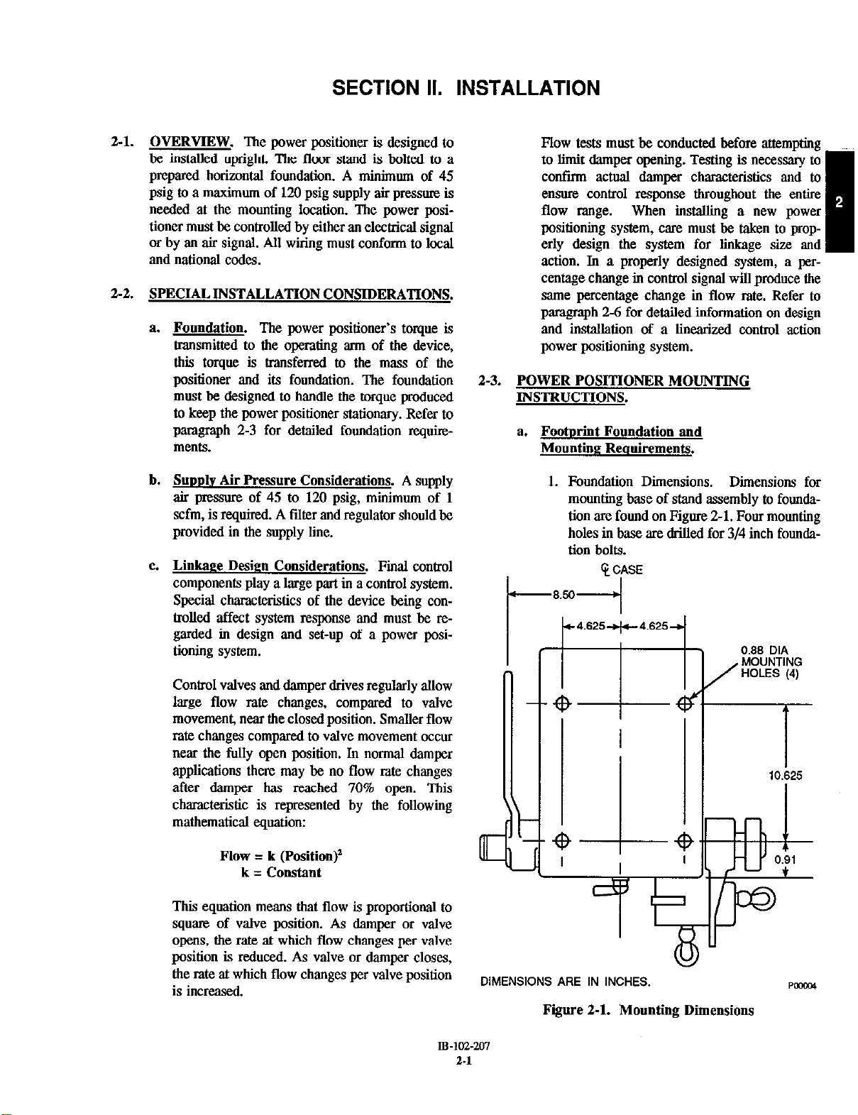
2-3. POWER POSITIONER MOUNTING
INSTRUCTIONS.
a. Footmint Foundation and
Mounting Requirements.
1.
Foundation Dimensions. Dimensions for
mounting base of stand assembly to foandation are found on Figure 2-1. Four mounting
holes in base are drilled for 3/4 inch foundation bolts.
t-
t-4.625-+-4.6254
Control valvea and damper drives regularly allow
large flow rate changes, compared to valve
movement, near the closed position. Smaller flow
rate changes compared to valve movement occur
near the fully open position. In normal damper
applications there may be no flow rate changes
after damper has reached 70% open. This
characteristic is represented by the following
mathematical equation:
Flow = k (Position)’
k = Constant
This equation means that flow is proportional to
square of valve position. As damper or valve
opens, the rate at which flow changes per valve
position is reduced. As valve or damper closes,
the rate at which flow changes per valve position
is increased.
B-102-207
DIMENSIONS ARE IN INCHES.
Figure 2-1. Mounting Dimensions
2.1
Page 18
1
14.2!
5
1
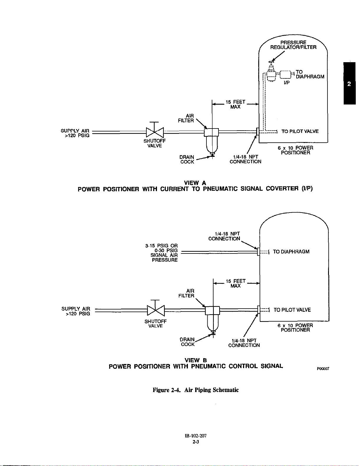
ffiter, Figure 2-4. The air filter will remove finely
dispersed water or oil droplets, preventing
sticking of the pilot valve stem.
If your unit is not equipped with an IiF’ signal
converter, a separate signal line must be installed
as shown in Figure 2-4, View B. Tbis signal line
must be either 0 to 30 psig or 3 to 15 psig. Refer
to your model number and model number matrix
(Table l-l) to determine type of air signal
required.
b. Supply Air and Signal Air Connections. Basic
schematics are shown in Figure 2-4. The
installation of the air filter is as follows:
1. Mount bracket for air filter directly on the
back of the stand assembly. If tbis is
unsuitable, mount air filter within 15 feet of
power positioner.
DIMENSIONS ARE IN INCHES.
Figure 2-2. Clearance Requirements
2. Strength Requirement. Foundation must be
able to withstand 1050 ft-lbs torque plus 250
pounds weight. Mount power positioner to
the foundation with 3/4 inch bolts.
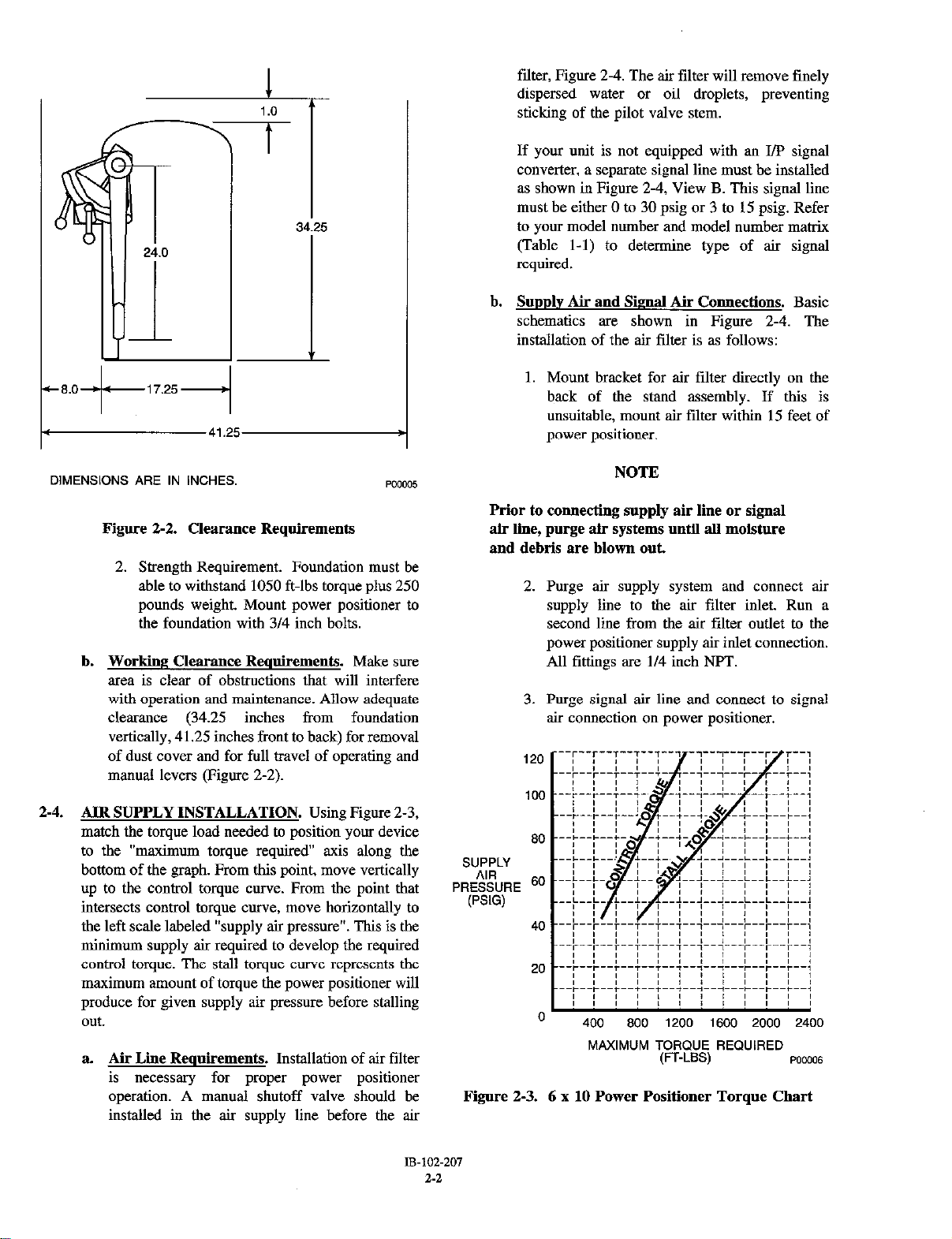
b. Working Clearance Requirements. Make sure
area is clear of obstructions that will interfere
with operation and maintenance. Allow adequate
clearance (34.25 inches from foundation
vertically, 41.25 inches front to back) for removal
of dust cover and for full travel of operating and
manual levers (Figure 2-2).
2-4. AIR SUPPLY INSTALLATION. Using Figure 2-3,
match the torque load needed to position your device
to the “maximum torque required” axis along the
bottom of the graph. From this point, move vertically
up to the control torque curve. From the point that
intersects control torque curve, move horizontally to
the left scale labeled “supply air pressure”. This is the
minimum supply air required to develop the required
control torque. The stall torque curve represents tbe
maximum amount of torque the power positioner will
produce for given supply air pressure before stalling
out.
a. Air Llle Requirements. Installation of air filter
is necessary for proper power positioner
operation. A manual shutoff valve should be
installed in the air supply line before the air
NOTE
Prior to comvxting supply air line or signal
air line, purge air systems until all moisture
and debris are blown out
2. Purge air supply system and connect air
supply line to the air filter inlet. Run a
second line from the air filter outlet to the
power positioner supply air inlet connection.
All fittings are l/4 inch NPT.
3. Purge signal air line and connect to signal
air connection on power positioner.
120
100
80
s”EiLy
PFIESES~FIE 6o
40
20
0
MAXIMUM TORQUE REQUIRED
(FT.LSS)
Figure 2-3. 6 x 10 Power Positioner Torque Chart
POW06
18-102-207
2-2
Page 19
REGULATOWFILTER
SHUTOFF
VALVE
CONNECTION
6
x 10 POWER
POSITIONER
VIEW A
POWER POSITIONER WITH CURRENT TO PNEUMATIC SIGNAL COVERTER (I/P)
SUPPLY AIR
>120
PSIG
l/4-16
CONNECTION
NPT
+--‘5tvhFT---+
AIR
FILTER
:I3 TO PILOT VALVE
l/4-18
COCK
CONNECTION
VIEW B
POWER POSITIONER WITH PNEUMATIC CONTROL SIGNAL
Figure 2-4. Air Piping Schematic
NPT
6 x IO POWER
POSITIONER
Page 20
2-5. CURRENT TO PNEUMATIC SIGNAL
CONVERTER (I/P) ELECTRICAL
CONNECTIONS. Connect electrical signal input to
I/F’ converter and calibrate if necessary, refer to
paragraph 4-3 for calibration procedures. The
connections most be made by screw terminals. If the
I/P has pigtail leads instead of screw terminals, the
connection must be made at a terminal block. Gage of
wire required is 18 gage signal wire. The signal that
wiU control the W should have a range of 4 to 20
mA at a voltage of 24 vdc.
a. Direct Acting. Connect positive signal to black
lead and negative signal to white lead.
h. Reverse Acting.. Connect positive signal to
white lead and negative signal to black lead.
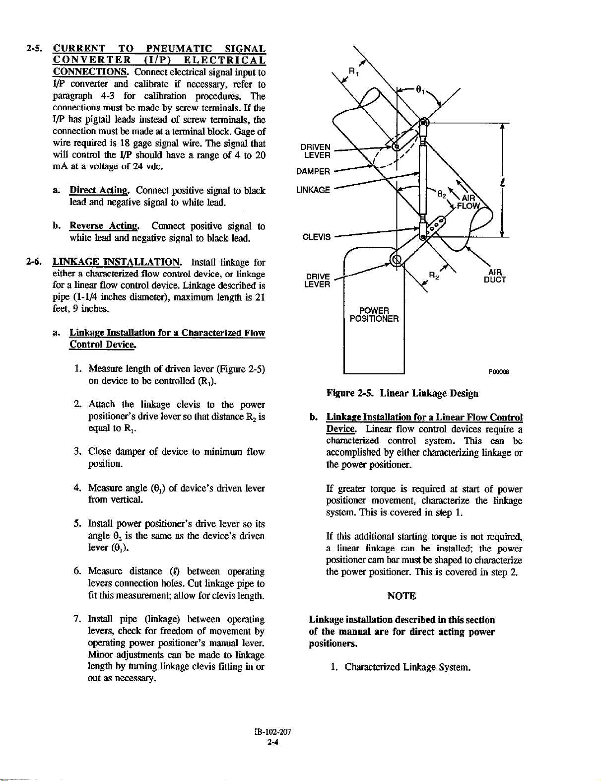
2-6. LINKAGE INSTALLATION. lnstxdl liige for
either a characterized flow control device, or linkage
for a linear flow control device. Linkage described is
pipe (l-1/4 inches diameter), maximum length is 21
feet, 9 inches.
a. Linkage Installation for a Characterized Flow
Control Device.
DRIVE
LEVER
POWER
POSITIONER
1. Measure length of driven lever (Figure 2-5)
on device to be controlled (R,).
2. Attach the linkage clevis to the power
positioner’s drive lever so that distance & is
equal to R,.
3. Close damper of device to minimum flow
position.
4. Measure angle (6,) of device’s driven lever
from vertical.
5. Inslall power positioner’s drive lever so its
angle l$ is the same as the device’s driven
lever (0,).
6. Measure. distance (p) between operating
levers connection holes. Cut linkage pipe to
fit this measoremenr allow for clevis length.
7. Install pipe (linkage) between operating
levers, check for freedom of movement by
operating power positioner’s manual lever.
Minor adjustments can be made to linkage
length by turning linkage clevis fitting in or
out as “L?ceSsary.
Pwme
Figure 2-5. Linear Linkage Design
b. Linkage Installation for a Linear Flow Control
Device. Linear flow control devices require a
characterized control system. This can be
accomplished by either characterizing linkage or
the power positioner.
If greater torque is required at start of power
positioner movement, characterize the linkage
system. This is covered in step 1.
If this additional starting torque is not required,
a linear linkage can be installed; the power
positioner cam bar must be shaped to characterize
the power positioner. This is covered in step 2.
NOTE
Linkage installation described in thii section
of the manual are for direct acting power
positioners.
1. Characterized Linkage System.
IB-102.207
2-4
Page 21
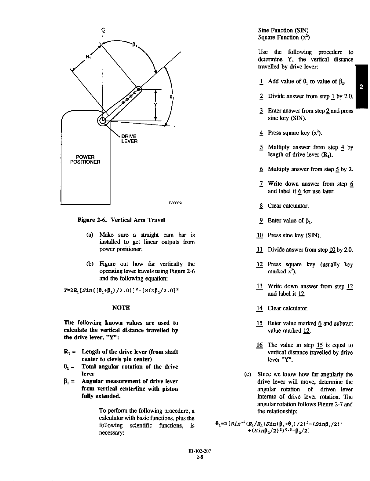
Sine Function (SIN)
Square Function (x’)
Use the following procedure to
determine Y, the vertical distance
travell.xl by drive lever:
1 Add value of 8, to value of &.
2 Divide answer from step 1. by 2.0.
3 Enter answer from step 2. aad press
sine key (SJN).
\ DRIVE
LEVER
POWER
POSITIONER
Figure 2-6. Vertical Arm Travel
(a) Make sore a straight cam bar is
installed to get linear outputs from
power positioner.
(b) Figure out how far vertically the
operating lever travels using Figure 2-6
aad the following equation:
NOTE 14 Clear calculator.
4 Press square. key (x”,.
2 Multiply answer from step 2 by
length of drive lever (RI).
6 Multiply answer from step 5 by 2.
z Write down answer from step 6
and label it 6 for use later.
& Clear calculator.
2 Enter value of pP
a Press sine key (SIN).
.lJ Divide answer from step jQ by 2.0.
12 Press square key (asaally key
marked x3.
12 Write down answer from step 12.
and lab4 it 12.
The following known values are used to
calculate the vertical distance travelled by
the drive lever
“Y”-
, .
R, = Length of the drive lever (from shaft
center to clevis pin center)
Total angular rotation of the drive
Cl1 =
lever
Angular measurement of drive lever
PI =
from vertical centerline with piston
fully extended.
To perform the following procedure, a
calculator with basic functions, plus the
following scientific fanctions, is
necessary:
IF-102-207
2-s
u Enter value marked fi aad subtract
value marked 12.
16 The value in step u is equal to
vertical distance travelled by drive
lever “Y”.
(c) Since we know how far angularly the
drive lever will move, determine the
angular rotation
of driven lever
interms of drive lever rotation. The
angular rotation follows Figure 2-7 aad
the relationship:
Page 22
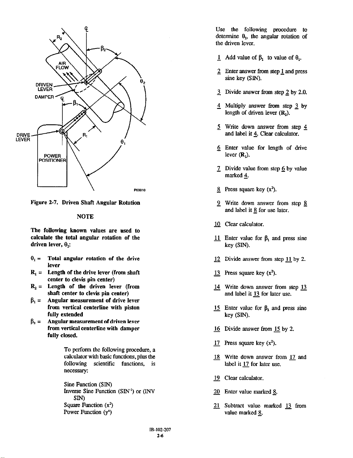
DRIVE
LEVER
use the following procedure to
determine O,, the angular rotation of
the driven lever.
1 Add value of PI to value of 8,.
2. Enter answer from step 1. and press
sine key (SIN).
3 Divide answer from step 2 by 2.0.
4 Multiply answer from step 3 by
length of driven lever (&).
2 Write down answer from step 4
and label it 2. Clear calculator.
6 Enter value for length of drive
lever (Rd.
1 Divide value. from step 6 by value
marked 5.
8 Press square key (x3.
Figure 2-7. Driven Shaft Angular Rotation
NOTE
The followiag known values are used to
calculate the total angular rotation of the
driven lever, 8,:
8, = Total angular rotation of the drive
lever
R, = Length of the drive lever (from shaft
center to clevis pin center)
& = Length of the driven lever (from
shaft center to clevis pin center)
f& = Angular measurement of drive lever
from vertical centerline with piston
folly extended
bt = Angular measurement of driven lever
from vertical centerline with damper
fully closed.
To perform the following procedure, a
cakxlator with basic functions, plus the
following scientific functions, is
lN%Xssary:
Sine Function (SIN)
Inverse Sine Function (SIN’) or (INV
SIN)
Square Function (x3
Power Function (y”)
2 Write down answer from step 8
and label it 5 for use later.
g Clear calcolator.
11. Enter value for PI and press sine
key (SW.
12 Divide answer from step 11 by 2.
12. Press square key (x”).
14 Write down answer from step .lJ
and label it 13 for later use.
u Enter value for a and press sine
key (SW.
16 Divide answer from u by 2.
12 Press square key (x2).
B Write down answer from u and
label it ,lJ for later use.
19 Clear calcllhtor.
20 Enter value marked &
21. Subtract value marked 13 tiom
value marked 8.
m-102-207
2.6
Page 23

Subtract value marked 11 from
step 21.
Press power function key (fl.
Enter 0.5.
Press inverse sine (INV SIN or
SW).
Write down answer from step 25
and label it 2.
Clear calc”lator.
Enter value for bL.
Divide value Fran step 28 by 2.
Write down answer from step 29
and label it 29. Clear calculator.
Enter value fmm step 2.
Subtract value f?om step 2.
Multiply answer from step 32 by 2.
The value in step 33 is equal to
total angular rotzl of driven
lever V,“.
(d) To calculate length of connecting
linkage based on the length of drive
lever, driven lever, and the initial offset
of both, “se Figure 2-8 and the
following relationship:
t= [I,- ~R@s~,+R#x&) ‘+
(R,SfnflI-R@$,)
NOTE
The following known values are used to
calculate the length of the linkage I in
inches:
L=
Length between drive and driven
shaft center lines
R, =
Length of the drive lever (from shaft
center to clevis pin center)
rc,=
Length of the driven lever (from
shaft center to clevis pin center)
Angular measurement of drive lever
I% =
from vertical centerline with piston
fully extended
Angular measurement of driven lever
P2 =
from vertical centerline with damper
fully closed
I o.5
Figure 2-8. Connecting Linkage Length
To perform the following procedure, a
calculator with basic functions, plus
the following scientific functions, is
“ecessaly:
Sine Function (SIN)
Cosine Function (COS)
Square Function (x’)
Power Function (y”)
Use the following procedure to
determine 4, the length of connecting
linkage in inches:
1 Clear calc”lator,
IB-10%2Q7
2.7
Page 24

Enter value for b1 and press cosine
2
key (COS).
Multiply answer from step 21 by
length of driven lever (RJ.
3 Multiply answer from step 2 by
length of drive lever (R,).
3 Write. down answer from step 2
and label 2.
2 Clear calculator.
Enter value for pz and press cosine
6
key (COS).
1 Multiply answer from step 6 by
length of drive lever (R,).
& Write answer from step 1 down
and label 1. Clear calculator.
2 Add answer from step 8 to value
marked 2.
@ Press sqnare key (x3.
11 Write down answer from step g
and label lo.
Write down answer from step 22.
and label g. Clear calculator.
Subtract value marked 22 tiom
value marked u.
Add answer from step 2 to value
marked~.
Press power function key (y”).
Enter 0.5 into calculator.
The value in step 27 is eqaal to
length of connectingiige “P “.
Design linkage system by using values
for lengths of drive aad driven levers,
angular position of both levers from
vertical (offsets), and distance between
drive and driven levers centers to
calcnlate length of lib&age. These
values were determined in the previous
steps.
12 Clear calc”lator.
13 Enter distance between drive and
driven shaft (L).
14 Subtract value marked 3 from
step JJ.
.Q Write down answer from step 14
and label H.
6 Clear calculator
12 Enter value for fil and press sine
key (SIN).
u Multiply answer from step 17 by
length of drive lever (R,).
19 Write down answer from step 18
aad label B.
20 Clear calc”lator.
21 Enter vale for fiz and press sine
key (SW.
(e) Close damper to minimum flow
position. Make sore driven lever is at
angle (PJ and drive lever is at angle
(BI).
Cat linkage pipe to length (#). Install
(0
linkage between operating levers.
(g) Check for freedom of movement by
operating power positioner’s manual
lever. Minor adjustments linkage length
can be made by turning pipe to clevis
fitting in or oat as necessary.
Record values on Figure 2-8 for p,, pz,
(h)
P, R,, and R,.
2. Characterized Power Positioner.
Determine open and closed positions of
(a)
controlled damper.
Install mechanical linkage so the power
(b)
positioner will travel through its ten
inch stroke while positioning the
damper from minimum to maximum
opening.
B-102-207
2.8
Page 25

DRIVEN
LEVER
CLEVIS
DRIVE
LEVER
POWER
POSITIONER
Install power positioner’s drive
lever at the same angle as the
device’s operating lever (El,) with
power positioner’s piston fully
extended.
MeaSUre distance between
operating levers connection holes
(0. Subtract distance of clevis
and connection to the damper’s
operating lever. Cut pipe to fit this
measorement
Install pipe (linkage) between
operating arms.
Check for freedom of movement
by operating power positioner’s
manual lever. Minor adjustments to
linkage length can be made by
tuning pipe to clevis fdtiag in or
out as necessary.
u
Fiire 2-9. Characterized Linear Linkage Design
Measure. length of driven lever
(Figure 2-9) from its shaft center
to center of clevis pin (R,).
Attach the linkage clevis to the
power positioner’s drive lever so
that distance R, is equal to R,.
Close damper of device to
minimum flow position.
Measure angle (63 of device’s
driven lever from vertical
centerline with damper closed.
Table 2-1. System Flow Chart.
INPUT
SIGNAL
10% 20%
30% 40% 50% 60% 70%
NOTE
Follow calibration procedures carefully.
Proper power positioner calibration is
essential to accurately shape the cam bar.
(c) Calibrate the stroke of power
positioner. Refer to paragraph 4-1. It is
essential to calibrate carefully.
(d) Measure and record actual flow of
system being controlled starting at zero
input signal and increasing signal in
10% increments to 100%. Record these
vahm in Table 2-1, System Flow
Chart. These values will be used later
to plot the shape of the cam bar.
80% 90% 100%
FLOW
wm
IB-IM-207
2-9
Page 26

DIMENSION
DIMENSION 6
A
t
- POW13
Figure 2-10. Cam
ROLLER AT BOTTOM
LOCK SCREW
DIMENSION C
Bar Shaping
(g) Near bottom of a sheet of graph paper,
draw a base line (Graph 1). Draw a
vertical line near left side of paper.
Label this line “% of Input Signal”.
(h) Mark point “A” to right of “% of Input
Signal” line. This point is 10 inches up
from base line and at dimension “A’
from “% of Input Signal” line.
(i) Mark point “B” to right of input signal
line. Point “B” is on base line at same
distance from “% Input Signal” line as
dimension “B”.
(i) Lay cam bar on graph with lock screw
hole at bottom. Point “A” and point
“B” as marked on cam bar should line
up with point “A” and point “B” as
plotted on graph. Draw a heavy line
thra points “A” and point “B” and label
cam bar line.
(e) Measure and record dimensions A, B,
and C as follows:
1 Using air pressure, move piston
and clevis head to bottom of
stroke. Mark point that roller
touches cam bar. This is point “A”
(Figure 2-10).
2. Measure distance from point “A”
to face of guide bar to the nearest
1/64th inch. Record thii as
dimension “A”.
2 Using air pressure, move piston
and clevis head to top of stxoke.
Mark point that roller touches cam
bar. This is point “B”.
4 Measure distance from point “B”
to guide bar to nearest 1/64th inch.
Record this as dimension “B”.
5 Dimension “C” is the distance
between guide bar to center of lock
screw. Measure to nearest 1/64th
inch.
(0 Using signal air move piston to bottom of
stroke and remove lock screw (Figure 2-10).
Remove compensating bar from positioner.
(k) Refer to Graph 2. Mark input signal
points, in 10% increments, on % of
input signal line at right edge of graph.
0% will be at the top of the graph,
Point A, and 100% will be at the base
he, Point B. Each 10% signal will be
one inch apart
(1) Draw a line from each “% Input
Signal” horizontally to cam bar line.
From this point of intersection, draw a
vertical line to top of graph. Label top
of graph “% of Horizontal Roller
Travel”.
(m) On base line, label ten points recorded
in step d that represent flow of ten
different signal positions. Record these
ten flow points along base line between
0 and 100% flow (Graph 3).
NOTE
For this purpose, we used a 100% flow of 7
scfm. At 10% iaput signal we had flow of
18 scfm, at 20% input signal we had flow
of 3.1 scfm, etc. These values noted in the
example flow chart on Graph 3.
Page 27

Graph I
% OF
INPUT
SIGNAL
80
Graph 2
: : : : :
Page 28

From base. line, draw a vertical line at
(a
10% mark of 1.8 up to where a line
would extendhorizontally from 10% “%
of Input Signal” scale. Repeat for 20%
mark of 3.1 to a line extending
horizontally from 20% “% of input
signal” scale. Continue in same fashion
for others from 30% flow mark to
100% flow mark. Draw a smooth curve
thru these points from 0% flow to
100%. Label curve “x”.
Draw a straight line from zero flow at
(0)
zero “% of Input Signal” to 100% flow
at 100% “% of Input Signal”. Label
curve “y” (Graph 4).
(p) Draw a horizontal line from 10% “%
of Input Signal” at cam bar line to
curve “Y”. Draw a line from this point
vertically to curve “x”. Draw a line
from curve “x” horizontally back to
10% of “% of Horizontal Roller
Travel” line plotted earlier. Place a
mark on this 10% line as shown in
Graph 4.
(q) Repeat step @) procedure for 20% thm
90% lines. At each point that intersects
with “% of Horizontal Roller Travel
Line”, put a mark as indicated in
Graph 5.
Graph 3
BASE
rNPuT
SIGNAL IN %
Example System Flow Chart
10 20 30 40 50 60
100%
FLOW
(7 SCFM)
PWOIS
70 80 90 100
Page 29

60
L % OF
Graph 4
i
!ERC
f
ZLOVI
BASE LINE
% OF
INPUT
SIGNAL
50
60
70
kx
I zh%L,T~,
100%
FLOW POW,,
Graph 5
ZERO
FLOW
I
\I
IB-102-207
2-13
Page 30

(r) Connect marks with a smooth curve
thm point “A” to point “B” thru each
mark recorded. This will be the
required cam bar shape.
(s) Construct a template from the plotted
curve. Mark points A and B on
template.
(t) Bend cam bar to match template.
Points A and B on template must align
with Points A and B marked on cam
bar earlier.
(u) Dtaw tile face of cam bar as necessary
to obtain a smooth carved sarface. Do
not remove marked points A and B.
(v) Install am bar on power positioner
with lock screw positioned at point C
recorded in step (e). Make sate
dimensions for points A and B match
those recorded in step (e): if necessary
adjust position of lock screw to make
dimensions A and B recoTded in
step (e).
Check results by setting 10%
increments of input signal from 0% to
100%. The flow must change in 10%
increments for 0 flow to 100% flow.
For example: with a 100% of 7 SCFM,
a 10% input signal will flow at 0.7
SCFM, 20% at 1.4 SCFM, etc.
Adjustments to the cam bar can be
made by minor bending or draw fiing.
Figure 2-11. Driven Lever Travel
Set input signal to 0%. Measure
distance controlled devices driven
lever, Figure 2-11, travels for each
10% increase in input signal: up to
100% input signal. Record these values
in Table 4-1, Characterized column as
percent of total travel. These values are
necessary for verifying calibmtion.
Set input signal to 0%. Measure
distance clevis head travels for each
10% increase; up to 100% input signal.
Measurement should be taken from
packing nut to bottom edge clevis
head. Record values measured in Table
4-2, Calibration Schedule D in the
respective columns. These values are
necessary for verifying calibration.
Page 31

SECTION III. REVERSE OPERATION
3-1. OPERATIONAL DESCRIPTION.
I” reverse
acting positioners, the piston and rod operate the same
as when setup for direct acting (Figure l-2). The cam
bar is reversed top to bottom and the reverse manifold
is tomed 90”. The repositioned manifold causes
supply air to be directed to the top of piston when
signal air pressure is increased and to the bottom of
piston when signal air pressure is decreased. In this
case, piston movement is inversely related to the
signal. A falliig signal air pressure raises the piston
and an increasing signal air pressure lowers the
piston,
3-2. PROCEDURES FOR REVERSING OPERATION.
To reverse the operation of the cylinder, refer to
Figure 3-l and use the following procedures:
a. Reverse Compensating Assemble.
1.
Close the supply air valve.
2.
Set signal air to 0.
3.
Remove screw (1) securing spring clip (2) to
compensating assembly (4). Remove spring
clip.
pilot valve (8) and its gasket (9) in the same
position as it was when removed, Secure.
pilot valve and reverse manifold in place
with mounting screws (7).
c. Calibrate Stroke.
1. Disconnect operating lever (12, Figure 3-1)
from device being controlled at clevis (13).
WARNING
Use caution when applying supply air to the
pilot valve. The air pressure will cause the
piston, rod, and operating lever to move
when the piston travels to the top of its
stroke. Personnel injury or damage to equipment may occur during sudden applications of compressed air.
2.
Open supply air valve. This will cause
piston rod (14) to move to top of its stroke.
Set signal air to minimum.
3.
Using an allen wrench, loosen lock screw
(15) holding spring socket (16).
4.
Remove two screws (3) sewing compensating assembly (4) to clevis head (5). Remove
compensating assembly.
5. Reinstall compensating assembly (4) in a
reversed position with stroke adjustment
scwv (6) at the top. Secure compensating
assembly to clevis head (5) with two screws
(3).
6. Reinstall spring clip (2).
b. Rotate Reverse Manifold.
1. Remove screws (7, Figure 3-1) securing
pilot valve (8) and reverse manifold (10) to
cylinder assembly (17). Remove pilot valve
and reverse manifold.
2. Rotate reverse manifold (10) and its gasket
(11) 90” clockwise. The arrow, stamped on
reverse manifold, should point down. Install
4.
Trim spring socket (16) counterclockwise
until piston rod (14) starts to move downward.
5.
Tam spring socket (16) slowly clockwise
until piston rod (14) reaches maximum
position.
6.
Tighten lock screw (15) to hold spring
socket (16) fvmly in place.
7.
Set signal air to its maximum amount and
check movement of piston rod (14) for fall
stroke. The piston rod should just reach bot-
tom of stroke with maximum signal to pilot.
If necessary, tam the stroke adjustment
screw (6) counterclockwiie very slowly until
full stroke is reached.
8.
Reconnect operating lever (12) to device
being controlled at clevis (13).
IB-102-207
3-l
Page 32

ITEM
1
2
3
4
5
6
I
8
9
10
11
12
13
14
1.5
lb
17
18
DESCRUTION
screw
Spring Clip
screw
Compensating Assembly
Clevis Head
Stroke Adjustment Screw
SCEW
Pilot valve
Gasket
Reverse Manifold
Gasket
Operating Lever
Clevis
Piston Rod
Lock Screw
Spring Socket
Cylinder Assembly
Packing Nut
3
-3
7-
5
DIRECT ACTING
COMPENSATING ASSEMBLY
3 -
3
6
?I
7
5
-4
6
REVERSE ACTING
COMPENSATING ASSEMBLY
Fire 3-1. Reverse Operations
WlO%207
3-2
PC.2420
Page 33

SECTION IV. CALIBRATION
4-1.
CHECK POWER POSITIONER CALIBRATION.
Use the following promlure to check calibration of
power positioner. Figure 4- 1, Calibration Flowchart is
provided as a quick reference guide.
NOTE
If cam bar was shaped (characterized),
values of percent output desired must be
recorded upon installation in Table 4-1
Schedule D. This is necessary to check
calibration. If values were not recorded,
refer to 2-6b2 and calculate correct
positions using formulas.
a. Device Travel.
1. Measure distance that the controlled device’s
driven lever arm travels from 0% signal air
to 100% signal air. Record this as total
distance.
2. Set signal air to 0%.
OF TRAVEL OF
DEVICE EQUAL TO
CORRESPONDING
PERCENTAGE OF
CHECK STROKE
POSITION FOR
EACH PERCENT
OF SIGNAL LISTED
IS PISTON IN
PROPER POSITION
FOR EACH SIGNAL
AIR PRESSURE?
3. Measure controlled device’s driven lever
arm travel from 0% to a 10% signal air.
Divide measurement by total distance from
step a. Record this as the percentage of
output travel for 10% signal air. Measure
and record percentage of output travel in the
same fashion in 10% increments up to 100%
signal air.
4. Compare recorded readings with percent
driven lever travel in Table 4-l. Use
respective columns for characterized
systems, linear, square mot, or square cam
bars. If recorded percentages of travel are
equal to those in Table 4-1 the system does
not need calibration. If recorded readings do
not equal those ia Table 4-1 continue.
checking procedure.
b. Piston Travel.
1. Set signal air to 0%.
2. Measure distance fmm top surface of
packing nut (18, Figure 3-1) to bottom
surface of clevis head (5). Label tbii
distance “A”.
CALIBRATE STROKE
AND I/p. REFER TO
PARAGRAPHS 4-2
Fire 4-1. Calibration Flowchart
3. Increase signal to 100%.
4. Measure distance from surface of packiag
nut (18) to bottom surface of clevis head (5).
Label this distance “B”.
5. Subtract distance “A” from distance “B”.
Thii is total stroke travel of the power
positioner. Record this distance as total
stroke travel.
6. Set signal air to 0%.
IB-102-207
Page 34

Table 4-1. Device Travel (%1.
PERCENT SIGNAL
AIR PRESSURE
0 0 0.0
10
20
30 30 54.8 9.0
40
50 50 70.7 25.0
60 60 77.5 36.0
70 70 83.7 49.0
80 80 89.4 64.0
90
100 100 100.0 100.0
7. Measure the piston travel (stroke) when a
10% signal is sent to the power positioner.
Record this as stroke travel for 10% signal
air. Measure and record percentage of output
travel in the same fashion in 10%
increments up to 100% signal air.
l-
PERCENT DRIVE N LEVER TRAVEL
SQUARE ROOT
LINEAR (x)
10 31.6 1.0
20 44.8 4.0
40
90
Ma
63.25
94.9 81.0
4-2. STROKE CALIBRATION. Use the following
procedures to adjust a power positioner’s stroke.
a. Direct Acting Power Positioner.
SQUARE (x3 CHARACTERIZED
0.0
16.0
stroke (paragraph 4-2) and then calibrate I/l’
(paragraph 4-3).
NOTE
Values for characterized stroke measured in
inches and percent corresponding to input
pressures are recorded in Table 4-2
Schedule D. If values were not recorded,
refer to 2-613.2. and calculate correct
positions using formdas.
8. Compare actual stroke movement with
desired stroke movement. Desired stroke
movements appear in Table 4-2, Calibration
Schedule. Schedule “A” is for a linear cam
bar, “B” for a square root cam bar, “c” for
a square cam bar, and “D” for a
characterized cam bar. If actual stroke of
power positioner is equal to desired value in
Table 4-2, refer to paragraph 4-5 and
calibrate linkage. If it is not equal, calibrate
1. Purge air lines to remove any water or
debris.
2. Making sure that by-pass valve is closed, set
signal air to minimum stroke position (0%).
Refer to Table 4-3 for percent stroke to
signal air conversion.
3. Loosen lock screw (1, Figure 4-2) holding
spring socket (2) in place. Turn spring
socket counterclockwise until piston rod (3)
begins moving up from bottom of stroke.
Turn spring socket slowly clockwise until
piston rod moves to lowest position. Tighten
lock screw.
4. Increase signal air to maximum (100%).
Refer to Table 4-3 for percent to signal air
conversion.
Page 35

o-60 PSig m
0
6
12
18
24
30
36
42
48
54
60
0
6
12
18
24
30
36
42
48
54
60
0
6
12
18
24
30
36
42
48
54
60
0
6
12
18
24
30
36
42
48
54
60
3-15 pstg
3.0
4.2
5.4
6.6
7.8
9.0
10.2
11.4
12.4
13.8
15.0
CP
3.0
4.2
5.4
6.6
7.8
9.0
10.2
11.4
12.4
13.8
15.0
3.0
4.2
5.4
6.6
7.8
9.0
10.2
11.4
12.4
13.8
15.0
CAL
3.0
4.2
5.4
6.6
7.8
9.0
10.2
11.4
12.4
13.8
15.0
Table 4-2. Piston Travel (Stroke) Calibration Schedule.
CALIBRATION SCHEDULE “A” - LINEAR CAM BAR
INPUT SIGNAL
O-30 psig
0
3
6
9
12
15
18
21
24
27
30
:RATION SCHEDI
0
3
6
9
12
15
18
21
24
27
CA
tATION SCHEDUL
30
LIBRATION SCHI - 3DU1
0
3
6
9
12
15
18
21
24
27
30
0
3
6
9
12
15
18
21
24
27
30
Percent of Signal
0%
10%
%
30%
40%
50%
60%
70%
80%
90%
100%
“B” - SQUARE R<
0%
10%
20%
30%
40%
50%
60%
70%
80%
90%
10%
1
LE “C” - SOUARE CAM BAR
0%
10%
20%
30%
40%
50%
60%
70%
80%
90%
100%
D” - CHARACTER
0%
10%
20%
30%
40%
50%
60%
70%
80%
90%
100%
Inches
)O
l’CAMBAR
ED CAM BAR
0.M)
la0
2.00
3.00
4.00
5.00
6.@3
7.00
8.00
9.03
1om
0.00
3.16
4.48
5.48
6.325
7.07
7.75
8.37
8.94
9.49
10.00
0.00
0.10
0.40
0.90
1.60
2.50
3.60
4.90
6.40
8.10
1oM)
DESlRl
CD STROKE
Percent of Full Stroke
0%
10%
20%
30%
40%
50%
60%
70%
80%
90%
lco%
O.co%
31.60%
44.80%
54.80%
62.25%
70.70%
77.50%
83.70%
89.40%
94.90%
100.00%
0%
1%
4%
9%
16%
25%
36%
49%
64%
81%
100%
IB-102-207
4.3
Page 36

ITEM DESCRIPTION
1 Lock Screw
2 Spring Socket
3 Piston Rod
4 Lock Bolt
Stroke Adjustment
NOTE
If stroke length needed is less than standard
10 inches, adjustment of stroke adjustment
screw cau decrease stroke length to seven
inches.
Loosen stroke adjustment screw lock bolt (4,
5.
Figure. 4-2). Tam stroke adjustment screw
(5) clockwise until piston rod moves
downward. Tam screw in opposite direction
until piston rod moves to maximum position
or to desired length of travel. Tighten lock
bolt (4).
h. Inverse Acting Power Positioner.
1.
Purge air lies to remove any water or
d&is.
2.
Making sure that by-pass valve is closed, set
signal air to maximum (100%). Refer to
Table 4-3 for percent to signal conversion.
3.
Loosen lock screw (1, Figure 4-2) holding
spring socket (2) in place. Turn spring
socket clockwise until piston rod (3) begins
moving up from bottom of stroke. Tom
spring socket slowly clockwise until piston
rod moves to lowest position. Tighten lock
SCIZW.
Fire 4-2. Stroke Adjustment
Table 4-3. Direct and Inverse Calibration Signal Pressures.
POWER POSITIONER ACTION
STROKE
POSITION
DIRECT INVERSE
PNRUMATIC UP PNEUMATIC I/P
0 - 30 psig 3 - 15 psig O-60 0
0% 0 3 0
100% 30 15 60
4.
Decrease signal air to minimum (0%). Refer
to Table 4-3 for percent to signal
conversion.
- 30 3 - 15 0 - 60 psig
Psig psig Psig
30 15 60
0 3 0
LB-N-207
4.4
Page 37

NOTE
If stroke length needed is less than standard
10 inches, adjustment of stroke adjustment
screw can decrease stroke length to SEVEN
inches.
5. Loosen stroke. adjustment screw lock bolt
(4). Turn stroke adjustment screw (5)
counterclockwise until piston rod (3) moves
downward. Turn screw in opposite direction
until piston rod moves to maximum position
or to desired length of travel. Tighten lock
bolt (4).
4-3.
CURRENT TO PNEUMATIC (I/P) SIGNAL
CONVERTER CALIBRATION. Calibrate current
to pneumatic signal converter after mounting,
changing mounted position, or when loss of control is
noticed (refer to Troubleshooting, Section V). Use the
following procedures to calibrate the signal converter:
a. Remove plastic caps from “Zero” and “Span”
adjustment holes (Figure 4.3).
NOTE
Make sure the input pressure rating of the
power positioner is the same as the pressure
rating stamped on the current to pneumatic
signal converter.
b.
Set signal value to 4 mA (20 mA if I/p is in an
inverse setup) and adjust “zero” screw until
output pressure is at 0 psig. Turn SCIW
counterclockwise to increase pressure, clockwise
to decrease pressure. If output pressure does not
change when screw is turned, turn screw
counterclockwise until pressure starts to rise.
PRESSURE
GAUGE
Figure 4-3. Current to Pneumatic Signal Converter
4-4. LINKAGE CALIBRATION.
a. Linear
A
Check angular travel of power
positioner’s drive. lever at cl&s. Compare this to
device’s driven lever angular travel. If angular
distances are not the same, use the following
procedure to adjust offset of power positioner’s
drive lever to tbe same angle as tbe device’s
driven lever. When adjustment is complete, both
operating levers must be parallel with each other.
Measure angle p, from vertical line
extending from shaft hub, to power
positioner’s drive lever (Figure 4-4). This is
the power positioner’s drive lever offset.
POW23
c.
Set signal value to 20 mA (4 mA if I/p is in an
inverse setup). Adjust “Span” screw until output
pressure is at 60 psig.
d.
Repeat steps b and c until no further adjustment
is needed.
e.
Replace protective caps.
Measure angle b2 from vertical line
extending from device lever’s hub, to driven
lever of device being controlled. This is the
driven lever offset.
Compare angle PI and angle. bz. Adjust
length of linkage for minor adjustments by
threading pipe in or out of clevis. Change
drive lever angle p, for major adjustments.
IB-102-207
4-s
Page 38

4. Measure length of power positioner’s drive
lever (R,) from shaft center to center of
clevis pin.
5. Measure length of device’s driven lever (RJ
from shaft center to center of clevis pin.
DRIVEN
LEVER
DRIVE _
LEVER
POWER
FOSITIONER
Figure 4-4. Linear Linkage Calibration
b. Characterized. Verify linkage design angles and
length against actual installation. Use the
following procedure, Figure 4-5, and adjust
angles and lengths as necessary.
6. Compare angle B,, b2, distance P, and
lengths R, and R2 with setup dimensions and
angles recorded in Figure 2-8. If setup
dimensions and angles were not recorded,
use formula’s in Section II to calculate
correct design for the positioning system and
record on Figure 2-8. Adjust length of
linkage for minor adjusbnents by threading
pipe in or out of clevis. Change operating
arm angle b, for major adjustments.
1. Measure angle /3, from vertical lie
extending from shaft hub to power
positioner’s drive lever. Tbii is the power
positioner’s drive lever offset.
2. Measure angle b2 from vertical line
extending from device lever’s hub to driven
lever of device being controlled. This is the
driven lever offset.
3. Measure length between connecting levers.
This distance is represented by the letter P.
IB-102-207
Figure 4-5. Characterized Linkage Calibration
4.6
Page 39

SECTION V. TROUBLESHOOTING
5-1. OVERVIEW. Troubleshooting of common problems 5-2. TROUBLESHOOTING CHART. Refer to
is provided for in troubleshooting chart (Table 5-l). Table 5-1.
The chti describes common problems, foUowed by
tbe related probable cause, and fmally by what action
is necessary to correct the defect.
Table 5-1. Troubleshooting Chart.
PROBLEM CAUSE
1. Erratic operation Pilot valve sticking.
Linkage binding or loose.
2. No response from power Manual lock engaged
positioner to a signal air
pressure change
Air supply shutoff valve closed.
Ruptured receiver diaphragm.
3. Power positioner does not Cylinder head gasket leak.
remain at set-point; continues to
cycle
Bypass valve air connection
loose.
Bypass valve leaking internally.
4. System over shoots or under I/F- out of
shoots set-point calibration.
VP failure.
CORRECTION
Clean or replace pilot valve. Refer to
paragraph 6-4 for cleaning proce
dares and paragraph 7-2~ for
replacement procedures.
Liige pivot joints corroded, dirty,
or worn. Clean and lubricate or replace parts.
Disengage manual lock.
Open air supply valve.
Replace diaphragm. Refer to
pamgraph 7-2d.
Replace leaking gasket. Refer to
paragraph 7-2e.
Tighten or replace air connection.
Replace bypass valve.
Calibrate I/F’. Refer to paragraph 4-3.
Replace I/P per paragraph 7-2b.
Piston stroke travel not properly
set.
Cam bar bent.
Pin hole in diaphragm.
5. Sluggish operation Air fdter/separator foU of water,
oil, or sediment.
Air fdter dirty.
Ambient temperature is lowe]
than the power positioner is
designed for.
6. Power positioner operates Device being controlled has a
normally but flow that is being
broken valve stem or connection
controlled remains unchanged to the linkage.
ES-102-207
.5-l/5.2
Calibrate stroke travel of piston.
Refer to paragraph 4-2.
Replace cam bar. Refer to paragraph
7-2h.
Replace diaphragm. Refer to
paragraph 7%.
Drain air filter/separator. Refer to
paragraph 6-5.
Replace filter element. Refer to
paragraph 7%.
Install power positioner heater.
Repair or replace controlled device.
Page 40

Page 41

SECTION Vi. PERIODIC MAINTENANCE
6-1. OVERVIEW. This section describes preventive
maintenance for the Rosemount Model PP61OTR
Power Positioner. Preventive maintenance. is
necessary at specific intervals to reduce wear and tear
on the power positioner.
WARNING
Before performing any maintenance or
repair action on power positioner, shut off
supply air, signal air, and any electrical
supply or electronic signals to power
positioner. Isolate power positioner from alI
systems connected to tbe power positioner.
Severe injury or death may result from
large torque power positioner is capable
of producing, or from electrical shock.
6-2. MAINTENANCE SCHEDULE. Use the
maintenance schedule, Table 6-1, as a guideline for
preventive maintenance. The frequency of this
maintenance varies directly with plant conditions and
operational load on the power positioner. Extremely
dusty conditions or high temperahnes will require.
more frequent maintenance on the power positioner.
6-3. GENERAL CLEANING AND LUBRICATION.
Clean power positioner’s exterior of all grease
buildup with commercial dry cleaning solvent. To
lubricate power positioner, refer to Figure 6-1,
Lubrication Chart.
WARNING
Clean power positioner in a well ventilated
area. Avoid inhalation of solvent fumes and
prolonged exposurt! of skill to cleaning
solvent. FoBow alI instructions on the
Material Safety Data Sheet (MSDS) of the
solvent being used. Severe injury or death
may result from improper usage.
6-4. PILOT VALVE CLEANING AND INSPECTION.
In normal service, the pilot valve assembly (Figure
6-2) requires cleaning and inspection at intervals of
approximately six months, or upon any indication of
sticking.
WARNING
Before performing any maintenance or
repair action on power positioner, shut off
supply air, signal air, and any electrical
supply or electronic signals to power
positioner. Isolate power positioner from all
systems ccnmected to the power positioner.
Severe iojury or death may result from
large torque power positioner is capable
of producing, or from electrical shock.
a. Remove power positioner from service.
I
Time Interval (Approximate)
6 months
6 months
6 months
2 years
2 years
Table 6-1. Maintenance Schedule.
Maintenance Action
Perform general cleaning and lubrication. Refer to paragraph 6-3.
Clean and inspect pilot valve. Refer to paragraph 6-4.
Clean and drain air filters. Refer to paragraph 6-5.
Clean and inspect diaphragm. Refer to paragraph 6-6.
Lubricate and clean cylinder and piston assemblies. Refer to paragraph 6-7.
Page 42

LUBRICATION CHART
f9
GREASE GUN FILLED WITH
MclUBE M&.-793
SEE NOTE 1.
t&LUBE M&-793
SEE NOTE 2.
NOTE 1: USING A GREASE GUN, LUBRICATE
ZERK FIrrINGS AT PISTON ROD
CLEVlS PIN, TRUNN!ON SCREW,
AND SHAFT ASSEMBLY.
NOTE 2: WIPE PISTON ROD WITH A CLEAN
Figure 6-1. Lubrication Chart
PISTON ROD
CLEWS PIN
TRUNNION
SCREW
SHOP TOWEL. APPLY A LIGHT COATING
OF t&LUBE MOS 793. WIPE EXCESS
GREASE OFF W&H CLEAN SHOP
TOWEL.
po(xi
IB-102.207
6.2
Page 43

ITEM
10
11
12
13
DESCRIPTION
1
Stem Assembly
2
Connecting Link
3
Ball Socket Nut
4
Air Supply Tubing
5
Elbow
6
cap screws
7
Reverse Manifold
8
Cylinder Assembly
9
valve cap
Exhaust Silencer Plug
Pilot Valve Body
Pilot Valve Gasket
Reverse Manifold Gasket
Figure 6-2. Pilot Valve Exploded View
b.
Carefully hold upper end of pilot valve stem
assembly (1, Figure 6-2). Free connecting link (2)
from pilot valve stem by turning connecting link
e. Remove valve cap (9), stem assembly (l), and
exhaust silencer plug (10) from pilot valve body
(11).
ball socket nut (3) counterclockwise.
e. Disconnect air supply tubing (4) from elbow (5). WARNING
d. Remove cap screws (6), that secure pilot valve
and reverse manifold (7) to cylinder assembly
(8). Remove pilot valve and reverse manifold.
Note alignment of pilot valve, arrow on ~cverse
manifold, and cylinder.
CAUTION
Do not use an abrasive for cleaning the
valve stem assembly or valve body.
Abrasives even as fine as crocus cloth will
cause scratches in the stem assembly and air
to leak by pilot valve stem assembly.
I&102.207
Clean pilot valve in a well ventilated area.
Avoid inhalation of solvent fumes and
prolonged exposure of skin to cleaning
solvent. Follow all instructions on the
Material Safety Data Sheet (MSDS) of the
solvent being used. Severe injury or death
may result from improper usage.
f. Thoroughly clean pilot valve body (1 l), valve cap
(9) and stem assembly (1) in commercial dry
cleaning solvent. Allow pilot valve to completely
air dry. Do not use abrasive of any kind on stem.
6-3
Page 44

g. Thoroughly clean exhaust silencer plug (10) in
commercial dry cleaning solvent, making sure it’s
exhaust port.9 m open.
NOTE
pilot valve stem and body are a matched
set. If eitber b damaged or wora to a nonserviceable condition, entire pilot valve mast
be replaced.
h. Inspect stem assembly (1) and pilot valve body
(11). If any signs of wear or damage are found,
replace pilot valve.
is not reaching set points. Refer to Figure 6-3 and “se
the following procedure.
WARNING
Before performing any maintenance or
repair action on power positioner, shut off
supply air, signal air, and any electrical
supply or electronic signals to power
positioner. Isolate power positioner from all
systems connected to tbe power positioner.
Severe injury or death may result from
large torque power positioner B capable
of producing, or from electrical shock.
i. Install stem assembly (1) into valve body (11).
Install exhaust silencer plug (10) and valve cap
j.
(9) on pilot valve hody (11).
k. Install reverse manifold (7) and assembled pilot
valve with pilot valve gasket (12) and reverse
manifold gasket (13), securing with cap screws
(6). Make sure arrow stamped on reverse
manifold (7) is pointing in the direction that the
piston rod moves with a” increasing signal air
pressure.
1. Carefully hold upper end of pilot valve stem
assembly (1). Attach connecting link (2) to pilot
valve stem assembly by tuning connecting link
ball socket nut (3) clockwise.
m. Calibrate. stroke of power positioner (refer to
paragraph 4-2).
n. Return power positioner to service.
6-5. AIR FILTER CLEANING AND DRAINING. In
nornxd service, supply air falter and signal air
fdter/regulator require draining of water and debris at
least every 6 months. The frequeny of thii
maintenance will depend on supply system air quality.
After installation, drain both falters by slowly opening
tilter and filter/regulator petcock valves. Initially drain
monthly, gradually increasing time between draining.
Schedule periodic draining when filters are
approximately l/4 full. Continue draining water and
debris at this interval unless plant supply air
conditions change. If element in air filter is dirty,
refer to Section WI for replacement procedure.
6-6. DIAPHRAGM CLEANING AND INSPECTION.
Disassemble, clean, and inspect diaphragm assembly
approximately every two years or if power positioner
a. Remove power positioner from service.
b. Remove screws (1, Figure 6-3) secwing
diaphragm cover (2) to receiver body (3).
c. Remove zero balance spring (4) from top of
diaphragm.
d. Using a clean shop towel, thoroughly wipe off
any dirt or debris on upper side of diaphragm (5).
e. Visually inspect diaphragm. Replace if nicks,
cuts, or hardened rubber areas (from excess heat)
are visible. Refer to Section VII for replacement
procedures.
f. Clean diaphragm cover (2) and zero balance
spring (4) with commercird dry cleaning solvent
and allow to air dry.
g. Align the edges of diaphragm (5) with stop ring
(6) to make a” air tight seal. Replace zero
halance spring (4).
h. Making sore the diaphragm is not folded or
pinched, replace diaphragm cover (2) and align
sealing edge of diaphragm cover on top of edge
of diaphragm.
i. Secure diaphragm cover (2) with screws (1).
Tighten all screws hand tight Snug screws down
making we that all screws get tightened evenly.
Finally complete installation by torquing to 39
foot-pounds (5.39 kg-m), tightening in a” across
the diaphragm cover sequence.
j. Test for air leakage around diaphragm cover and
receiver body. Use a leak detector, such as
“Snoop”, and apply an air signal to power
positioner. If leak is detected, repair as necessary.
lB-IM-207
6.4
Page 45

ITEM DESCRIPTION
1 screw
2
Diibmgm cover
3 Receiver Body
4 Zero Balance Spring
5 Diaphragm
6 stop Ring
Figure 6-3. Diaphragm Exploded View
k. Return power positioner to service.
6-7. CYLINDER AND PISTON. CLEANING AND
INSPECTION. Disassemble, clean and lubricate
piston and cylinder assembly approximately every two
years. Refer to Figure 6-4 and use the following
procedure.
WARNING
Before performing any maintenance or
repair action on power positioner, shut off
supply air, signal air, and any electrical
supply or electronic signals to power
positioner. Isolate power positioner from all
systems connected to the power positioner.
Severe injury or death may result from
large torque power positioner is capable
of producing, or from electrical shock.
a. Remove paver positioner from service.
b. Shot supply air valve and set signal air pressure
to 0 psig. Open bypass valve.
WARNING
Residual air must be bled off of piston
cylinder before removal of cylinder head. If
air is not bled off, eye injury may result
Bleed residual air from cylinder through pilot
c.
valve supply air connection.
Remove hex head cap screws (1, Figure 6-4) and
d.
spring clip (2).
e.
Remove hex head cap screw (3), socket head
screw (4), and remove compensating assembly
(5) from clevis head (9).
f.
Remove set screws (6) securing clevis head pin
(7).
Support cylinder assembly (18) with 2 x 4 inch
g.
board long enough to provide leverage. This will
prevent it from tipping over when clevis pin is
removed. Remove clevis pin and move shaft
lever (19) out of the way.
IB-m-207
6-S
Page 46

ITEM DESCRIPTION
1 Hex Head Cap Screw
2 Spring clip
3 Hex Head Cap Screw
4 Socket Head Screw
5 Compensating Assembly
6 Set screws
7 Cl&s Head Pin
8 Clevis Nut
9 Clevis Head
10 set screw
11
Packing Nut
12 Wiper
13 SCWUS
14 Top Cylinder Head
15 Piston Head
16 Piston
17 Top Cylinder Head Gasket
18 Cylinder Assembly
19 Shaft Lever
Figure 6-4. Cylinder Exploded View
I&102-207
6-6
Page 47

h. Remove screws (13) securing top cylinder head
(14) to cylinder assembly (18).
0.
Screw packing nut (11) onto top cylinder head
and secure with setscrew (10).
i. Pulling on clevis head (9), pull piston assembly
and top cylinder head out of cylinder assembly.
Remove and discard top cylinder head gasket
(17).
CAUTION
Do not pull piston and shaft assembly out of
cylinder head. Damage to gland bushing and
V-packing may occur.
Clean old grease off of piston (16) and piston rod
j.
(15). Wipe with dry cleaning solvent and pack
concave area of piston with McLube MO&793.
k.
With a clean shop towel and commercial dry
cleaning solvent, wipe interior surface of cylinder
assembly (18). Allow to air dry completely
before reassembling cylinder.
1.
Wipe piston rod (15) with a clean shop towel and
apply a light coating of McLube MoS,-793. Wipe
excess grease off with clean shop towel.
m.
Remove setscrew (10) securing packing nut (11)
and remove packing nut. Pack area around wiper
(12) with McLube MO&793.
n.
Replace gland bushing if it appears damaged or
was leaking. Refer to Section VII for replacement
procedures.
Install top cylinder head (14) and piston assembly
P.
with new top cylinder head gasket (17), onto
cylinder assembly (18). Secure top cylinder head
to cylinder with screws (13).
Insert end of shaft lever (19) into slot of clevis
9.
head (9).
r.
Align holes in clevis head with hole in shaft
lever. Drive clevis head pin (7) in securing cl&s
head (9) to shaft lever (19). Lock clevis head pin
in position with setscrews (6).
s.
Install compensating assembly (5) to clevis head
(9) with socket head screw (4) and hex head cap
screw (3). Install spring clip with hex head cap
screw (1).
t.
Open supply air valve and test for air leakage
around top cylinder head (14). Use a leak
detector, such as “Snoop”, and send an air signal
to power positioner. If leak is detected, repair as
necessary.
Il.
Calibrate power positioner stroke; refer to Section -
IV. Return power positioner to service..
I
Page 48

Page 49

SECTION VII. CORRECTIVE MAINTENANCE
7-1. OVERVIEW. This section describes corrective
maintenance of the Rosemount PP61OTR Power
Positioner. If specific cause of problem is not known,
refer to Section V, Troubleshooting. Spare pats
referred to arc available from Rosemount. Refer to
Section VIIJ of this manual for part numbers and
ordering information.
WARNING
Before performing any maintenance or
repair action on power positioner, shut off
supply air, signal air, and any electrical
supply or electronic signals to power
positioner. Jsolate power positioner from all
systems connected to the power positioner.
Severe injury or death may result from
large torque power positioner is capable of
producing, or from electrical shock.
7-2. PARTS REPLACEMENT.
2
a. Air Filter. Regularly inspect disposable filter
elements as needed according to plant air supply
quality. If filter element needs to be replaced,
new elements are. available. from the factory. Use
the following procedure to replace the filter
element.
1. Remove power positioner from
service.
2. Open air filter’s drain valve (1, Figure 7-l)
and bleed any air pressure and moisture
remaining in the system.
3. Remove air filter’s sump (2) by removing
cap nut (3) and cap nut gasket (4) on top of
air filter. Save cap nut gasket for
installation.
4. Remove used filter element (5) by grasping
and pulling it downward.
5. Install new fdter element (5). 8. Return system to service.
1
ITEM DESCRIPTION
1 Drain Valve
2 sump
Cap Nut
3
4 Cap Nut Gasket
Filter Element
5
6 Filter Housing
Figure 7-1. Air Filter
6. Install air filter sump (2) on to body. Secure
sump with cap nut (3) and cap nut gasket
(4).
7. Open supply air shut off valve and check for
leaks.
POW30
Page 50

b. I/p Converter. Use the following procedure for
replacement of the current to pneumatic signal
cO”“ater (I/P).
WARNING
11. Calibrate I/F and return ““it to service.
Refer to paragraph 4-3 for calibration
procedures.
c. Pilot Valve. Use the following procedures to
replace the pilot valve.
Before performing any maintenance or
repair action on power positioner, shut off
supply air, signal air, and any electrical
supply or electronic signals to power
positioner. Isolate power positioner from all
systems connected to the power positioner.
Severe injury or death may result from
large torque power positioner is capable of
producing, or from electrical shock.
1. Remove power positioner from service.
2. Turn electrical signal transmitter off and
make sure no voltage or current is being
applied to the I/p.
3. Bleed off air pressure through connection of
signal tubing to I/P.
4. Remove inlet and outlet piping to I/P.
5. Remove input signal leads from I/p’s screw
Co”“ectors. If screw COn”eCtOrs are not
installed on I/P, remove IP pigtails from
screw co”“ectors.
6. Remove screws securing old I/F’ converter to
mounting bracket and discard I/P.
I. Attach inlet and outlet piping to respective
ports on VP.
8. Connect leads to electrical signal wires. For
direct acting power positioners connect the
positive signal to black lead and negative
signal to white lead. For reverse acting
power positioners, connect positive lead to
white signal and negative lead to black
signal.
9. Install new I/P to same mounting location,
securing with screws.
10. Open supply air valves and test for leaks
“sing “Snoop” type leak detector.
WARNING
Before performing any maintenance or
repair action on power positioner, shut off
supply air, signal air, and any electrical
supply or electronic signals to power
positioner. isolate power positioner from all
systems connected to the power positioner.
Severe injury or death may result from
large torque power positioner is capable of
producing, or from electriczd shock.
1. Remove power positioner from service.
2. Carefully hold upper end of pilot valve stem
assembly (1, Figure 7-2) with pliers. Free
connecting link (2) from pilot valve stem
assembly by turning connecting link’s hall
socket nut (3) counterclockwise.
3. Disconnect supply air tubing (4) from elbow
(3.
4. Remove cap screws (6) that secure pilot
valve (7) and reverse manifold (8) to
cylinder assembly (9). Remove pilot valve
and rwerse manifold. Note alignment of
pilot valve, arrow on reverse manifold, and
cylinder.
5. Install reverse manifold (8) and pilot valve
(7) with pilot valve gasket (10) and reverse
manifold gasket (11), securing with cap
screws (6). Make sure arrow stamped on
manifold is pointing in the direction that
piston rod moves with a” increasing signal
air pressure.
6. Carefully hold upper end of pilot valve stem
assembly (1). Attach connecting link (2) to
pilot valve stem assembly by turning
connecting link ball socket nut (3)
clockwise.
7. Refer to Section N and calibrate stroke of
power positioner.
8. Return power positioner to service.
lBlO2-207
7-2
Page 51

ITEM DESCRIPTION
Stem Assembly
1
Connecting Link
2
Ball Socket Nut
3
4
Supply Aii Tubing 6292A08Hl2
5
Elbow
6
cap screws
7
Pilot Valve
8
Reverse Manifold
9
Cylinder Assembly
10
Pilot Valve Gasket 5057.002
11
Reverse Manifold Gasket
PART NUMBER
6639-003
1791.21
771B867H05
7004lAHO57
6639405
225920
263C3387GOl
125909
Figure 7-2 Pilot Valve
d. Diaphragm and Calibration Spring. Use the
following procedure for replacement of the
receiver’s diaphragm and replacement of
calibration spring. If replacing the diaphragm
only, skip steps 6 and 7. If replacing calibration
spring only, skip steps 8 and 9.
WARNING
Before performing any maintenance or
repair action on power positioner, shut off
supply air, signal air, and any electrical
supply or electronic signals to power
positioner. Isolate power positioner from all
systems connected to the power positioner.
Severe injury or death may result from
large torque power positioner is capable of
producing, or from electrical shock.
1. Remove power positioner from service.
2. Disconnect signal air tubing (2, Figure 7-3)
and remove elbow (1).
3. Remove screws (3) securing diaphragm
cover (4) to receiver body.
4. Remove zero balance spring (5) from top of
diaphragm.
5. Carefully hold upper end of pilot valve stem
assembly (25) with pliers. Free. spring
connecting link (12) from pilot valve stem
by tuning ball socket nut (13)
counterclockwise.
Page 52

ITEM DESCRIPTION
1
Elbow
2 Signal Air Tubing
3
SCKW
4 Diaphragm Cover
5 Zero Balance Spring
6 Diaphragm Stud
I Diaphragm
8 Stop Ring
9 Shield
10 Nut
11 Ball Socket Nut
12 Spring Connecting Link
13 Ball Socket Nut
14 Compensator Assembly
15 Roller
16 Fillister Head Screw
17 Hex Head Cap Screw
18 Receiver Body
19 TllJIliOIl
20 Tmnion Screw
21 set screw
22 Calibration Spring
23 Spring Washer
24 Spring Nut
25 Stem Assembly
PART NUMBER
771B867HOS
6292AOSH13
1200X8-015
5014-4
175464.348
5290.7
9351-7
5014.019
5015-027
702OOCAB 1A
7791.021
226898
5015.2
120093-031
120088-5013100
5014.6
5015-7
5015.15
120121-001
Refer to Section 9.
5973-7
5015-14
6639.003
Figure 7-3. Receiver Exploded View
Page 53

6.
Pulling np on diaphragm (7). remove
diaphragm and connecting link assembly
from the receiver body.
7.
Remove calibration spring (22).
8.
Install new calibration spring (22). Make
sure spring washer (23) is in bottom of
spring nut (24).
9.
Remove spring connecting link (12) from
diaphragm by turning ball socket nut (11)
c0lmterc1cckwii.
10.
Remove nut (10) from diaphragm stud (6).
Separate diaphragm (7). stop ring (8). and
shield (9).
11.
Assemble new diaphragm (7) with stop ring
(8) and shield (9). Secure in place with
diaphragm stud (6) and nut (10).
12.
Install spring connecting link (12) on new
diaphragm assembly securing with ball
socket nut (11).
20. Retmn power positioner to service.
e. Upper Cylinder Head Gasket and Piston. Use
the following procedures to replace upper
cylinder head gasket and replacement of the
piston. If only replacing upper cylinder head
gasket, skip steps 8 and 9. If replacing piston,
complete entire procedure.
WARNING
Before performing any maintenance or
repair action on power positioner, shut off
supply air, signal air, and any electrical
supply or electronic signals to power
positioner. Isolate power positioner from all
systems connected to the power positioner.
Severe injury or death may result from
large torque power positioner is capable of
producing, or from electrical shock.
1. Remove power positioner from service.
2. Shot off supply air valve and set signal air
pressure to 0 pisg. Open bypass valve.
13.
Place diaphragm assembly and connecting
link in receiver so connecting link is aligned
with pilot valve stem assembly (25).
14.
Align the edges of diaphragm (7) with the
stop ring (8) to make an air tight seal.
15.
Making sure the diaphragm is not folded or
pinched, replace diaphragm cover (4) and
align sealing edge of diaphragm cover on
top of edge of diaphragm.
16.
Secure diaphragm cover (4) with screws (3).
First tighten screws until hand tight. Then,
snug screws down and finally complete
installation by torquing to 39 foot-pounds
(5.39 kg-m).
17.
Reinstall elbow (1) and signal air tubing (2).
18.
Teat for air leakage around diaphragm cover
and receiver body. Use a leak detector, such
as “Snoop”, and send an air signal to power
positioner. If leak is detected, repair as
necessary.
WARNING
Residual air must be bled off of piston
cylinder before removal of cylinder head. If
air is not bled off, eye injury may result.
3.
Bleed residual air from cylinder through
pilot valve supply air connection.
4.
Remove hex head cap screw (1, Figure 7-4)
securing spring clip (2) to compensating
assembly.
5.
Remove hex head cap screw (8) and socket
head screw (9) and remove compensating
assembly from clevis head (16).
6.
Remove set screws (13) sewing clevis head
pin (14) in clevis head.
I.
Support cylinder (30) with 2 x 4 inch board
long enough to provide leverage. This will
prevent it from tipping over when clevis pin
is removed. Remove clevis pin and move
shaft assembly out of the way.
19.
Referring to Section IV and calibrate power
positioner.
1%102.207
7-5
8.
Remove hex head cap screws (23) securing
top cylinder head (24) to cylinder (30).
Page 54

PARi--
7CO41AH04R
125783
700208‘4750
7O*lOBC.618
705owL*oP
7omlBU4HE
12015-002
701OilDXO1P
70041AHo5,
701QoDXllP
142326-002
325916
,20083-3118063
125775
6292A85HOl
325912
125907
152507-002
,20039-019
156198
152508-003
120088-50131OC
425918
325914
125782
120110-010
,20,7,-003
22591,
425917
325913
120039-028
225911
425919
120088-5013100
120083-3118063
125775
181829-2250175
126917
225908
,*Om-5013150
Figure 7-4. Cylinder Exploded View
lslO2-207
7-6
Page 55

9. Polling on clevis head (16), pull piston
assembly and top cylinder head out of
cylinder assembly.
CAUTION
Do not pull piston and shaft assembly out of
cylinder head. Damage to gland bushing aad
V-packing may occur.
10.
Remove stop nut (28) and washer (27)
securing piston (26) to piston rod (25).
11.
Wipe piston rod (25) and inside of cylinder
liner (31) with clean shop cloth and spray
with a light coat of dry fdm lubricant
(molybdenum disolfide spray lubricant).
12.
Attach new piston (26) to piston rod with
washer and stop not. Pack concave area of
piston seal cup with McLube MoS,-793.
13.
Remove and discard cylinder head gasket
(29).
14.
Using a putty knife, prepare gasket surfaces
of cylinder assembly and cylinder head for
new gasket by removing any old gasket
material or dirt. Wipe with a clean shop
towel.
15.
Place new cylinder head gasket (29) on
cylinder (30), lining up notch in gasket with
notch in cylinder assembly.
16.
Align and install top cylinder head (24) and
piston assembly onto cylinder assembly.
21. Open supply air valve.
22. Test for air leakage around top cylinder head
(24). Use a leak detector, such as “Snoop”,
and send an air signal to power positioner. If
leak is detected, repair as necessary.
23. Refer to Section IV to calibrate power
positioner.
24. Retam power positioner to service.
f. Lower Cylinder Head Gasket. Use the
following pmcedorea to replace lower cylinder
head gasket.
WARNING
Before performing any maintenance or
repair action on power positioner, shut off
supply air, signal air, and any electrical
supply or electronic sigaals to power
positioner. Isolate power positioner from all
systems connected to the power positioner.
Severe injury or death may result from
large torque power positioner is capable of
producing, or from electrical shock.
1.
Remove power positioner from service.
2.
Refer to paragraph 7-2.~ and remove pilot
valve.
3.
Remove signal air tubing (2, Figure 7-3)
from receiver. Remove hex head cao screws
(17) and remove receiver assembly from
CYli”dH.
11.
Secure top cylinder head (24) to cylinder
assembly with hex head cap screws (23).
18.
Align holes in clevis head (16) with hole in
shaft lever. Drive in clevis head pin (14),
securing clevis head to shaft lever. Lock
clevis head pin in position with set screws
(13).
19.
Install compensating assembly to clevis head
with hex head cap screw (8) and socket head
screw (9). Make sure side bar (12) is resting
against back-up roller (39) in roller bracket
(40).
20.
Install spring clip (2) to compensating
assembly with hex head cap screw (1).
IB-102-207
7-7
4.
Remove hex head cap screw (1, Figure 7-4)
securing spring clip (2) to compensating
assembly.
5.
Remove hex head cap screw (8), socket head
screw (9), and remove compensating
assembly from clevis head (16).
6.
Remove set screws (13) securing clevis head
pin (14) in clevis head.
I.
Support cylinder (30) with 2 x 4 inch board
long enough to provide leverage. Thii will
prevent it from tipping over when clevis pin
is removed. Remove clevis pin and move
shaft assembly out of the way.
Page 56

8. Remove set screws (36) locking cl&s pin
(37) to bottom cylinder head (34).
17. Install spring clip (2) to compensating
assembly with hex head cap screw (1).
WARNING
Before removing lower clevis pin, make sure
full weight of cylinder is supported on 2 x
4’s. If not supported loose cylioder may fall
over and cause personal injury.
9. Support full weight of cylinder assembly on
2 x 4’s. Drive out lower clevis pin (37,
Figure 7-4) and remove cylinder assembly
from stand.
10. Set cylinder assembly on its side and
remove hex head cap screws (35) securing
bottom cylinder head (34) to cylinder
assembly. Remove bottom cylinder head
(34) and cylinder head gasket (33).
11. Using a putty knife, prepare gasket surfaces
of cylinder and cylinder head for new gasket
by removing any old gasket material or dirt.
Wipe with a clean shop towel.
12. Install new cylinder head gasket (33) and
bottom cylinder head (34) onto cylinder
assembly. Secure cylinder head to cylinder
with hex head cap screws (35).
13. Insert mounting slot on end of bottom
cylinder head (34) onto tab of stand
assembly. Make sure full weight of cylinder
is supported by 2 x 4’s.
14. Align holes of bottom cylinder head (34)
with hole in tab of stand assembly. Drive
lower clevis pin (37) in with punch and
hammer. Lock clevis pin in position with set
screws (36).
15. Align holes in clevis head
shaft lever. Drive. clevis head pin (14) in,
securing clevis head to shaft lever. Lock
clevis head pin in position with set screws
(13).
16. Install compensating assembly to clevis head
with hex head cap screw (8) and socket head
screw (9). Make sure slide bar (12) is
resting against back-up roller (39) in roller
bracket (40).
(19
with hole in
18. Reinstall receiver assembly to cylinder with
hex head cap screws (17, Figure 7-3).
Reconnect signal air tubing (2).
19. Reinstall pilot valve, refer to paragraph 7-
2.c.
20. Open supply air valve.
21. Test for air leakage around top cylinder head
(24, Figure 7-4). Use a leak detector, such
as “Snoop”, and send an air signal to power
positioner. If leak is detected, repair as
necessary.
22. Refer to Section IV and calibrate power
positioner.
23. Return power positioner to service.
g. Cvlinder Replacement.
assembled cylinder with a new cylinder follow
the procedures outlined in paragraph 7-2.f. Lower
Cylinder Head Gasket. Steps 1 through 9 cover
cylinder removal, and steps 13 through 23
provide installation procedures.
h. Cam Bar. Use the following procedure to
replace cam bar.
WARNING
Before performing any maintenance or
repair action on power positioner, shut off
supply air, signal air, and any electrical
supply or electronic signals to power
positioner. Isolate power positioner from all
systems connected to the power positioner.
Severe injury or death may result from
large torque power positioner is capable of
producing, or from electrical shock.
1. Remove power positioner from sewice.
2. Remove flat head screw (6, Figure 7-4).
washer (5), and hex nut (4) securing cam
bar (7) to angle bracket (11).
3. Remove set screw (3) from cam bar (7).
To replace the
Page 57

4. Place replacement cam bar underneath
spring clip (2). Secure cam bar in place with
9. Loosen socket head screw (12) and remove
operating lever (11) from shaft (10).
flat head screw (6), washer (5). and hex nut
(4).
10. Disconnect shaft (10) from cylinder lever
(11) by driving out taper pin (8).
Reinstall set screw (3).
5.
11. While holding cylinder lever (9), slide shaft
6.
Refer to Section IV and calibrate power
(10) out of stand assembly’s bashings (25).
positioner.
12. Using a hack saw, cut a prexwe relieving
Retam power positioner to service.
I.
slit across the inner face of bushings (25).
i. Shaft Bushings. Use the following procedure to 13. Using a hammer and large pooch, drive old
replace shaft bushings.
shaft bushings out of stand.
WARNING
WARNING
Before performing any maintenance or
repair action on power positioner, shut off
supply air, signal air, and any electrical
supply or electronic signals to power
positioner. Isolate power positioner from all
systems connected to the power positioner.
Severe injury or death may result from
Use caution and appropriate safety
equipment when applying Loctite. Make
sure all specific instructions on Material
Safety Data Sheet (MSDS) are followed.
Failure to do so may cause severe eye
injury.
large torque power positioner is capable of
producing, or from electrical shock.
CAUTION
1.
Remove power positioner from service.
Care most be used when applying Loctite
2.
Remove socket head screws (1, Figure 7-5).
lock bridge (3), and lock shoe (4) Tom stand
(26).
primer or adhesive to bushings to make
sore it is only applied to the outer surface.
Bushing life may be reduced.
Remove socket head screws (17) securing
3.
lock body (7) to stand (26). Remove lock
MY.
4.
Remove set scTews (13, Figure 7-4) locking
clevis head pin (14) in place.
5.
Support cylinder (30) with 2 x 4 inch board
long enough to provide leverage. This will
prevent it t?om tipping over when clevis pin
is removed. Remove clevis pin and move
cylinder lever (9, Figure 7-5) away from
clevis.
6.
Using manual lever (23), position shaft (10)
so taper pin (8) is positioned vertically.
Remove retaining ring (24) and manual lever
1.
(23) from shaft (10).
8.
Loosen socket head screws (18) and remove
sector (19) from shaft (10).
NOTE
Bushings are secured to stand assembly with
a coating of Loctite applied on the outside
of bushings. Insertion of new bushings and
completed installation of shaft assembly
most be completed before Loctite sets. This
is needed to line up bushings properly. The
Loctite will set in approximately 3 minutes.
Complete installation of shaft assembly
within 15 minutes from when adhesive was
applied.
14. Apply Loctite primer (llNA79@2A30), to
outside surface of shaft bushings (25, Figure
7-5) and allow primer to set for three to five
minutes.
15. After primer has set 3 to 5 minutes, apply
Loctite adhesive #680 and slide bushings
(25) in stand assembly within three minutes.
IB-102-207
7-9
Page 58

220
17
ITRM DFSCRIFTION
1 Socket Head Screw
2 Lock Lever
3 Lock Bridge
4 Lock Shoe
5 Pan Head screw
6 Indicator
1 Lock Anvil
8 Taper Pin
9 Cylinder Lever
10 Shaft
11 Operating Lever
12 Socket Head Screw
13 Clevis
14 Clevis Pin
15 Retaining Ring
16 Grease Fitting
17 Socket Head Screw
18 Socket Head Screw
19 sector
20 Indicator Plate
21
Socket Head Screw
22 Washer
23 Manual Lever
24 Retaining Ring
25 Bushing
26 Stand (Includes 25)
PART NUMBER
7CWlAHOEB
125910
125903
125902
7COlOCDG3N
239613
125904
120107.033
225795
263C385HOl
263C381HOl
70041AHOEP
3159.001
174356.004
120079-010
139656-001
70041AHOEB
70041AHOBP
263C384HOl
239613
70041AHOEB
70500cP1OG
6293C5ffiOl
771B949H25
1111375
425789.002
Figure 7-5. Shaft Exploded View
IB-102.207
7-10
Page 59

16. Slide shaft (10) into bushing (25) on one
side of stand assembly.
21. Install manual lever (23) on shaft searing
with retaining ring (24).
17. Lii up cylinder lever (9), aligning hole with
shaft (lo), and insert shaft through cylinder
lever and remaining shaft bushing (25).
InstaIlalion of shaft into new bushings must
occur within 15 minutes after application of
Loctite adhesive.
18. Connect shaft (10) to cylinder lever (9) by
inserting taper pin (8) with small end
pointed towards back of power positioner.
19. Secure operating lever (11) to shaft with
socket head screws (12).
20. Install sector (19) on shaft (10). Tighten
socket head screws (18).
22. Install lock body (7) on stand assembly
sewing with socket head screws (17).
23. Install lock bridge (3) on stand assembly
securing with socket head screws (1). Install
lock lever (2) and lock shoe (4).
24. Refer to Section VI and lubricate power
positioner shaft bushings.
25. Refer to Section N and calibrate power
positioner.
26. Retmn power positioner to service.
18-102-207
7.1u7.12
Page 60

Page 61

SECTION VIII. OPTIONS
8-l. OVERVIEW. This section of the manual provides
service information on the 6 X 10 power positioner
options. These options include an air lock, electric
position transmitter, and heater/thermostat.
8-2. AIR LOCK. The air lock system automatically locks
the power positioner piston and shaft assembly when
there is a loss of supply air. When supply air pressure
falls below a set value, the air lock diaphragm
collapses causing a spring to rotate a lock lever. This
clamps the friction plate and locks the piston and
shaft assembly.
Upon loss of supply air pressure, the automatic lock
can be overridden by turning the air lock release
handle (6, Figure 8-1) fully clockwise. The operator
must then open the bypass valve and manually
position the output shaft. After positioning the output
shaft it can be locked in place with the manual lock
handle (3).
a. Adjustment.
WARNING
Before performing any maintenance or
repair action on power positioner, shut off
supply air and signal air, and disconnect
any electrical supply or electronic signals to
power positioner. Severe injury or death
may result from large torque power
positioner is capable of producing, or from
electrical shock.
1. Remove power positioner from service, close
supply air shut off valve. Disconnect
electrical power to power positioner.
ITEM DESCRIPTION
1
Lock Shoe 125902
2 Lock Bridge
3 Manual Lock Handle
4
Plunger 131661
5 Air Lock Lever
6 Air Lock Release Handle 231663
7 Lock Nut 70210BC61A
8 set screw 6293A95HOl
9 sector 263C384HOl
Figure 8-l. Air Lock
6. Restore air and electrical power to
positioner.
b. Diaphragm Replacement.
PART NUMBER
125903
125910
431666
2. Back off manual lock handle (3, Figure 8-l)
allowing lock shoe (1) to bottom against
lock bridge (2).
3. Back off lock nut (7).
4. With air lock lever (5) disengaged (in
vertical position), adjust set screw (8) so that
lock plunger (4) just clears back face of
sector (9).
5. Tighten lock ““t (7) and turn manual lock
handle (3) so that lock shoe (1) just touches
front face of sector.
WARNING
Before performing any maintenance or
repair action on power positioner, shut off
supply air and signal air, and disconnect
any electrical supply or electronic signals to
power positioner. Severe injury or death
may result from large torque power
positioner is capable of producing, or from
electrical shock.
1. Remove power positioner from service, close
supply air shut off valve. Disconnect
electrical power to power positioner.
Page 62

PART NUMBER
131671
431666
7o1ooDxocP
7-210BC.418
7050ocL10P
70041AH077
132090
131677
70041AH0BD
231678
9351-002
131676
231673
231679
7cmocR105
7oc4L‘woEF
Figure 8-2. Air Lock Diaphragm Exploded View.
2. Remove springs (1, figure S-2) from air lock
lever (2).
3. Disconnect air tubing (19) from elbow (18).
4. Loosen jam nut (4) and unthread socket
head screw (6) from air lock lever (2).
5. Remove hex head screw (3) to disconnect
lock lever from diaphragm assembly.
6. Remove socket head cap SCI~WS (16) and
lockwashers (15). Remove diaphragm
assembly from power positioner.
7. Remove socket head screw (9) and
diaphragm plate (10). Remove assembled
diaphragm from diaphragm chamber (13).
8. Holding coupling (7) with a wrench unscrew
diaphragm stud (12).
9. Assemble new diaphragm (11) with
diaphragm stud (12) and diaphragm washer
(8). Holding diaphragm stud securely with a
wrench tighten coupling (7) against
diaphragm washer (8).
10. Place assembled diaphragm into diaphragm chamber (13) and install diaphragm
plate (10).
11. Install diaphragm assembly onto power
positioner and reconnect air line tubing (19).
12. Connect air lock lever (2) to coupling (7)
with hex head screws (3).
13. Thread socket head screw (6) into air lock
lever (2) and secure into place with jam nut
(4). Reinstall springs (1).
lF-102-20,
8-2
Page 63

8-3.
ELECTRIC POSITION TRANSMITTER (EPT).
For information on the EPT for PP61OTR Power
Positioner, refer to IE-102.207A. Field Retrofit Kit
Electric Position Transmitter.
8-4.
HEATER/THERMOSTAT. The heater/thermostat
helps prevent freezing of moisture or condensate in
power positioner supply and signal air lines. This
allows the pilot valve to operate better in
temperatures below freezing. With the
heater/thermostat installed the power positioner can
effectively operate in temperatures down to -10°F
(-23.3”C). Operation below this ambient temperature
is not recommended.
a. Heater Replacement.
WARNING
Before performing any maintenance or
repair action cm power positioner, shut off
supply air, signal air, and any electrical
supply or electronic signals to power
positioner. Isolate power positioner from all
systems connected to power positioner.
Severe injury or death may result from
large torque power positioner is capable of
producing, or from electrical shock.
3.
Remove screws (4), washers (5), nuts (6),
and heater (7) from bracket (8).
4.
Install new heater. Connect black heater lead
(1) to terminal 1 and white heater lead (2) to
terminal 4 on terminal block (3).
b. Thermostat Replacement.
WARNING
Before performing any maintenance or
repair action on power positioner, shut off
supply air, signal air, and any electrical
supply or electronic signals to power
positioner. Isolate power positioner from all
systems connected to power positioner.
Severe injury or death may result from
large torque power positioner is capable of
producing, or from electrical shock.
1. Remove power positioner from service, close
supply air shut off valve, and isolate
electrical power from power positioner.
2. Remove thermostat leads (9 and 10, figure
8-3) from terminals 2 and 3 on terminal
block (3). Remove ground lead (13).
1. Remove power positioner from service, close
supply air shut off valve, and isolate
electrical power from power positioner.
2. Remove heater leads (1 and 2, Figure 8-3)
from terminals 2 and 4 on terminal
block (3).
3. Remove screws (ll), washers (12), and
thermostat (14) from bracket (8).
4. Install new thermostat. Reattach ground lead
(13).
5. Connect thermostat leads (9 and 10) to
terminals 2 and 3 on terminal block (3).
Page 64

HEATER POWER SUPPLY
120 “AC, 60 HZ, 150 w
T.S. SCREW SIZE NO. 5
15
rLNG’
\ !!!
THERMOSTAT
TG SCREW FOR
VIEW A -
ITEM DESCRIPTION PART NUMBER
1
Heater Lead (Black)
6292A22605
2 Heater Lead (White) 6292A22606
3
4
Terminal Block
screw 7O@llDAJSQ
181403-co8
5 Washer 220197-w
6
Nut
120033-007
I Heater 153407-001
8
Bracket
45llC13HOl
9 Thermostat Lead N/A
10 Thermostat Lead N/A
11
screw
7000lDAJ8G
12 Washer 70520ALlOH
13 Ground Lead 6292A22607
14
15
Thermostat
Jumper
6292Al lGO1
145131-001
Figure 8-3. Heater/Thermostat Replacement
-3
A
Page 65

SECTION IX. RECOMMENDED SPARE PARTS
Table 9-l. Recommended Spare Parts for PP61OTR 6 x 10 Power Positioner.
FIGURE
INDEX No.
7.4, 20
7-4, 32
7-4, 26
7-2, 11
6-4, 17
l-4, 22
7-4, 29
6-2, 13
7-3, I
7-3, 5 75464.226
7-3, 5 6154
7-5, 19 63C384HOl
7-7 63C386GOl
6-2, 6 639-005
7-3. 12 791-021
and
‘ART NUMBER BESCRIPTION
A97809GOl
A97809GO3
A97809GO4
A9781OGO5
A9781OGO6
A9781OG06
pare Pats Kit 6 x 10 Power Positioner
O-Ring (120039-019)
O-Ring (120039.028)
Piston Assembly (125782)
Reverse
Chicago
Block V-Packing (152508-003)
Cylinder Head Gasket (225911)
Gasket (5057.002)
Diaphragm (935 l-007)
, pareParts Kit
Piston Assembly (125782)
spare Parts Kit
Block Vee Packing (152508-003)
spare Parts Kit
Rawhide Wiper (152507.002)
spare Parts Kit
Diaphragm (9351.002)
spare Parts Kit
Cylinder Head Gasket (225911)
Calibration Spring 0 - 30 psig
Calibration Spring 3 15 psig
Sector
Shaft Assembly
Pilot Valve Assembly
1 Spring Connecting Link
Manifold Gasket (125909)
Rawhide
Wiper (152507-002)
QTY
1
1
1
1
1
1
1
1
1
5
15
15
15
15
1
1
1
1
1
1
Table 9-2. Spare Parts for Oplions (PP610TR 6 x 10 Power Positioner Only).
FIGURE and
INDEX No. PART NUMBER DESCRIPTION I OTY
145822 Heater Receptacle
8-3, 7 153407-001 Heater
4511C68GOl Electric Position Transmitter Assembly
5505A52H06 O-Ring Gasket
8-3, 14 6292AllGOl
8741-001
8-1, 4 131661 Air Lock Plunger
8-1, 1 125902
8-2, 1 131671 Air Lock spring
8-2, 8 131677 Air Lock Diaphragm Washer
8-2, 11 9351.002
Thermostat
Aluminum Micro-switch
Air Lock Shoe
Air Lock Diaubragm
10
10
1
1
1
5
1
1
5
2
5
Page 66

FIGURE and
INDEX No.
NOTE
Table 9-3, Bill of Material for PP610TR 6 X 10 Power Positioner,
includes part numbers and descriptions that are keyed to Figure
and Index Number references. Tbis listing provides information on
all basic PP405TR power positioner parts with the exception of
hardware.
Table 9-3. Bill of Material for PP61OTR 6 X 10 Power Positioner.
PART NUMBER DESCRIPTION
QTY
l-5, 25
l-5, 16
l-5, 26
3-2, 17
74, 30
7-4, 34
l-4, 24
7-4, 31
l-4, 29
1.4, 32
l-4, 21
l-4, 18
1.4, 22
l-4, 19
l-4, 20
l-4, 25
l-4, 26
7-4, 12
l-4, 16
l-4, 40
l-4, 38
7-4, 39
l-5, 10
7-5, 9
l-5,
8
7-5, 16
1-2
7-3, 4
l-3, 5
l-3, 6
7-3, I
l-3, 8
l-3, 9
l-3, 10
l-3, 12
7-3, 14
425789 Stand Assembly
1111375 Bushing 2
126198 Serial Number Plate
139656-001 Grease Fitting 2
425789.002 Stand 1
6295A68HOl Air Supply Label
6295A68H02 Signal Input Label
263C387 Cylinder Assembly 1
425917 Cylinder
425919 Bottom Cylinder Head
425918 Top Cylinder Head
325913
225911 Cylinder Head Gasket
120039.028 O-Ring
156198 Gland Bushing
125901 Stuffing Box Nut 1
152508.003 Block V-Packing
152501-002 Wiper
120039-019 O-Ring 1
325914 Piston Rod
125182
325916
325912 Clevis Head
225908 Roller Bracket
181829.2250175 Oroove Pin 1
126917 Back-up Roller
263C386 Shaft Assembly
263C385HOl Shaft
225195 Cylinder Lever
120107.033 Taper Pin
139656.001 Grease Fitting
314610.003 Receiver
5014-4 Diaphragm Cover
115464.348
5290-I Diaphragm Stud
9351-7 Diaphragm
5014-019 stop Ring
5015.027 Shield
IOZOOCAB 1A Nut, 318 - 16 Hex
7791-21 Spring Connecting Link
226898 Compensator Assembly
Cylinder Liner
Piston
Side Bar
Zero Balance Spring
1
1
1
1
1
1
1
1
2
1
1
1
1
1
1
1
1
1
1
1
1
1
1
1
1
1
1
1
1
1
1
1
1
1
Page 67

Table 93. Bi of Material for PP610TR 6 X 10 Power Positioner (Continued)
FIGURE and
INDEX No. PART NUMBER DESCRIPTION
QTY
l-3, 15
l-3, 18
7-3, 20
7-3, 23
l-3, 24
l-2, I
l-2, 8
l-2, 11
7-3, 22
l-3, 22
l-5,
11
l-5, 13
l-5, 14
l-5, 15
l-4, 14
l-3, 2
l-2, 4
l-4, I
l-4, 11
l-4, 2
l-5, 19
l-5, 23
l-5, 24
l-5, I
8-1, 4
l-5, 3
l-5, 4
l-5. 2
4-3
I-l
l-l, 5
5015-Z Roller
5014-6 Receiver Body
5015.15 Tnmnion Screw
5913-I Spring Washer
5015-14 Spring Nut
6639.005
225920
125909 Reverse Manifold Gasket
115464-226 Calibration Spring (0 - 30 psig)
16154 Calibration Spring (3 - 15 psig)
263C381HOl operating Lever
3159-001 Clevis
114356-004 Clevis Pin
120019-010 Retaining Ring
125115 Clevis Head Pin
426151 Cover Assembly
126154 Strike
6292A08H13 Tubing (Signal Air)
6292A08H12 Tubing (Air Supply)
12015-002 Cam Bar
14236.002 Angle Bracket (Cam Bar)
125183
263C384HOl sector
6293C50GOl Manual Lever
lllB949H25
125904 Lock Anvil
131661 Plunger
125903
125902 Lock Shoe
125910 Lock Lever
126109
6293AllHOl By-pass Valve
239613
139612 Pointer
241-96-6080
31253X-002
312538-023
Pilot Valve
Reverse Manifold
Spring Clip
Retaining Ring
Lockbridge
By-pass Indicator
Indicator Plate
IIF Converter
Air Filter
Filter Element
1
1
1
1
1
1
1
1
1
1
1
1
1
2
2
1
2
1
1
1
1
1
1
1
1
1
1
1
1
1
1
1
1
1
1
1
1
B-102-207
9.3/9-4
Page 68

Page 69

SECTION X. RETURNING EQUIPMENT TO THE FACTORY
10-l. If factory repair of defective equipment is required,
proceed as follows:
a. Secure a retnrn authorization from a Rosemount
Analytical Sales Office or Representative before
returning the equipment. Equipment must be
rehrned with complete identification in
accordance with Rosemount instructions or it will
not be accepted.
In no event will Rosemount be responsible for
equipment without proper authorization and
identification.
b. Carefully pack defective unit in a sturdy box with
sufficient shock absorbing material to insure that
no additional damage will occur during shipping.
e. In a cover letter, describe completely:
1. The symptoms from which it was
determined that the equipment is faulty.
2. The environment in which the equipment has
been operating (housing, weather, vibration,
dust, etc.).
3. Site from which equipment was removed
4. Whether warranty service or nonwarranty
service is requested.
5. Complete shipping instructions for return of
equipment.
d. Enclose a cover letter and purchase order and
ship the defective equipment according to
instructions provided in Rosemount Return
Authorization, prepaid, to:
Rosemount Analytical Inc.
RMR Department
1201 N. Main Street
Omiie, Ohio 44667
EWOp~ll
Rosemount b-eland
Equipment Return Repair Dept.
Site 7 Shannon Industrial Estate
Co. Glare
Ireland
If warranty service is requested, the defective unit
will be carefolly inspected and tested at the
factory. If failure was due to conditions listed in
the stamimd Rosemount warranty, the defective
unit will be repaired or replaced at Rosemount’s
option, and an operating unit will be returned to
the customer in accordance with shipping
instructions furnished in the covez letter.
For equipment no longer under warranty, the
equipment will be repaired at the factory and
rehnned as directed by the purchase order and
shipping inshuctions.
IELm-*
10.l/10-2
Page 70

Page 71

INDEX
This index is an alphabetized listing of parts, terms, and
procedures having to do with the Hagan Model PP61OTR
Torque Type Power Positioner. Every item listed in this
index refers to a location in the manual by one or more page
numbers.
A
Air Lock Adjustment, 8-l
Air Lock Diaphragm Replacement, 8-1
Air Lock Operation, Description, 8-l
Air Piping Schematic, 2-3
Air Supply Requirements, 1-6, 2-4
Automatic Operation, Description, 1-3
B
Bypass Valve, Description, l-l
C
Calibration Check, 4-1
Calibration, Current to Pneumatic Signal Converter, 4-5
Calibration, Linkage, 4-5
Calibration, Stroke, 4-2
Calibration, Quick Reference, Flowchart, 4-l
Calibration, Reverse Acting Power Positioner, 3-1
Calibration Spring Part Numbers, 9-l
Cam Bar Shaping, 2-8
Characterized Cam Bar Example, 2-12
Clevis, Description, 1-3
Corrective Maintenance, l-l
Corrective Maintenance, Air Filter Element, 7-l
Coi~ective Maintenance, Calibration Spring, 7-2
Corrective Maintenance, Cam Bar, 7-8
Corrective Maintenance, Current to Pneumatic
Signal Converter, 7-l
Corrective Maintenance, Cylinder, 7-5 to 7-8
Corrective Maintenance, Diaphragm, 7-2
Corrective Maintenance, Pilot Valve, 7-2
Current to Pneumatic Signal Converter, Air Supply, 2-2
Current to Pneumatic Signal Converter, Calibration, 4-S
Current to Pneumatic Signal Converter, Description, l-l
Current to Pneumatic Signal Converter, Electrical
Connections, 2-4
Current to Pneumatic Signal Converter Electrical
Connections, Direct Acting, 2-4
Current to Pneumatic Signal Convexter, Replacement, 7-l
Current to Pneumatic Signal Converter, Reverse
Acting, 2-4
Cylinder Head Gasket Replacement, 7-5 to 7-7
Cylinder Replacement, 7-8
D
Diaphragm Replacement, Air Lock, 8-l
Diaphragm Replacement, Receiver 7-2
Dust Cover, Description, 1-3
E
Environmental Requirements, 1-6
Electrical Connections, 2-4
F
Flow Verses Position Formula, 2-1
Formula, Angular Rotation of Driven Lever, 2-6
Formula, Linkage Length, 2-7
Formula, Vertical Arm Travel, 2-5
Foundation, Special Installation Considerations, 2-l
Foundation, Strength Requirements, 2-2
G
General Operation, Description, 1-3
Gasket, Cylinder Head, 7-5 to 7-8
Gasket, Pilot Valve, 6.1, 7-2
I
Installation, 2-l
Installation, Air Supply, 2-2
Installation, Linkage, 2-4
Installation, Power Positioner Mounting, 2-l
Installation, Special Considerations, 2-1
L
Linear Cam Bar, Outputs, 14
Linkage Design, Special Installation Considerations, 2-1
Linkage, Material, 2-4
Linkage, Maximum Length, 2-4
Lubrication Chat, 6-2
M
Maintenance Schedule, 6-1
Manual Lever, Description, l-l
Manual Lock, Description, l-1
Manual Operation, Description, l-5
Maximum Air Pressure, Cylinder, 1-6
Model Number Matrix, l-2
Mounting and Installation (Footprint) Drawing, 2-l
Mounting, Foundation Design, 2-l
Mounting Instructions, 2-1
Mounting, Location Selection, 2-l
Mounting, Working Clearance Requirements, 2-2
Page 72

N
NFMA Rating, 1-6
0
options, 8-l
P
Package Contents, l-l
Performance Requirements, 1-6
Periodic Maintenance, 6-l
Periodic Maintenance, Air Filters, 6-4
Periodic Maintenance, Cylinder, 6-S
Periodic Maintenance, Diaphragm, 6-4
Periodic Maintenance, General, 6-1
Periodic Maintenance, Pilot Valve, 6-1
Periodic Maintenance, Piston, 6-S
Periodic Maintenance, Storage, 1-S
Physical Characteristics, 1-6
Power Positioner Torque, 1-6, 2-2
Pressure Regulator, Description, l-l
S
Signal Requirements, Input, 1-6
Signal Requirements, Output, 1-6
Specifications, 1-6
Square-Root Cam Bar, Outputs, 1-4
Squared Cam Bar, Outputs, l-4
Supply Air Filter, Description, l-l
Supply Air, Special Installation Considerations, 2-l
Supply Air Shut Off Valve, 2-2
Switch Ratings, DPDT, 1-2
Switch Ratings, SPST, l-2
Stem (Pilot Valve), Cleaning, 6-l
Stem, Illustration, 6-3
storage Instluctions, 1-s
T
Troubleshooting, S-l
Troubleshooting Chart, S-l
V
Valve, Pilot, 6-1, 7-2
R
Recommended Spare Parts, 9-l
Reverse (Inverse) Operation, Description, l-5, 3-l
W
working Clearances, 2-2
Wiring Codes, 2-l
 Loading...