

Page 1
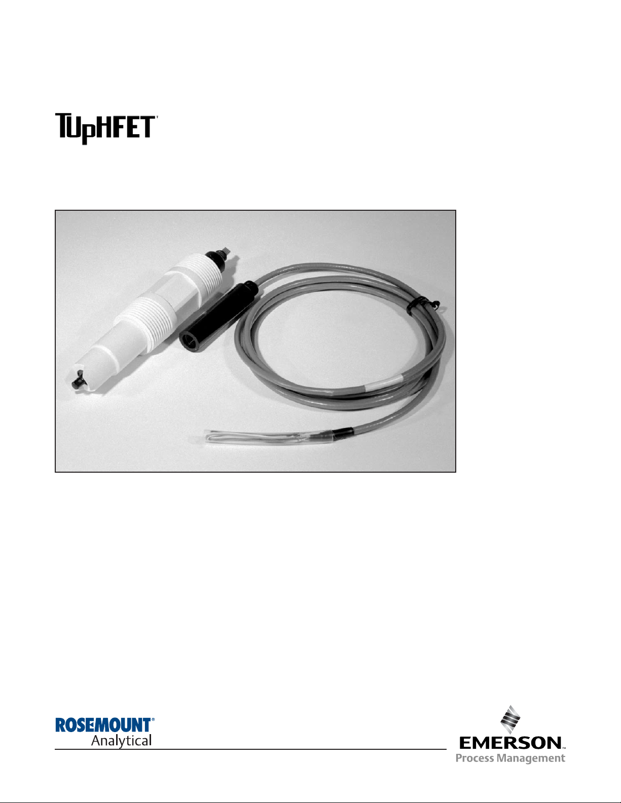
COMBINATION pH SENSOR
Instruction Manual
PN 51-TF396/rev.G
June 2012
MODEL TF396
with mating cable
Model TF396
Page 2

CAUTION
SENSOR/PROCESS
APPLICATION COMPATIBILITY
The wetted sensor materials may not be
compatible with process com position and
operating conditions. Application
compat ibility is entirely the responsibility
of the user.
DANGER
HAZARDOUS AREA
INSTALLATION
This sensor is not Intrinsically Safe. or Explosion
Proof. Installations near flammable liquids or in
hazardous area locations must be carefully evaluated by qualified on site safety personnel.
To secure and maintain an intrinsically safe
installation, an appropriate transmitter/ safety
barrier/sensor combi nation must be used. The
installation system must be in accordance with
the governing approval agency (FM, CSA or
BASEEFA/CENELEC) hazardous area classification requirements. Consult your analyzer/
transmitter instruc tion manual for details.
Proper installation, operation and servicing of
this sensor in a Hazardous Area Instal lation is
entirely the responsibility of the user.
ESSENTIAL INSTRUCTIONS
READ THIS PAGE BEFORE PROCEEDING!
Rosemount Analytical designs, manufactures, and tests its products to meet
many national and international standards. Because these instruments are
sophisticated technical products, you must properly install, use, and maintain
them to ensure they continue to operate within their normal specifications.
The following instructions must be adhered to and integrated into your safety program when installing, using, and maintaining Rosemount Analytical
products. Failure to follow the proper instructions may cause any one of the
following situations to occur: Loss of life; personal injury; property damage;
damage to this instrument; and warranty invalidation.
• Read all instructions prior to installing, operating, and servicing the product. If this Instruction Manual is not the correct manual, telephone 1-800654-7768 and the requested manual will be provided. Save this Instruction
Manual for future reference.
• If you do not understand any of the instructions, contact your Rosemount
representative for clarification.
• Follow all warnings, cautions, and instructions marked on and supplied
with the product.
• Inform and educate your personnel in the proper installation, operation,
and maintenance of the product.
• Install your equipment as specified in the Installation Instructions of the
appropriate Instruction Manual and per applicable local and national
codes. Connect all products to the proper electrical and pressure sources.
• To ensure proper performance, use qualified personnel to install, operate,
update, program, and maintain the product.
• When replacement parts are required, ensure that qualified people use
replacement parts specified by Rosemount. Unauthorized parts and procedures can affect the product’s performance and place the safe operation
of your process at risk. Look alike substitutions may result in fire, electrical hazards, or improper operation.
Emerson Process Management
Rosemount Analytical Inc.
2400 Barranca Parkway
Irvine, CA 92606 USA
Tel: (949) 757-8500
Fax: (949) 474-7250
http://www.raihome.com
© Rosemount Analytical Inc. 2008
About This Document
This manual contains instructions for installation and operation of the Model TF396 TUpHFET
Combination pH Sensor. The following list provides notes concerning all revisions of this document.
Rev. Level Date Notes
A 6/02 This is the initial release of the product manual. The manual has been reformatted to reflect the
Emerson documentation style and updated to reflect any changes in the product offering.
B 4/03 Revised figure 2-3 on page 5.
C 10/05 PN 9330022 has been deleted, changed to PN 9320057 on the drawing of 4TF39603, page 6.
D 2/06 Deleted cable lengths of 8 and 12 ft, changed PN on Figure 2-1, page 4.
E 2/08 Updates of page 1, Description and Specifications and page 2, ordering information.
F 9/09 Updates on 16, DNV logo for 2008.
Page 3

i
MODEL TF396 TABLE OF CONTENTS
MODEL TF396
COMBINATION pH SENSOR
TABLE OF CONTENTS
Section Title Page
1.0 DESCRIPTION AND SPECIFICATIONS................................................................. 1
1.1 Features and Applications........................................................................................ 1
1.2 Specifications........................................................................................................... 1
1.3 Ordering Information ................................................................................................ 2
2.0 INSTALLATION ....................................................................................................... 3
2.1 Unpacking and Inspection........................................................................................ 3
2.2 Mounting .................................................................................................................. 3
3.0 WIRING MODEL TF396 .......................................................................................... 8
4.0 START UP AND CALIBRATION ............................................................................. 11
4.1 Sensor Preparation .................................................................................................. 11
4.2 pH Calibration .......................................................................................................... 11
4.3 Instrument Configuration for use with Model TF396 ................................................ 11
5.0 MAINTENANCE ...................................................................................................... 12
5.1 Automatic Temperature Compensator ..................................................................... 12
5.2 Electrode Cleaning................................................................................................... 12
6.0 RETURN OF MATERIAL......................................................................................... 13
Page 4

MODEL TF396 TABLE OF CONTENTS
LIST OF FIGURES
Number Title Page
2-1 Dimensional Drawing ............................................................................................... 4
2-2 Flow-Through Tee with Adapter................................................................................ 4
2-3 Flow-Through and Insertion Installations ................................................................. 5
2-4 Model TF396 with Insertion Mounting Adapter......................................................... 5
2-5 Submersion Installations .......................................................................................... 6
2-6 Low Flow Cell........................................................................................................... 7
2-7 Jet Spray Cleaner ..................................................................................................... 7
3-1 Wiring to Model 1055 ............................................................................................... 8
3-2 Wiring to Models 3081, 4081, and 5081................................................................... 10
3-3 Wiring to Model 54e ................................................................................................. 10
LIST OF TABLES
Number Title Page
5-1 Ro and R1 Values for Temperature Compensation Elements.................................. 12
5-2 Temperature vs Resistance of Auto T.C. Elements .................................................. 12
ii
Page 5

greater than typical teflon or ceramic junctions) is made of
micron-sized reference pathways allowing for ionic
exchange but preventing plugging by larger particles and will
continue to send a steady pH signal, even in the dirtiest of
applications. The field-proven TUpH reference junction technology results in greatly reduced maintenance requirements.
The TUpH helical reference pathway resists reference poisoning. Ions diffuse through the reference pathways and a
charge is passed to the reference element. The reference
element must be protected from contamination by poisoning
ions such as sulfide, mercury, cyanide, and ammonia that will
cause reference drift and offsets. The TUpH sensor's long
internal reference pathway hinders the contaminants' migration to the reference element thereby providing an increased
sensor life.
All TUpH sensor models have been specifically designed for
improved performance in harsh, dirty, or abrasive applications where large quantities of suspended solids are present.
The Model TF396 offers a watertight sensor-to-cable connector
that prevents cable twisting and eliminates the need for
rewiring when replacing the sensor. The sensor cable
includes an integral preamplifier cap with mating connector
and is compatible with most Rosemount Analytical analyzers
and transmitters.
MODEL TF396 SECTION 1.0
DESCRIPTIONS AND SPECIFICATIONS
SECTION 1.0
DESCRIPTION AND SPECIFICATIONS
1.1 FEATURES AND APPLICATIONS
The ion-selective field effect transistor (ISFET) pH electrode provides a stable pH measurement. Its rate of
response can be ten times faster than glass electrodes,
enabling better process control. Its short response time and
increased stability at low temperatures make it suitable for
use in cold processes like brine or water for cooling. Aging
effects caused by temperature fluctuations or large
changes of process pH are greatly reduced, providing
longer intervals between calibration and maintenance of the
sensor.
Because there is no glass bulb, it can be used in many
applications that restrict or prohibit pH glass electrodes due
to the risk of broken glass getting into the process. It may
also provide longer sensor life in processes that will break
or crack pH glass bulbs. By allowing direct installation into
the process, costs for laboratory analysis of sample lines
are greatly reduced.
The TUpH Reference technology includes a large area
reference junction for minimum maintenance requirements.
The reference junction provides an electrical connection
between the reference electrode and the sample, and helps
maintain a stable reference potential, regardless of the
change in sample pH. The TUpH reference electrode
junction (the entire plastic tip surrounding the ISFET
electrode) maintains a steady reference signal, even in dirty
applications, by resisting plugging (a common cause of pH
signal drift). This large reference junction area (400 times
1.2 SPECIFICATIONS
Measurement Range: 2-12 pH
Measuring element: ISFET
Repeatability: ±0.05 pH
Response time to pH change: 99% in 30 seconds step change
Wetted Materials: Code -01: Polypropylene, EPDM, Ryton, Silicon.
Code -02: 316SST, Titanium, Polypropylene, EPDM, Ryton, Silicon
Process Connections: Code -01: 1 in. MNPT front and rear facing threads
Code -02: 2 in. Tri-Clamp connection
Temperature Range: 0 to 100°C (32 to 212°F) @ 50 psig
Pressure Range: -10 to 100 psig (32 to 790 kPa [abs]) at 50°C
Minimum Process Conductivity: 75 µS/cm; nominal: 100 µS/cm
Cable Lengths: 20 ft, 50 ft (6 m, 18 m)
Weight/Shipping Weight: 0.45 kg/0.9 kg (1 lb/2 lb)
1
Page 6

MODEL TF396 SECTION 1.0
DESCRIPTIONS AND SPECIFICATIONS
The Model TF396 TUpHFET Non-glass ISFET pH Sensor is housed in a molded reinforced polypropylene body
with 1 in. MNPT threads suitable for insertion, submersion or flow through installation, or housed in a 316SST
body for use with a 2.0 inch Tri-Clamp fitting. The sensor includes an ion-selective field effect transistor, a patented
reference junction, a solution ground, and a recessed protective tip. The Model TF396 includes automatic temperature
compensation (Pt 100 RTD) and connector for use with a cable assembly that includes an integral cap with mating
connector and a choice of 20 or 50 ft of cable.
1.3 ORDERING INFORMATION
ACCESSORIES:
FIRST TIME INSTALLATION GUIDE
CODE PREAMPLIFIER/CABLE (Required Selection)
01 Threaded body for insertion/submersion service
02 316 SST Body for use with Tri-clamp (PN 23513-00, ordered separately)
CODE CABLE AND INTEGRAL CAP WITH PREAMPLIFIER
C08 20 ft cable
C50 50 ft cable
TF396 -01 -C08 EXAMPLE
Notes:
1
For first-time installation, cable and integral cap with preamplifier (Codes C20 or C50) must be included.
2
For installations with distances (between the sensor and instrument) of more than 50 ft; a cable extension junction box
should be used.
3
The Model TF396 is compatible with Models 54e, 1055, 81, 3081, 4081, 1056, XMT and 5081 .
MODEL
TF396 NON-GLASS ISFET pH SENSOR
CODE MOUNTING ASSEMBLIES
915240-03 Tee, Flow-through, 2 in. PVC, 3/4 in. NPT
915240-04 Tee, Flow-through, 2 in. PVC, 1 in. NPT
915240-05 Tee, Flow-through, 2 in. PVC, 1-1/2 in. NPT
11275-01 Handrail Mounting Assembly
2002011 Flow Cell, CPVC, 1 in. FNPT
24091-00 Cell, Low Flow
SQP10098-LQD 2.0 inch Tri-Clamp adapter (SQ11109; formerly PN 23513-00)
CODE REMOTE JUNCTION BOXES
23550-00 Cable extension junction box
CODE EXTENSION CABLES (requires a remote junction box)
9200273 Cable, Extension, 11 Conductor, Shielded, Unprepped
23646-01 Cable, Extension, 11 Conductor, Shielded, Prepped, per ft
CODE OTHER
2001492 Tag, Stainless Steel, Specify Marking
12707-00 Jet Spray Cleaner
23242-02 Mounting Adapter, 1-1/2 in. Insertion, 1 in. x 3/4 in.
7901631 Shroud, PVC
9210012 Buffer Solution, 4.01pH, 16 oz.
9210013 Buffer Solution, 6.86pH, 16 oz.
9210014 Buffer Solution, 9.18pH, 16 oz.
9322014 Union, KYNAR
9330022 Union, CPVC
2
Page 7

3
MODEL TF396 SECTION 2.0
INSTALLATION
SECTION 2.0
INSTALLATION
In most cases, the pH sensor can simply be installed
as shipped and readings with an accuracy of ± 0.6 pH
may be obtained. To obtain greater accuracy or to verify proper operation, the sensor must be calibrated as
a loop with its compatible analyzer or transmitter.
2.2.1 Flow Through and Insertion Mounting.
The Model TF396 Sensor has a 1-inch MNPT process
connection at the front of the sensor for mounting into
a 1-1/2 inch tee or the process pipes. See Figure 2-1
through Figure 2-7 for instal lation configurations.
NOTE
LARGE PIPE WRENCHES MUST NOT BE
USED TO TIGHTEN THE SENSOR INTO A
FLANGE OR OTHER TYPE OF MOUNTING.
2.2.2 Submersion Mounting.
The Model TF396 Sensor also has a 1 inch MNPT
process connection at the back of the sensor. Utilizing
a standard 1 inch union, the sensor may be mounted to
a 1 inch SCH 80 CPVC or PVDF standpipe (see Figure
2-5). Tapered pipe threads in plastic tend to loosen after
installation. It is therefore recom mended that Teflon
1
tape be used on the threads and that the tightness of
the connection be checked frequently to assure that no
loosening has occurred. To prevent rain water or condensation from running into the sensor, a weatherproof
junction box is recommended (see Figure 2-5). The
sensor cable must be run through a protective conduit
for isolation from electrical interference or physical
abuse from the process. The sensor should be installed
within 80° of vertical, with the electrode facing down.
The sensor’s cable should not be run with power or
control wiring.
1
Teflon is a registered trademark of E.I. du Pont de Nemours & Co.
2.1 UNPACKING AND INSPECTION.
Inspect the outside of the carton for any damage. If damage is detected, contact the carrier immediately. Inspect
the hardware. Make sure all the items in the packing list
are present and in good condition. Notify the factory if any
part is missing. If the sensor appears to be in satisfactory
condition, proceed to Section 2.2, Mounting.
NOTE
Save the original packing cartons and materials
as most carriers require proof of damage due to
mishandling, etc. Also, if it is necessary to
return the sensor to the factory, you must pack
the sensor in the same manner as it was
received. Refer to Section 6.0 for return instructions. If the sensor is to be stored, the vinyl boot
should be filled with pH buffer solution and
replaced on sensor tip until ready to use.
CAUTION
Buffer solution, in the vinyl boot, may cause
skin or eye irritation.
WARNING
Electrode tip must be wetted at all times (in
storage and in line) to maximize sensor life.
2.2 MOUNTING.
The sensor has been designed to be located in industrial process environments. Temperature and pressure
limitations must not be exceeded at any time. A caution
label regarding this matter is attached to the sensor.
Please do not remove the label. See Figure 2-1.
CAUTION
Internal electrolyte fill solution may cause skin
or eye irritation.
CAUTION
Cable connection at back of sensor body is fragile.
Do not overtighten.
CAUTION
Cable connection at back of sensor body is fragile.
Do not overtighten.
Page 8

4
MODEL TF396 SECTION 2.0
INSTALLATION
FIGURE 2-1. Dimensional Drawing
DWG. NO. REV.
4TF39604 B
MILLIMETER
INCH
FIGURE 2-2. Flow-Through Tee with Adapter (PN 915240-xx*)
MILLIMETER
INCH
xx* Process Connection
Threads
03 3/4 inch
04 1 inch
05 1-1/2 inch
SENSOR CABLE WITH CONNECTOR - NOT SHOWN
Page 9

MODEL TF396 SECTION 2.0
INSTALLATION
DWG. NO. REV.
4TF39601 A
5
FIGURE 2-4. Model TF396 with Insertion Mounting Adapter PN 23242-02
FIGURE 2-3. Flow-Through and Insertion Installations
DWG. NO. REV.
40396P05 C
Page 10

MODEL TF396 SECTION 2.0
INSTALLATION
FIGURE 2-5. Submersion Installations
WHEN INCH AND METRIC DIMS
ARE GIVEN
MILLIMETER
INCH
DWG. NO. REV.
4TF39602 A
DWG. NO. REV.
4TF39603 B
6
PN 23550-00 (WITHOUT PREAMP)
Page 11

7
MODEL TF396 SECTION 2.0
INSTALLATION
FIGURE 2-7. Jet Spray Cleaner PN 12707-00
MILLIMETER
INCH
LOW FLOW CELL PN 24091-00
Inlet and outlet connections are stainless steel and
take 1/4-inch OD tubing. Flow cell is polycarbonate
with 1/4-inch FNPT fittings.
WETTED MATERIALS:
BODY - ACRYLIC
NUT - CPVC
FITTINGS - 316 SST
SEALS - BUNA N
FLOW CELL RATINGS
TEMPERATURE: 32-122F (50C)
MAX. PRESSURE: 65 PSIG (549 kPa [abs])
FLOW RATE: 2-5 GPH (7.6-18.9 LPH)
The see-through acrylic Low Flow Cell
Page 12

8
Wiring. The Model TF396 has a mating cable with
built-in preamplifier and is offered with a shielded
cable. The cable should be handled carefully and kept
dry and free of corrosive chemicals at all times.
Extreme care should be used to prevent it from being
twisted, damaged or scraped by rough, sharp edges or
surfaces. Please refer to Figures 3-1 through 3-3 for
wiring Model TF396.
DANGER
DO NOT CONNECT SENSOR CABLE TO
POWER LINES. SERIOUS INJURY MAY
RESULT.
Figures in this section provide the guidelines for wiring the TF396 sensor to various analyzers/transmitters.
To determine which wiring guideline to use, locate the model number of the analyzer/transmitter to be installed.
1. If the cable needs to be extended (maximum distance from sensor to analyzer is 250 ft), use a high quality
eleven conductor double shielded instrument cable available from Rosemount Analytical.
NOTE
If the cable is too long, loop up the excess cable. If the cable has to be shortened, cut and terminate each
conductor neatly and make sure that the overall (outermost) drain wire is not shorted out with either
of the two inner drain wires (shields).
2. Signal cable should be run in a dedicated conduit (preferably an earth grounded metallic conduit) and should
be kept away from AC power lines. For your convenience, a wire nut kit is furnished (in a plastic bag wrapped
around the cable).
NOTE
For maximum EMI/RFI protection when wiring from the sensor to the junction box, the outer braid of the
sensor should be connected to the outer braided shield of the extension cable. The outer braid of the
extension cable to the instrument must be terminated at earth ground or by using an appropriate metal
cable gland fitting that provides a secure connection to the instrument cable.
MODEL TF396 SECTION 3.0
WIRING - MODEL TF396
SECTION 3.0
WIRING — MODEL TF396
Page 13

9
MODEL TF396 SECTION 3.0
WIRING - MODEL TF396
FIGURE 3-1. Wiring to Model 1055.
DWG. NO. REV.
14055103 B
DWG. NO. REV.
41055102 B
Page 14

10
MODEL TF396 SECTION 3.0
WIRING - MODEL TF396
FIGURE 3-2. Wiring to Model 54e.
DWG. NO. REV.
40054E04 A
FIGURE 3-2. Wiring to Models 3081, 4081, & 5081.
DWG. NO. REV.
40508114 A
Page 15

Recommended pH Sensor Standardization:
For maximum accuracy, the sensor can be standardized
online or with a process grab sample after a buffer calibration has been performed and the sensor has been conditioned to the process. Standardization accounts for the
sensor junction potential and other interferences.
Standardization will not change the sensor’s slope but will
simply adjust the analyzer’s reading to match that of the
known process pH.
1. While obtaining a process solution sample (it is recommended that the sample is taken close to the sensor),
record the pH value that is shown on the
analyzer/transmitter display.
2. Measure and record the pH of the process solution
sample with another temperature compensated, calibrated pH instrument. For best results, standardization
should be performed at the process temperature.
3. Adjust the analyzer/transmitter value to the standardized value.
4.3 INSTRUMENT CONFIGURATION FOR
USE WITH MODEL TF396
INSTRUMENT CONFIGURATION REQUIREMENTS: For
proper operation, instruments capable of advanced sensor
diagnostics must have this feature turned off (please refer
to the appropriate instrument's instruction manual for complete instructions) .
MODEL 54epH/ORP: From the Program menu, select
Configure, then Diagnostics. Edit diagnostics and select
off.
SOLU COMP II MODEL 1055: From the Program menu,
select Measurement, then Sensor1 or Sensor2 as appropriate, then pH. At the screen prompt Glass Fault
Enable?, select No.
MODELS 81, 3081, 4081 OR 5081: From the Program
menu, select dIAG and toggle to OFF.
MODEL TF396 SECTION 4.0
START UP AND CALIBRATION
SECTION 4.0
START UP AND CALIBRATION
4.1 SENSOR PREPARATION.
In most cases, the pH sensor can simply be installed as shipped
and readings with an accuracy of ± 0.6 pH may be obtained. To
obtain greater accuracy or to verify proper operation, the sensor
must be calibrated as a loop with its compatible analyzer or
transmitter.
4.2 pH CALIBRATION.
After a temporary connection is established between the
sensor and the instrument, a buffer calibration may be performed. Consult appropriate pH analyzer or transmitter
instruction manual for specific calibration and standardization procedures, or see below for recommended two-point
buffer calibration procedure.
Recommended two-point buffer calibration procedure:
Select two stable buffer solutions, preferably pH 4.0 and
10.0 (pH buffers other than pH 4.0 and pH 10.0 can be
used as long as the pH values are at least two pH units
apart).
NOTE
A pH 7.0 buffer solution reads a mV value of approximately zero, and pH buffers read approximately 59.1
mV for each pH unit above or below pH 7.0. Check
the pH buffer manufacturer specifications for millivolt
values at various temperatures since it may affect the
actual value of the buffer solution mV/pH value.
1. Immerse sensor in the first buffer solution. Allow sensor to adjust to the buffer temperature (to avoid errors
due to temperature differences between the buffer
solution and sensor temperature) and wait for reading
to stabilize. Value of buffer can now be acknowledged
by analyzer/transmitter.
2. Once the first buffer has been acknowledged by the
analyzer/transmitter, rinse the buffer solution off of the
sensor with distilled or deionized water.
3. Repeat steps 1 and 2 using the second buffer solution.
4. Once the analyzer/transmitter has acknowledged both
buffer solutions, a sensor slope (mV/pH) is established
(the slope value can be found within the analyzer/
transmitter).
11
Page 16

12
MODEL TF396 SECTION 5.0
MAINTENANCE
The Model TF396 Sensors require minimum maintenance. The sensor should be kept clean and free of
debris and sediment at all times. The frequency of
cleaning by wiping or brushing with a soft cloth or
brush is determined by the nature of the solution being
measured. The sensor should be removed from the
process periodically and checked in buffer solutions.
If the sensor will not calibrate, refer to your analyzer/
transmitter instruction manual for proper test procedures. If it is determined that the sensor has failed, it
should be discarded and replaced.
5.1 AUTOMATIC TEMPERATURE
COMPENSATOR.
The temperature compensator element is temp erature sensitive and can be checked with an ohmmeter. Resistance increases with temperature.
The Pt100 will read 110 ohms at 25°C. Resistance
varies with temperature for a Pt100 element and can
be determined according to Table 5-2 or the following
formula:
RT=Ro[l+R1(T-20)]
Where RT = Resistance
T = Temperature in °C
Refer to Table 5-1 for Roand
R
1
values.
5.2 ELECTRODE CLEANING
If the electrode is coated or dirty, clean as follows:
1. Remove the sensor from process.
2. Wipe the ISFET silicon surface with a soft, clean,
lint free cloth or tissue. If this does not remove the
dirt or coating, go to Step 3. (Detergents clean oil
and grease; acids remove scale.)
3. Wash the sensor tip in a mild detergent solution
and rinse it in clean water. If this does not clean
the ISFET, go to Step 4.
SECTION 5.0
MAINTENANCE
4. Wash the sensor tip in a dilute 5% hydro chloric
acid solution and rinse with clean water. Soaking
the sensor overnight in the acid solution can
improve cleaning action.
NOTE
Erroneous pH results may result immedi ately after acid soak, due to reference
junction potential build-up.
Replace the sensor if cleaning does not
restore sensor operation.
Resistance
Temperature °C (Ohms) ±1%
Pt100
0 100.0
10 103.8
20 107.7
25 109.6
30 111.5
40 115.4
50 119.2
60 123.1
70 126.9
80 130.8
90 134.6
100 138.5
Temperature
Compensation Element
R
o
R
1
Pt100 107.7 .00385
TABLE 5-2. Temperature vs. Resistance of Auto
T.C. Elements
WARNING
BEFORE REMOVING THE SENSOR,
be absolutely certain that the
process pressure is reduced to 0
psig and the process temperature is
lowered to a safe level!
CAUTION
The solution used during the following check is an
acid and should be handled with care. Follow the
directions of the acid manufacturer. Wear the proper
protective equipment. Do not let the solution come in
contact with skin or clothing. If contact with skin is
made, immediately rinse with clean water.
TABLE 5-1. Roand R1Values for Temperature
Compensation Elements
Page 17

13
MODEL TF396 SECTION 6.0
RETURN OF MATERIAL
SECTION 6.0
RETURN OF MATERIAL
6.1 GENERAL.
To expedite the repair and return of instruments, proper communication between the customer and the factory is important. Before returning a product for
repair, call 1-949-757-8500 for a Return Materials
Authorization (RMA) number.
6.2 WARRANTY REPAIR.
The following is the procedure for returning instruments still under warranty:
1. Call Rosemount Analytical for authorization.
2. To verify warranty, supply the factory sales order
number or the original purchase order number.
In the case of individual parts or sub-assemblies,
the serial number on the unit must be supplied.
3. Carefully package the materials and enclose
your “Letter of Transmittal” (see Warranty). If
possible, pack the materials in the same manner
as they were received.
4. Send the package prepaid to:
Rosemount Analytical Inc., Uniloc Division
Uniloc Division
2400 Barranca Parkway
Irvine, CA 92606
Attn: Factory Repair
RMA No. ____________
Mark the package: Returned for Repair
Model No. ____
6.3 NON-WARRANTY REPAIR.
The following is the procedure for returning for repair
instruments that are no longer under warranty:
1. Call Rosemount Analytical for authorization.
2. Supply the purchase order number, and make
sure to provide the name and telephone number
of the individual to be contacted should additional information be needed.
3. Do Steps 3 and 4 of Section 6.2.
NOTE
Consult the factory for additional information regarding service or repair.
Page 18

FROM: RETURN BILL TO:
_____________________________ _____________________________ _____________________________
_____________________________ _____________________________ _____________________________
_____________________________ _____________________________ _____________________________
CUSTOMER/USER MUST SUBMIT MATERIAL SAFETY SHEET (MSDS) OR COMPLETE STREAM COMPOSITION, AND/OR
LETTER CERTIFYING THE MATERIALS HAVE BEEN DISINFECTED AND/OR DETOXIFIED WHEN RETURNING ANY PRODUCT, SAMPLE OR MATERIAL THAT HAVE BEEN EXPOSED TO OR USED IN AN ENVIRONMENT OR PROCESS THAT CONTAINS A HAZARDOUS MATERIAL ANY OF THE ABOVE THAT IS SUBMITTED TO ROSEMOUNT ANALYTICAL WITHOUT
THE MSDS WILL BE RETURNED TO SENDER C.O.D. FOR THE SAFETY AND HEALTH OF OUR EMPLOYEES. WE THANK
YOU IN ADVANCE FOR COMPLIANCE TO THIS SUBJECT.
SENSOR OR CIRCUIT BOARD ONLY:
(Please reference where from in MODEL / SER. NO. Column)
1. PART NO.__________________________1. MODEL_________________________________1. SER. NO. ________________
2. PART NO.__________________________2. MODEL_________________________________2. SER. NO. ________________
3. PART NO.__________________________3. MODEL_________________________________3. SER. NO. ________________
4. PART NO.__________________________4. MODEL_________________________________4. SER. NO. ________________
PLEASE CHECK ONE:
nn REPAIR AND CALIBRATE nn DEMO EQUIPMENT NO. __________________________
nn EVALUATION nn OTHER (EXPLAIN) _______________________________
nn REPLACEMENT REQUIRED? nn YES nn NO _________________________________________________
DESCRIPTION OF MALFUNCTION:
______________________________________________________________________________________________________
______________________________________________________________________________________________________
______________________________________________________________________________________________________
WARRANTY REPAIR REQUESTED:
nn YES-REFERENCE ORIGINAL ROSEMOUNT ANALYTICAL ORDER NO. ________________________________________
CUSTOMER PURCHASE ORDER NO. _________________________________________________
nn NO-PROCEED WITH REPAIRS-INVOICE AGAINST P.O. NO. _________________________________________________
nn NO-CONTACT WITH ESTIMATE OF REPAIR CHARGES: LETTER nn __________________________________________
PHONE
nn ___________________________________________
NAME ____________________________________________________ PHONE _________________________________________
ADDRESS ___________________________________________________________________________________________________
______________________________________________________________ ZIP _________________________________________
RETURN AUTHORITY FOR CREDIT ADJUSTMENT [Please check appropriate box(s)]
nn WRONG PART RECEIVED nn REPLACEMENT RECEIVED
nn DUPLICATE SHIPMENT REFERENCE ROSEMOUNT ANALYTICAL SALES ORDER NO.__________
nn RETURN FOR CREDIT RETURN AUTHORIZED BY: ______________________________________
WARRANTY DEFECT____________________________________________________________________________________
_____________________________________________________________________________________________________
24-6047
RETURN OF MATERIALS REQUEST
•IMPORTANT!
This form must be completed to ensure expedient factory service.
R
E
P
A
I
R
S
T
A
T
U
S
R
E
A
S
O
N
F
O
R
R
E
T
U
R
N
C
U
S
T
O
M
E
R
N
O
T
I
C
E
T
O
S
E
N
D
E
R
Emerson Process Management
Rosemount Analytical Inc.
2400 Barranca Parkway
Irvine, CA 92606 USA
Tel: (949) 757-8500
Fax: (949) 474-7250
http://www.raihome.com
© Rosemount Analytical Inc. 2008
Page 19

WARRANTY
Seller warrants that the firmware will execute the programming instructions provided by Seller, and that the Goods manufactured
or Services provided by Seller will be free from defects in materials or workmanship under normal use and care until the expiration of the applicable warranty period. Goods are warranted for twelve (12) months from the date of initial installation or eighteen
(18) months from the date of shipment by Seller, whichever period expires first. Consumables, such as glass electrodes,
membranes, liquid junctions, electrolyte, o-rings, catalytic beads, etc., and Services are warranted for a period of 90
days from the date of shipment or provision.
Products purchased by Seller from a third party for resale to Buyer ("Resale Products") shall carry only the warranty extended by
the original manufacturer. Buyer agrees that Seller has no liability for Resale Products beyond making a reasonable commercial
effort to arrange for procurement and shipping of the Resale Products.
If Buyer discovers any warranty defects and notifies Seller thereof in writing during the applicable warranty period, Seller shall, at
its option, promptly correct any errors that are found by Seller in the firmware or Services, or repair or replace F.O.B. point of manufacture that portion of the Goods or firmware found by Seller to be defective, or refund the purchase price of the defective portion of the Goods/Services.
All replacements or repairs necessitated by inadequate maintenance, normal wear and usage, unsuitable power sources, unsuitable environmental conditions, accident, misuse, improper installation, modification, repair, storage or handling, or any other
cause not the fault of Seller are not covered by this limited warranty, and shall be at Buyer's expense. Seller shall not be obligated to pay any costs or charges incurred by Buyer or any other party except as may be agreed upon in writing in advance by
an authorized Seller representative. All costs of dismantling, reinstallation and freight and the time and expenses of Seller's personnel for site travel and diagnosis under this warranty clause shall be borne by Buyer unless accepted in writing by Seller.
Goods repaired and parts replaced during the warranty period shall be in warranty for the remainder of the original warranty period or ninety (90) days, whichever is longer. This limited warranty is the only warranty made by Seller and can be amended only
in a writing signed by an authorized representative of Seller. Except as otherwise expressly provided in the Agreement, THERE
ARE NO REPRESENTATIONS OR WARRANTIES OF ANY KIND, EXPRESS OR IMPLIED, AS TO MERCHANTABILITY, FITNESS FOR PARTICULAR PURPOSE, OR ANY OTHER MATTER WITH RESPECT TO ANY OF THE GOODS OR SERVICES.
RETURN OF MATERIAL
Material returned for repair, whether in or out of warranty, should be shipped prepaid to:
Emerson Process Management
Liquid Division
2400 Barranca Parkway
Irvine, CA 92606
The shipping container should be marked:
Return for Repair
Model
_______________________________
The returned material should be accompanied by a letter of transmittal which should include the following information (make a
copy of the "Return of Materials Request" found on the last page of the Manual and provide the following thereon):
1. Location type of service, and length of time of service of the device.
2. Description of the faulty operation of the device and the circumstances of the failure.
3. Name and telephone number of the person to contact if there are questions about the returned material.
4. Statement as to whether warranty or non-warranty service is requested.
5. Complete shipping instructions for return of the material.
Adherence to these procedures will expedite handling of the returned material and will prevent unnecessary additional charges
for inspection and testing to determine the problem with the device.
If the material is returned for out-of-warranty repairs, a purchase order for repairs should be enclosed.
Page 20

Credit Cards for U.S. Purchases Only.
The right people,
the right answers,
right now.
ON-LINE ORDERING NOW AVAILABLE ON OUR WEB SITE
http://www.rosemountanalytical.com
Specifications subject to change without notice.
Emerson Process Management
2400 Barranca Parkway
Irvine, CA 92606 USA
Tel: (949) 757-8500
Fax: (949) 474-7250
http://www.rosemountanalytical.com
© Rosemount Analytical Inc. 2012
8
 Loading...