

Page 1

Rosemount™ TCL
Total Chlorine System with Rosemount 56 Transmitter
Manual
LIQ-MAN-TCL-56, Rev B
July 2017
Page 2

Essential instructions
Read this page before proceeding!
Rosemount designs, manufactures, and tests its products to meet many national and international standards. Because these
instruments are sophisticated technical products, you must properly install, use, and maintain them to ensure they continue to
operate within their normal specifications. The following instructions must be adhered to and integrated into your safety program
when installing, using, and maintaining Rosemount products. Failure to follow the proper instructions may cause any one of the
following situations to occur: loss of life, personal injury, property damage, damage to this instrument, and warranty invalidation.
• Read all instructions prior to installing, operating, and servicing the product. If this Instruction Manual is not the correct
manual, call 1 800 999 9307, and Rosemount will provide the requested manual. Save this Instruction Manual for future
reference.
• If you do not understand any of the instructions, contact your Rosemount representative for clarification.
• Follow all warnings, cautions, and instructions marked on and supplied with the product.
• Inform and educate your personnel in the proper installation, operation, and maintenance of the product.
• Install your equipment as specified in the installation instructions of this manual and per applicable local and national codes.
Connect all products to the proper electrical and pressure sources.
• To ensure proper performance, use qualified personnel to install, operate, update, program, and maintain the product.
• When replacement parts are required, ensure that qualified people use replacement parts specified by Rosemount.
Unauthorized parts and procedures can affect the product's performance and place the safe operation of your product at
risk. Look alike substitutions may result in fire, electrical hazards, or improper operation.
• Ensure that all equipment doors are closed and protective covers are in place, except when maintenance is being performed
by qualified people, to prevent electrical shock and personal injury.
DANGER!
HAZARDOUS AREA INSTALLATION
Installations near flammable liquids or in hazardous area locations must be carefully evaluated by qualified on site safety personnel.
This device is not intrinsically safe or explosion proof.
To secure and maintain an intrinsically safe installation, the certified safety barrier, transmitter, and sensor combination must be
used. The installaiton system must comply with the governing approval agency (FM, CSA, or BASEEFA/CENELEC) hazardous area
classification requirements. Consult your transmitter instruction manual for details.
Proper installation, operation, and servicing of this device in a hazardous area installation is entirely your responsibility.
WARNING!
ELECTRICAL SHOCK HAZARD
Making cable connections to and servicing this instrument require access to shock hazard level voltages which can cause death or
serious injury.
Be sure to disconnect all hazardous voltage before opening the enclosure.
Relay contacts made to separate power sources must be disconnected before servicing.
Electrical installation must be in accordance with the National Electrical Code (ANSI/NFPA-70) and/or any other applicable national
or local codes.
Unused cable conduit entries must be securely sealed by non-flammable closures to provide enclosure integrity in compliance with
personal safety and environmental protection requirements.
The unused conduit openings need to be sealed with NEMA 4X or IP65 conduit plugs to maintain the ingress protection rating (IP65).
For safety and proper performance, this instrument must be connected to a properly grounded three-wire power source.
Proper relay use and configuration is your responsibility.
No external to the instrument of more than 69 Vdc or 43 V peak allowed with the exception of power and relay terminals. Any
violation will impair the safety protection provided.
Do not operate this instrument without the front cover secured. Refer installation, operation, and servicing to qualified personnel.
Page 3

WARNING!
This product is not intended for use in the light industrial, residential, or commercial environment, per the instrument's certification
to EN50081-2.
WARNING!
HAZARDOUS VOLTAGE
Can cause severe injury or death. Disconnect power before servicing.
CAUTION!
SENSOR/PROCESS APPLICATION COMPATIBILITY
Wetted materials may not be compatible with process composition and operating conditions. Application compatibility is entirely
your responsibility.
About this document
This manual contains instructions for installation and operation of the Model TCL56 Total
Chlorine Transmitter.
The following list provides notes concerning all revisions of this document.
Rev. level Date Notes
A 5/11 This is the initial release of the product manual. This manual has been refor-
matted to reflect the Emerson documentation style and updated to reflect
any change in the product offering.
B 7/17 All instances of analyzer have been replaced with transmitter. The manual has
been reformatted to reflect new Emerson branding guidelines.
Page 4

Page 5

Contents
Contents
Chapter 1 Description and Specifications ........................................................................................1
1.1 Features .......................................................................................................................................1
1.2 Specifications ...............................................................................................................................2
1.3 Ordering information and accessories ..........................................................................................5
Chapter 2 Principles of operation ................................................................................................... 9
Chapter 3 Installation ...................................................................................................................11
3.1 Unpacking and inspection ..........................................................................................................11
3.2 Installation .................................................................................................................................11
3.2.1 General information ....................................................................................................11
3.2.2 Install the sample conditioning enclosure ....................................................................11
3.2.3 Install the sensor ......................................................................................................... 14
Chapter 4 Wiring ..........................................................................................................................17
4.1 Prepare transmitter conduit openings ........................................................................................17
4.2 Provide power to the sample conditioning system .....................................................................17
4.3 Make power, alarm, output, and sensor connections in the transmitter ..................................... 18
4.3.1 Power ..........................................................................................................................18
4.3.2 Analog output wiring .................................................................................................. 19
4.3.3 Alarm wiring ................................................................................................................20
4.4 Sensor wiring ............................................................................................................................. 21
4.5 Apply power to the transmitter and complete Quick Start ......................................................... 22
Chapter 5 Startup .........................................................................................................................25
5.1 Prepare the reagent ................................................................................................................... 25
5.2 Zero the sensor .......................................................................................................................... 26
5.3 Start sample flow ....................................................................................................................... 26
5.4 Begin operation and calibrate the sensor ................................................................................... 26
Chapter 6 Display and operation .................................................................................................. 27
6.1 Main display ...............................................................................................................................27
6.2 Keypad .......................................................................................................................................28
6.3 Operation .................................................................................................................................. 28
6.4 Hold ...........................................................................................................................................31
6.4.1 Purpose .......................................................................................................................31
6.4.2 Using the Hold function ...............................................................................................31
6.5 Main display ...............................................................................................................................33
6.5.1 Configuring the main display .......................................................................................33
6.5.2 Setting brightness .......................................................................................................34
6.6 Security ......................................................................................................................................34
6.6.1 How the security code works .......................................................................................34
6.6.2 Assigning security codes ............................................................................................. 35
6.6.3 Bypassing security codes .............................................................................................35
Chapter 7 Programming the transmitter ...................................................................................... 37
7.1 Entering the Program menus ..................................................................................................... 37
7.2 Outputs ..................................................................................................................................... 38
7.2.1 Menu tree ....................................................................................................................38
7.2.2 Settings .......................................................................................................................38
Manual i
Page 6

Contents
7.3 Relays ........................................................................................................................................ 38
7.3.1 Menu tree ....................................................................................................................38
7.3.2 Settings .......................................................................................................................39
7.4 Measurement ............................................................................................................................ 40
7.4.1 Menu tree ....................................................................................................................40
7.4.2 Settings .......................................................................................................................41
7.5 Temperature ..............................................................................................................................41
7.5.1 Menu tree ....................................................................................................................41
7.5.2 Settings .......................................................................................................................41
7.6 Security ......................................................................................................................................42
7.6.1 Menu tree ....................................................................................................................42
7.6.2 Settings .......................................................................................................................42
7.6.3 Restoring default settings ........................................................................................... 42
Chapter 8 Calibration ................................................................................................................... 43
8.1 Introduction ...............................................................................................................................43
8.2 Entering the Calibration menus ..................................................................................................43
8.3 Calibrating temperature ............................................................................................................ 44
8.4 Calibrating the free chlorine sensor ............................................................................................44
8.5 Calibrating the analog outputs ...................................................................................................45
8.6 Reset ..........................................................................................................................................45
8.6.1 Purpose .......................................................................................................................45
8.6.2 Procedure ....................................................................................................................46
Chapter 9 Data and event logging and retrieval ............................................................................47
9.1 Overview ................................................................................................................................... 47
9.2 Configuration ............................................................................................................................ 47
9.3 Downloading data and events ....................................................................................................48
9.4 Date and time ............................................................................................................................ 48
Chapter 10 Graphical display ..........................................................................................................49
10.1 Overview ................................................................................................................................... 49
10.2 Configuration ............................................................................................................................ 49
Chapter 11 Digital communications ............................................................................................... 51
Chapter 12 Maintenance ................................................................................................................ 53
12.1 Transmitter ................................................................................................................................53
12.2 Total chlorine sensor ..................................................................................................................54
12.2.1 General ....................................................................................................................... 54
12.2.2 Cleaning the membrane ..............................................................................................55
12.2.3 Replacing the membrane ............................................................................................ 55
12.2.4 Replacing the electrolyte solution and membrane .......................................................55
12.3 Sample conditioning system ......................................................................................................57
12.3.1 Reagent .......................................................................................................................57
12.3.2 Sample and reagent tubing ......................................................................................... 57
12.3.3 Replacing sample tubing .............................................................................................58
12.3.4 Peristaltic pump tubing ...............................................................................................60
12.3.5 Replacing the air pump ............................................................................................... 63
12.3.6 Replacing the air pump diaphragm and check valves ...................................................65
Chapter 13 Troubleshooting .......................................................................................................... 69
13.1 Overview ................................................................................................................................... 69
13.2 Reading and troubleshooting Fault and Warning messages ....................................................... 69
13.3 Sensor diagnostics ..................................................................................................................... 70
ii Rosemount TCL
Page 7

Contents
13.4 Troubleshooting calibration problems ....................................................................................... 70
13.5 Other troubleshooting ...............................................................................................................71
13.5.1 Readings are low. ........................................................................................................ 71
13.5.2 Process readings are erratic or wander. ....................................................................... 73
13.5.3 Readings drift. ............................................................................................................. 74
13.5.4 Readings are too high ..................................................................................................74
13.6 Other troubleshooting - general ................................................................................................ 74
13.6.1 Current is output too low. ........................................................................................... 74
13.6.2 Alarm relays do not operate properly. ......................................................................... 74
13.7 Simulating inputs - chlorine ....................................................................................................... 75
13.8 Simulating inputs - temperature ................................................................................................ 75
13.8.1 General ....................................................................................................................... 75
13.8.2 Simulating temperature .............................................................................................. 76
Chapter 14 Return of material ........................................................................................................ 79
Manual iii
Page 8

Contents
iv Rosemount TCL
Page 9

Description and Specifications
1 Description and Specifications
1.1 Features
Rosemount TCL Sample Conditioning System
The sample conditioning system permits a single sensor to measure total chlorine in water.
The sample conditioning system continuously injects a solution of acetic acid (vinegar) and
potassium iodide into the sample. The acid lowers the pH to between 3.5 and 4.5 and
allows total chlorine in the sample to quantitatively react with the potassium iodide to
produce iodine. The sensor measures the iodine concentration, and the transmitter
displays the total oxidant concentration in ppm as Cl2.
Rosemount 56 Transmitter
The Rosemount 56 Transmitter measures total chlorine when used with the TCL and
499ACL-02 sensor.
The transmitter is housed in a corrosion resistant NEMA 4X enclosure. It is suitable for
panel, pipe, or wall mounting. The large, high resolution, full color display shows total
chlorine concentration and temperature in 0.5 in. (13 mm) high characters. Six other userselectable variables can be shown in smaller characters. Operation of the transmitter is
through the membrane keypad.
Menu screens for calibration and programming screens are simple and intuitive. Plain
language prompts in nine languages guide you. Information about program settings and
calibration, as well as troubleshooting guidance, is available on-screen at the press of a
button.
The transmitter has four fully programmable analog outputs, with HART digital
communication superimposed on output 1. Profibus DP digital communication is available
as an option. PID control is standard.
Four fully programmable relays are available. Relays can be configured as simple high/low
setpoint alarms or can be used to perform a number of timer functions as well as time
proportional control (TPC). For more information about relay actions, refer to the
Rosemount 56 Product Data Sheet.
A data and event logger are standard. The data logger stores up to 30 days of data, and the
event logger stores up to 300 events. Events can be viewed on screen, and data can be
shown in a full color dual graphics display. Data and events can also be downloaded
through a USB port on the front panel of the transmitter.
Rosemount 499ACL-02 Total Chlorine Sensor
The Rosemount 499ACL-02 Total Chlorine Sensor is used in the TCL sample conditioning
system. Although the sensor is called a chlorine sensor, it really measures iodine. The
iodine comes from the reaction between oxidants in the sample and the acetic acid/
potassium iodide reagent added by the sample conditioning system.
Manual 1
Page 10
Description and Specifications
The sensor consists of a gold cathode and a silver anode in an electrolyte solution. A
silicone membrane, permeable to iodine, is stretched over the cathode. The transmitter
applies a voltage to the cathode sufficiently negative to reduce all the iodine reaching it.
Because the concentration of iodine in the sensor is always zero, a concentration gradient
continuously forces iodine from the sample through the membrane into the sensor.
The reduction of iodine in the sensor generates a current directly proportional to the
diffusion rate of iodine through the membrane, which is directly proportional to the
concentration of iodine in the sample. Because the iodine concentration depends on the
amount of total chlorine in the sample, the sensor current is ultimately proportional to the
total chlorine concentration.
The permeability of the membrane to iodine is a function of temperature. A Pt100 RTD in
the sensor measures the temperature, and the transmitter uses the temperature to
compensate the total chlorine reading for changes in membrane permeability.
Sensor maintenance is fast and easy. Replacing the membrane requires no special tools or
fixtures. Simply place the membrane assembly on the cathode and screw the retainer in
place. Installing a new membrane and replenishing the electrolyte takes only a few
minutes.
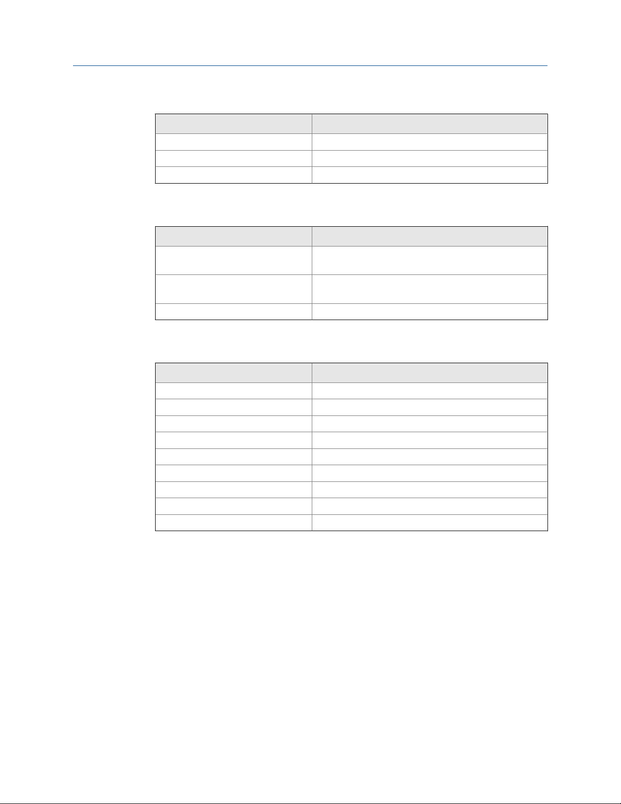
1.2 Specifications
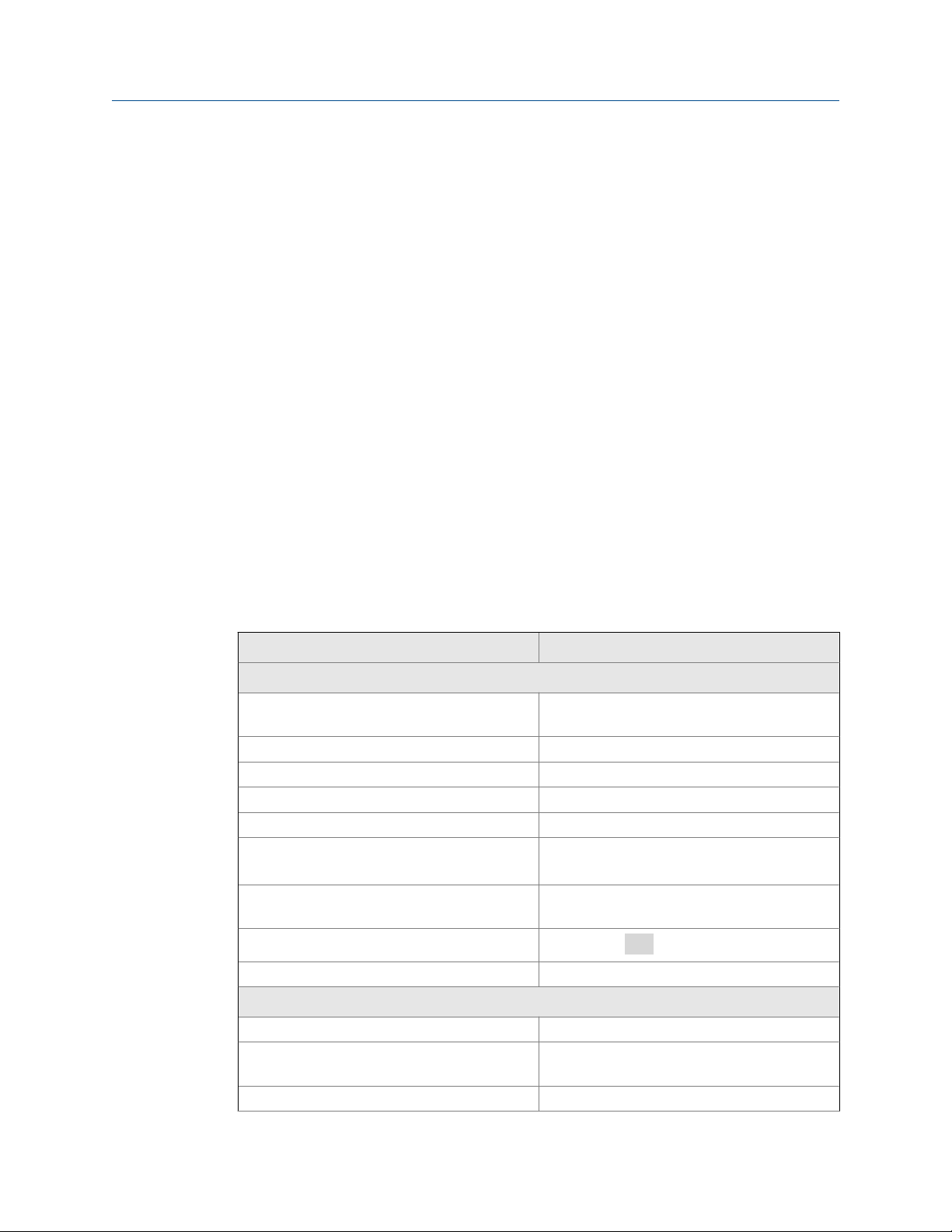
Sample Conditioning SystemTable 1-1:
Physical characteristics Specifications
General
Enclosure Fiberglass reinforced polyester, NEMA 3 (IP53)
Dimensions 14.5 x 13.0 x 8.6 in. (369 x 329 x 218 mm)
Mounting Wall
Ambient temperature 0 to 50 °C (32 to122 °F)
Ambient humidity 0 to 90% (non-condensing)
Power 115 Vac, 6.9 W, 50/60 Hz
Hazardous location The TCL Sample Conditioning System has no
Pumps
Weight/shipping weight 14 lb/16 lb (6.5 kg/7.5 kg)
Sample requirements
Inlet connection Compression fitting, accepts 1/4 in. OD tubing
Drain connection 3/4 in. barbed fitting (must drain to open at-
Inlet pressure <100 psig (791 kPa abs)
suitable for marine environments
230 Vac, 7.0 W, 50/60 Hz
hazardous location approvals.
EN 809:1998
mosphere)
2 Rosemount TCL
Page 11
Description and Specifications
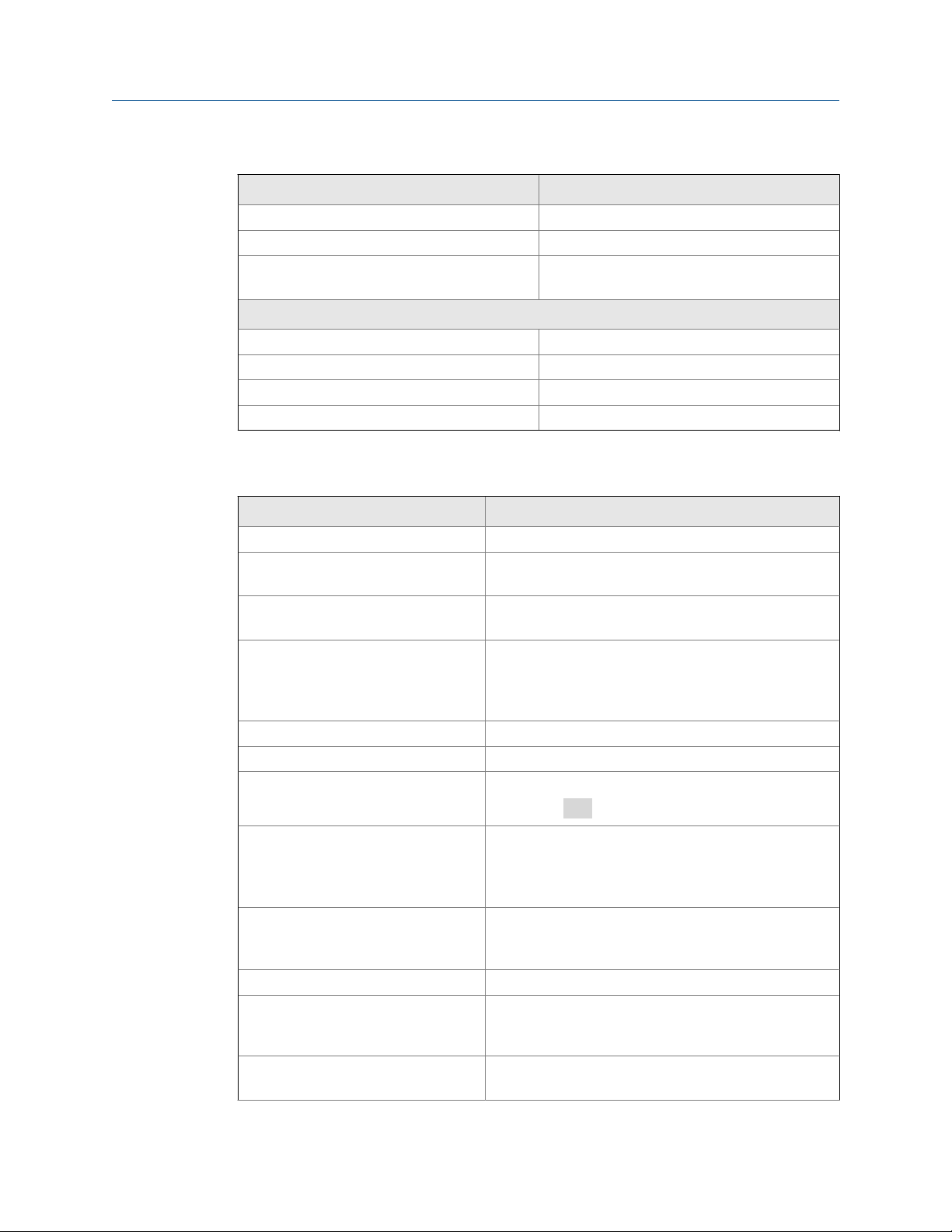
Sample Conditioning System (continued)Table 1-1:
Physical characteristics Specifications
Flow At least 0.25 gph (15 mL/min)
Temperature 0 to 50 °C (32 to122 °F)
Total alkalinity <300 mg/L as CaCO3. For samples containing
<50 mg/L alkalinity, consult the factory.
Sample conditioning system
Reagent Potassium iodide in vinegar
Reagent usage 5 gallons last approximately 60 days.
Reagent pump Fixed speed peristaltic pump, about 0.2 mL/min
Sample pump Fixed speed peristaltic pump, about 11 mL/min
Rosemount 56 TransmitterTable 1-2:
Physical characteristics Specifications
Case Polycarbonate
Display Full color LCD, 3.75 x 2.20 in. (95 x 56 mm); you can cus-
tomaize the display.
Languages English, French, German, Italian, Spanish, Portuguese,
Chinese, Russian, and Polish
Ambient temperature and humidity -10 to 60 °C (14 to 140 °F); relative humidity 5 to 95%
(non-condensing). Between -5 and 55 °C (23 and 131 °F)
there is no visible degradation in display response or performance.
Storage temperature -20 to 60 °C (-4 to 140 °F)
Power 85 to 265 Vac, 47.5 to 65.0 Hz, 20 W
RFI/EMI
LVD
Outputs Four 4-20 or 0-20 mA isolated current outputs; assigna-
Alarms and timers Four relays, fully configurable as a setpoint alarm, inter-
Relays Form C, SPDT, epoxy sealed
Relay contact ratings
Control features PID control (analog output) and time proportional con-
EN-61326
EN-6101-01
ble to measurement or temperature; fully scalable; maximum load 550 Ω. HART digital signal is superimposed on
output 1.
val timer, TPC, bleed and feed timer, delay timer, date
and time timer, and fault alarm.
5 A at 28 Vdc or 300 Vac (resistive)
1/8 HP at 120/240 Vac
trol or TPC (relays) are standard.
Manual 3
Page 12
Description and Specifications
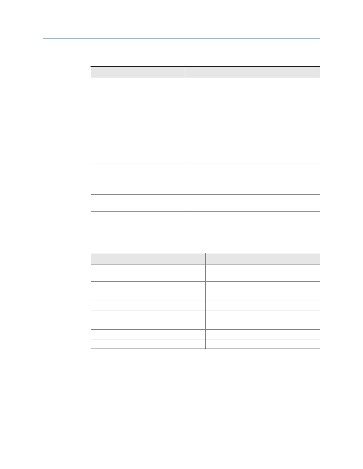
Physical characteristics Specifications
Data logger Data automatically stored every 30 seconds for 20 days;
Event logger Stores up to 300 events with date and time stamps:
Data and event downloading Through USB port on front panel.
Graphical display Dual graphical display shows measurement data on the
Digital communications HART digital communications is standard. Profibus DP is
Weight/shipping weight (rounded up
to nearest 1 lb or 0.5 kg)
Rosemount 56 Transmitter (continued)Table 1-2:
older data removed to make room for new data. The following data are automatically stored: date and time,
ppm, temperature, and raw sensor current.
faults, warnings, calibration data, calibration results (pass
or fail), power on/off cycles, and hold on/off. Alarm relay
activation and deactivation can also be stored. Older
events are automatically removed to make room for new
events.
Y-axis and time on the X-axis. The Y-axis is fully assignable and scalable. The X-axis can be set to 1 hour, 1 day, 7
days, or 30 days.
optional.
3 lb/4 lb (1.5 kg/2.0 kg)
Rosemount 499ACL-02 Total Chlorine SensorTable 1-3:
Physical characteristics Specifications
®
Wetted parts Gold, Noryl
cone
Dimensions 1.0 x 5. 6 in. (25.4 x 143 mm)
Cable 25 ft (7.6 m) standard
Pressure rating 0 to 65 psig (101 to 549 kPa)
Temperature rating 0 to 50 °C (32 to 122 °F)
Electrolyte capacity Approximately 25 mL
Electrolyte life Approximately 4 months
Weight/shipping weight 1 lb/3 lb (0.5 kg/1.5 kg)
(1) Noryl is a registered trademark of General Electric.
(2) Viton is a registered trademark of DuPont Performance Elastomers.
(1)
(PPO), Viton
®
(2)
, EPDM, and sili-
4 Rosemount TCL
Page 13
Description and Specifications
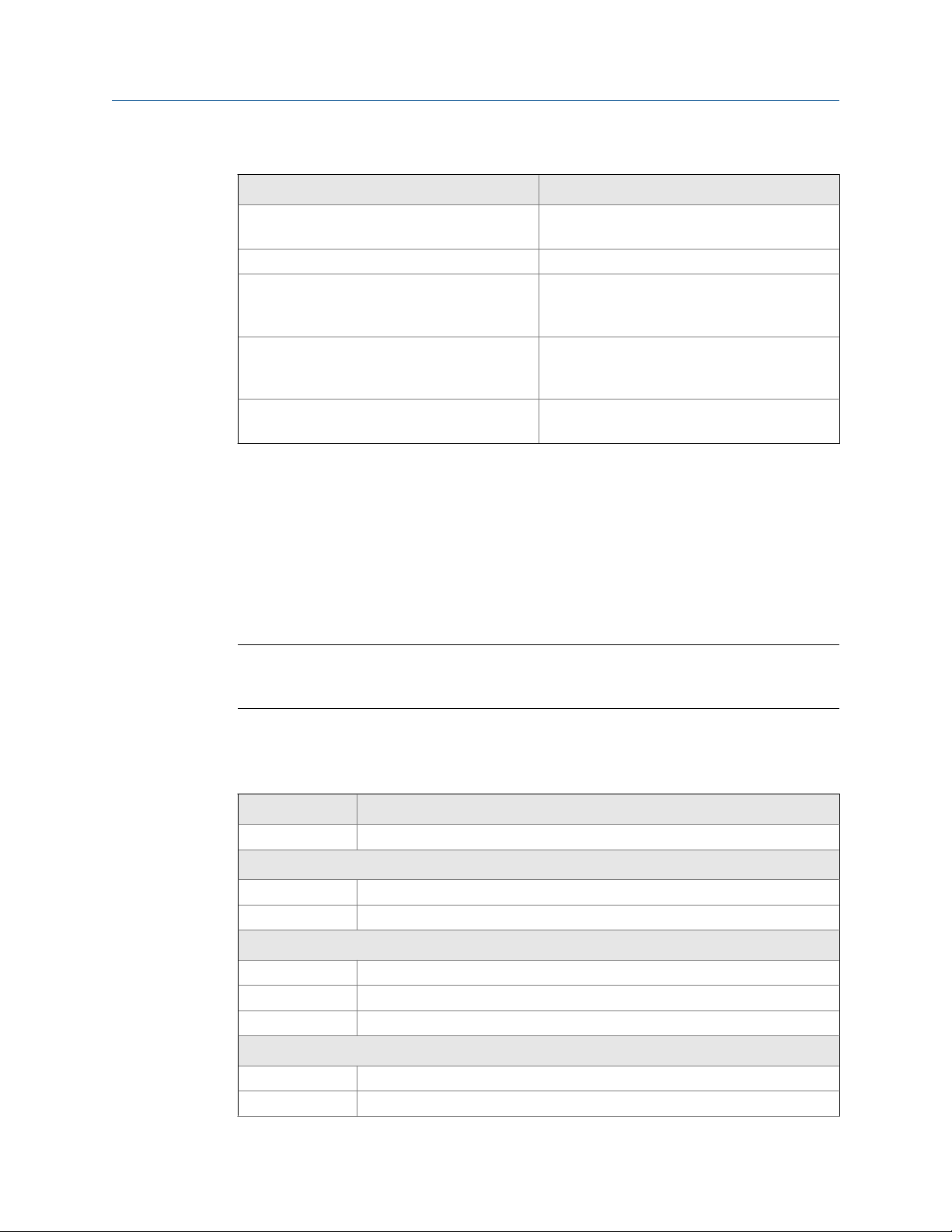
Performance Specifications - Complete SystemTable 1-4:
Physical characteristics Specifications
Linear range 0 to 20 ppm (mg/L) as Cl2 (for higher ranges,
consult factory)
Linearity (per ISO 15839) 0 to 10 ppm: 2%; 0 to 20 ppm: 3%
Response time Following a step change in concentration, the
reading reaches 90% of final value within 7 minutes at 25 °C (77 °F)
Drift At about 1.5 ppm in clean water and constant
temperature, drift is typically less than 0.05
ppm over two weeks.
Detection limit (per ISO 15839) 0.02 ppm (mg/L) in clean water at room tem-
perature
1.3 Ordering information and accessories
Rosemount TCL Reagent-Based Chlorine System
The TCL is used for the continuous determination of total chlorine in water. The TCL
consists of a sample conditioning system, a reagent carboy, a sensor, and a transmitter.
Important
Reagent kits must be ordered separately. Reagent kits for 0-5 ppm and 0-10 ppm chlorine are
available. For higher ranges, consult the factory.
See Table 1-5.
Rosemount TCL Total Chlorine System Ordering InformationTable 1-5:
Model Sensor type
TCL Total Chlorine System
Power input
11 115 Vac 50/60 Hz
12 230 Vac 50/60 Hz
Transmitter
- No selection - no transmitter
280 Rosemount 56-03-24-38-HT, relays, analog/HART
281 Rosemount 56-03-24-38-DP, relays, analog/Profibus DP
Sensor
- No selection - no sensor
30 Rosemount 499ACL-02-54 Total Chlorine Sensor with standard cable
Manual 5
Page 14

Description and Specifications
31 Rosemount 499ACL-02-54-60 Total Chlorine Sensor with optimum EMI/RFI ca-
32 Rosemount 499ACL-02-54-VP Total Chlorine Sensor with VP cable connector
Typical model number: TCL-11-280-32
(1) Interconnecting VP cable sold separately.
Accessories
Part number Description
24134-00 Air pump, 115 Vac, 50/60 Hz
24134-01 Air pump, 230 Vac, 50/60 Hz
9160578 Air pump repair kit
9322052 Check valve for air injection line
24153-00 Carboy for reagent, 5 gal/19 L, includes cap
9100204 Fuse, 0.25 A, 250 V, 3 AG, slow blow for option-11
9100132 Fuse, 0.125 A, 250 V, 3 AG, slow blow for option -12
9380094 Reagent pump, 115 Vac, 50/60 Hz
9380095 Reagent pump, 230 Vac, 50/60 Hz
9380091 Reagent pump replacement tubing
24151-00 Reagent tubing replacement kit
24135-00 Reagent uptake tubing, 6 ft (1.8 m), includes weight
9380090 Sample pump, 115 Vac, 50/60 Hz
9380093 Sample pump, 230 Vac, 50/60 Hz
9380092 Sample pump replacement tubing
24152-00 Sample tubing replacement kit
24164-00 Potassium iodide, 25 g, sufficient for 5 gallons (19 L) of
24164-01 Potassium iodide, 50 g, sufficient for 5 gallons (19 L) of
24165-00 Acetic acid, 2 x 2.5 gal (9.5 L) bottles/case, with 25 g po-
24165-01 Acetic acid, 2 x 2.5 gal (9.5 L) bottles/case, with 50 g po-
Rosemount TCL Total Chlorine System Ordering Information (continued)Table 1-5:
ble
(1)
Sample Conditioning System AccessoriesTable 1-6:
(115 Vac)
(230 Vac)
vinegar (0-5 ppm total chlorine)
vinegar (0-10 ppm total chlorine)
tassium iodide (0-5 ppm total chlorine)
tassium iodide (0-10 ppm total chlorine)
6 Rosemount TCL
Page 15
Description and Specifications
Rosemount 1056 and 56 Transmitters AccessoriesTable 1-7:
Part number Description
23554-00 Cable glands (qty 5 of PG 13.5)
23820-00 Wall and 2 in. pipe mounting kti
240048-00 Stainless steel tag (specify marking)
Sensor AccessoriesTable 1-8:
Part number Description
23501-02 Total chlorine membrane, includes 1 membrane assembly
and 1 O-ring
23502-02 Total chlorine membrane kit, includes 3 membrane as-
semblies and 3 O-rings
9210438 Total chlorine sensor fill solution, 4 oz (120 mL)
For First Time Variopol InstallationsTable 1-9:
Part number Description
23747-06 Interconnecting cable, VP 6, 2.5 ft (0.8 m)
23747-04 Interconnecting cable, VP 6, 4 ft (1.2 m)
23747-02 Interconnecting cable, VP 6, 10 ft (3.0 m)
23747-07 Interconnecting cable, VP 6, 15 ft (4.6 m)
23747-08 Interconnecting cable, VP 6, 20 ft (6.1 m)
23747-09 Interconnecting cable, VP 6, 25 ft (6.1 m)
23747-10 Interconnecting cable, VP 6, 30 ft (9.1 m)
23747-03 Interconnecting cable, VP 6, 50 ft (15.2 m)
23747-11 Interconnecting cable, VP 6, 100 ft (30.5 m)
Manual 7
Page 16

Description and Specifications
8 Rosemount TCL
Page 17

2 Principles of operation
Total chlorine by definition is the iodine produced in a sample when it is treated with
potassium iodide at a pH between 3.5 and 4.5. Typically, acetic acid (or vinegar) is used to
adjust the pH.
The total chlorine system consists of a sample conditioning system, which injects the
reagent into the sample, and a sensor and transmitter, which measure the amount of
iodine produced. Figure 2-1 shows the sample conditioning system. The sample enters the
sample conditioning enclosure and flows to an overflow sampler from which the sample
pump takes suction. Excess sample drains to waste. At the same time, the reagent pump
draws reagent, a solution of potassium iodide in vinegar, from the reagent carboy and
injects it into the suction side of the sample pump. The sample and reagent mix as they
pass through the pump, and total chlorine in the sample is converted to the chemically
equivalent amount of iodine. The flow rates are 11 mL/min for the sample and 0.2 mL/min
for the reagent.
Schematic of Sample Conditioning System and TransmitterFigure 2-1:
Principles of operation
The treated sample next enters the flow cell. Bubbles injected into the flow cell produce
turbulence, which improves the stability of the reading. A membrane-covered
amperometric sensor in the flow cell measures the concentration of iodine. The
transmitter receives the raw signal from the sensor and displays the concentration of total
chlorine. Display units are ppm (mg/L) chlorine as Cl2. The treated sample leaves the flow
cell and drains to waste along with the excess sample.
Manual 9
Page 18

Principles of operation
10 Rosemount TCL
Page 19

3 Installation
3.1 Unpacking and inspection
Complete the following steps when you unpack your instrument.
1. Inspect the shipping containers. If there is damage, contact the shipper immediately
for instructions.
2. Save the box.
3. If there is no apparent damage, unpack the containers.
4. Ensure that all items shown on the packing list are present. If items are missing,
notify Rosemount immediately.
3.2 Installation
Installation
3.2.1 General information
1. Although the transmitter and sample conditioning system are suitable for outdoor
use, do not install them in direct sunlight or in areas of extreme temperature.
CAUTION!
HAZARDOUS AREAS
The TCL Total Chlorine Sample Conditioning System is not suitable for use in hazardous
areas.
2. Install the transmitter and sample conditioning system in an area where vibrations
and electromagnetic and radio frequency interference are minimized or absent.
3. The transmitter is suitable for panel, pipe, or wall mounting. The sample
conditioning enclosure must be mounted on a wall. Provide adequate room beneath
the enclosure for the 5-gallon reagent carboy.
4. Be sure that the distance between the transmitter and sample conditioning cabinet
does not exceed the length of the sensor cable.
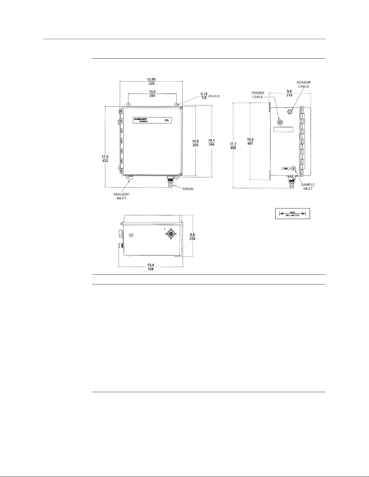
3.2.2 Install the sample conditioning enclosure
Follow the steps below to install the sample conditioning enclosure.
Refer to Figure 3-1, Figure 3-2, and Figure 3-3 for installation details.
Manual 11
Page 20

Installation
Installing the Sample Conditioning EnclosureFigure 3-1:
12 Rosemount TCL
Page 21
Installation
TCL Case DimensionsFigure 3-2:
Reagent Tubing AssemblyFigure 3-3:
Manual 13
Page 22

Installation
Procedure
1. Connect the sample line to the sample conditioning system. Use 1/4 in. OD hard
plastic or stainless steel tubing. If dechlorinated water is being measured, provide a
way for occasionally substituting a chlorinated water sample for the dechlorinated
sample.
Chlorinated water is needed to calibrate the sensor and to check its response.
2. If a grab sample is not already available, install one in the process piping. Choose a
point as close as possible to the sample line supplying the TCL.
Be sure that opening the sample valve does not appreciably alter the flow of sample
to the instrument.
3. Connect the drain to a length of 3/4 in. ID flexible plastic tubing.
Important
The sample must drain to open atmosphere.
4. Find the reagent tubing and fitting in the plastic bag taped to the inside of the
enclosure door. Screw the reagent fitting onto the bulkhead fitting at the bottom
left of the enclosure. Pass the reagent tubing through the hole in the carboy cap. Be
sure the plastic weight will be inside the carboy when the cap is in place. Attach the
reagent tubing to the barbed connector.
See Figure 3-3.
5. Place the blue plastic carboy beneath the enclosure. Screw the cap and tubing
assembly on the carboy.
To prepare reagent, see Section 5.1.
3.2.3 Install the sensor
Complete the following steps to install the Rosemount 499ACL-02 Sensor in the TCL
system.
1. From inside the sample conditioning enclosure, thread the sensor cable or VP cable
through the gland on the upper left side.
Leave about one foot of cable inside the enclosure.
2. Wire the cable to the transmitter.
Refer to Section 4.4.
3. Remove the nut and adapter from the flow cell.
4. Slip the nut over the end of the sensor.
5. Thread the adapter onto the sensor. Hand-tighten only.
6. If you are using a VP cable, connect the cable to the sensor.
The connector and receptacle are keyed to ensure proper mating.
14 Rosemount TCL
Page 23

Installation
7. Once the key has slid into place, tighten the connection by turning the knurled ring
clockwise.
8. Remove the protective cap from the end of the sensor.
9. Insert the sensor in the flow cell. Hand tighten the nut.
Manual 15
Page 24

Installation
16 Rosemount TCL
Page 25

4 Wiring
4.1 Prepare transmitter conduit openings
The transmitter enclosure has six conduit openings. Four conduit openings are fitted with
conduit plugs.
Conduit openings accept 1/2 in. conduit fittings or PG 13.5 cable glands. To keep the case
watertight, block unused openings with NEMA 4X or IP65 conduit plugs.
Note
Use watertight fittings and hubs that comply with the requirements of UL514B. Connect the conduit
hub to the conduit before attaching the fitting to the transmitter (UL508-26 16).
4.2 Provide power to the sample conditioning
Wiring
system
Complete the following steps to power the sample conditioning system.
WARNING!
RISK OF ELECTRICAL SHOCK
Electrical installation must be in accordance with the National Electric Code (ANSI/NFPA-70)
and/or any other applicable national or local codes.
Note
Provide a switch or breaker to disconnect the sample conditioning cabinet from the main power
supply. Install the switch or breaker near the unit and identify it as the disconnecting device for the
sample conditioning system.
Procedure
1. Be sure the pump switches on the wiring access panel are in the Off position.
2. Remove the four screws securing the wiring access panel. Pull the panel out of the
way to reveal the power terminal strip.
3. Insert the power cable through the strain relief connection labeled Power.
See Figure 3-2.
4. Wire the power cable to the terminal strip as shown in Figure 4-1.
Manual 17
Page 26

Wiring
CAUTION!
EQUIPMENT DAMAGE
Do not apply 230 Vac power to a 115 Vac TCL (Model option -11). Doing so will damage
the instrument.
Power wiringFigure 4-1:
Important
Leave the pump power switches off until ready to start up the unit.
See Chapter 5.
4.3 Make power, alarm, output, and sensor connections in the transmitter
WARNING!
RISK OF ELECTRICAL SHOCK
Electrical installation must be in accordance with the National Electrical Code (ANSI/NFPA-70)
and/or any other applicable national or local codes.
4.3.1 Power
Wire AC mains power supply to the power supply board, which is mounted vertically on
the left hand side of the transmitter enclosure beneath the gray plastic cover.
1.
To remove the cover, grab it by the upper edges and pull straight out.
18 Rosemount TCL
Page 27

Wiring
The power connector is at the bottom of the board. See Figure 4-3.
2. Bring the power cable through the conduit opening just below the connector.
3. Unplug the connector from the board and wire the power cable to it.
Lead connections are marked on the connector. (L is live or hot; N is neutral; the
ground connection has the standard symbol.)
4. Replace the cover.
The two tabs at the back edge of the cover fit into slots at the rear of the enclosure,
and the three small slots in the front of the cover snap into the three tabs next to the
relay terminal strip. See Figure 4-3.
5. Once the tabs are lined up, push the cover to snap it into place.
6. AC power wiring should be 14 gauge or greater. Run the power wiring through the
conduit opening nearest the power terminal.
7. Provide a switch or breaker to disconnect the transmitter from the main power
supply.
8. Install the switch or breaker near the transmitter and label it as the disconnecting
device for the transmitter.
4.3.2 Analog output wiring
Four analog current outputs are located on the main circuit board, which is attached to the
inside of the enclosure door.
Figure 4-2 shows the location of the terminals, the outputs they are assigned to, and the
polarity.
Manual 19
Page 28

Wiring
Analog output connectionsFigure 4-2:
The analog outputs are on the main board near the hinged end of the enclosure door.
For best EMI/RFI protection, use shielded output signal cable enclosed in earth-grounded
metal conduit.
Keep output signal wiring separate from power wiring. Do not run signal and power or
relay wiring in the same conduit or close together in a cable tray.
4.3.3 Alarm wiring
The alarm relay terminal strip is located on the power supply board, which is mounted on
the left hand side of the enclosure beneath the gray plastic cover.
See Figure 4-3.
20 Rosemount TCL
Page 29

Wiring
Alarm relay connectionsFigure 4-3:
1. To remove the cover, grab it by the upper edges and pull straight out. The relay
terminal strip is at the top of the board.
2.
Bring the relay wires through the rear conduit opening on the left hand side of the
enclosure and make connections to the terminals strip.
3. Replace the cover. The two tabs on the back edge of the cover fit into slots at the
rear of the enclosure, and the three small slots in the front of the cover snap into the
three tabs next to the relay terminal strip. See Figure 4-3. Once the tabs are lined up,
push the cover to snap it in place.
Keep alarm relay wiring separate from signal wiring. Do not run signal and power or relay
wiring in the same conduit or close together in a cable tray.
4.4 Sensor wiring
If it is necessary to replace the sensor cable, refer to the instructions below.
1. Shut off power to the transmitter.
2. Locate the chlorine signal board.
Slot 1 (left) Slot 2 (center) Slot 3 (right)
Manual 21
Page 30

Wiring
communication input 1 (chlorine) input 2 (optional)
3. Insert the sensor cable through the conduit opening nearest the chlorine board.
4. Slide the board forward to gain access to the wires and terminal screws.
5. Connect the sensor to the chlorine board. Refer to Figure 4-4 or Figure 4-5.
Figure 4-4:
Wiring Sensor with Optimum EMI/RFI or Variopol Cable to
Rosemount 56 Transmitter
Wiring Sensor with Standard Cable to Rosemount 56 TransmitterFigure 4-5:
6. Once the cable has been connected, slide the board fully into the enclosure while
taking up the excess cable through the conduit opening.
If you are using a cable gland, tighten the gland nut to secure the cable and ensure a
7.
sealed enclosure.
4.5 Apply power to the transmitter and complete Quick Start
For Rosemount Total Chlorine System with Rosemount 56 Transmitter
22 Rosemount TCL
Page 31

1. Once all wiring connections are secured and verified, apply power to the
transmitter.
When the transmitter is powered up for the first time, Quick Start screens appear.
The first quick start screen has two control boxes, one for language and the other for
temperature units.
a. The cursor, shown by dark blue backlighting, is on the language control box. To
change the language, press the ENTER/MENU key. A list of available languages,
shown two at a time, appears. Using the Up and Down keys, scroll (see
Section 6.2) to display the choices. Press ENTER/MENU to select the desired
language. Press Down to move the cursor to the temperature control box. To
change units, press ENTER/MENU and scroll to either °F or °C. Press ENTER/MENU
to store the selection.
b. To move to the next screen, use the navigation keys to move the cursor to NEXT
and press ENTER/MENU.
2. The next screen lists navigation rules. Press ENTER/MENU for the next screen.
3. The next step is to configure sensor 1. Sensor 1 is the total chlorine sensor. The
screen has two control boxes.
Wiring
a. For measurement, choose Total chlorine.
b. Choose the desired units, mg/L or ppm.
4. Move the cursor to NEXT and press ENTER/MENU.
The display changes to show some basic keypad operation guidelines.
5. Press ENTER/MENU to show the main display.
The outputs, alarms, display configuration, and data logging are all assigned to
default values. The default value for data logging is disabled.
6. To change the settings, refer to Section 6.5, Chapter 7, and Chapter 9.
Manual 23
Page 32

Wiring
24 Rosemount TCL
Page 33

5 Startup
Complete Chapter 4 before starting this section.
5.1 Prepare the reagent
Complete the following steps to prepare the potassium iodide reagent.
WARNING!
HAZARDOUS SUBSTANCE
The reagent contains potassium iodide dissolved in distilled vinegar or 5% acetic acid. Avoid
contact with skin and eyes. Wash thoroughly after using.
Important
Do not prepare the solution until ready to use.
Startup
Procedure
1. Position the blue plastic carboy under the sample conditioning cabinet. Unscrew the
cap and reagent tube assembly.
2. Add the potassium iodide reagent to the carboy.
See the table.
Amount of KI needed per 5
Expected range, ppm as Cl
0-5 ppm 25 grams 24164-00
0-10 ppm 50 grams 24164-01
0-20 ppm 2 x 50 grams 24164-01
3. Add 5 gallons (19 L) of distilled white vinegar one gallon (4 L) at a time. Swirl the
carboy after each addition.
4. Screw the cap on the carboy. Be sure the reagent uptake tube extends to the
bottom of the carboy.
5. If it hasn't already been connected, connect the reagent tube to the small fitting on
the bottom left hand side of the enclosure.
gal (19 L) of vinegar Part number
2
Note
The shelf life of the potassium iodide vinegar solution is at least two months if stored in the
blue carboy. Do not store the reagent in a container other than the blue carboy. The reagent
is sensitive to sunlight, which the blue carboy effectively blocks.
Manual 25
Page 34

Startup
5.2 Zero the sensor
Complete the following steps to zero the 499ACL-02 Total Chlorine Sensor.
1. Place the sensor in a beaker of deionized water or simply place the sensor in air.
2. Let the sensor operate until the current is stable.
3. Zero the sensor.
See Section 8.4.
5.3 Start sample flow
Adjust the sample flow until a slow stream of liquid is running down the inside tube of the
sampling cup.
5.4 Begin operation and calibrate the sensor
Complete the following steps to start operating the Rosemount TCL and calibrate the
499ACL-02 Sensor.
1. Turn on the reagent and sample pump switches.
Observe that liquid begins to fill the flow cell. The sample flow is about 11 mL/min,
so the flow cell fills rather slowly. Also observe that the air pump is operating.
The pump produces very vigorous bubbling in the flow cell. Once the flow of reagent
starts, it takes about two minutes for the reagent to reach the flow cell. If the
concentration of total chlorine in the sample is greater than about 0.5 ppm, the
treated sample in the flow cell will be pale yellow. Sample containing more chlorine
will be dark yellow.
2. Monitor the sensor current. Once the reading is stable, calibrate the unit.
See Section 8.4. It may take thirty minutes or longer for the reading to stabilize when
the sensor is first put in service.
26 Rosemount TCL
Page 35

6 Display and operation
6.1 Main display
The transmitter has a four line display.
See Figure 6-1. The display can be customized to meet your requirements. See Section 6.5.
Fault or warning messages, if appropriate, appear at the bottom of the screen. See
Section 13.1.
Main displayFigure 6-1:
Display and operation
The following abbreviations are used in the lower two lines of the display. The number
following the display refers to the sensor, alarm relay, or output.
O Output
T Temperature (live)
Tm Temperature (manual)
M Measurement
AL Alarm relay
I Sensor current (chlorine)
Manual 27
Page 36

Display and operation
6.2 Keypad
Local communication with the transmitter is through the membrane keypad.
See Figure 6-2.
Transmitter KeypadFigure 6-2:
6.3 Operation
The operation of the Rosemount 56 Transmitter can best be understood from the
following example.
With the main display showing (Figure 6-1), press ENTER/MENU.
1.
The main Menu, shown below, appears.
Important
Pressing the ENTER/MENU key will bring up the main Menu only if the main display is showing.
Note that the current reading and temperature for sensor 1 (S1) and sensor 2 (S2),
if applicable, always appear at the top of the screen.
The cursor (dark blue backlit field) is on Calibrate.
28 Rosemount TCL
Page 37

2. Press Down to move the cursor to Program.
Press ENTER/MENU.
3.
The cursor is on Outputs, and the first screen in the Outputs submenu is showing.
Display and operation
4. To select a different program submenu, use Right to move the cursor to the desired
tab and press ENTER/MENU.
To enter the Outputs submenu, press Down.
5.
The cursor moves to the first control box, Output. The 56 has four analog outputs,
and this control lets you select which output to configure. The default is output 1.
6. To select a different output, press ENTER/MENU.
A list of the available outputs, shown two at a time, appears.
Manual 29
Page 38

Display and operation
7. To view the list, press and hold Up or Down. To select and store the highlighted
selection, press ENTER/MENU. To move from one control box to another, press Up
or Down.
Some controls require you to select an item from a list. Others, like Dampening,
require you to enter a number.
8. Move the cursor to Dampening at the bottom of the screen.
The default Dampening value is 0 seconds.
9. To change the value, press ENTER/MENU.
The dark blue back-lighting disappears, indicating that a number can be entered.
10. Use the numeric keypad to enter the desired number. If you make an error, press
Left to erase the digit last entered. To store the number, press ENTER/MENU.
Every control box has an information or help screen associated with it.
11.
To view the information screen for the control box the cursor is on, press INFO.
The information screen for Dampening is shown below.
12. To close the information screen, press any key.
A NEXT and BACK button are at the bottom of the screen. NEXT means that
additional control boxes are available on at least one or more screen.
30 Rosemount TCL
Page 39

Display and operation
13. To view the next screen, use the navigation keys (either Down or Right) to move the
cursor to NEXT and press ENTER/MENU.
The next screen in the Outputs submenu appears. The cursor is on the Outputs tab.
14. To enter the screen, press Down.
15. To return to the previous screen, move the cursor to BACK and press ENTER/MENU.
16. To return to the main menu, press EXIT.
6.4 Hold
6.4.1 Purpose
To prevent unwanted alarms and improper operation of control systems or dosing pumps,
place the alarm relays and outputs assigned to the sensor in hold before removing the
sensor for maintenance.
Hold is also useful if calibration, for example, buffering a pH sensor, will cause an out of
limits condition. During hold, outputs assigned to the sensor remain at the last value, and
alarms assigned to the sensor remain in their present state.
6.4.2 Using the Hold function
The Hold function uses certain programming features not discussed in Section 6.3.
Procedure
1. With the main display showing, press ENTER/MENU.
The main menu appears.
Manual 31
Page 40

Display and operation
2. Choose Hold.
The screen below appears. The cursor is on the first checkbox.
3. To hold outputs and relays associated with sensor 1, press ENTER/MENU. A check
appears in the checkbox. To put sensor 2 on hold also, move the cursor to the sensor
2 line and press ENTER/MENU to select the sensor 2 checkbox.
4.
To activate Hold, move the cursor to the APPLY button at the bottom left of the
screen and press ENTER/MENU.
The selected sensor outputs and alarm relays remain on hold until taken out of hold.
However, if power is lost and then restored, hold will automatically be turned off.
The screen describes how to take the transmitter out of hold.
Important
Be sure to press APPLY once the box has been unchecked.
A message stating which sensors are in hold appears in the fault/warning banner at
the bottom of the display.
32 Rosemount TCL
Page 41

6.5 Main display
6.5.1 Configuring the main display
The main display can be configured to meet your specific requirements.
1. With the main display showing, press ENTER/MENU.
The main menu appears.
2. Choose Display Setup.
The screen below appears.
Display and operation
3. Move the cursor to Display setup and press ENTER/MENU.
The screen below appears.
4. Choose Configure main display.
The screen below appears. The position of each control box corresponds to the
position of the variable in the main display.
Manual 33
Page 42

Display and operation
5. Move the cursor to the control box and press ENTER/MENU. Use Up and Down to
scroll through the list of variables and press ENTER/MENU to select the desired
variable for display.
6.5.2 Setting brightness
Complete the following steps to the set the brightness on the 56 Transmitter screen.
1. Move the cursor to the Set brightness button shown in step 3 in Section 6.5.1 and press
ENTER/MENU.
2. Then move the cursor to Display brightness and select the desired brightness.
The information screen gives recommendations about setting the brightness level
especially in areas where the ambient temperature exceeds 50 °C (121 °F).
6.6 Security
6.6.1 How the security code works
Security codes prevent accidental or unwanted changes to program settings or
calibrations.
There are three levels of security:
1.
A user can view the main display and diagnostic screens only.
2. A user has access to the Calibration and Hold menus only.
3. A user has access to all menus.
Procedure
1. If a security code has been programmed, pressing a submenu button (see
Section 6.3) causes the security screen shown below to appear.
2. Enter the three digit security code.
If the entry is correct, the requested submenu appears, and you have access to all
the submenus the code entitles you to.
If the entry is wrong, the Invalid code screen appears.
34 Rosemount TCL
Page 43

6.6.2 Assigning security codes
See Section 7.6
6.6.3 Bypassing security codes
Call the factory.
Display and operation
Manual 35
Page 44

Display and operation
36 Rosemount TCL
Page 45

Programming the transmitter
7 Programming the transmitter
7.1 Entering the Program menus
Complete the following steps to access the Program menus on your 56 Transmitter.
1. With the main display showing, press ENTER/MENU to display the main menu.
2. Move the cursor to Program and press ENTER/MENU.
3. Move the cursor to the tab showing the desired submenu and press ENTER/MENU.
A fifth tab, not shown, labeled pH diagnostics setup, will be present if one of the
sensors is a pH sensor.
Manual 37
Page 46

Programming the transmitter
7.2 Outputs
7.2.1 Menu tree
Figure 7-1 is the Outputs menu tree.
Menu tree for the Outputs submenuFigure 7-1:
7.2.2 Settings
Move the cursor to the appropriate control box and press the desired setting. For more
information about the control box the cursor is on, press INFO. To close the information
screen, press any key.
7.3 Relays
7.3.1 Menu tree
Figure 7-2 is the Relays menu tree.
38 Rosemount TCL
Page 47

Programming the transmitter
Menu tree for the Relays submenuFigure 7-2:
7.3.2 Settings
A large number of relay actions are available in the Model 56.
For more information about a relay action, move the cursor to the Explanation of relay
1.
actions button and press ENTER/MENU.
The screen below appears.
Manual 39
Page 48

Programming the transmitter
2. Select the desired relay action and press INFO to display the information screen.
3.
4. To configure a relay, press EXIT to return to the first screen.
5. Move the cursor to the Configure relay button and press ENTER/MENU.
To close the information screen, press any key.
The totalizer-based relay timer is not available with the model 56 offered as
standard options with the TCL. It is available only if one of the measurements is flow.
A screen similar to the one below appears.
6. Move the cursor to the appropriate control box and make the desired setting.
For more information about the control the cursor is on, press INFO.
7.
8. To close the information screen, press any key.
7.4 Measurement
7.4.1 Menu tree
Figure 7-3 is the Measurement menu tree.
40 Rosemount TCL
Page 49

7.4.2 Settings
Complete the following steps to change the measurement settings on your 56
Transmitter.
Move the cursor to the appropriate control box and make the desired setting.
1.
2. For more information about the control the cursor is on, press INFO.
3. To close the information screen, press any key.
Programming the transmitter
Menu tree for the Measurement submenuFigure 7-3:
7.5 Temperature
7.5.1 Menu tree
Figure 7-4 is the Temperature menu tree.
Menu tree for the Temperature submenuFigure 7-4:
7.5.2 Settings
Complete the following steps to change the temperature settings on your 56 Transmitter.
Manual 41
Page 50

Programming the transmitter
1. Move the cursor to the appropriate control box and make the desired setting.
2. For more information about the control the cursor is on, press INFO.
3. To close the information screen, press any key.
7.6 Security
7.6.1 Menu tree
Figure 7-5 is the Security menu tree.
Menu tree for the Security submenuFigure 7-5:
7.6.2 Settings
Complete the following steps to change the security settings on your 56 transmitter.
Move the cursor to the appropriate control box and make the desired setting.
1.
2. For more information about the control the cursor is on, press INFO.
3. To close the information screen, press any key.
7.6.3 Restoring default settings
See Section 8.6.
42 Rosemount TCL
Page 51
8 Calibration
8.1 Introduction
The Calibrate menu allows you to do the following:
1. Calibrate the RTD (temperature sensing element) in the chlorine and pH sensors.
2. Calibrate the chlorine sensor.
3. Calibrate the analog outputs.
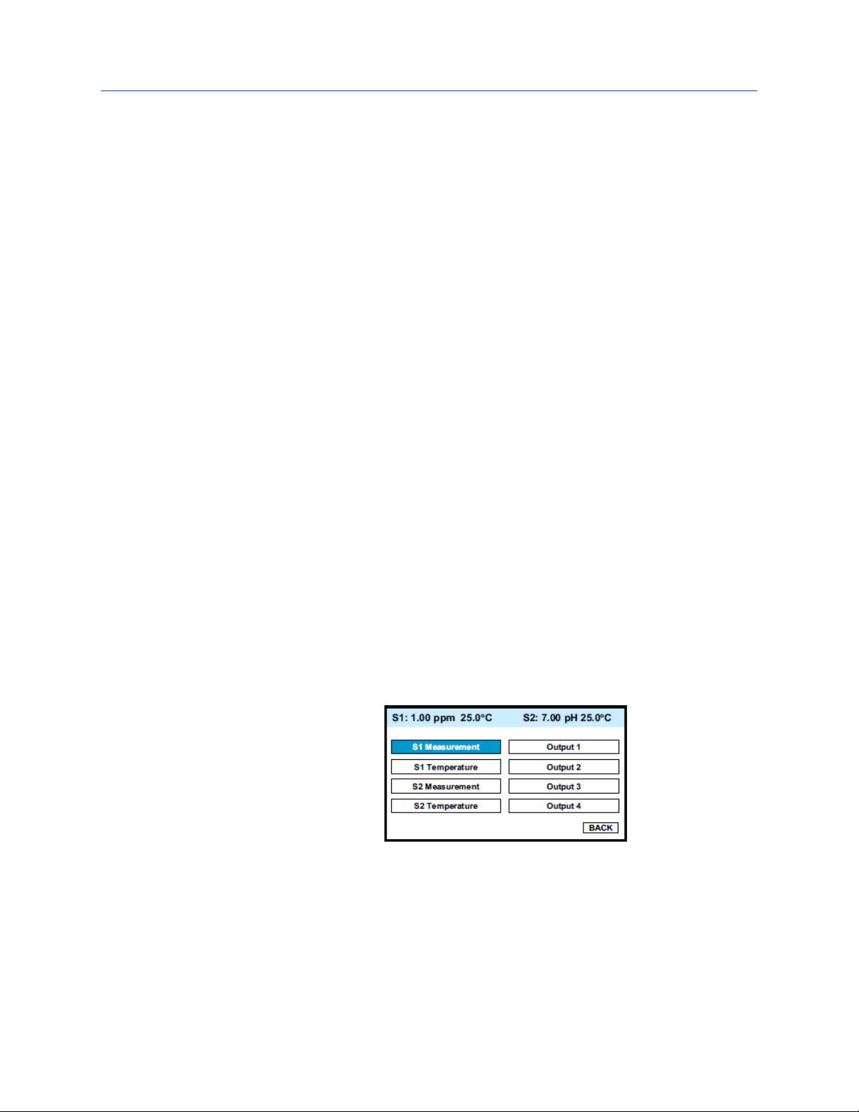
8.2 Entering the Calibration menus
Complete the following steps to enter the Calibration submenus on your 56 Transmitter.
1. With the main display showing, press ENTER/MENU to display the main menu.
Calibration
The cursor is on Calibrate.
2. Press ENTER/MENU.
3. Choose the sensor (measurement or temperature) or output to be calibrated.
Sensor 1 (S1) is the free chlorine sensor; sensor 2 (S2) is the pH sensor (if present).
Manual 43
Page 52

Calibration
8.3 Calibrating temperature
Complete the following steps to calibrate the temperature on your 56 Transmitter.
1. To calibrate the temperature device in the sensor, choose S1 temperature or S2
temperature and follow the prompts.
If you want more information about a calibration step, press INFO.
Once the calibration is correct, the screen shows the results of the calibration. The
screen also shows some acceptance criteria to help you determine whether to
accept the calibration.
2. Press INFO for an information screen to aid with troubleshooting if the calibration
results are not acceptable.
8.4 Calibrating the free chlorine sensor
Complete the following steps to calibrate the free chlorine sensor.
1.
Choose sensor 1 (total chlorine) in Section 8.2.
The screen below appears.
There are two steps to calibrating a free chlorine sensor, measuring the zero current
(Zero) and determining the slope of the calibration curve (Grab). Because stable total
chlorine standards do not exist, the sensor must be calibrated against the results of a
laboratory test run on a grab sample.
To zero the sensor, select Zero and follow the prompts.
2.
For more information about preparing the zero solution and measuring the zero
current, press INFO when prompted.
If the zero step is successful, the transmitter displays the Zero complete screen and
the measured zero current. The screen also shows the typical zero current for the
sensor and the recommended acceptance criterian. You are asked to accept the
zero current. Press INFO for an information screen to aid with troubleshooting if the
results are not acceptable.
If the zero current is badly in error, the transmitter displays the Zero failed screen.
Press INFO for troubleshooting.
44 Rosemount TCL
Page 53

3. To calibrate the sensor response in chlorinated water, select Grab and follow the
prompts.
Be sure the sensor is installed in the flow cell in the TCL and the sample is flowing
down the inside tube of the overflow sampler. Also verify that reagent is being
delivered to the sample and that the air pump is working.
If the calibration is successful, the transmitter displays the Calibration complete
screen and the sensitivity (nA/ppm). The screen also shows the typical sensitivity
range for the sensor and the recommended acceptance criterion. You are asked to
accept the calibration. Press INFO for an information screen to aid with
troubleshooting if the calibration is not acceptable.
If the sensitivity is badly in arror, the transmitter displays the Calibration failed
screen. Press INFO for troubleshooting.
8.5 Calibrating the analog outputs
Complete the following steps to calibrate the analog outputs in your 56 Transmitter.
1.
Choose the appropriate output in Section 8.2 and follow the prompts to trim the
selected output.
Calibration
If you want more information about a calibration step, press INFO.
Once the calibration is complete, the screen shows the results of the calibration. The
screen also shows some acceptance criteria to help you determine whether to
acccept the calibration.
2. Press INFO for an information screen to aid with troubleshooting if the calibration
results are not acceptable.
8.6 Reset
8.6.1 Purpose
There are three resets.
1. Reset all user settings, including calibration and program settings, to the factory
default values. The transmitter will return to Quick Start.
Important
The event logger and data logger will be unaffected.
2. Reset sensor calibration to the default value. The transmitter will clear all user-
entered calibration data for the selected sensor. It will leave all other user-entered
data unaffected.
Manual 45
Page 54

Calibration
3. Reset the analog output calibration for the selected output to the default value. The
transmitter will leave all other user-entered settings unchanged.
8.6.2 Procedure
Complete the following steps to reset your 56 Transmitter.
1. With the main display showing, press ENTER/MENU to display the main menu.
2. Move the cursor to Reset and press ENTER/MENU.
3. Check the desired boxes and press APPLY.
46 Rosemount TCL
Page 55

Data and event logging and retrieval
9 Data and event logging and retrieval
9.1 Overview
Data and event logging is a standard feature in the Rosemount 56 Transmitter. However,
the feature must be enabled.
When data and event logging is enabled, the Rosemount 56 Transmitter will automatically
store the following events with date and time stamp: faults warnings, calibration data,
calibration results (pass or fail), power on/off cycles, hold on/off, and new sensor board
detected. At your discretion, the transmitter will also store alarm activation and
deactivation as events. The event logger holds 300 events. When the capacity of the
logger is reached, the oldest events are removed to make room for new events.
When data/event logging is enabled, the transmitter will automatically store the following
measurement data for total chlorine: date and time, ppm chlorine, temperature, and
sensor current.
The transmitter can store up to 30 days of data. When the capacity of the logger is
reached, the oldest data are removed to make room for new data. Data storage frequency
is every 30 seconds.
9.2 Configuration
Complete the following steps to configure data and event logging and retrieval on your 56
Transmitter.
1. With the main display showing, press ENTER/MENU. Choose Data storage and retrieval.
The screen below appears. The data logger is currently disabled (default).
Manual 47
Page 56

Data and event logging and retrieval
2. To enable the data lotter, move the cursor to Enable data/event logger and press
ENTER/MENU.
3. Make the appropriate date and time settings and choose which alrm relay
activations and deactivations to record as events.
Note
Setting the date or time to an earlier value than the one currently showing will cause data to
be lost form the data/event logger. Download data before resetting time or date. See
Section 9.3.
9.3 Downloading data and events
Complete the following steps to download data and events from your 56 Transmitter to a
USB flash drive.
1. To download data or events, move the cursor to the Download tab and press ENTER/
MENU.
2. Unscrew the USB port cover in the lower right hand corner of the front panel and
insert a USB flash drive in the port.
3. Press the appropriate button to download data or events.
Downloading may take as long as 20 minutes. During download, the display and
keypad are frozen, but all other transmitter functions continue.
Downloaded data and events are stored in a spreadsheet. There is a separate spreadsheet
for every day of data. The finename for downoloaded data is dl mmddyy or dl ddmmyy
depending on the date and time format you select. The filename for downloaded events is
el mmddyy or el ddmmyy.
9.4 Date and time
To reset the date and time from the main Menu, press the Time and Date button.
Note
Setting the date and time to an earlier value than the one showing will cause data to be lost from the
data/event logger. See Section 9.3.
48 Rosemount TCL
Page 57

10 Graphical display
10.1 Overview
The Rosemount 56 Transmitter has a dual graphical display. Each graph can be configured
to meet your requirements, although the time axis on both graphs must be the same. The
time scale can be set to one hour, one day, seven days, or thirty days.
10.2 Configuration
Complete the following steps to configure the graphical display on your 56 Transmitter.
1. With the main display showing, press ENTER/MENU. Choose Display setup.
Graphical display
The screen shown below appears.
2. Configure the displayed variable, the maximum and minimum values for the Y-axis,
and the time scale.
Manual 49
Page 58

Graphical display
3. To view the graphs, move the cursor to the View graph button and press ENTER/
MENU.
The time axis can be expanded or shrunk.
To expand the time scale, use Left or Right to move the pair of dotted green lines to
4.
the area of interest. Press Up to expand the graph. To shrink the time axis, press
Down.
50 Rosemount TCL
Page 59

11 Digital communications
The Rosemount 56 Transmitter has HART communications as a standard feature and
Profibus DP as an option. For more information, refer to the Rosemount 56 HART or
Profibus DP Addendum manuals.
Digital communications
Manual 51
Page 60

Digital communications
52 Rosemount TCL
Page 61

12 Maintenance
12.1 Transmitter
The Rosemount 56 Transmitter used with the TCL requires little routine maintenance.
Clean the transmitter case and front panel by wiping with a clean soft cloth dampened
with water only. Do not use solvents, like alcohol, that might cause a buildup of static
charge.
The sensor circuit board (PN 24203-01) is replaceable. If you have a dual input transmitter,
consult the Rosemount 56 instruction manual for the part number of the other board.
To replace the board:
WARNING!
RISK OF ELECTRICAL SHOCK
Disconnect main power and relay contacts wired to separate power source before servicing.
Maintenance
Procedure
1. Turn off power to the transmitter.
2. Loosen the four screws holding the front panel in place and let the front panel drop
down.
3. Loosen the gland fitting and carefully push the sensor cable up through the fitting as
you pull out the circuit board.
4. Once you have access to the terminal strip, disconnect the sensor.
5. Unplug the sensor board from the main board.
See Figure 12-1.
Manual 53
Page 62

Maintenance
Main Board Showing Connections to Sensor Board(s)Figure 12-1:
6. Slide the replacement board partially into the board slot. Plug the sensor board into
the main board and reattach the sensor wires.
7.
Carefully pull the sensor cable through the gland fitting as you push the sensor
board back into the enclosure. Tighten the cable glands.
8. Close the front panel.
9. Turn on power.
12.2 Total chlorine sensor
12.2.1 General
When used in clean water, the total chlorine sensor requires little maintenance. Generally,
the sensor needs maintenance when the response becomes sluggish or noisy or when
readings drift following calibration. Maintenance frequency is best determined by
experience. For a sensor used in potable water, expect to clean the membrane every
54 Rosemount TCL
Page 63

month and replace the membrane and electrolyte solution every three months. Sensors
used in dirty water require more frequent maintenance and calibration. However, if
experience shows the sensor is holding calibration and not drifting appreciably between
calibration intervals, the maintenance interval can be extended.
12.2.2 Cleaning the membrane
Keep the membrane clean.
Clean the membrane with water sprayed from a wash bottle. Use a soft tissue to gently
wipe the membrane.
12.2.3 Replacing the membrane
Complete the following steps to replace the membrane on the total chlorine sensor.
1. Hold the sensor with the membrane facing up.
2. Unscrew the membrane retainer. Remove the membrane assembly and O-ring.
See Figure 12-2.
3. Inspect the cathode. If it is tarnished, clean it by gently rubbing in the direction of
the existing scratches (do not use a circular motion) with 400-600 grit silicon carbon
finishing paper. Rinse the cathode thoroughly with water.
4. Prepare a new membrane. Hold the membrane assembly with the cup formed by
the membrane and membrane holder pointing up. Fill the cup with electrolyte
solution. Set aside.
5. Put a new O-ring in the groove.
6. Place a drop of electolyte solution on the cathode. Invert the membrane assembly
and place it over the cathode stem.
7. Screw the membrane retainer back in place.
8. Hold the sensor with the membrane pointing down. Shake the sensor a few times,
as though shaking down a clinical thermometer.
Maintenance
12.2.4 Replacing the electrolyte solution and membrane
WARNING!
HARMFUL SUBSTANCE
Fill solution may cause irritation. Avoid contact with skin and eyes. May be harmful if
swallowed..
Procedure
1. Unscrew the membrane retainer.
2. Remove the membrane assembly and O-ring.
See Figure 12-2.
Manual 55
Page 64

Maintenance
Sensor PartsFigure 12-2:
3. Hold the sensor over a container with the cathode pointing down.
Remove the fill plug.
4.
5. Allow the electrolyte solution to drain out.
6. Remove the old pipe tape from the plug.
7. Wrap the plug with two turns of pipe tape and set aside..
8. Prepare a new membrane.
a. Hold the membrane assembly with the cup formed by the membrane and
membrane holder pointing up.
b. Fill the cup with electrolyte solution.
c. Set it aside.
9. Hold the sensor at about a 45° angle with the cathode end pointing up.
10. Add electrolyte solution (PN 9210438) through the fill hole until the liquid
overflows.
11. Tap the sensor near the threads to release trapped air bubbles.
12. Add more electrolyte solution if necessary.
13. Place the fill plug in the electrolyte port and begin screwing it in.
14. After several threads have engaged, rotate the sensor so that the cathode is
pointing up and continue tightening the fill plug.
Do not overtighten.
15. Place a new O-ring in the groove around the cathode post.
16. Cover the holes at the base of the cathode stem with several drops of electrolyte
solution.
17. Insert a small blunt probe, like a toothpick with the end cut off, through the pressure
equalizing port.
See Figure 12-2.
56 Rosemount TCL
Page 65

Maintenance
CAUTION!
EQUIPMENT DAMAGE
Do not use a sharp probe. It will puncture the bladder and destroy the sensor.
18. Gently press the probe against the bladder several times to force liquid through the
holes at the base of the cathode stem. Keep pressing the bladder until no air bubbles
can be seen leaving the holes. Be sure the holes remain covered with electrolyte
solution.
19. Place a drop of electrolyte solution on the cathode; then place the membrane
assembly over the cathode.
20. Screw the membrane retainer in place.
The sensor may require several hours operating at the polarizing voltage to
equilibrate after the electrolyte solution has been replenished.
Spare PartsTable 12-1:
Part number Description
33523-00 Electrolyte fill plug
9550094 O-ring, Viton 2-014
33521-00 Membrane retainer
23501-02 Total chlorine membrane assembly: includes one membrane assembly and
one O-ring
23502-02 Total chlorine membrane kit: includes three membrane assemblies and three
O-rings.
9210438 Total chlorine sensor fill solution , 4 oz (120 mL)
12.3 Sample conditioning system
12.3.1 Reagent
The sample conditioning reagent lasts about two months.
Before putting fresh reagent in the carboy, discard any small amount of remaining
reagent. To prepare the reagent refer to the procedure in Section 5.1. See Table 12-2 for
ordering information.
12.3.2 Sample and reagent tubing
Periodically inspect sample and reagent tubing for cracks and leaks. Replace tubing if it is
damaged.
Manual 57
Page 66

Maintenance
After a period of time, the sample tubing becomes plugged with suspended matter. The
tubing is flexible and difficult to clean mechanically. Plugged sample tubing is best
replaced.
Replacement tubing kits are available. See Table 12-2.
Reagent tubing is shown in Figure 12-3.
Replacing Reagent TubingFigure 12-3:
To replace reagent tubing:
Procedure
1.
Turn off sample and reagent pumps.
2. Luer fittings connect the reagent tubing to the pump. Disconnect the tubing by
turning the fitting in the direction of the arrows shown in Figure 12-5.
3. Disconnect the other end of the suction tubing from the barb on the reagent inlet
fitting in the bottom of the enclosure. Disconnect the other end of the discharge
tubing from the reagent injection tee.
4. Install the replacement tubing.
Note that the discharge tubing is longer than the suction tubing.
12.3.3 Replacing sample tubing
To replace sample tubing:
Sample tubing and tees are shown in Figure.
58 Rosemount TCL
Page 67

Maintenance
Replacing sample tubingFigure 12-4:
Procedure
1.
Turn off the sample and reagent pumps.
2. Luer fittings connect the sample tubing to the pump. Disconnect the tubing by
turning the fitting in the direction of the arrows shown in Figure 12-5.
3. Disconnect the other end of the sample pump suction tubing from the overflow
sampler. Pull the reagent injection tubing off the reagent injection tee.
4. Disconnect the other end of the sample pump discharge tubing from the flow cell.
Pull the air injection tubing off the air injection tee.
5. Disconnect the sample inlet and drain tubing.
6. Install the replacement sample pump suction and discharge tubing assemblies.
The assemblies look similar. To tell the difference, note the air injection tee in the
discharge tubing assembly has a larger diameter barb than the reagent injection tee
in the suction tubing assembly.
7. Install replacement sample inlet and drain tubing.
The sample inlet tubing is longer than the drain tubing.
Manual 59
Page 68

Maintenance
12.3.4 Peristaltic pump tubing
The expected life of the peristaltic pump tubing is one year.
To replace pump tubing:
Procedure
1. Turn off the sample and reagent pumps.
2. The reagent and sample tubing is connected to the pump tubing with luer fittings.
Disconnect the fittings from the pump by turning the fitting in the direction of the
arrow.
See Figure 12-5.
Luer FittingsFigure 12-5:
3. Using your thumb and forefinger, gently pinch the sides of the pump cover. Slide the
cover upwards to remove it.
See Figure 12-6.
Pump CoverFigure 12-6:
4. Using your thumb as shown in Figure 12-7, push the tubing fitting straight outward
until the fitting slides out of the socket.
60 Rosemount TCL
Page 69

Pushing the Tubing Fitting OutFigure 12-7:
5. Remove and discard the pump tubing.
6.
Insert the new tubing one end at a time. Tongues on the sides of the gray fittings at
the end of the tube fit into receiving grooves in the pump casing. Push the fitting in
place until it clicks. Gently stretch the tubing over the rollers and insert the other
fitting into the receiving socket on the other side of the pump.
See Figure 12-8.
Maintenance
Inserting New TubingFigure 12-8:
7. Replace the pump cover.
a.
Place the cover on the pump casing.
See Figure 12-9.
Manual 61
Page 70

Maintenance
Replacing the Pump CoverFigure 12-9:
b. Be sure the pins at the bottom of the cover (Figure 12-10) ride on the tracks in the
pump casing.
PinsFigure 12-10:
c. The position of the track is outlined in Figure 12-11. The pins on the pump cover
must ride in these tracks as the cover is pushed into place. Gently squeeze the
ends of the cover to guide the pins.
TrackFigure 12-11:
d. Push down until the cover snaps into place.
Reconnect the tubing.
8.
62 Rosemount TCL
Page 71

12.3.5 Replacing the air pump
Complete the following steps to replace the air pump on your total chlorine system.
WARNING!
HAZARDOUS VOLTAGE
Can cause severe injury or death. Disconnect power before servicing.
Procedure
1. Disconnect power to the transmitter.
2. Refer to Figure 12-12. Disconnect the reagent and air injection tubes. Disconnect the
suction and discharge tubing by turning the Luer fitting in the direction shown in the
figure. Disconnect the air pump inlet tubing from the barbed tubing in the bottom
of the enclosure.
Replacing the Air PumpFigure 12-12:
Maintenance
3. Remove the four screws (circled in Figure 12-12 and Figure 12-13) holding the air
pump access panel. Pull out the pump and panel.
Air Pump Access PanelFigure 12-13:
4. Disconnect the air inlet and outlet tubing from the air pump.
Manual 63
Page 72

Maintenance
See Figure 12-14.
Air Inlet and Outlet TubingFigure 12-14:
5. Remove the five screws (surrounded by squares in Figure 12-13) holding the air
pump to the access panel.
Remove the four screws holding the wiring access panel.
6.
7. Disconnect the air pump power wires from the terminal strip. Discard the old air
pump.
See Figure 12-15.
Terminal StripFigure 12-15:
8. Remove the five screws holding the rubber base of the replacement air pump to the
body.
9.
Using the five screws removed in step 6, attach the replacement air pump to the
access panel.
10. Connect the air pump power wires to the terminal strip.
11. Replace the wiring access panel.
12. Connect the air inlet and outlet tubing to the air pump.
64 Rosemount TCL
Page 73

Maintenance
See Figure 12-14. The conical end of the check valve points in the direction of the air
flow.
13. Replace the air pump access panel.
14. Connect the sample pump tubing to the pump. Connect the reagent and air
injection tubing. Connect the air inlet tubing to the barbed fitting at the bottom of
the enclosure.
12.3.6 Replacing the air pump diaphragm and check valves
Complete the following steps to replace the air pump diaphragm and check valves on your
total chlorine system.
WARNING!
HAZARDOUS VOLTAGE
Can cause severe injury or death. Disconnect power before servicing.
Procedure
1. Disconnect power to the transmitter.
2. Refer to Figure 12-12. Disconnect the reagent and air injection tubes. Disconnect the
suction and discharge fitting by turning the Luer fitting in the direction shown in the
figure. Disconnect the air pump inlet tubing from the barbed fitting at the bottom of
the enclosure.
3. Remove the four screws (circled in Figure 12-13) holding the air pump access panel.
Pull out the pump and panel.
4. Disconnect the air inlet and outlet tubing from the air pump.
See Figure 12-14.
5. Remove the five screws (surrounded by squares in Figure 12-13) holding the air
pump to the access panel.
6. Pull the rubber base off the pump.
7. Using needle nose pliers, remove the air inlet fitting from the side of the air pump.
See Figure 12-16.
Inlet FittingFigure 12-16:
Manual 65
Page 74

Maintenance
8. Slide the pump assembly out of the air pump body.
See Figure 12-17.
Pump AssemblyFigure 12-17:
9. Following instructions on the package (PN 9160518), replace the diaphragm and
check valves.
10.
Slide the pump assembly back into the pump body and replace the barbed inlet
fitting.
11. Replace the rubber base and screw the pump access panel back onto the air pump.
12. Connect the air inlet and outlet tubing to the air pump.
See Figure 12-14. The conical end of the check valve points in the direction of the air
flow.
13. Replace the air pump access panel.
14. Connect the sample pump tubing to the pump. Connect the reagent and injection
tubing. Connect the air inlet tubing to the barbed fitting at the bottom of the
enclosure.
Replacement Parts and Reagent for Sample Conditioning SystemTable 12-2:
PN Description
24134-00 Air pump, 115 Vac, 60 Hz
24134-01 Air pump, 230 Vac, 50 Hz
9160578 Air pump repair kit
9322052 Check valve for air injection line
24153-00 Carboy for reagent, 5 gal/19 L, includes cap
9100204 Fuse, 0.25 A, 250 V, 3 AG, slow blow for option -11 (115 Vac)
9011132 Fuse, 0.125 A, 250 V, 3 AG, slow blow for option -12 (230 Vac)
9380094 Reagent pump, 115 Vac, 50/60 Hz
9380095 Reagent pump, 230 Vac, 50/60 Hz
9380091 Reagent pump replacement tubing
24151-00 Reagent tubing replacement kit (see Section 12.3.2)
24135-00 Reagent uptake tubing, 65 ft (1.8 m), includes weight
66 Rosemount TCL
Page 75

Maintenance
Table 12-2:
(continued)
PN Description
9380090 Sample pump, 115 Vac, 50/60 Hz
9380093 Sample pump, 230 Vac, 50/60 Hz
9380092 Sample pump replacement tubing
24152-00 Sample tubing replacement kit (includes tees, see Section 12.3.2)
24165-00 Acetic acid, 2 x 2.5 gal (9.5 L) bottles/case, with 25 g potassium iodide
24165-01 Acetic acid, 2 x 2.5 gal (9.5 L) bottles/case, with 50 g potassium iodide
24164-00 Potassium iodide, 25 g, sufficient for 5 gallons (19 L) of vinegar (for 0 - 5 ppm
24164-01 Potassium iodide, 50 g, sufficient for 5 gallons (19 L) of vinegar (for 0 - 10 ppm
Replacement Parts and Reagent for Sample Conditioning System
total chlorine)
total chlorine)
Manual 67
Page 76

Maintenance
68 Rosemount TCL
Page 77

13 Troubleshooting
13.1 Overview
The transmitter continuously monitors itself and the sensor for problems. When the
transmitter identifies a problem, the word warning or fault appears intermittently at
the bottom of the display. To read a fault or warning message and troubleshooting
information, press INFO.
See Section 13.2.
Troubleshooting
Warning
Fault
The instrument or sensor is usable, but you should take steps as soon as
possible to correct the condition causing the warning. Warning messages can
be turned off. To turn off warning messages, go to the main menu and choose
Display setup. Scroll to the Warning tab and turn off warning messages.
The measurement is seriously in error and is not to be trusted. A fault
condition might also mean that the transmitter has failed. Correct fault
conditions immediately. When a fault occurs, the analog output goes to
22.00 mA or to the value programmed in Section 7.2. Fault messages cannot
be turned off.
13.2 Reading and troubleshooting Fault and Warning messages
Complete the following steps to access Fault and Warning messages and determine what
they mean.
1.
With the main display showing, press INFO.
The screen below appears.
Manual 69
Page 78

Troubleshooting
2. Move the cursor to the appropriate button and press ENTER/MENU.
A screen like the one below appears showing all fault or warning messages.
3. For troubleshooting information, press INFO.
13.3 Sensor diagnostics
Sensor diagnostic readings are often useful in troubleshooting measurement problems.
With the main display showing, press INFO.
1.
2. Move the cursor to the Sensor 1 information or Sensor 2 information button and press
ENTER/MENU.
A list of sensor diagnostics appears.
3.
For more information about a specific diagnostic measurement, move the cursor to
the diagnostic of interest and press INFO.
13.4 Troubleshooting calibration problems
If a calibration attempt results in an error or a likely error, the transmitter displays the
appropriate warning screen. For troubleshooting suggestions, press INFO.
70 Rosemount TCL
Page 79

13.5 Other troubleshooting
Problem See Section
Readings are too low. Section 13.5.1
Process readings are erratic or wander. Section 13.5.2
Readings drift. Section 13.5.3
Readings are too high. Section 13.5.4
13.5.1 Readings are low.
1. Does the reagent carboy contain reagent? Is the reagent uptake tubing below the
level of the reagent? Has potassium iodide been added to the acetic acid (vinegar)
reagent?
2. Is there adequate flow to the overflow sampler? Excess sample should be flowing
down the inside tube of the overflow sampler.
3. Does the reagent contain the correct amount of potassium iodide? See the table.
Troubleshooting
Amount of KI needed per 5
Expected range, ppm as Cl
0 - 5 ppm 25 grams 24164-00
0 - 10 ppm 50 grams 24164-01
0 - 20 ppm 2 x 50 grams 24164-01
gallons of vinegar Part number
2
4. Was the comparison or calibration sample tested as soon as it was taken? Chlorine
solutions can be unstable. Test the sample immediately after collecting it. Avoid
exposing the sample to sunlight.
5. Is the membrane fouled or coated? A dirty membrane inhibits diffusion of iodine
through the membrane, reducing sensor current. Clean the membrane by rinsing it
with a stream of water from a wash bottle. Wipe gently with a soft tissue.
6. Are the reagent and sample pumps running? If a pump is not running, check the fuse
and replace it if necessary. See Table 12-2 for part numbers. If the fuse is okay,
replace the pump.
7. Are all the tube fittings tight? Pay particular attention to the Luer fittings that
connect the tubing to the pumps.
8. Does the pump tubing element need replacing? Remove the tubing from the pump
and inspect it. If the tubing appears permanently pinched or deformed, replace the
tubing. Refer to Section 12.3.4 for instructions on how to remove and replace the
tubing elements. The expected life of a tubing element is about one year.
Manual 71
Page 80

Troubleshooting
9. Is the sample flow to the sensor about 11 mL/min? If the sample flow is too low, the
total chlorine reading will be low. If the flow is too high, the ratio between the
sample flow and reagent flow will be too high, and there might be insufficient
reagent to properly react with the total chlorine in the sample. To check sample
flow:
a. Turn off the reagent and sample pumps.
b. Disconnect the reagent tubing at the injection tee. See B in Figure 13-1.
c. Place the end of the tubing in a 5 mL graduated cylinder.
d. Start the reagent pump and collect reagent for ten minutes.
e. Note the volume of reagent collected in the graduated cylinder. After ten
minutes, the volume should be about 2 mL.
10. Is the reagent flow about 0.2 mL/min? If the reagent flow is too low, there might be
insufficient acetic acid to lower the sample pH and insufficient potassium iodide to
react with total chlorine in the sample. To check reagent flow:
a. Turn off the reagent and sample pumps.
b. Disconnect the reagent tubing at the injection tee. See B in Figure 13-1.
c. Place the end of the tubing in a 5 mL graduated cylinder.
d. Start the reagent pump and collect reagent for ten minutes.
e. Note the volume of reagent collected in the graduated cylinder. After ten
minutes, the volume should be about 2 mL.
72 Rosemount TCL
Page 81

Troubleshooting
Figure 13-1:
Disconnecting Sample (A) and Reagent (B) Tubing Prior to Checking
Flow
13.5.2 Process readings are erratic or wander.
1. Is the sensor properly wired to the transmitter? See Section 4.3. Verify that all
connections are tight.
2.
Readings can be erratic when a new sensor is first placed in service. Readings usually
stabilize after about an hour.
3. Is the air pump working? There should be a vigorous stream of bubbles in the flow
cell. The bubbles help mix the sample and keep carbon dioxide bubbles off the
membrane. Carbon dioxide forms when bicarbonate alkalinity in the sample reacts
with acetic acid. The bubbles accumulate in the membrane and eventually break
away, causing the total chlorine reading to wander.
4. Is the membrane damaged or loose? Replace the membrane if necessary.
5. Is the space between the membrane and cathode filled with electrolyte solution,
and is the flow path between the electrolyte reservoir and membrane clear? Often
the flow of electrolyte can be started by simply holding the sensor with the
membrane end pointing down and sharply shaking the sensor a few times as though
shaking down a clinical thermometer. If shaking does not work, try clearing the
holes around the cathode stem. Hold the sensor with the membraned end pointing
up. Unscrew the membrane retainer and remove the membrane assembly. Use the
end of a straightened paper clip to clear the holes at the base of the cathode stem.
Manual 73
Page 82

Troubleshooting
13.5.3 Readings drift.
1. Is the sample temperature changing? Membrane permeability is a function of
temperature. The time constant for the 499ACL-01 sensor is about five minutes.
Therefore, the reading may drift for a while after a sudden temperature change.
2. Is the membrane clean? For the sensor to work properly, iodine must diffuse freely
through the membrane. A coating on the membrane will interfere with the passage
of iodine, resulting in a gradual downward drift in readings. The coating will also
slow the response on the sensor to step changes. Clean the membrane by rinsing
with a stream of water from a wash bottle. Wipe the membrane with a soft tissue.
3. Is the sensor new or has it been recently serviced? New or rebuilt sensors may
require several hours to stabilize.
4. Is the flow of sample past the sensor about 11 mL/min? See Section 13.5.1 step 9 for
more information.
5. Is the reagent flow about 0.2 mL/min? See Section 13.5.1 step 10 for more
information.
13.5.4 Readings are too high
1. Is the sample conditioning reagent clear and colorless? If the reagent is pale yellow,
results will be high. The pale yellow color is caused by iodine, which comes from the
reaction between atmospheric oxygen and potassium iodide. The reaction is
catalyzed by sunlight. The purpose of the blue carboy is to protect the reagent from
sunlight.
2. Is the sensor fill solution fresh? An old,discolored fill solution may produce a high
reading.
13.6 Other troubleshooting - general
Problem See Section
Current output is too low. Section 13.6.1
Alarm relays do not operate properly. Section 13.6.2
13.6.1 Current is output too low.
Load resistance is too high. Maximum load is 600 Ω.
13.6.2 Alarm relays do not operate properly.
1. Verify the relays are properly wired.
2. Verify the relays are properly configured.
74 Rosemount TCL
Page 83

13.7 Simulating inputs - chlorine
To check the performance of the transmitter, use a decade box and 1.5 V battery to
simulate the current from the sensor. The battery, which opposes the polarizing voltage, is
necessary to ensure that the sensor current has the correct sign.
1. Disconnect the anode and cathode leads from terminals 8 and 10 on TB1 and
connect a decade box and 1.5 V battery as shown in Figure 13-2.
Simulating ChlorineFigure 13-2:
Troubleshooting
It is not necessary to disconnect the RTD leads.
2.
Set the decade box to 1.4 MΩ.
3. Note the sensor current.
It should be about 960 nA. The actual value depends on the voltage of the battery.
To view the sensor current, go to the main display and press INFO. Choose sensor 1
information. The input current is the second line in the display.
4. Change the decade box resistance and verify that the correct current is shown.
Calculate current from the equation:
The voltage of a fresh 1.5 volt battery is about 1.6 volt (1600 mV).
13.8 Simulating inputs - temperature
13.8.1 General
The Rosemount 56 Transmitter accepts a Pt100 RTD. The Pt100 RTD is a three-wire
configuration.
See Figure 13-3.
Manual 75
Page 84

Troubleshooting
Three-Wire RTD ConfigurationFigure 13-3:
Although only two wires are required to connect the RTD to the transmitter, using a third (and sometimes
fourth) wire allows the transmitter to correct for the resistance of the lead wires and for changes in the
lead wire resistance with temperature.
13.8.2 Simulating temperature
To simulate the temperature input, wire a decade box to the transmitter as shown in
Figure 13-4.
Simulating RTD InputsFigure 13-4:
To check the accuracy of the temperature measurement, set the resistor simulating the
RTD to the values indicated in the table and note the temperature readings. The measured
temperature might not agree with the value in the table. During sensor calibration, an
offset might have been applied to make the measured temperature agree with a standard
thermometer. The offset is also applied to the simulated resistance. The transmitter is
measuring temperature correctly if the difference between measured temperatures
equals the difference between the values in the table to within ±0.1 °C.
76 Rosemount TCL
Page 85

Troubleshooting
For example, start with a simulated resistance of 103.9 Ω, which corresponds to 10.0 °C.
Assume the offset from the sensor calibration was -0.3 Ω. Because of the offset, the
transmitter calculates temperature using 103.6 Ω. The result is 9.2 °C. Now change the
resistance to 107.8 Ω, which corresponds to 20.0 °C. The transmitter uses 107.5 Ω to
calculate the temperature, so the display reads 19.2 °C. Because the difference between
the displayed temperatures (10.0 °C) is the same as the difference between the simulated
temperatures, the transmitter is working correctly.
Temp. (°C) Pt 100 (Ω)
0 100.0
10 103.9
20 107.8
25 109.7
30 111.7
40 115.5
50 119.4
60 123.2
70 127.1
80 130.9
85 132.8
90 134.7
100 138.5
Manual 77
Page 86

Troubleshooting
78 Rosemount TCL
Page 87

14 Return of material
For any repair, warranty, and return of instrument requests, please contact the factory.
Return of material
Manual 79
Page 88

www.Emerson.com/RosemountLiquidAnalysis
Emerson Automation Solutions
8200 Market Blvd
Chanhassen, MN 55317
Toll Free +1 800 999 9307
F +1 952 949 7001
liquid.csc@emerson.com
www.Emerson.com/RosemountLiquidAnalysis
LIQ-MAN-TCL-56
Rev B
2017
EUROPE
Emerson Automation Solutions
Neuhofstrasse 19a P.O. Box 1046
CH-6340 Baar
Switzerland
T + 41 (0) 41 768 6111
F + 41 (0) 41 768 6300
liquid.csc@emerson.com
www.Emerson.com/RosemountLiquidAnalysis
MIDDLE EAST AND AFRICA
Emerson Automation Solutions
Emerson FZE
Jebel Ali Free Zone
Dubai, United Arab Emirates, P.O. Box 17033
T +971 4 811 8100
F +971 4 886 5465
liquid.csc@emerson.com
www.Emerson.com/RosemountLiquidAnalysis
ASIA-PACIFIC
Emerson Automation Solutions
1 Pandan Crescent
Singapore 128461
Singapore
T +65 777 8211
F +65 777 0947
liquid.csc@emerson.com
www.Emerson.com/RosemountLiquidAnalysis
©
2017 Emerson. All rights reserved.
The Emerson logo is a trademark and service mark of Emerson
Electric Co. Rosemount is a mark of one of the Emerson family of
companies. All other marks are the property of their respective
owners.
 Loading...