

Page 1
Model Solu Comp®II
Dual Input pH/Conductivity Analyzer
Instruction Manual
PN 51-1055pHC/rev.K
February 2006
Page 2
ESSENTIAL INSTRUCTIONS
READ THIS PAGE BEFORE PROCEEDING!
Your purchase from Rosemount Analytical, Inc. has
resulted in one of the finest instruments available for
your particular application. These instruments have
been designed, and tested to meet many national
and international standards. Experience indicates
that its performance is directly related to the quality of
the installation and knowledge of the user in operating and maintaining the instrument. To ensure their
continued operation to the design specifications, personnel should read this manual thoroughly before
proceeding with installation, commissioning, operation, and maintenance of this instrument. If this equipment is used in a manner not specified by the
manufacturer, the protection provided by it against
hazards may be impaired.
• Failure to follow the proper instructions may cause
any one of the following situations to occur: Loss
of life; personal injury; property damage; damage
to this instrument; and warranty invalidation.
• Ensure that you have received the correct model
and options from your purchase order. Verify that
this manual covers your model and options. If not,
call 1-800-854-8257 or 949-757-8500 to request
correct manual.
• For clarification of instructions, contact your
Rosemount representative.
• Follow all warnings, cautions, and instructions
marked on and supplied with the product.
• Use only qualified personnel to install, operate,
update, program and maintain the product.
• Educate your personnel in the proper installation,
operation, and maintenance of the product.
• Install equipment as specified in the Installation
section of this manual. Follow appropriate local
and national codes. Only connect the product to
electrical and pressure sources specified in this
manual.
• Use only factory documented components for
repair. Tampering or unauthorized substitution of
parts and procedures can affect the performance
and cause unsafe operation of your process.
• All equipment doors must be closed and protective
covers must be in place unless qualified personnel
are performing maintenance.
• If this equipment is used in a manner not specified
by the manufacturer, the protection provided by it
against hazards may be impaired.
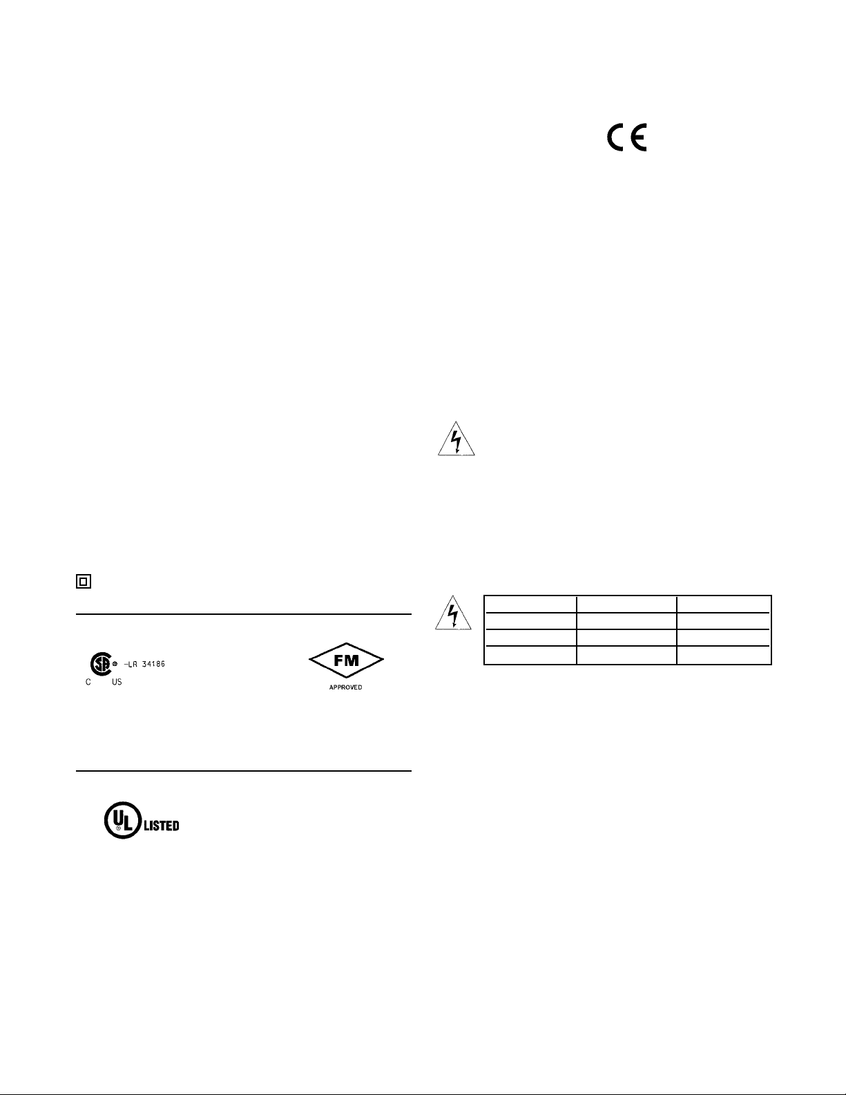
WARNINGS
RISK OF ELECTRICAL SHOCK
Equipment protected throughout by double insulation.
• Installation of cable connections and servicing of this product require access to shock hazard voltage levels.
• Main power and relay contacts wired to separate power
source must be disconnected before servicing.
• Do not operate or energize instrument with case open!
• Signal wiring connected in this box must be rated at least
240 V.
• Non-metallic cable strain reliefs do not provide grounding
between conduit connections! Use grounding type bushings
and jumper wires.
• Unused cable conduit entries must be securely sealed by
non-flammable closures to provide enclosure integrity in
compliance with personal safety and environmental protection requirements. Unused conduit openings must be
sealed with NEMA 4X or IP65 conduit plugs to maintain
the ingress protection rating (NEMA 4X).
• Electrical installation must be in accordance with the
National Electrical Code (ANSI/NFPA-70) and/or any other
applicable national or local codes.
• Operate only with front and rear panels fastened and in
place over terminal area.
• Safety and performance require that this instrument be
connected and properly grounded through a three-wire
power source.
•
Proper relay use and configuration is the responsibility of
the user.
CAUTION
This product generates, uses, and can radiate radio frequency
energy and thus can cause radio communication interference.
Improper installation, or operation, may increase such interference. As temporarily permitted by regulation, this unit has not
been tested for compliance within the limits of Class A computing devices, pursuant to Subpart J of Part 15, of FCC Rules,
which are designed to provide reasonable protection against
such interference. Operation of this equipment in a residential
area may cause interference, in which case the user at his
own expense, will be required to take whatever measures may
be required to correct the interference.
WARNING
This product is not intended for use in the light industrial, residential or commercial environments per the
instrument’s certification to EN50081-2.
Emerson Process Management
Rosemount Analytical Inc.
2400 Barranca Parkway
Irvine, CA 92606 USA
Tel: (949) 757-8500
Fax: (949) 474-7250
http://www.raihome.com
© Rosemount Analytical Inc. 2005
Page 3
QUICK START GUIDE
FOR MODEL SOLU COMP II pH/CONDUCTIVITY ANALYZER
(Model Option 1055-22-30)
1. Refer to Section 2.0 for installation instructions.
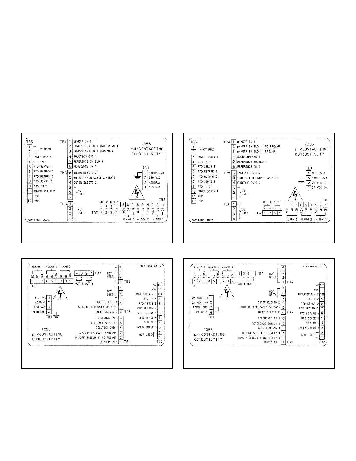
2. Wire sensor(s) to the analyzer. See the drawings below. Refer to the sensor instruction sheet for details. Make alarm
and output connections as shown below.
NOTE
For sensors without solution ground, please use the RC kit included with the instrument.
CONTINUED ON THE FOLLOWING PAGE
3. Once connections are secured and verified, apply power to the analyzer.
Wiring Connections for Solu Comp II Model 1055-01-10
(Panel Mount with 115/230 Vac Power)
Wiring Connections for Solu Comp II Model 1055-02-10
(Panel Mount with 24 Vdc Power)
Wiring Connections for Solu Comp II Model 1055-01-11
(Surface/Pipe Mounting with 115/230 Vac Power)
Wiring Connections for Solu Comp II Model 1055-02-11
(Surface/Pipe Mounting with 24 Vdc Power)
Page 4
5. Choose the desired language. Select >> to show more choices.
6. Choose the number of sensors wired to the analyzer.
NOTE
If One sensor is chosen, only
S1 (pH/ORP) will be available
.
S2 (conductivity) cannot be chosen for single measurement.
7. Select the measurement for sensor 1.
8. Select the measurement for sensor 2. This screen will not appear if one sensor
is selected.
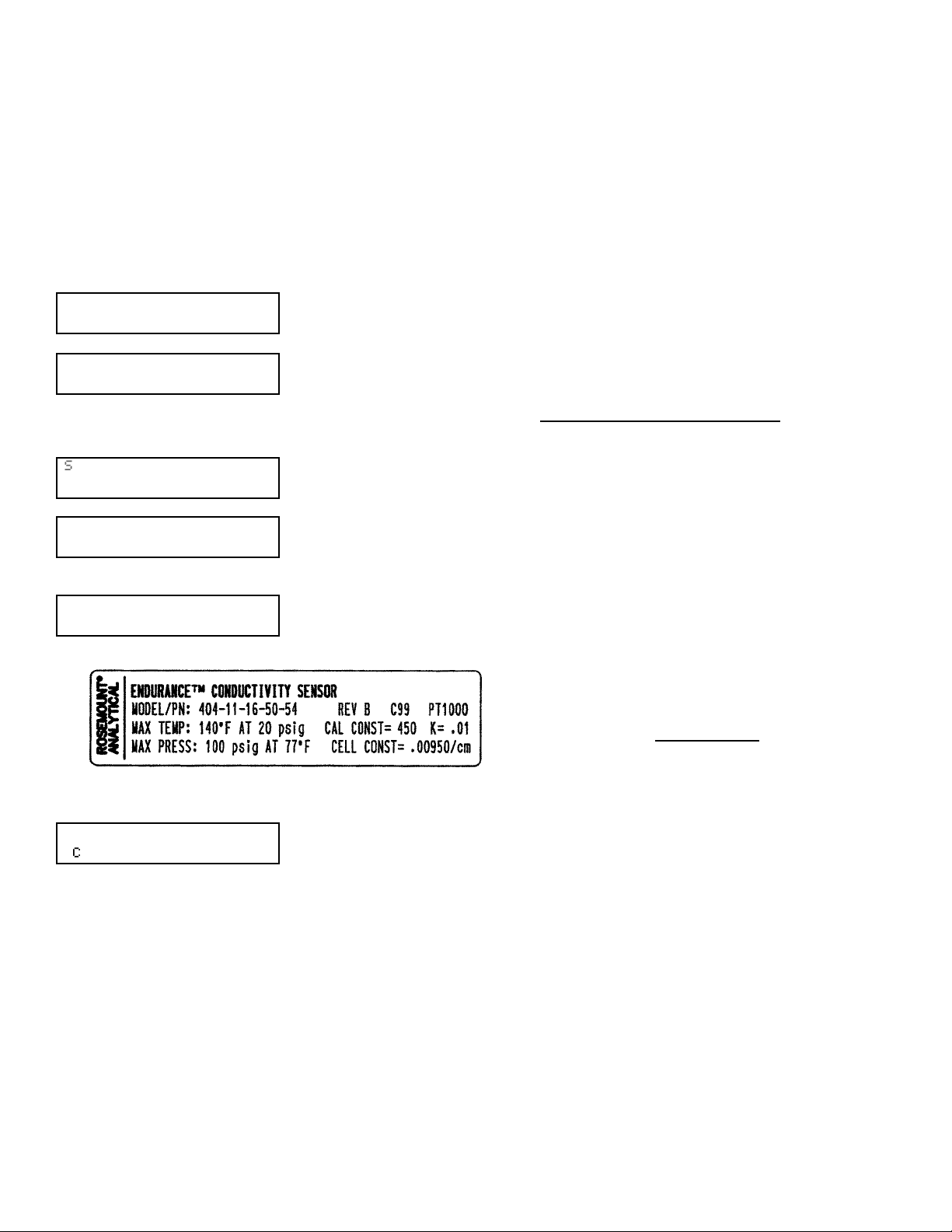
9. Enter the cell constant for the conductivity sensor (sensor 2). See label attached
to sensor.
10. Choose temperature units.
11. The main display appears. The outputs and alarms are assigned to default values. To change settings, refer to Section 5.0, Programming the Analyzer. To
reinstall factory settings and return to Quick Start, see Section 5.10.
# of sensors?
One
TTwwoo
Temperature in?
*
CC
*
F
S1 Measure?
ppHH
Redox ORP
S2 Measure?
CCoonndd
TDS Resistivity
4. When the analyzer is powered up for the first time, Quick Start screens appear. Using Quick Start is easy.
a. A blinking field shows the position of the cursor.
b. Use the or key to move the cursor left or right. Use the or key to move the cursor up or down or to
increase or decrease the value of a digit. Use the or key to move the decimal point.
c. Press ENTER to store a setting. Press EXIT to leave without storing changes. Pressing EXIT also returns the
display to the previous screen.
EEnngglliisshh
Fran ais
Espa ol >>
&
If there is no cell constant on the label, calculate it
from the equation:
cell const = K
500 + cal const
1000
e
j
Cell Constant?
S1:
11
.0000/cm
Page 5
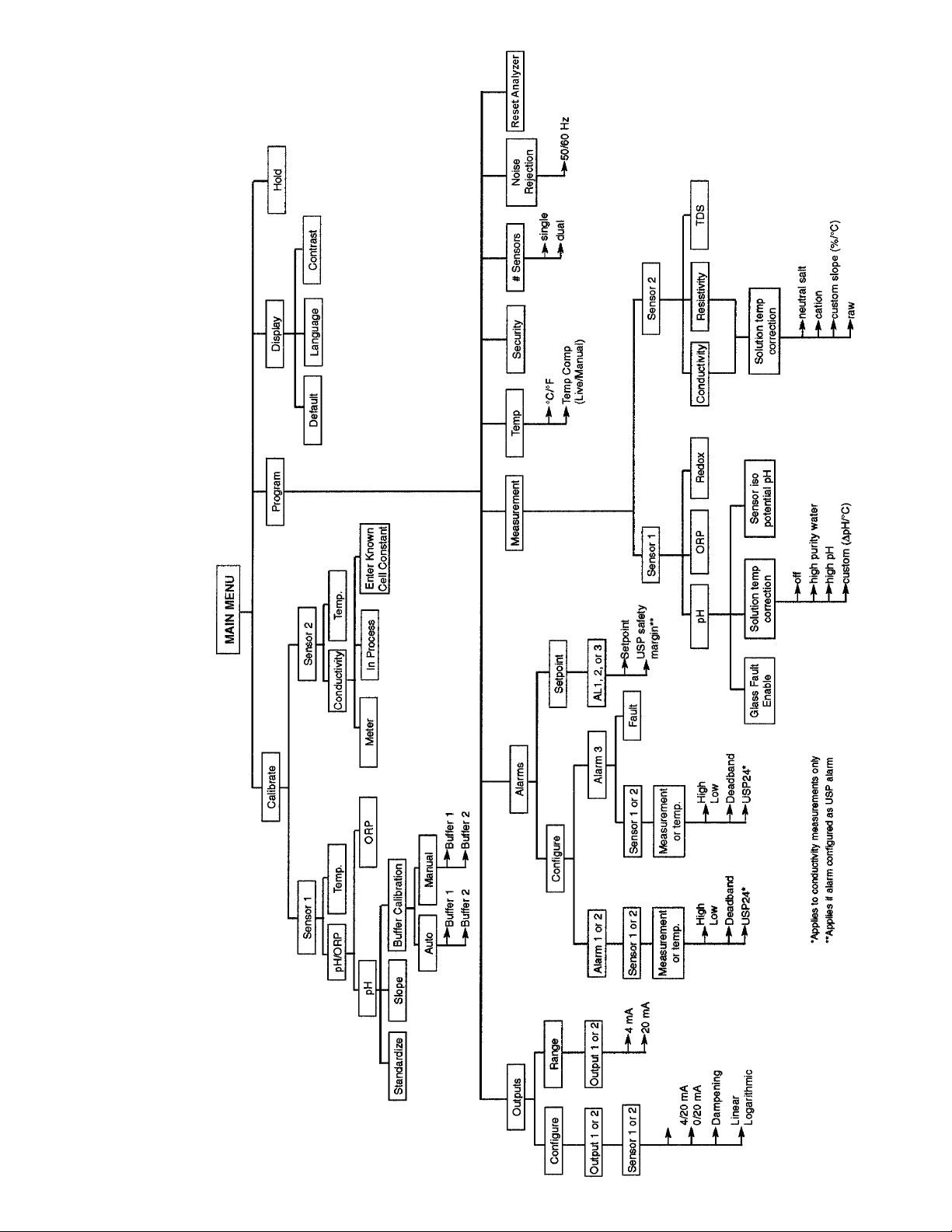
QUICK REFERENCE GUIDE
MENU TREE FOR pH/ORP/REDOX/CONDUCTIVITY/RESISTIVITY/TDS MEASUREMENTS
pH/cond/temp
Page 6

i
MODEL SOLU COMP II TABLE OF CONTENTS
MODEL SOLU COMP II
DUAL INPUT pH/CONDUCTIVITY ANALYZER
TABLE OF CONTENTS
Section Title Page
1.0 DESCRIPTION AND SPECIFICATIONS ................................................................ 1
1.1 Features and Applications........................................................................................ 1
1.2 Specifications........................................................................................................... 2
1.3 Ordering Information ................................................................................................ 8
2.0 INSTALLATION ....................................................................................................... 11
2.1 Unpacking and Inspection........................................................................................ 11
2.2 Installation................................................................................................................ 11
3.0 WIRING.................................................................................................................... 15
3.1 Preparing Conduit Openings.................................................................................... 15
3.2 Power, Alarm, Output, and Sensor Connections ..................................................... 15
4.0 DISPLAY AND OPERATION ................................................................................... 26
4.1 Display ..................................................................................................................... 26
4.2 Keypad..................................................................................................................... 26
4.3 Programming and Calibrating the Solu Comp II - Tutorial ....................................... 27
4.4 Security .................................................................................................................... 28
4.5 Using Hold ............................................................................................................... 28
5.0 PROGRAMMING THE ANALYZER ........................................................................ 29
5.1 General .................................................................................................................... 29
5.2 Changing StartUp Settings....................................................................................... 29
5.3 Configuring and Ranging the Outputs...................................................................... 32
5.4 Configuring Alarms and Assigning Setpoints ........................................................... 34
5.5 Selecting Type of Measurement and Activating Solution Temperature Correction .. 35
5.6 Choosing Temperature Units and Manual/Automatic Temperature Compensation . 40
5.7 Setting a Security Code ........................................................................................... 41
5.8 Noise Rejection........................................................................................................ 42
5.9 Single Sensor or Dual Sensor Input......................................................................... 42
5.10 Resetting Factory Calibration and Factory Default Settings .................................... 43
5.11 Selecting a Default Screen, Language, and Screen Contrast ................................. 43
Page 7

ii
Section Title Page
6.0 CALIBRATION ........................................................................................................ 45
6.1 Introduction .............................................................................................................. 45
6.2 Calibrating Temperature........................................................................................... 46
6.3 Two-Point Buffer Calibration (Auto Calibration) ....................................................... 48
6.4 Two-Point Buffer Calibration (Manual Calibration) ................................................... 50
6.5 Making the Analyzer Reading Match a Second Instrument (Standardization) ......... 52
6.6 Entering a Known Slope .......................................................................................... 53
6.7 ORP Calibration ....................................................................................................... 54
6.8 Calibrating an In-Service Sensor - Conductivity ...................................................... 55
6.9 Placing a New Sensor in Service - Conductivity ...................................................... 59
6.10 Calibrating the Analyzer - Conductivity .................................................................... 60
7.0 MAINTENANCE ..................................................................................................... 62
7.1 Overview .................................................................................................................. 62
7.2 Replacement Parts .................................................................................................. 62
8.0 TROUBLESHOOTING ............................................................................................ 65
8.1 Overview .................................................................................................................. 65
8.2 Troubleshooting Using Fault Codes......................................................................... 65
8.3 Troubleshooting When No Error Message is Showing - pH..................................... 67
8.4 Troubleshooting When No Error Message is Showing - Conductivity...................... 70
8.5 Troubleshooting When No Error Message is Showing - General ............................ 71
8.6 Simulating Inputs - pH.............................................................................................. 72
8.7 Simulating Inputs - Conductivity............................................................................... 73
8.8 Simulating Temperature ........................................................................................... 74
8.9 Measuring Reference Voltage.................................................................................. 75
9.0 RETURN OF MATERIAL ........................................................................................ 76
LIST OF TABLES
Number Title Page
5-1 Default Settings ........................................................................................................ 30
7-1 Replacement Parts for Solu Comp II (Panel Mount Version) ................................... 63
7-2 Replacement Parts for Solu Comp II (Pipe/Surface Mount Version) ........................ 64
MODEL SOLU COMP II TABLE OF CONTENTS
TABLE OF CONTENTS CONT’D
Page 8

MODEL SOLU COMP II TABLE OF CONTENTS
LIST OF FIGURES
Number Title Page
2-1 Panel Mount Installation ........................................................................................... 12
2-2 Pipe Mount Installation ............................................................................................. 13
2-3 Surface Mount Installation........................................................................................ 14
3-1 Removing the Knockouts ......................................................................................... 15
3-2 Wiring Connections for Solu Comp II Model 1055pH-01-10 ....................................
(Panel Mount with 115/230 Vac Power).................................................................... 16
3-3 Wiring Connections for Solu Comp II Model 1055pH-02-10 ....................................
(Panel Mount with 24 Vdc Power) ............................................................................ 16
3-4 Wiring Connections for Solu Comp II Model 1055pH-01-11 ....................................
(Wall/Pipe Mounting with 115/230 Vac Power)......................................................... 17
3-5 Wiring Connections for Solu Comp II Model 1055pH-02-11 ....................................
(Wall/Pipe Mounting with 24 Vdc Power) ................................................................. 17
3-6 Panel Mount Wiring to Models 399-09-62, 400, 401, 402, 403, and 404 ................. 18
3-7 Pipe/Wall Mount Wiring to Models 399-14, 400, 401, 402, 403, and 404 ................ 19
3-8 Pipe/Wall Mount Wiring to Models 399VP-09, 400, 401, 402, 403, and 404............ 20
3-9 Panel Mount Wiring to Models 399VP-09, 400, 401, 402, 403, and 404 ................. 21
3-10 Pipe/Wall Mount Wiring to Models 399-09-62, 400, 401, 402, 403, and 404 ........... 22
3-11 Panel Mount Wiring to Models 399-14, 400, 401, 402, 403, and 404 ...................... 23
3-12 Wiring Model 1055-11-22-32 to Models 399-09-62 and GP-1.................................. 24
3-13 Wiring Model 1055-10-22-32 to Model 399-14......................................................... 25
3-14 Wiring Model 1055 to Models 320HP-58 and 400, 401, 402, 403, or 404 ............... 25
4-1 Displays During Normal Operation........................................................................... 26
4-2 Solu Comp II Keypad ............................................................................................... 26
5-1 Assigning Outputs 1 and 2 ...................................................................................... 32
5-2 High Alarm Logic ..................................................................................................... 34
5-3 Low Alarm Logic ....................................................................................................... 34
6-1 Calibration Slope and Offset .................................................................................... 48
6-2 Calibration Against a Standard Cell .......................................................................... 55
7-1 Exploded View of Solu Comp II (Panel Mount Version) ........................................... 63
7-2 Exploded View of Solu Comp II (Pipe/Surface Mount Version) ................................ 64
8-1 Continuity and Leakage Check ................................................................................ 66
8-2 Simulating Inputs When the Preamplifier is in the Analyzer ..................................... 72
8-3 Simulating pH Input When the Preamplifier is in the Sensor.................................... 72
8-4 Simulating Conductivity ............................................................................................ 73
8-5 Three-Wire RTD Configuration................................................................................. 74
8-6 Simulating RTD Inputs.............................................................................................. 74
8-7 Checking for a Poisoned Reference Electrode ........................................................ 75
iii
Page 9

About This Document
This manual contains instructions for installation and operation of the Solu Comp II
Model 1055 Dual Input pH/Conductivity Analyzer.
The following list provides notes concerning all revisions of this document.
Rev
. Level
Date Notes
0 1/01 This is the initial release of the product manual. The manual
has been reformatted to reflect the Emerson documentation
style and updated to reflect any changes in the product offering.
A 2/02 Revised specs.
B 7/02 Added 399 wiring diagrams.
C 7/02 Added UL specs.
D 11/02 Deleted option code -41.
E 4/03 Revised CE info, maintenance info, and drawing #41055112.
F 3/04 Revised H2SO4 specs & recommended sensors on pages 4 & 6.
G 10/04 Updated mounting drawings on pages 13 & 14.
H 11/04 Updated mounting drawing on page 12.
I 12/04 Revised USP references
J 4/05 Revised panel mount drawing
K 2/06 Revised Case and Analog Output specifications on page 2.
Page 10

MODEL SOLU COMP II SECTION 1.0
DESCRIPTION AND SPECIFICATIONS
SECTION 1.0.
DESCRIPTION AND SPECIFICATIONS
1.1 FEATURES AND APPLICATIONS
1.2 SPECIFICATIONS
1.3 ORDERING INFORMATION AND ACCESSORIES
1
1.1 FEATURES AND APPLICATIONS
The Solu Comp II analyzers offer the choice of single or dual sensor input with measurement choices
of pH/ORP, resistivity/conductivity/TDS, % concentration, ratio conductivity, total and free chlorine, dissolved oxygen, dissolved ozone, flow and temperature. Dual measurement analyzers offer a wide
choice of measurement combinations thus reducing
the cost per loop and needed panel space.
FIELD COMMISSION OPTION: The Solu Comp II
can be ordered with the ability to commission measurements in the field. This added flexibility can
greatly reduce the number of spare instruments
required for field servicing.
QUICK START PROGRAMMING: Exclusive Quick
Start screens appear the first time the Solu Comp II
is powered up. Screen prompts direct the user to
register the number of sensors, the measurement
unit(s) and the language to display. Some measurement specific prompts are also displayed. The
measurement loop is ready for use in a matter of
minutes.
MENUS: Menu screens for calibrating and registering choices are simple and intuitive. Plain language
prompts guide the user through the procedures.
There are no service codes to enter before gaining
access to menus.
DUAL SENSOR INPUT AND OUTPUT: The Solu
Comp II accepts single or dual sensor input. The
two 4-20 mA outputs can be independently programmed to correspond to any selected measurement or temperature. Output damping and linear or
log output may also be field selected.
ALARMS: The Solu Comp II has three fully programmable alarm relays that can be assigned to
any selected measurement or temperature. Alarms
can be configured as high, low, or USP1. The third
relay has the additional choice of fault alarm operation. When selected, a fault alarm will activate the
relay when a sensor or analyzer fault occurs.
ENCLOSURE: The panel mount version fits standard ½ DIN panel cutouts, and its shallow depth is
ideally suited for easy mounting in Hoffman-type
enclosures. A panel mount gasket is included to
maintain the weather rating of the panel.
Surface/pipe mount enclosure includes self-tapping
screws for surface mounting. A pipe mounting
accessory kit is available for mounting to a 2-inch
pipe.
DISPLAY: The two-line, 16-character, back-lit display can be customized to meet user requirements.
All operations and descriptive messages can be
field selected for English, French, German, Italian,
Spanish, or Portuguese. Informative screens, which
permit data not shown in the regular display, may
be seen at the push of a button.
TEMPERATURE: Most measurements (except
ORP and flow) require temperature compensation.
The Solu Comp II will automatically recognize either
a Pt100 or Pt1000 RTD, normally built into the sensor. When this RTD is present, the Solu Comp II
can be set up to display the temperature in °C or °F
as well as set any one or more of the alarms and/or
outputs to respond to this sensor input. If two measurements with temperature are present either can
be chosen for each alarm and output selected.
1
USP alarm applies to conductivity/resistivity only.
Page 11
MODEL SOLU COMP II SECTION 1.0
DESCRIPTION AND SPECIFICATIONS
2
1.2 SPECIFICATIONS - General
Case: ABS (panel-mount), polycarbonate (pipe- and
surface-mount). All versions are NEMA 4X/CSA 4
(IP65).
Dimensions
Panel (code -10): 6.10 x 6.10 x 3.72 in. (155 x
155 x 94.5 mm)
Surface/Pipe (code -11): 6.23 x 6.23 x 3.23 in.
(158 x 158 x 82 mm); see page 5 for dimensions
of pipe mounting bracket.
Conduit openings: Accepts PG13.5 or 1/2 in. con-
duit fittings
Display: Two line, 16-character, back-lit display.
Character height: 4.8 mm. Display can be customized to meet individual requirements.
Depending on number of sensors, as many as 14
display screens are available.
Ambient temperature and humidity: 0 to 50°C, (32
to 122°F) RH 5 to 95% (non-condensing)
Note: The analyzer is operable from -20 to 60°C
(-4 to 140°F) with some degradation in display
performance.
Power:
Code -01: 115/230 Vac ±15%, 50/60 Hz ±6%, 8.0W
Code -02*: 24 Vdc ±15%, 6.0W
Installation Category II
*
For +24Vdc Power Supply use only devices meeting
NEC Class II or UL recognized (UL 1950).
Equipment protected throughout by double insulation.
Hazardous Location:
Class I, Division 2,
Groups A, B, C, & D
POLLUTION DEGREE 4: Extended Environment
Outdoor use where conductive contamination
such as rain, snow, or dust may be present.
(Hazardous Location only)
RFI/EMI: EN-61326
LVD: EN-61010-1
Input: Choice of single or dual sensor input with
measurement choices of pH/ORP, conductivity/
resistivity, toroidal conductivity, flow, chlorine, dissolved oxygen, and dissolved ozone. Field-commissioned units allow user to change measurements on either or both inputs. See combination
guide for valid combinations. For contacting conductivity measurements, temperature element
must be a Pt 1000 RTD. For other measurements, use either a Pt100 RTD, Pt1000 RTD, or
22k NTC (D.O. only).
Outputs: Two 4-20 mA or 0-20 mA isolated outputs.
Continuously adjustable. Linear or logarithmic.
Maximum load 500 ohms. Output dampening with
time constant of 5 sec is user-selectable.
Alarms: Three alarm relays for process measure-
ment(s) or temperature. Alarm 3 can be
configured as a fault alarm, instead of a
process alarm. Each relay can be configured
independently. Alarm logic (high or low activation
or USP*) and deadband are user-programmable.
The USP* alarm can be programmed to activate
when the conductivity is within a user-selectable
percentage of the limit.
*conductivity/resistivity measurement only
Relays: Form C, single pole double throw, epoxy sealed
Terminal Connections Rating: 26-14 AWG wire size
Weight/Shipping weight (rounded up to nearest lb or
nearest 0.5 kg): 3 lb (1.5 kg)/4 lb (2.0 kg)
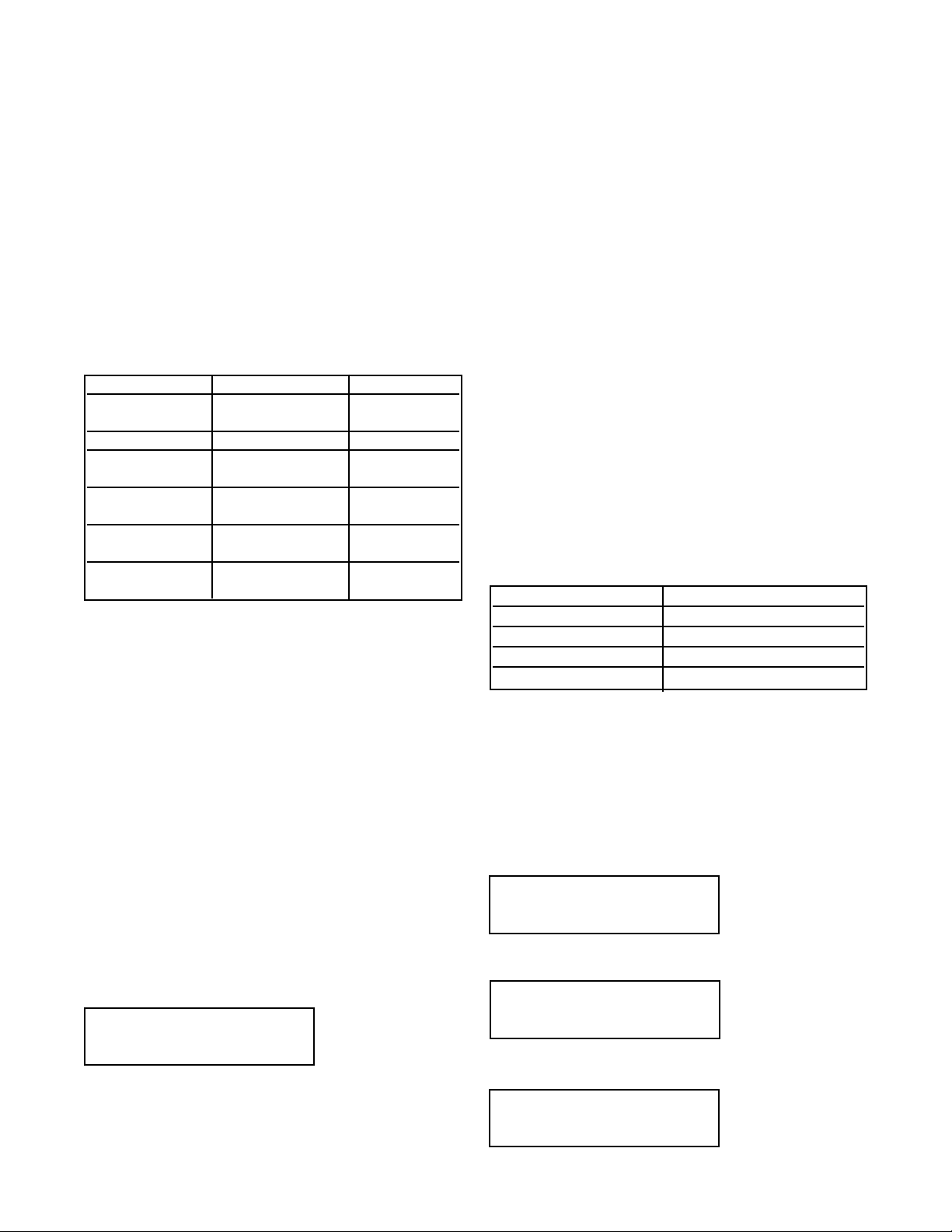
Resistive Inductive
28 Vdc 5.0 A 3.0 A
115 Vac 5.0 A 3.0 A
230 Vac 5.0 A 1.5 A
Ordinary Location: (-68 only)
POLLUTION DEGREE 2: Normally only non-conductive pollution occurs. Occasionally, however, a
temporary conductivity caused by condensation
must be expected.
12RN
Page 12
MODEL SOLU COMP II SECTION 1.0
DESCRIPTION AND SPECIFICATIONS
Measures conductivity in the range 0 to 20,000 µS/cm.
Display choices are conductivity, resistivity, and TDS
(total dissolved solids). Three temperature corrections
are available: high purity water (dilute sodium chloride), cation conductivity (dilute hydrochloric acid),
and adjustable linear temperature coefficient (0 to
5.00%/°C). Temperature correction can be disabled,
allowing the analyzer to display raw conductivity.
PERFORMANCE SPECIFICATIONS -
ANALYZER (CONDUCTIVITY INPUT)
Accuracy (Resistivity)**: 0.9% of reading
Accuracy (Temperature)**: ±0.1°C between 5°C and
100°C; ±1°C between 101°C and 200°C
Stability: 0.5% of reading/month
Ambient Temperature Effect: ±0.05% of reading/°C
Output Accuracy: ±0.1 mA
Temperature correction: High purity water (dilute
sodium chloride), cation conductivity (dilute
hydrochloric acid), linear temperature coefficient
(0.0 to 5.00%/°C), or none. High purity water and
cation conductivity temperature correction apply
between 0 and 100°C. Linear temperature coefficient can be applied between -5 and 200°C.
Measurement Range: 0.0 to 20,000 µS/cm, 0.05 to
20 MΩ-cm, or 0 to 10,000 ppm TDS
Temperature Range: -5°C to 200°C (23°F to 392°F)
1
whichever is greater
2
Accuracy values pertain to Endurance Model 400
Series conductivity sensors only
RECOMMENDED SENSORS FOR
CONDUCTIVITY:
The Solu Comp II is intended for use with the
ENDURANCE Model 400 series conductivity sensor
(Pt 1000 RTD).
Model 400 Screw-in/Insertion
Model 400VP Screw-in/Insertion with 6.0 VP connector
Model 401 Screw-in/Insertion (except 401-15)
Model 402 Retractable
Model 402VP Retractable with 6.0 VP connector
Model 403 Sanitary Flanged
Model 403VP Sanitary Flanged with 6.0 VP connector
Model 404 Flow-Through
The analyzer can also be used with Rosemount
Analytical conductivity sensor Models 140, 141, 142, and
150 having a Pt 100 RTD.
Refer to the table to select the appropriate cell constant.
Ratio Conductivity (Codes -20-30):
The Dual Conductivity Solu Comp II can function as a
ratio analyzer or recovery device (% passage or %
rejection). Product sensor 2’s conductivity reading is
always displayed.
Ratio
%Pass
%Reject
CONTACTING CONDUCTIVITY (Codes -20 and/or -30)
Range Cell constant (/cm) Accuracy
1,2
0.055 - 9.99 µS/cm 0.01 0.9% of reading
or ±0.002 µS/cm
10 - 50 µS/cm 0.01 ±2% of reading
0.055 - 500 µS/cm 0.1 ±2% of reading
or ±0.1 µS/cm
0.055 - 5000 µS/cm 1.0 ±2% of reading
or ±1 µS/cm
0 - 5 mS/cm 1.0 ±2% of reading
or ±0.001 mS/cm
0 - 20 mS/cm 10 ±2% of reading
or ±0.01 mS/cm
Range, µµS/cm Cell constant, /cm
0.0 to 50 0.01
5 to 500 0.1
50 to 5,000 1.0
500 to 20,000 10
12.34 µS/cm 40.3 C
7.34pH 25.3 C
Ratio .3325
S2 4.621 µS/cm
%Passage 12.1
S2 4.621 µS/cm
%Reject 87.9
S2 4.621 µS/cm
3
Page 13
MODEL SOLU COMP II SECTION 1.0
DESCRIPTION AND SPECIFICATIONS
4
When used with Model Series 200 Toroidal
Conductivity Sensors, display choices are conductivity, resistivity, and percent concentration. The percent concentration selection includes the choice of
four common solutions (0-12% NaOH, 0-15% HCl,
and 0-25% or 96-99.7% H2SO4). The conductivityconcentration algorithms for these solutions are fully
temperature compensated. For other solutions, a
simple-to-use menu allows the customer to enter his
own data. The analyzer accepts as many as five (5)
data points and fits either a linear (two [2] points) or
a quadratic function (three [3] or more points) to the
data. Reference temperature and linear temperature
slope may also be adjusted for optimum results.
PERFORMANCE SPECIFICATIONS -
Measurement Range: see table below
Accuracy: ± 1% of reading and ± 0.01 mS/cm
Repeatability: ± 0.5% of reading and ± 0.005 mS/cm
Stability: ± 0.25% of reading and ± 0.005 mS/cm/month,
noncumulative
Ambient Temperature Effect: ± 0.05% of reading/°C
Temperature Compensation: -15 to 200°C (5 to
392°F) automatic or manual. Automatic requires
a Pt100/1000 RTD
Temperature correction: Linear temperature
coefficient (0.0 to 5.00%/°C) neutral salt (dilute
sodium chloride) or none
RECOMMENDED SENSORS:
Model 222 Flow-through conductivity sensor
Model 225 Clean-in-place conductivity sensor
Model 226 Large bore conductivity sensor
Model 228 Toroidal conductivity sensor
Model 242 Flow-through conductivity sensor
Model 247 Economy conductivity sensor
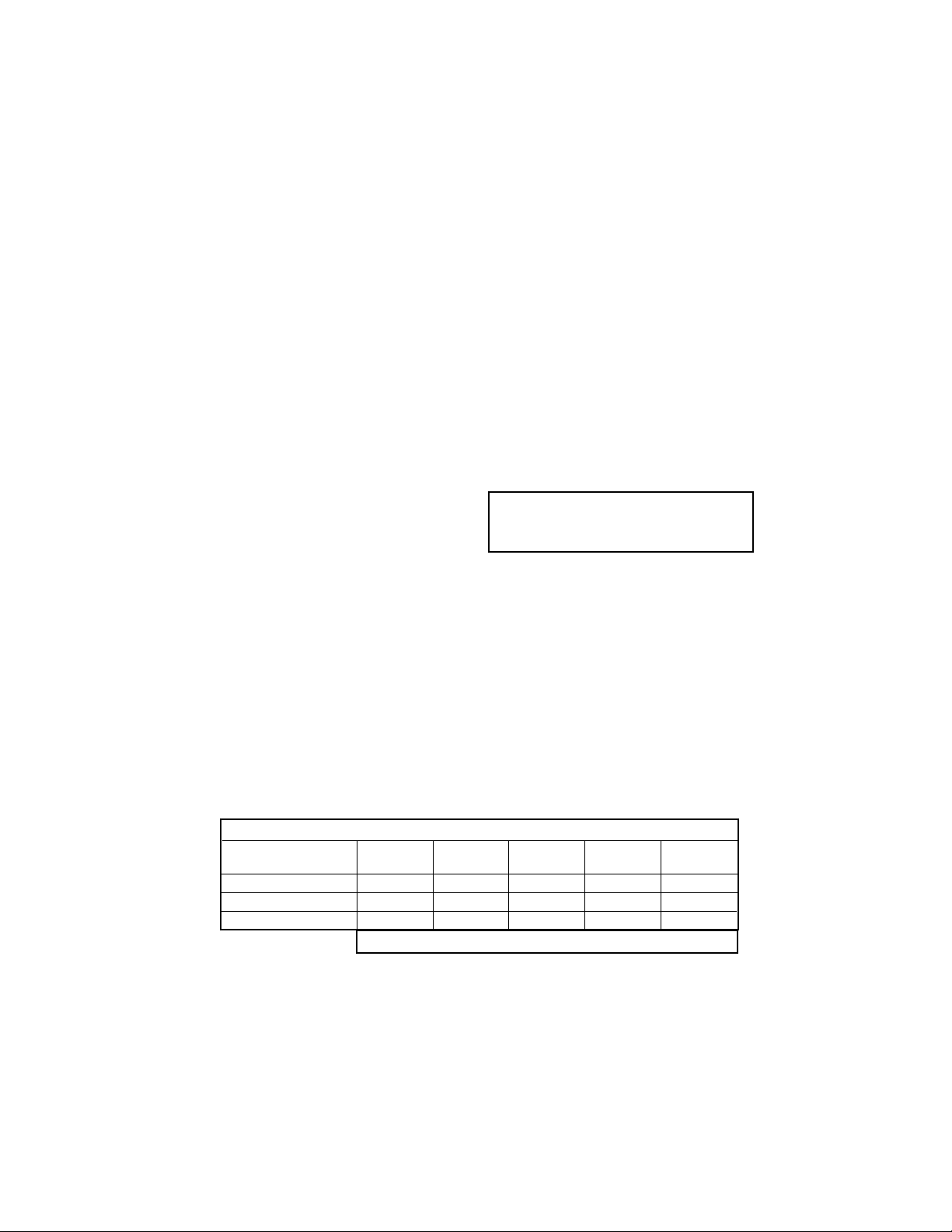
TOROIDAL CONDUCTIVITY (Codes -21 and/or -31)
FULL SCALE MICROSIEMENS/cm
INDUCTIVE SENSORS
Conductivity Sensor
Model Number 226 228 225 222 (1in.) 222 (2 in.)
Cell Constant* 1.0 3.0 3.0 6.0 4.0
Minimum Range 50 250 250 500 500
Maximum Range 1,000,000 2,000,000 2,000,000 2,000,000 2,000,000
* Typical
S1 1027mS/cm 100 C
S2 847.1µS/cm 100 C
Page 14

MODEL SOLU COMP II SECTION 1.0
DESCRIPTION AND SPECIFICATIONS
For use with any standard pH or ORP sensor and all
Uniloc sensors and junction boxes with built-in diagnostic style preamplifiers, display choices are pH,
ORP or Redox. The automatic buffer recognition feature uses stored buffer values and their temperature
curves for the most common buffer standards available worldwide. The analyzer will recognize the value
of the buffer being measured and perform a self stabilization check on the sensor before completing the
calibration. Manual or automatic temperature compensation is keypad selectable. Change in pH due to
process temperature can be compensated using a
programmable temperature coefficient or isopotential
point. Measurement and display of pH glass and reference impedance helps alert the user to sensor
maintenance needs.
*reference impedance is suppressed with amperometric/pH
combinations (-24, -25, -26)
PERFORMANCE SPECIFICATIONS ANALYZER (pH INPUT)
Measurement Range [pH]: 0 to 14 pH
Accuracy: ±0.01 pH
Repeatability: ±0.01 pH
Stability: ±0.01 pH/month, non-cumulative
Temperature Coefficient: ±0.003 pH/°C
Temperature Compensation: Pt100/Pt1000 RTD,
Automatic or Manual -15 to 100°C (5 to 212°F)
Temperature Correction: Choose from standard
measurement compensation, solution temperature
correction for high purity or dilute base solutions,
and custom temperature correction.
PERFORMANCE SPECIFICATIONS ANALYZER (ORP INPUT)
Measurement Range [ORP]: -1400 to +1400 mV
Accuracy: ±2.0 mV
Repeatability: ±1.0 mV
Stability: ±1.0 mV/month, non-cumulative
Temperature Coefficient: ± 0.2 mV/°C
Temperature Measurement: -15 to 100°C
(5 to 212°F)
Temperature Correction: none required
RECOMMENDED SENSORS FOR pH:
Model 320B Flow Through pH
Model 320HP High Purity pH
Model 328A Steam Sterilizable pH
Model 370 and 371 EuroSenz pH
Model 381+ Insertion/Submersion/Flow Through pH
Model 385+ Insertion/Submersion/Retractable pH
Model 389 Insertion/Submersion pH
Model 396 Insertion/Submersion pH
Model 396VP Insertion/Submersion pH with VP 6.0 connector
Model 396P Insertion/Submersion pH
Model 396PVP Insertion/Submersion pH with VP 6.0 connector
Model 396R Retractable pH
Model 396RVP Retractable pH with VP 6.0 connector
Model 397 Quik Disconnect pH
Model 398 Insertion/Submersion pH
Model 398VP Insertion/Submersion with VP 6.0 connector
Model 398R Retractable pH
Model 398RVP Retractable pH with VP 6.0 connector
Model 399 Insertion/Submersion pH
Model Hx338 Steam Sterilizable pH
Model Hx348 Steam Sterilizable pH
When used with conductivity (-20-32 or -22-30):
Model 320HP High Purity pH
Model 381+ Insertion/Submersion/Flow Through pH
Model 385+ Insertion/Submersion/Retractable pH
Model 396P Insertion/Submersion pH
Model 396PVP Insertion/Submersion pH with VP 6.0 connector
Model 396R Retractable pH
Model 396RVP Retractable pH with VP 6.0 connector
RECOMMENDED SENSORS FOR ORP:
Model 330 Flow Through ORP
Model 371 EuroSenz ORP
Model 381+ Insertion/Submersion/Flow Through ORP
Model 385+ Insertion/Submersion/Retractable pH
Model 389 Insertion/Submersion ORP
Model 396P Insertion/Submersion ORP
Model 396PVP Insertion/Submersion ORP with VP 6.0 connector
Model 396R Retractable ORP
Model 398 Insertion/Submersion ORP
Model 398VP Insertion/Submersion with VP 6.0 connector
Model 398R Retractable ORP
Model 398RVP Retractable ORP with VP 6.0 connector
When used with conductivity (-20-32 or -22-30):
Model 320HP High Purity ORP
Model 381+ Insertion/Submersion/Flow Through ORP
Model 385+ Insertion/Submersion/Retractable ORP
Model 396P Insertion/Submersion ORP
Model 396PVP Insertion/Submersion ORP with VP 6.0 connector
Model 396R Retractable ORP
Model 396RVP Retractable ORP with VP 6.0 connector
pH/ORP (Codes -22 and/or -32)
S1 4.34pH 25 C
S2 12.34pH 27 C
5
Page 15

MODEL SOLU COMP II SECTION 1.0
DESCRIPTION AND SPECIFICATIONS
When used with a chlorine specific membrane-covered
amperometric sensor, display choices are free chlorine
or total chlorine. (Total chlorine measurement requires
the use of the Model SCS921 or other sample conditioning system). Because the permeability of the membrane is a function of temperature, a correction is necessary when the sensor is used at a temperature different from the one at which it was calibrated. The
Solu Comp II automatically applies the temperature
correction factor. The process temperature is measured by an RTD in the sensor. An input filter allows the
user to configure the analyzer for rapid response or
low noise. The low noise option is recommended for
samples containing less than 0.1 ppm chlorine.
pH is also a factor in the measurement of free chlorine. An aqueous solution of free chlorine is a mixture
of hypochlorous acid and hypochlorite ion. The relative amount of each depends on the temperature and
pH. Generally, increasing the pH and temperature
reduces the amount of hypochlorous acid in the mixture. Because the response of the sensor to
hypochlorous acid is greater than its response to
hypochlorite, accurate determination of chlorine
requires knowledge of the pH and temperature of the
sample. If the pH is relatively constant, a fixed pH correction factor can be entered into the analyzer. If the
pH is greater than 7 and fluctuates by more than 0.2,
continuous measurement of the pH and automatic pH
correction is necessary. For automatic pH correction,
select code -32 and an appropriate pH sensor.
PERFORMANCE SPECIFICATIONS
Measurement Range: 0-20 ppm (mg/L) chlorine
(as Cl2)
Resolution: 0.001 ppm
Automatic pH Correction (requires Code -32): 5.0
to 9.5 pH
Temperature Correction: Automatic (with Pt100 RTD
in sensor) or manual 0-50°C. Can be disabled if
desired.
Input filter: time constant 1 - 999 sec
RECOMMENDED SENSORS
Chlorine: 499A CL-01 Free Chlorine or 499A CL-02
Total Residual Chlorine (requires sample conditioning)
pH: 399-09-62, 399VP-09, 399-14
For use with most pulse signal flow sensors, the Solu
Comp II's user selectable units of measure include
flow rates in GPM (Gallon per minute), LPM (liters per
minute), or m3/hr (cubic meters per hour), and velocity in ft/sec or m/sec. When configured to measure
flow, the unit also acts as a totalizer in the chosen unit
(gallons, liters, or cubic meters).
Dual flow instruments can be configured as a %
recovery device or a flow difference device.
PERFORMANCE SPECIFICATIONS
Frequency Range: 0.5 - 4000 Hz
Flow Rate: 0 - 9999 GPM, LPM, m3/hr
Totalized Flow: 0 - 9,999,999 Gallons;
37,850,000 Liters; 37,850 m3
Accuracy: ±1% (±1.5% from 3000 to 4000 Hz)
Repeatability: ±1%
RECOMMENDED SENSORS
+GF+ Signet 515 Rotor-X Flow sensor Model
515/8510-XX (PN P51530-PO)
Fluidyne Flow Sensor Model 2300A
(PN Hydro-Flow-2300-A-10-5R-3-1-1)
Consult factory for other pulse type sensor compatibility.
FREE AND TOTAL CHLORINE (Code -24)
FLOW
(Standard on all models or stand alone, Code -23 and/or -33)
S2 12.34 GPM
S2 47.25K Gal
12.34 ppm
26.3 C 8.34pH
6
Page 16

MODEL SOLU COMP II SECTION 1.0
DESCRIPTION AND SPECIFICATIONS
7
When used with an oxygen permeable membranecovered amperometric sensor, display choices are
ppb or ppm dissolved oxygen or % saturation.
Because the permeability of the membrane is a function of temperature, a correction is necessary when
the sensor is used at a temperature different from the
one at which it was calibrated. The Solu Comp II
automatically applies the temperature correction factor. The process temperature is measured by an RTD
in the sensor. Calibrating the analyzer is as simple as
exposing the sensor to air and keying in the barometric pressure. If removing the sensor from the process
is impractical, the analyzer can also be calibrated
against a standard instrument. Solubility correction
factors for liquids containing high concentrations of
electrolytes can be registered into the analyzer. The
Solu Comp II automatically calculates ppb/ppm dissolved oxygen taking into account the high salt concentration.
PERFORMANCE SPECIFICATIONS
Measurement Range: 0-20 ppm (mg/L) dissolved
oxygen; 0- 250% saturation
Resolution: 0.01 ppm; 0.1 ppb for 499A TrDO sensor
(when O2<1.00 ppm); 0.1%
Temperature Correction for Membrane Permeability:
Automatic (with Pt100 RTD in sensor) or manual
0-50°C. Can be disabled if desired.
Input filter: 1- 255 samples
RECOMMENDED SENSORS
Model 499A DO Dissolved Oxygen Sensor
Model Hx438 Steam Sterilizable Dissolved Oxygen
Sensor
Model Gx438 Steam Sterilizable Dissolved Oxygen
Sensor
Model 499A TrDO Trace Dissolved Oxygen Sensor
(soon to be released)
DISSOLVED OXYGEN (Code -25)
For use with an ozone permeable membrane-covered
amperometric sensor. Because the permeability of the
membrane is a function of temperature, a correction is
necessary when the sensor is used at a temperature
different from the one at which it was calibrated. The
Solu Comp II automatically applies the temperature
correction factor. The process temperature is measured by an RTD in the sensor. The Solu Comp II is
calibrated taking a measurement of the ozone level in
the process by an independent chemical method and
setting the display equal to the measured value. An
input filter allows the user to configure the analyzer
for rapid response of low noise. The low noise option
is recommended for samples containing less than 0.1
ppm dissolved ozone.
PERFORMANCE SPECIFICATIONS
Measurement Range: 0-10 ppm (mg/L)
Resolution: 0.001 ppm dissolved ozone
Temperature Correction for Membrane Permeability:
Automatic (with Pt100 RTD in sensor) or
manual 0-35°C. Can be disabled if desired.
Input filter: time constant 1 - 999 sec
RECOMMENDED SENSOR
Model 499A OZ Dissolved Ozone Sensor
LOOP SPECIFICATIONS WITH A MODEL
499A OZ SENSOR
Loop Accuracy: ±5% of reading or ± 3 ppb at 25°C,
whichever is greater
Repeatability: ±2% of reading at a constant tempera-
ture
DISSOLVED OZONE (Code -26)
10.34 ppm
29.3 C 12.34mA
10.34 ppm
29.3 C 12.34mA
Page 17
MODEL SOLU COMP II SECTION 1.0
DESCRIPTION AND SPECIFICATIONS
8
1.3 ORDERING INFORMATION
The Solu Comp II analyzers offer the choice of single or dual sensor input with measurement choices of pH/ORP, conductivi-
ty/resistivity, toroidal conductivity, flow, chlorine, dissolved oxygen, and dissolved ozone. See combination guide (on the following page) for valid combinations. Standard features include two isolated outputs, three alarm relays, customizable two-line
display, and temperature correction.
MODEL 1055 SOLU COMP II ANALYZER
CODE MEASUREMENT 2 (Optional)
30 Contacting Conductivity
31 Toroidal Conductivity
32 pH/ORP
33 Flow
CODE FIELD-COMMISSIONED SUITES (Optional) see tables below
S1 Suite 1 - Field Commissioned Measurement
(basic)
S1A Suite 1 - Field Commissioned Measurement
(includes amperometric)
S2 Suite 2 - Field Commissioned Measurement
(basic)
S2A Suite 2 - Field Commissioned Measurement
(includes amperometric)
CODE OPTIONAL
68 UL Approval
CODE POWER
01 115/230 Vac, 50/60 Hz
02 24 Vdc
CODE MEASUREMENT 1 (Required Selection)
20 Contacting Conductivity
21 Toroidal Conductivity
22 pH/ORP
23 Flow
24 Chlorine
25 Dissolved Oxygen
26 Ozone
CODE MOUNTING
10 Panel mounting enclosure
11 Pipe/Surface mounting enclosure
(Pipe mounting requires accessory kit PN 23820-00)
MODEL 1055 SOLU COMP II ANALYZER
CODE POWER
01 115/230 Vac, 50/60 Hz
02 24 Vdc
CODE MOUNTING
10 Panel mounting enclosure
11 Pipe/Surface mounting enclosure
(Pipe mounting requires accessory kit PN 23820-00)
CODE OPTIONAL
DM Dual Measurement
CODE OPTIONAL
68 UL Approval
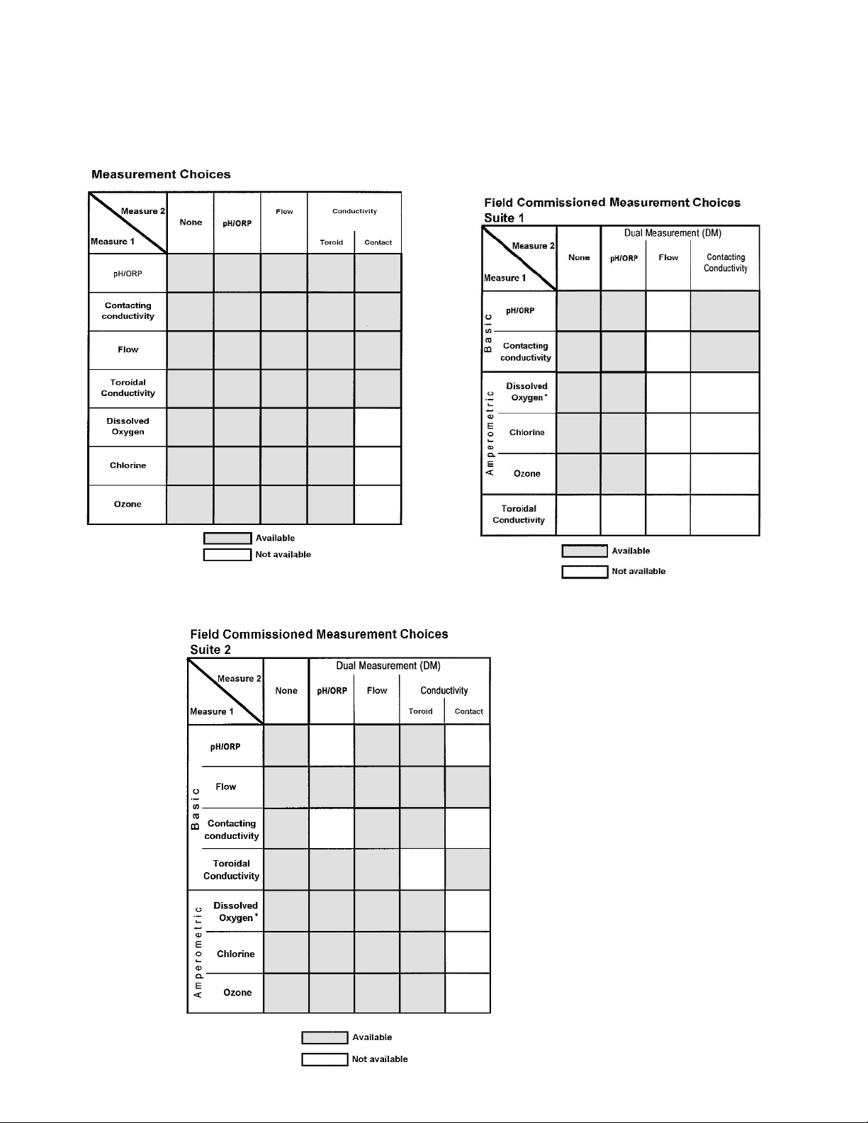
Field Commisssioned Suites option offers the user the ability to commission the Solu Comp II to any valid measurement
combination. This feature provides the benefit of a reduction in the number of spare instruments required to meet emergency
inventory needs. Please refer to the Suites tables (on the following page) for valid measurement combinations. Suites include
a complete set of instrument wiring labels.
Page 18
MODEL SOLU COMP II SECTION 1.0
DESCRIPTION AND SPECIFICATIONS
9
COMBINATION GUIDE
5
5
* For D.O. sensors with 22k thermistor,
use Suite 1 only.
Page 19

MODEL SOLU COMP II SECTION 1.0
DESCRIPTION AND SPECIFICATIONS
10
ACCESSORIES (Weights are rounded up to nearest whole lb or 0.5 kg)
PART NUMBER DESCRIPTION WEIGHT SHIPPING WT.
23820-00 Pipe mounting kit, includes U-bolts, mounting bracket, nuts, 2 lb (1.0 kg) 4 lb (2.0 kg)
washers, and screws (complete)
23554-00 Gland fittings, PG 13.5, 5 per package 1 lb (0.5 kg) 2 lb (1.0 kg)
9240048-00 Tag, stainless steel (specify marking) 1 lb (0.5 kg) 1 lb (0.5 kg)
pH INPUT
9210012 Buffer Solution, 4.01 pH, 16 oz. 1 lb (0.5 kg) 2 lb (1.0 kg)
9210013 Buffer Solution, 6.86 pH, 16 oz. 1 lb (0.5 kg) 2 lb (1.0 kg)
9210014 Buffer Solution, 9.18 pH, 16 oz. 1 lb (0.5 kg) 2 lb (1.0 kg)
CONDUCTIVITY INPUT
SS-1 Conductivity Standard, 1409 µS/cm at 25°C, 1 quart (945 mL) 2 lb (1.0 kg) 4 lb (2.0 kg)
SS-1A Conductivity Standard, 1409 µS/cm at 25°C, 1 gallon (3785 mL) 9 lb (4.0 kg) 11 lb (5.0 kg)
SS-5 Conductivity Standard, 1000 µS/cm at 25°C, 1 quart (945 mL) 2 lb (1.0 kg) 4 lb (2.0 kg)
SS-5A Conductivity Standard, 1000 µS/cm at 25°C, 1 gallon (3785 mL) 9 lb (4.0 kg) 11 lb (5.0 kg)
SS-6 Conductivity Standard, 200 µS/cm at 25°C, 1 quart (945 mL) 2 lb (1.0 kg) 4 lb (2.0 kg)
SS-6A Conductivity Standard, 200 µS/cm at 25°C, 1 gallon (3785 mL) 9 lb (4.0 kg) 11 lb (5.0 kg)
SS-7 Conductivity Standard, 5000 µS/cm at 25°C, 1 quart (945 mL) 2 lb (1.0 kg) 4 lb (2.0 kg)
SS-7A Conductivity Standard, 5000 µS/cm at 25°C, 1 gallon (3785 mL) 9 lb (4.0 kg) 11 lb (5.0 kg)
Page 20

11
SECTION 2.0.
INSTALLATION
MODEL SOLU COMP II SECTION 2.0
INSTALLATION
2.1 UNPACKING AND INSPECTION
2.2 INSTALLATION
Type of Mounting Section
Panel 2.2.2
Pipe 2.2.3
Surface 2.2.4
2.1 UNPACKING AND INSPECTION
Inspect the shipping container. If it is damaged, contact the shipper immediately for instructions. Save the box. If
there is no apparent damage, unpack the container. Be sure all items shown on the packing list are present. If
items are missing, notify Rosemount Analytical immediately.
2.2 INSTALLATION
2.2.1 General Information
1. Although the analyzer is suitable for outdoor use, do not install it in direct sunlight or in areas of extreme temperatures.
2. Install the analyzer in an area where vibrations and electromagnetic and radio frequency interference are minimized or absent.
3. Keep the analyzer and sensor wiring at least one foot from high voltage conductors. Be sure there is easy
access to the analyzer.
4. AC power and relay wiring should not enter via top conduit openings and should be kept separated
from other wiring in the analyzer after installation.
5. The analyzer is suitable for panel, pipe, or surface mounting. Refer to the table below.
6. See Section 3.1 for removal of conduit knockouts.
7. To reduce the likelihood of stress on wiring connections, the hinged front panel (-11 models) shall not be
removed from the base during wiring installation, and there shall be sufficient wire leads to avoid stress on conductors.
8. For UL-approved models (-68), the clear wiring shield must be installed prior to operation.
Page 21
12
MODEL SOLU COMP II SECTION 2.0
INSTALLATION
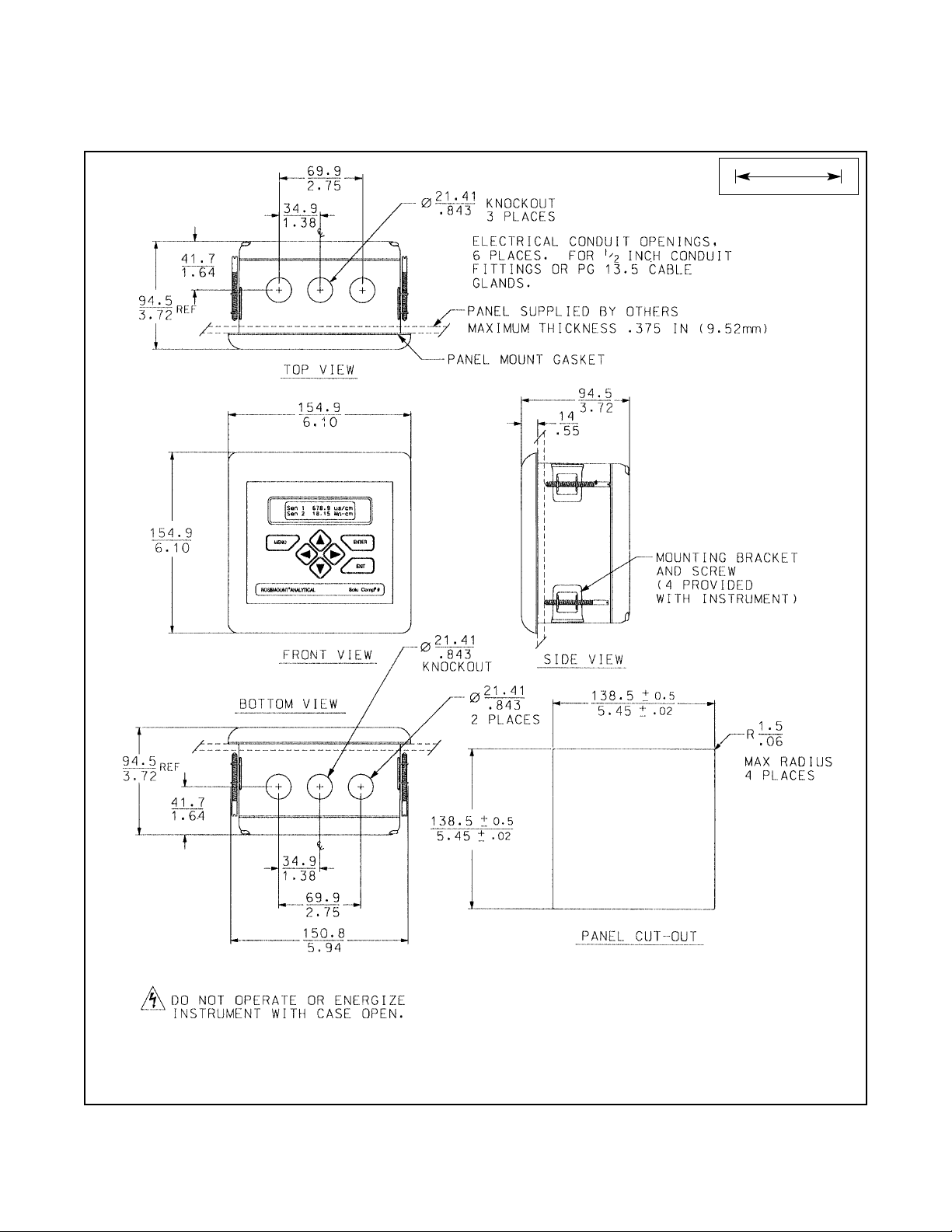
FIGURE 2-1. Panel Mount Installation
Access to the wiring terminals is through the rear cover. Four screws hold the cover in place.
2.2.2 Panel Mounting.
MILLIMETER
INCH
Page 22
MODEL SOLU COMP II SECTION 2.0
INSTALLATION
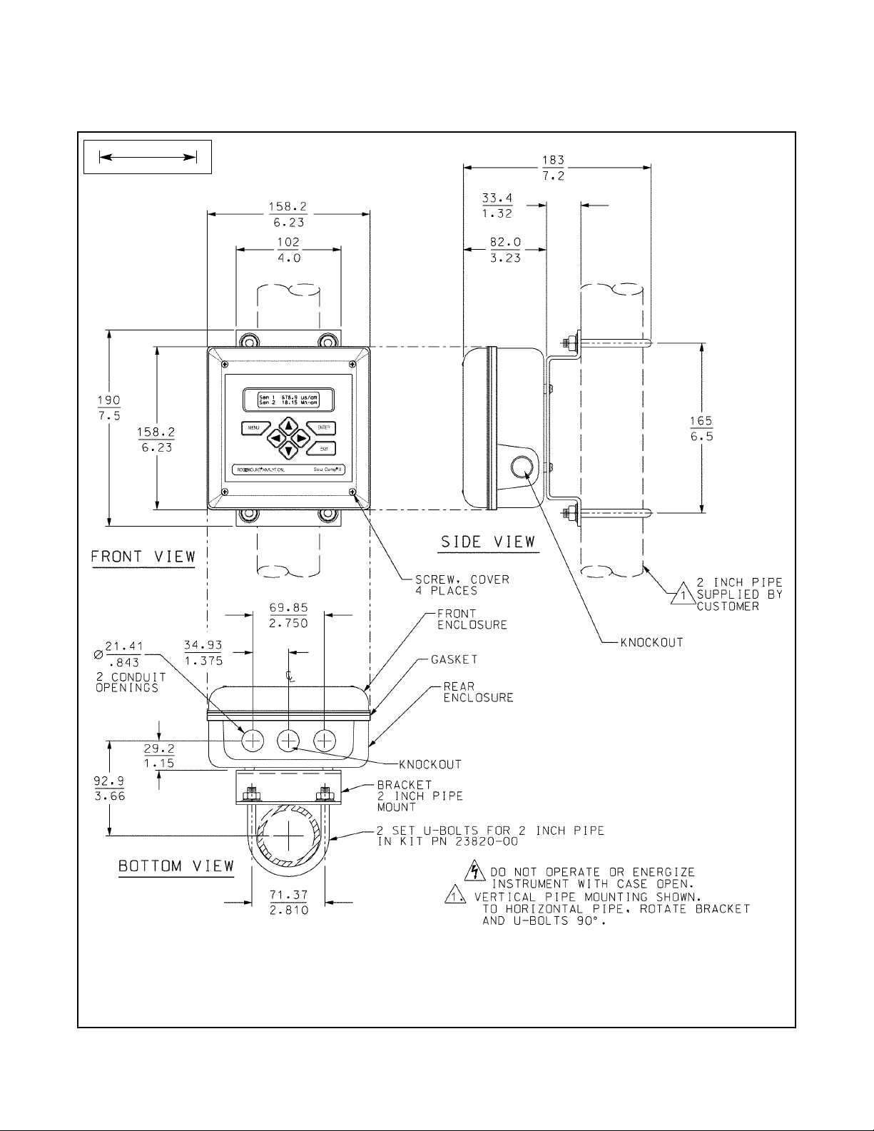
FIGURE 2-2. Pipe Mount Installation
The front panel is hinged at the bottom. The panel swings down for access to the wiring terminals.
2.2.3 Pipe Mounting.
MILLIMETER
INCH
13
Page 23
MODEL SOLU COMP II SECTION 2.0
INSTALLATION
14
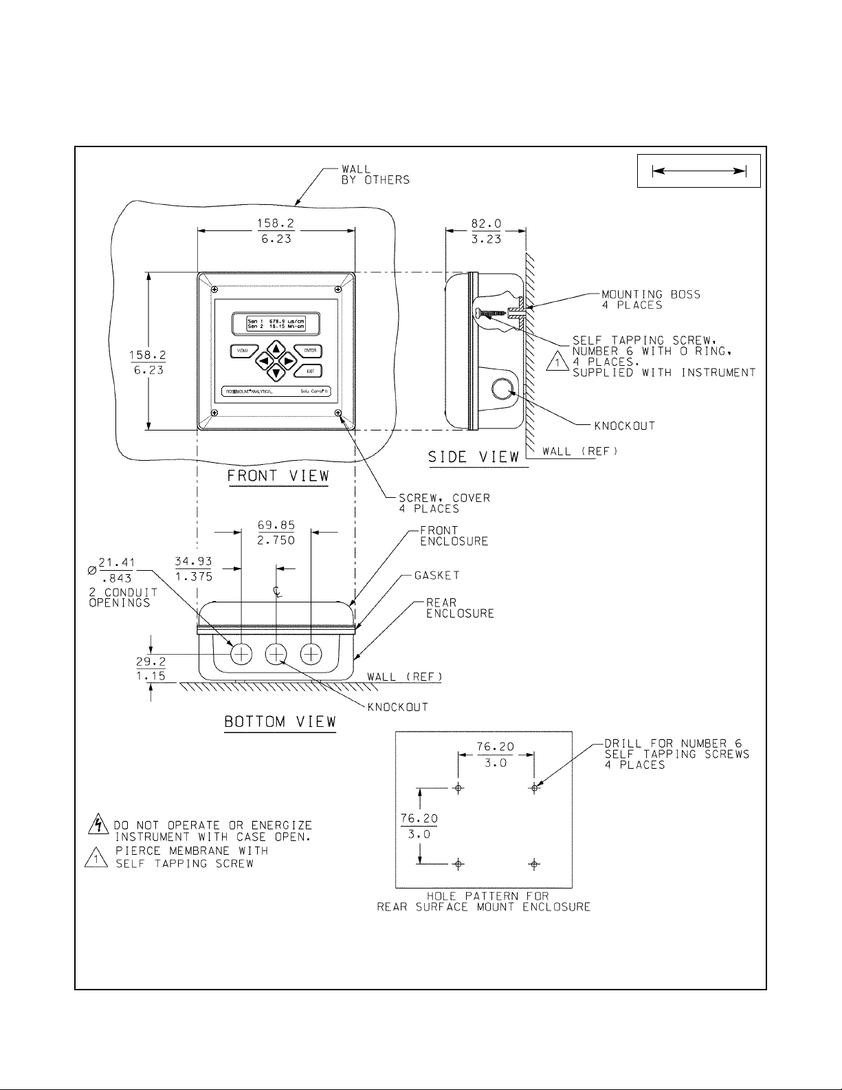
FIGURE 2-4. Surface Mount Installation
The front panel is hinged at the bottom. The panel swings down for access to the wiring terminals.
2.2.4 Surface Mounting.
MILLIMETER
INCH
Page 24
3.2 POWER, ALARM, OUTPUT, AND SENSOR CONNECTIONS
The Solu Comp II is available in two mounting configurations.The positions of the power, alarm, output, and sensor terminal blocks are different in each. Refer to the table to find the correct drawing.
For best EMI/RFI protection use
shielded output signal cable
enclosed in an earth-grounded
metal conduit. Connect the
shield to earth ground at terminal 4 on TB1.
AC wiring should be 14 gauge or greater. Provide a switch or breaker to disconnect the analyzer from the main power
supply. Install the switch or breaker near the analyzer and label it as the disconnecting device for the analyzer.
Keep sensor and output signal wiring separate from power wiring. Do not run sensor and power wiring in the same
conduit or close together in a cable tray.
NOTE
For sensors without solution ground, please use the RC kit included with the instrument.
MODEL MOUNTING POWER FIGURE
1055pH-01-10 Panel 115/230 Vac 3-2
1055pH-02-10 24 Vdc 3-3
1055pH-01-11 Surface/Pipe 115/230 Vac 3-4
1055pH-02-11 24 Vdc 3-5
WARNING: RISK OF ELECTRICAL SHOCK
AC connections and grounding must be in compliance
with UL 508 or local electrical code. DO NOT apply
power to the analyzer until all electrical connections are
verified and secure.
SECTION 3.0.
WIRING
3.1 PREPARING CONDUIT OPENINGS
3.2 POWER, ALARM, OUTPUT, AND SENSOR
CONNECTIONS
MODEL SOLU COMP II SECTION 3.0
WIRING
3.1 PREPARING CONDUIT OPENINGS
The number of conduit openings and the location depend on
the model.
Conduit openings accept 1/2-inch conduit fittings or PG 13.5
cable glands. To keep the case watertight, block unused
openings with NEMA 4X or IP65 conduit plugs.
NOTE
Use watertight fittings and hubs that comply with the
requirements of UL514B. Connect the conduit hub to the
conduit before attaching the fitting to the analyzer (UL508-
26.16).
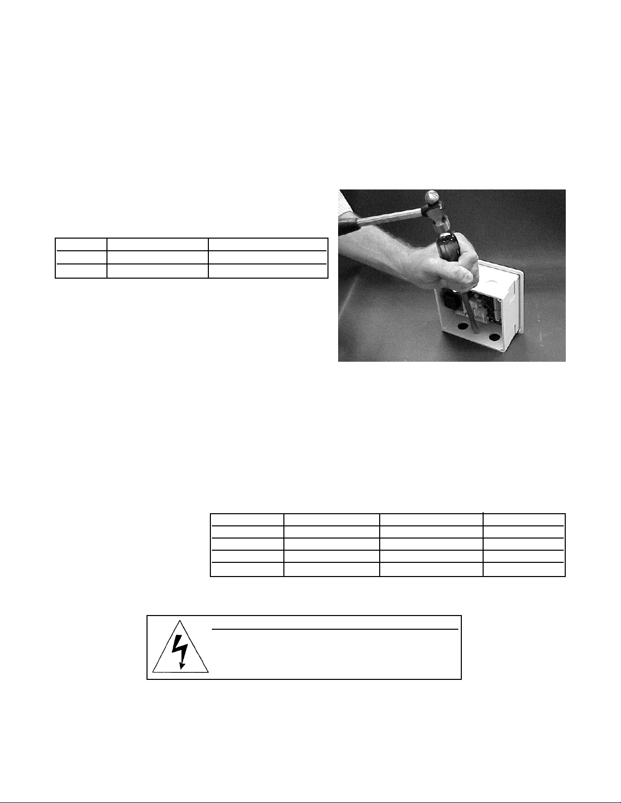
Figure 3-1 shows how to remove the knockouts. The knockout grooves are on the outside of the case. Place the
screwdriver blade on the inside of the case and align it approximately along the groove. Rap the screwdriver sharply
with a hammer until the groove cracks. Move the screwdriver to an uncracked portion of the groove and continue
the process until the knockout falls out. Use a small knife blade to remove the flash from the inside of the hole.
FIGURE 3-1. Removing the Knockouts
Model Description Conduit openings
1055-10 panel mount two open, three knockouts
1055-11 surface or pipe mount three open, no knockouts
15
Page 25
16
MODEL SOLU COMP II SECTION 3.0
WIRING
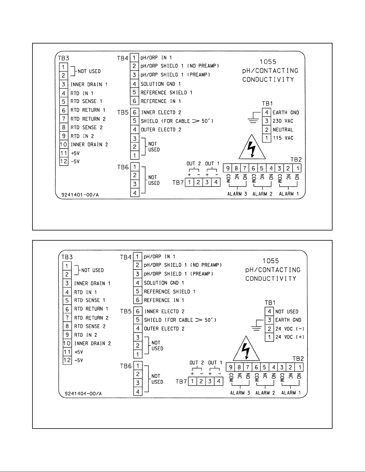
FIGURE 3-2. Wiring Connections for Solu Comp II Model 1055-01-10
(Panel Mount with 115/230 Vac Power)
FIGURE 3-3. Wiring Connections for Solu Comp II Model 1055-02-10
(Panel Mount with 24 Vdc Power)
Page 26
MODEL SOLU COMP II SECTION 3.0
WIRING
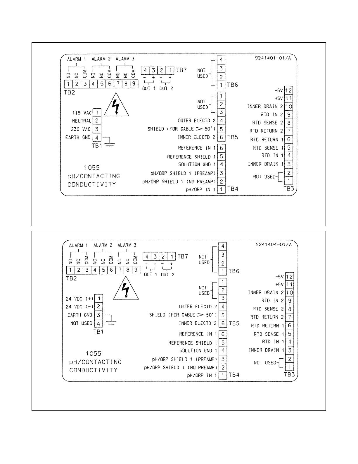
FIGURE 3-5. Wiring Connections for Solu Comp II Model 1055-02-11
(Surface/Pipe Mounting with 24 Vdc Power)
FIGURE 3-4. Wiring Connections for Solu Comp II Model 1055-01-11
(Surface/Pipe Mounting with 115/230 Vac Power)
17
Page 27
18
MODEL SOLU COMP II SECTION 3.0
WIRING
FIGURE 3-6. Panel Mount Wiring to Models 399-09-62, 400, 401, 402, 403, and 404.
DWG. NO. REV.
41055105 B
Page 28

MODEL SOLU COMP II SECTION 3.0
WIRING
19
FIGURE 3-7. Pipe/Wall Mount Wiring to Models 399-14, 400, 401, 402, 403, and 404.
DWG. NO. REV.
41055106 B
Page 29

20
MODEL SOLU COMP II SECTION 3.0
WIRING
FIGURE 3-8. Pipe/Wall Mount Wiring to Models 399VP-09, 400, 401, 402, 403, and 404.
DWG. NO. REV.
41055107 B
Page 30

MODEL SOLU COMP II SECTION 3.0
WIRING
21
FIGURE 3-9. Panel Mount Wiring to Models 399VP-09, 400, 401, 402, 403, and 404.
DWG. NO. REV.
41055108 B
Page 31

22
MODEL SOLU COMP II SECTION 3.0
WIRING
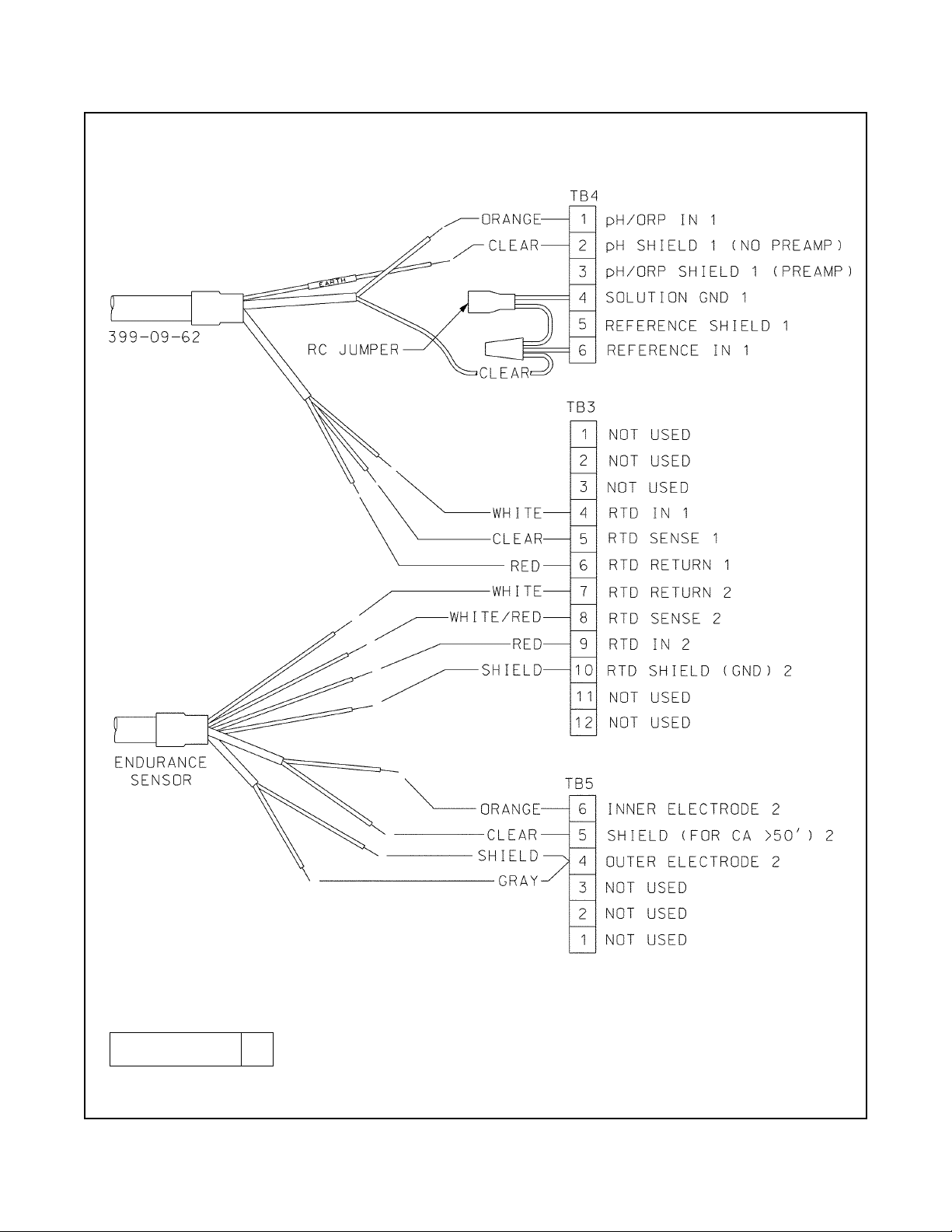
FIGURE 3-10. Pipe/Wall Mount Wiring to Models 399-09-62, 400, 401, 402, 403, and 404.
DWG. NO. REV.
41055109 B
Page 32

MODEL SOLU COMP II SECTION 3.0
WIRING
23
FIGURE 3-11. Panel Mount Wiring to Models 399-14, 400, 401, 402, 403, and 404.
DWG. NO. REV.
41055110 B
Page 33

24
MODEL SOLU COMP II SECTION 3.0
WIRING
FIGURE 3-12. Wiring Model 1055-11-22-32 to Models 399-09-62 and GP-1.
DWG. NO. REV.
40105536 C
Page 34

MODEL SOLU COMP II SECTION 3.0
WIRING
25
FIGURE 3-13. Wiring Model 1055-10-22-32 to Model 399-14
DWG. NO. REV.
40105559 E
FIGURE 3-14. Wiring Model 1055 to Model 320HP-58 and 400, 401, 402, 403, or 404
DWG. NO. REV.
41055112 C
Page 35

26
MODEL SOLU COMP II SECTION 4.0
DISPLAY AND OPERATION
SECTION 4.0
DISPLAY AND OPERATION
4.1 DISPLAY
4.2 KEYPAD
4.3 PROGRAMMING AND CALIBRATING THE SOLU COMP II - TUTORIAL
4.4 SECURITY
4.5 USING HOLD
4.1. DISPLAY
The Solu Comp II has a two-line display.
The display can be customized to meet
user requirements (see Section 5.11).
Figure 4-1 shows some of the displays
available during normal operation. View
A is the default screen for a dual sensor.
View B is the default screen for a single
sensor.
The Solu Comp II has information
screens that supplement the data in the
main display. Press or to view the
information screens. The last informa-
tion screen is the software version.
During calibration and programming,
key presses cause different displays to
appear. The displays are self-explanatory and guide the user step-by-step
through the procedure.
4.2 KEYPAD
Figure 4-2 shows the Solu Comp II keypad.
FIGURE 4-1. Displays During Normal Operation
Screen A shows pH measured by sensor 1 and conductivity measured by
sensor 2. Sensor 1 must always be pH, and sensor 2 must always be conductivity. Although Screen A is the most useful screen, other display
screens are possible. For example, Screen B shows data for sensor 1
(pH) only, and Screen C shows pH and conductivity, as well as temperature, measured by sensor 1 and 2.
FIGURE 4-2. Solu Comp II Keypad
Four arrow keys move the cursor around the screen. A blinking word or
numeral show the position of the cursor. The arrow keys are also used to
change the value of a numeral. Pressing ENTER stores numbers and settings and moves the display to the next screen. Pressing EXIT returns to
the previous screen without storing changes. Pressing MENU always
causes the main menu screen to appear. Pressing MENU followed by
EXIT causes the main display to appear.
Page 36

27
MODEL SOLU COMP II SECTION 4.0
DISPLAY AND OPERATION
4.3 PROGRAMMING AND CALIBRATING THE SOLU COMP II
- TUTORIAL
Setting up and calibrating the Solu Comp II is easy. The following tutorial
describes how to move around in the programming menus. For practice, the
tutorial also describes how to assign conductivity values to the 4 and 20 mA
outputs for sensor 1.
1. If the MENU screen (shown at the left) is not already showing, press
MENU. Calibrate is blinking, which means the cursor is on Calibrate.
2. To assign pH or conductivity values to current outputs, the Program sub-
menu must be open. Press . The cursor moves to Program (Program
blinking). Press ENTER. Pressing ENTER opens the Program sub-menu.
3. The Program sub-menu permits the user to set outputs, alarms, automatic or manual temperature compensation, and a security code. When
the sub-menu opens, Outputs is blinking, which means the cursor is on
Outputs. Press or (or any arrow key) to move the cursor around the
display. Move the cursor to >> and press ENTER to cause a second
screen with more program items to appear. There are three screens in the
Program menu. Pressing >> and ENTER in the third screen causes the
display to return to the first screen (Outputs, Alarms, Measurement).
4. For practice, assign pH values to the 4 and 20 mA outputs for sensor 1.
Move the cursor to Outputs and press ENTER.
5. The screen shown at left appears. The cursor is on Output Range (blinking). Output range is used to assign values to the low and high current outputs. Press ENTER.
6. The screen shown at left appears. The Solu Comp II has two outputs, output 1 and output 2. Move the cursor to the desired output and press
ENTER. For purposes of the example, choose Output 1.
7. The screen shown at left appears. Out1 S1 in the top line means output 1
(Out1) is assigned to sensor 1 (S1). Either output can be assigned to
either sensor (sensor and output assignments are made under the
Output Configure menu shown in step 5). Use the Out1 S1 Range?
screen to assign a pH value to the 4 mA output.
a. Use the arrow keys to change the pH to the desired value. Press or
to move the cursor from digit to digit. Press or to increase or
decrease the value of the digit. Holding or down causes the
numeral to continuously scroll up or down.
b. To move the decimal point, press or until the cursor is on the dec-
imal point. Press to move the decimal point to the right. Press to
move the decimal point to the left.
c. Press ENTER to store the setting.
8. The screen shown at left appears. Use this screen to assign a full scale
pH value to the 20 mA output. Use the arrow keys to change the pH to the
desired value. Press ENTER to store the setting.
9. The screen shown at left appears. To assign values to the low and high
currents for output 2, select Output 2 and follow the prompts.
10. To return to the main menu, press MENU. To return to the main display
press MENU then EXIT, or press EXIT repeatedly until the main display
appears. To return to the previous display press EXIT.
NOTE
To store values or settings, press ENTER before pressing EXIT.
CCaalliibbrraattee
Hold
Program Display
Calibrate Hold
PPrrooggrraamm
Display
OOuuttppuuttss
Alarms
Measurement >>
OOuuttppuutt RRaannggee
Output Configure
Output Range?
OOuuttppuutt11
Output2
Out1 S1 Range?
4mA
00
.00pH
Out1 S1 Range?
20mA
11
4.00pH
Output Range?
OOuuttppuutt11
Output2
Page 37

MODEL SOLU COMP II SECTION 4.0
DISPLAY AND OPERATION
1. If a security code has been programmed, pressing MENU causes the
security screen to appear.
2. Enter the three-digit security code.
3. If the entry is correct, the main menu screen appears. If the entry is incorrect, the Invalid Code screen appears. The Enter Security Code screen
reappears after 2 seconds.
Enter Security
Code
000000
Invalid Code
Calibrate
HHoolldd
Program Display
Hold Outputs and
Alarms?
YYeess
No
28
4.4 SECURITY
4.4.1 How the Security Code Works
Use the security code to prevent accidental or unwanted changes to program settings, displays, and calibration.
4.4.2 Bypassing the Security Code
Enter 555. The main menu will open.
4.4.3 Setting a Security Code
See Section 5.7.
4.5 USING HOLD
4.5.1 Purpose
The analyzer output is always proportional to measured pH or conductivity. To prevent unwanted alarms and
improper operation of control systems or dosing pumps, place the analyzer in hold before removing the sensor for
calibration and maintenance. Be sure to remove the analyzer from hold once
calibration is complete. During hold, both outputs remain at the last value. Once
in hold, the analyzer remains there indefinitely. While in hold, the screen
shown to the left appears periodically.
HHoolldd
4.5.2 Using the Hold Function
To choose a menu item, move the cursor to the item and press ENTER.
To store a number or setting, press ENTER.
1. Press MENU. The main menu screen appears. Choose Hold.
2. The Hold Outputs and Alarms ? screen appears. Choose Yes to place
the analyzer in hold. Choose No to take the analyzer out of hold.
3. The main display screen will appear.
Page 38

29
MODEL SOLU COMP II SECTION 5.0
PROGRAMMING THE ANALYZER
SECTION 5.0
PROGRAMMING THE ANALYZER
5.1 GENERAL
5.2 CHANGING STARTUP SETTINGS
5.3 CONFIGURING AND RANGING THE OUTPUTS
5.4 CONFIGURING ALARMS AND ASSIGNING SETPOINTS
5.5 SELECTING THE TYPE OF MEASUREMENT AND ACTIVATING SOLUTION
TEMPERATURE CORRECTION
5.6 CHOOSING TEMPERATURE UNITS AND MANUAL OR AUTOMATIC TEMPERATURE COMPENSATION
5.7 SETTING A SECURITY CODE
5.8 NOISE REJECTION
5.9 SINGLE SENSOR OR DUAL SENSOR INPUT
5.10 RESETTING FACTORY CALIBRATION AND FACTORY DEFAULT SETTINGS
5.11 SELECTING A DEFAULT SCREEN, LANGUAGE, AND SCREEN CONTRAST
5.1 GENERAL
This section describes how to do the following:
1. configure and assign values to the current outputs
2. configure and assign setpoints to the alarm relays
3. choose pH, ORP, redox, conductivity, resistivity, or TDS
4. choose temperature units and manual or automatic temperature mode
5. set a security code
6. tell the analyzer the frequency of the ac power (needed for optimum noise rejection)
7. tell the analyzer the number of sensors being used
8. reset the analyzer to factory calibration and default settings
9. select a default display screen
Default settings are shown in Table 5-1 on the following page. To change a default setting, refer to the section listed in the table. To reset default settings, see Section 5.10.
5.2 CHANGING STARTUP SETTINGS
When the Solu Comp II is powered up for the first time, startup screens appear. The screens prompt the user to
identify the number of sensors being used and whether pH, ORP, redox, conductivity, resistivity, or TDS is being
measured. If incorrect settings were entered at startup, enter the correct settings now. To change the number of
sensors refer to Section 5.9. To change the measurement, refer to Section 5.5.
FOR BEST RESULTS, ENTER THE NUMBER OF SENSORS BEING USED
(SECTION 5.9) AND WHETHER pH, ORP, REDOX, CONDUCTIVITY, RESISTIVITY, OR TDS IS BEING MEASURED (SECTION 5.5) BEFORE MAKING
OTHER PROGRAM SETTINGS.
Page 39

30
MODEL SOLU COMP II SECTION 5.0
PROGRAMMING THE ANALYZER
TABLE 5-1. DEFAULT SETTINGS
1. SENSOR-OUTPUT ASSIGNMENTS (pH, ORP, redox, conductivity, resistivity, or TDS is selected during Quick Start)
3. OUTPUT RANGES (pH, ORP, redox, conductivity, resistivity, or TDS is selected during Quick Start)
Measurement Range Section
pH 0 to 14 5.3
ORP/Redox -1400 to 1400 mV 5.3
Temperature 0 to 100°C 5.3
Resistivity 0.0 to 20 MΩ-cm 5.3
TDS 0 to 1000 ppm 5.3
Conductivity — 0.01/cm 0 to 10 µS/cm 5.3
Conductivity — 0.1/cm 0 to 100 µS/cm 5.3
Conductivity — 1.0/cm 0 to 1000 µS/cm 5.3
Conductivity — 10/cm 0 to 20 mS/cm 5.3
Sensor(s) Output 1 Output 2 Section
Single sensor pH/ORP/Redox Temperature 5.3 and 5.9
Dual sensor pH/ORP/Redox (sensor 1) Conductivity/Resistivity (sensor 2) 5.3 and 5.9
2. OTHER OUTPUT SETTINGS
Output Dampening 0 or 4 mA Mode Section
1 off 4 Linear 5.3
2 off 4 Linear 5.3
4. ALARM CONFIGURATION AND SETPOINTS
Alarm
1 2 3 Section
Assigned to Sensor 1 (pH, ORP) Sensor 2 (conductivity) (note 1) Fault 5.4
High or low High High (note 2) NA 5.4
Deadband 0 0 NA 5.4
Setpoint (pH) 14 (high); 0 (low) 14 (high); 0 (low) NA 5.4
Setpoint 1400 mV (high); -1400 (low) 1400 mV (high); -1400 (low) NA 5.4
(ORP/Redox)
Setpoint 1000 µS/cm (high); 0 (low) 1000 µS/cm (high); 0 (low) NA 5.4
(conductivity)
Setpoint 20 MΩ-cm (high); 0 (low) 20 MΩ-cm (high); 0 (low) NA 5.4
(resistivity)
Setpoint (TDS) 1000 ppm (high); 0 (low) 1000 ppm (high); 0 (low) NA 5.4
Note 1: For single sensor input, alarm 2 is assigned to sensor 1.
Note 2: For resistivity measurements, alarm is low.
Page 40

MODEL SOLU COMP II SECTION 5.0
PROGRAMMING THE ANALYZER
TABLE 5-1. DEFAULT SETTINGS (continued)
6. MISCELLANEOUS SETTINGS
Section
Language English 5.11
Hold off 4.5
Security code 000 (no security code) 5.7
ac power frequency 60 Hz 5.8
5. TEMPERATURE RELATED SETTINGS
Section
Units °C 5.6
Automatic temperature compensation (pH) On 5.6
Automatic temperature correction (conductivity) On 5.6
Solution temperature correction (pH) Off 5.5
Isopotential pH 7.00 5.5
Temperature correction (conductivity) neutral salt 5.5
Temperature slope 2%/°C 5.5
31
Page 41

32
MODEL SOLU COMP II SECTION 5.0
PROGRAMMING THE ANALYZER
5.3 CONFIGURING AND RANGING THE OUTPUTS.
5.3.1 Purpose
The Solu Comp II accepts input from a pH, ORP, or conductivity sensor and has two current outputs. This section
describes how to configure and range the outputs. CONFIGURE THE OUTPUTS FIRST.
1. Configuring an output means
a. Selecting either a 4-20 mA or 0-20 mA output,
b. Assigning a sensor and a measurement (pH, ORP, redox potential, conductivity, resistivity, or total dis-
solved solids [TDS]) to output 1 and output 2,
c. Turning on or turning off output current dampening,
d. Choosing a linear or logarithmic output.
2. Ranging the outputs means assigning values to the low (0 or 4 mA) and high (20 mA) outputs.
5.3.2 Definitions
1. CURRENT OUTPUTS. The analyzer provides either a continuous 4-20 mA or 0-20 mA output current directly
proportional to pH, ORP, redox potential, conductivity, resistivity, or TDS.
2. ASSIGNING OUTPUTS. Figure 5-1 shows the ways in which the outputs can be assigned.
3. DAMPEN. Output dampening smooths out noisy readings. It also increases the response time of the output.
With output dampening the time to reach 63% of final reading following a step change is 5 sec. Output dampening does not affect the response time of the display.
4. MODE. The current output can be made directly proportional to the displayed value (linear mode) or directly
proportional to the common logarithm of the displayed value (log mode).
FIGURE 5-1. Assigning Outputs 1 and 2
Page 42

MODEL SOLU COMP II SECTION 5.0
PROGRAMMING THE ANALYZER
5.3.3. Procedure: Configure Outputs.
To choose a menu item, move the cursor to the item and press ENTER.
To store a number or setting, press ENTER.
1. Press MENU. The main menu screen appears. Choose Program.
2. Choose Outputs.
3. Choose Output Configure.
4. Choose Output1 or Output2.
5. Choose Sensor1 (pH) or Sensor2 (conductivity). Either sensor can be
assigned to either output.
6. Choose Measurement or Temp. If the output selected was assigned to
Sensor 1, Measurement means pH, ORP, or redox. If the output selected was assigned to Sensor 2, Measurement means conductivity, resistivity, or TDS.
7. Make the appropriate settings:
a. Choose 4-20 mA or 0-20 mA.
b. Choose Yes or No for output dampening.
c. Choose Linear or Log output.
8. The display returns to the Output Config? screen. Select the other output or press EXIT to return to the previous screen. To return to the main
display, press MENU followed by EXIT.
5.3.4. Procedure: Assigning Values to the Low and High Current Outputs (Output Ranging)
To choose a menu item, move the cursor to the item and press ENTER.
To store a number or setting, press ENTER.
1. Press MENU. The main menu screen appears. Choose Program.
2. Choose Outputs.
3. Choose Output Range. Choose Output1 or Output2.
4. Make the appropriate settings.
a. Assign a value to the low current (0 mA or 4 mA) output.
b. Assign a value to the high current (20 mA) output.
5. The display returns to the Output Range screen. Select the other output
or press EXIT to return to the previous screen. To return to the main display, press MENU followed by EXIT.
Calibrate Hold
PPrrooggrraamm
Display
Output Config?
OOuuttppuutt11
Output2
OutM is for?
SSeennssoorr11
Sensor2
OutM is for?
MMeeaassuurreemmeenntt
Temp
Output Range
OOuuttppuutt CCoonnffiigguurree
OOuuttppuuttss
Alarms
Measurement >>
Calibrate Hold
PPrrooggrraamm
Display
OOuuttppuutt RRaannggee
Output Configure
OOuuttppuuttss
Alarms
Measurement >>
33
Page 43

34
Alarm relays are single pole-double throw (SPDT). When an alarm is activated, the coil is energized.
When an alarm activates, AL1, AL2, or AL3 (as appropriate) appears periodically in the display.
4. USP 24 ALARM. Any alarm, if assigned to sensor 2 (conductivity) can be configured as a USP 24 alarm. A
USP 24 alarm activates when the non-temperature-corrected conductivity (raw conductivity) of the water is
within a user-selectable percentage (safety range) of the USP 24 limit. For example, at 40°C the USP 24 limit
is 1.7 µS/cm. If the safety range is 10%, the USP 24 alarm activates when the raw conductivity exceeds 1.7 (0.1 x 1.7) or 1.53 µS/cm.
MODEL SOLU COMP II SECTION 5.0
PROGRAMMING THE ANALYZER
5.4 CONFIGURING ALARMS AND ASSIGNING SETPOINTS
5.4.1 Purpose
This section describes how to do the following:
1. assign an alarm relay to a sensor,
2. set the alarm logic to high or low,
3. assign values to the alarm setpoints,
4. set the alarm deadbands.
ALARM RELAYS MUST BE CONFIGURED BEFORE ASSIGNING SETPOINTS.
5.4.2 Definitions
1. ASSIGNING ALARMS. There are three alarms (AL1, AL2, and AL3). Alarms 1 and 2 can be assigned to any
sensor. For example, AL1 and AL2 can be assigned to sensor 1 with, perhaps, one alarm configured as a high
alarm and the other as a low alarm, and AL3 can be assigned to sensor 2. Alarm 3 can be assigned to either
sensor or used as a fault alarm. The fault alarm activates when a fault exists in a sensor or the analyzer.
2. FAULT ALARM. A fault condition exists when the Solu Comp II detects a problem with a sensor or with the analyzer that is likely to cause seriously erroneous readings. If Alarm 3 was programmed as a fault alarm, the
alarm 3 relay will activate. The word Fault will appear alternately in the display with the reading.
3. ALARM LOGIC, SETPOINTS, AND DEADBANDS. See Figures 5-2 and 5-3.
FIGURE 5-2. High Alarm Logic
The alarm activates when the pH exceeds the high
setpoint. The alarm remains activated until the reading
drops below the value determined by the deadband.
FIGURE 5-3. Low Alarm Logic
The alarm activates when the conductivity drops below the
low setpoint. The alarm remains activated until the reading
increases above the value determined by the deadband.
Page 44

35
MODEL SOLU COMP II SECTION 5.0
PROGRAMMING THE ANALYZER
5.4.3 Procedure: Configuring Alarms
To choose a menu item, move the cursor to the item and press ENTER.
To store a number or setting, press ENTER.
1. Press MENU. The main menu screen appears. Choose Program.
2. Choose Alarms.
3. Choose Alarm Configure.
4. Choose Alarm 1 (AL1), Alarm 2 (AL2), or Alarm 3 (AL3).
5. For AL1 or AL2
a. Choose Sensor 1 (pH) or Sensor 2 (conductivity).
b. Choose Measurement or Temp.
c. Choose High, Low or USP 24. USP 24 appears only if Sensor 2 was
selected.
d. Set the alarm Deadband.
6. The display returns to the Alarm Configure? screen. Select another
alarm or press EXIT to return to the previous screen. To return to the main
display, press MENU followed by EXIT.
7. For AL3
a. Choose Sensor1 (pH), Sensor2 (conductivity), or Fault.
b. For sensor 1 or 2, choose Measurement or Temp.
c. Choose High, Low or USP 24. USP 24 appears only if Sensor 2 was
selected. Set the deadband.
d. Choosing Fault means AL3 will activate when a sensor or analyzer
fault exists. There is no user setting to make.
8. The display returns to the Alarm Configure? screen. Select another
alarm or press EXIT to return to the previous screen. To return to the main
display, press MENU followed by EXIT.
Calibrate Hold
PPrrooggrraamm
Display
Alarm Setpoints
AAllaarrmm CCoonnffiigguurree
Alarm Config?
AALL11
AL2 AL3
AL1 is for?
SSeennssoorr11
Sensor2
AL1 S1 is for?
MMeeaassuurreemmeenntt
Temp
Outputs
AAllaarrmmss
Measurement >>
AL3 is for?
FFaauulltt
Sensor1 Sensor2
Page 45

36
MODEL SOLU COMP II SECTION 5.0
PROGRAMMING THE ANALYZER
5.4.4 Procedure: Programming Alarm Setpoints
To choose a menu item, move the cursor to the item and press ENTER.
To store a number or setting, press ENTER.
1. Press MENU. The main menu screen appears. Choose Program.
2. Choose Alarms.
3. Choose Alarm Setpoints.
4. Choose Alarm 1 (AL1), Alarm 2 (AL2), or Alarm 3 (AL3).
5. The display shows the alarm selected (AL1) and the configuration. The
alarm is for Sensor 1 (S1), and the logic is high. Use the arrow keys to
change the alarm setpoint.
6. If the alarm is USP 24, the display shows the alarm selected and the USP
safety margin. Change the safety margin to the desired value.
7. The display returns to the Select Alarm? screen. Select another alarm or
press EXIT to return to the previous screen. To return to the main display,
press MENU followed by EXIT.
Calibrate Hold
PPrrooggrraamm
Display
AAllaarrmm SSeettppooiinnttss
Alarm Configure
Select Alarm?
AALL11
AL2 AL3
AL1 S2 Setpoint?
USP24
11
0% Safety
AL1 S1 Setpoint?
High
11
4.00pH
Outputs
AAllaarrmmss
Measurement >>
Page 46

37
MODEL SOLU COMP II SECTION 5.0
PROGRAMMING THE ANALYZER
5.5 SELECTING THE TYPE OF MEASUREMENT AND ACTIVATING SOLUTION
TEMPERATURE CORRECTIONS
5.5.1 Purpose
This section describes how to do the following:
1. Program the Solu Comp II to measure pH, ORP, redox potential, conductivity, resistivity, or total dissolved
solids.
2. Enable or disable glass impedance fault.
3. Select a solution temperature correction for pH.
4. Change the analyzer pH isopotential point.
5. Select a solution temperature correction for conductivity.
5.5.2 Definitions — pH/ORP
1. ORP. ORP is oxidation-reduction potential. It is the voltage difference between a noble metal (usually plat-
inum) indicator electrode and a silver/silver chloride reference electrode.
2. REDOX. Redox is redox potential. Redox potential is measured the same way as ORP. The sign of the redox
potential is the negative of ORP.
3. SIGN CONVENTION. The ORP of a solution of 0.1 M iron (II) ammonium sulfate and 0.1 M iron (III) ammoni-
um sulfate in 1 M sulfuric acid is positive. The redox potential is negative.
4. GLASS IMPEDANCE FAULT. The Solu comp II can be used with pH sensors having advanced diagnostic fea-
tures, which permit the continuous determination of glass and reference electrode impedance. When the analyzer detects low glass impedance, indicating a broken or cracked glass membrane, it automatically displays
a fault message. If the Solu Comp II is to be used with non-glass pH electrodes, the glass impedance fault
should be disabled.
5. SOLUTION TEMPERATURE CORRECTION. The pH of a solution, particularly an alkaline one, is a function
of temperature. If the temperature changes, so does the pH, even though the concentration of the acid or base
causing the pH remains constant. Solution temperature compensation converts the pH at the measurement
temperature to the pH at a reference temperature. The Solu Comp II corrects the pH to a reference temperature of 25°C.
For an accurate solution temperature correction, the exact composition of the solution must be known. The
Solu Comp II has built-in temperature corrections for high purity water and for dilute solutions of a strong base.
The analyzer also accepts a custom correction.
6. CUSTOM TEMPERATURE CORRECTION. The custom temperature correction has units of ∆pH/°C. The
example shows how the analyzer uses the custom correction. Suppose the pH of the solution being measured
decreases 0.022 units for every Celsius degree rise in temperature. The temperature correction is -
0.022pH/°C. If the pH at 20°C is 8.95, the corrected pH (at 25°C) is 8.95 + (-0.022)(25 - 20) or 8.84.
7. ISOPOTENTIAL pH. The isopotential pH is the pH at which the cell voltage (the cell is the pH electrode, ref-
erence electrode, and solution being measured) is independent of temperature. Most pH cells have isopotential pH reasonably close to 7.00, so the Solu Comp II assumes the cell isopotential pH is 7.00. However, certain specialized electrodes have isopotential pH different from 7.00.
NOTE
Do NOT change the isopotential pH of the transmitter unless you are thoroughly
familiar with the role of sensor and analyzer isopotential point in pH measurement, OR the sensor operating instructions specifically state the isopotential pH
is a value other than pH 7.00.
Page 47

MODEL SOLU COMP II SECTION 5.0
PROGRAMMING THE ANALYZER
5.5.3 Definitions — conductivity/resistivity
1. NEUTRAL SALT CORRECTION. Neutral salt temperature correction is appropriate for most applications
involving natural and treated waters in which neutral salts are primarily responsible for the conductivity. It is
NOT suitable if the sample is a dilute acid or base. The neutral salt correction programmed into the Solu Comp
II takes into account the contribution of water to the overall conductivity (or resistivity). Therefore, the neutral
salt works for high purity water as well as for waters having higher conductivity. The correction algorithm assumes the salt is sodium chloride. Because the change in the conductivity of sodium chloride solutions
with temperature is similar to most other aqueous salt solutions, the correction is suitable for most applications.
The correction applies between 0 and 100°C, and the reference temperature is 25°C.
2. LINEAR TEMPERATURE COEFFICIENT OR TEMPERATURE SLOPE. The change in the conductivity of
most electrolyte solutions having conductivity greater than about 5 µS/cm at 25°C can be expressed by the
the following equation:
C25=
C
t
1+ a(t - 25)
In the equation, C
25
is the conductivity at 25°C, Ctis the conductivity at t°C, and a is the linear temperature
coefficient. The linear temperature coefficient, or temperature slope, has units of %/°C. In the equation, the
temperature coefficient is expressed as a decimal fraction. The linear temperature coefficient depends to
some extent on both the temperature and concentration of the salt solution. The temperature coefficient also
varies from salt to salt.
For maximum accuracy, the temperature coefficient must be appropriate for the salt or salts in solution, their
concentration, and the temperature. Frequently, the relationship must be determined by experiment.
Fortunately, for most dilute neutral electrolyte solutions, a linear temperature coefficient of 2.00%/°C (0.0200)
is appropriate. The table gives typical ranges for different dilute electrolyte solutions.
Slope (%/°C)
Neutral salts 1.8 - 2.2
Acids and acid salts 1.0 - 1.6
Bases and basic salts 1.6 - 3.0
High purity water Use neutral salt correction
3. CATION TEMPERATURE CORRECTION. Cation conductivity, sometimes called acid conductance, is used in
steam power plants to measure salt contamination in boiler feedwater and steam. The Solu Comp II automatically corrects for the variation in the conductivity of extremely dilute hydrochloric acid with temperature and
displays the conductivity at 25°C. The correction is valid to 100°C, so the Solu Comp II can be used for
degassed cation conductivity measurements. Cation conductivity temperature correction also applies to semiconductor etch rinse baths, which contain trace amounts of acids.
4. RAW. Raw conductivity is the conductivity of the sample at the measurement temperature.
5. TDS. TDS is total dissolved solids. The Solu Comp II calculates TDS (in ppm) by multiplying the conductivity
(corrected to 25°C using a temperature coefficient of 2%/°C) by 0.65.
38
Page 48

MODEL SOLU COMP II SECTION 5.0
PROGRAMMING THE ANALYZER
5.5.4 Procedure.
To choose a menu item, move the cursor to the item and press ENTER.
To store a number or setting, press ENTER.
1. Press MENU. The main menu screen appears. Choose Program.
2. Choose Measurement.
3. Choose Sensor 1 (pH) or Sensor 2 (conductivity). For a single input con-
figuration, the Sensor 1 Sensor 2 screen does not appear.
If you chose Sensor 1, go to step 4.
If you chose Sensor 2, go to step 11.
4. For Sensor 1, choose pH, Redox, or ORP.
If you chose pH, do steps 5 through 9.
If you chose ORP or Redox, do step 10.
5. Choose NO if the pH sensing electrode is NOT a glass electrode.
6. Choose Soln Temp Corr or Sensor Isoptntl.
7. For Soln Temp Corr, choose Off, UltraPure, HighpH, or Custom. For
Custom, enter the desired temperature coefficient.
8. For Sensor Isoptntl, enter the desired sensor isopotential pH. Do not
change the sensor isopotential pH unless the sensor is known to have an
isopotential pH different from 7.00.
9. The display returns to the screen shown in step 3. Choose Sensor 2
(conductivity) and follow the prompts. See step 11.
10. If Redox or ORP was selected, there are no further settings to make. The
display returns to the screen shown in step 3. Choose Sensor 2 (conductivity) and follow the prompts. See step 11.
11. For Sensor 2, choose Cond (conductivity), Resistivity, or TDS (total dis-
solved solids).
If you chose Cond or Resistivity, go to step 12.
If you chose TDS, go to step 14.
12. Choose NeutSalt, Slope, Cation, or Raw. For Slope, enter the desired
temperature coefficient in %/°C.
13. The display returns to the screen shown in step 3. Press EXIT to return to
the previous screen. To return to the main display, press MENU followed
by EXIT.
14. If TDS was selected, there are no further settings to make.The display
returns to the screen shown in step 3. Press EXIT to return to the previous screen. To return to the main display, press MENU followed by EXIT.
Calibrate Hold
PPrrooggrraamm
Display
Config?
SSeennssoorr11
Sensor2
S2 Temp Corr?
NNeeuuttSSaalltt
Other
S1Measure?
ppHH
Redox ORP
S2 Measure?
CCoonndd
TDS Resistivity
S1 SolnTempCorr?
OOffff
Ultrapure >>
Sensor Isoptntl
S1:
00
7.00pH
S1 Glass Fault
Enable?
YYeess
No
Outputs Alarms
MMeeaassuurreemmeenntt
>>
SSoollnn TTeemmpp CCoorrrr
Sensor Isoptntl
39
Page 49

40
MODEL SOLU COMP II SECTION 5.0
PROGRAMMING THE ANALYZER
5.6 CHOOSING TEMPERATURE UNITS AND MANUAL OR AUTOMATIC TEMPERATURE
COMPENSATION
5.6.1 Purpose
This section describes how to do the following:
1. Choose temperature display units (°C or °F).
2. Choose automatic or manual temperature compensation for pH.
3. Choose automatic or manual temperature correction for conductivity/resistivity.
4. Enter a temperature for manual temperature compensation.
5.6.2 Definitions — pH
1. AUTOMATIC TEMPERATURE COMPENSATION — pH. The analyzer uses a temperature-dependent factor
to convert measured cell voltage to pH. In automatic temperature compensation, the analyzer measures the
temperature and automatically calculates the correct conversion factor. For maximum accuracy, use automatic temperature compensation.
2. MANUAL TEMPERATURE COMPENSATION — pH. In manual temperature compensation, the analyzer con-
verts measured voltage to pH using the temperature entered by the user. It does not use the actual process
temperature. Do NOT use manual temperature compensation unless the process temperature varies no more
than about ±2°C or the pH is between 6 and 8. Manual temperature compensation is useful if the sensor temperature element has failed and a replacement sensor is not available.
5.6.3 Definitions — Conductivity/Resistivity
1. AUTOMATIC TEMPERATURE CORRECTION — CONDUCTIVITY. The conductivity of an electrolyte solution
depends strongly on temperature. To allow comparison among measurements made at different temperatures,
conductivity and resistivity measurements are usually converted to the value at 25°C. The Solu Comp II performs the correction automatically using a neutral salt, dilute acid, or linear temperature coefficient algorithm.
See Section 5.5.3 for more information.
2. MANUAL TEMPERATURE CORRECTION — CONDUCTIVITY. In manual temperature compensation, the
analyzer converts measured conductivity (or resistivity) to the value at 25°C using the temperature entered by
the user. It does not use the actual process temperature.
Page 50

41
MODEL SOLU COMP II SECTION 5.0
PROGRAMMING THE ANALYZER
5.7 SETTING A SECURITY CODE
5.7.1 Purpose.
This section describes how to set a security code. The security code prevents program and calibration settings
from accidentally being changed. Refer to Section 4.4 for additional information.
5.7.2 Procedure.
To choose a menu item, move the cursor to the item and press ENTER.
To store a number or setting, press ENTER.
1. Press MENU. The main menu screen appears. Choose Program.
2. Choose >>, then Security.
3. Enter a three digit security code. The security code takes effect two minutes after the last key stroke.
4. The display returns to the security menu screen. Press EXIT to return to
the previous screen. To return to the main display, press MENU followed
by EXIT.
Calibrate Hold
PPrrooggrraamm
Display
Temp
SSeeccuurriittyy
#Sensors >>
Outputs Alarms
Measurement
>>>>
5.6.4 Procedure.
To choose a menu item, move the cursor to the item and press ENTER.
To store a number or setting, press ENTER.
1. Press MENU. The main menu screen appears. Choose Program.
2. Choose >>.
3. Choose Temp.
4. Choose °C/F to change temperature units. Choose Live/Manual to turn
on (Live) or turn off (Manual) automatic temperature compensation.
a. If °C/F is chosen, select °C or °F in the next screen.
b. If Live/Manual is chosen, select Live or Manual for sensor 1 (pH) in
the next screen.
c. If Manual is chosen, enter the temperature in the next screen. The
temperature entered in this step will be used in all subsequent measurements, no matter what the process temperature is.
d. The display will return to the Live/Manual screen for sensor 2 (con-
ductivity). Make the desired selections for sensor 2.
Calibrate Hold
PPrrooggrraamm
Display
Config Temp?
°
CC//FF
Live/Manual
TTeemmpp
Security
#Sensors >>
Outputs Alarms
Measurement
>>>>
Page 51

MODEL SOLU COMP II SECTION 5.0
PROGRAMMING THE ANALYZER
5.8 NOISE REJECTION
5.8.1 Purpose.
For maximum noise rejection, the frequency of the ac power must be entered in the analyzer.
5.8.2. Procedure.
To choose a menu item, move the cursor to the item and press ENTER.
To store a number or setting, press ENTER.
1. Press MENU. The main menu screen appears. Choose Program.
2. Choose >>.
3. Choose >>.
4. Choose Noise Rejection.
5. Enter the mains frequency, 50 Hz or 60 Hz.
6. The display returns to the Noise Rejection screen. To return to the main
menu, press EXIT. To return to the main display, press MENU followed by
EXIT.
5.9 SINGLE SENSOR OR DUAL SENSOR INPUT
5.9.1 Purpose
The Solu Comp II accepts input from a single sensor or from two sensors. This section describes how to program
the analyzer for single or dual sensors. COMPLETE THIS SECTION BEFORE DOING OTHER PROGRAMMING.
5.9.2 Procedure.
To choose a menu item, move the cursor to the item and press ENTER.
To store a number or setting, press ENTER.
1. Press MENU. The main menu screen appears. Choose Program.
2. Choose >>.
3. Choose #Sensors.
4. Choose One or Two. Choosing One configures the analyzer as a pH analyzer. Conductivity cannot be selected for single measurement.
5. The display returns to the # Sensors screen. To return to the main menu,
press MENU. To return to the main display, press MENU followed by
EXIT.
Calibrate Hold
PPrrooggrraamm
Display
NNooiissee RReejjeeccttiioonn
ResetAnalyzer >>
OOuuttppuuttss
Alarms
Measurement >>
TTeemmpp
Security
#Sensors >>
# of sensors?
One
ΤΤωωοο
OOuuttppuuttss
Alarms
Measurement >>
TTeemmpp
Security
#Sensors >>
Calibrate Hold
PPrrooggrraamm
Display
42
Page 52

43
MODEL SOLU COMP II SECTION 5.0
PROGRAMMING THE ANALYZER
5.11 SELECTING A DEFAULT SCREEN, LANGUAGE, AND SCREEN CONTRAST
5.11.1 Purpose
This section describes how to do the following:
1. set a default display screen
The default display screen is the screen shown during normal operation. The Solu Comp II allows the user to
choose from a large number of screens. Which screens are available depends on how the analyzer was configured. The following is an explanation of the abbreviations used in the screens.
In the display:
i. S means sensor. S1 is sensor 1, and S2 is sensor 2. If neither S1 nor S2 appears, then the analyzer has
been configured for a single sensor input.
ii. G is glass electrode impedance, and R is reference electrode impedance.
2. select a language
3. change the screen contrast
5.10 RESETTING FACTORY CALIBRATION AND FACTORY DEFAULT SETTINGS
5.10.1 Purpose.
This section describes how to re-install factory calibration and default values. The process also clears all fault messages and returns the display to the first quick start screen.
5.10.2. Procedure.
To choose a menu item, move the cursor to the item and press ENTER.
To store a number or setting, press ENTER.
1. Press MENU. The main menu screen appears. Choose Program.
2. Choose >>.
3. Choose >>.
4. Choose ResetAnalyzer.
5.
Choose Yes or No. If Yes is selected, previous settings are cleared and
the Quick Start Menu appears.
Noise Rejection
ResetAnalyzer >>
Load factory
settings?
YYeess
No
OOuuttppuuttss
Alarms
Measurement >>
TTeemmpp
Security
#Sensors >>
Calibrate Hold
PPrrooggrraamm
Display
Page 53

44
MODEL SOLU COMP II SECTION 5.0
PROGRAMMING THE ANALYZER
5.11.4 Procedure: Changing Screen Contrast
1. Press MENU. The main menu screen appears. Choose Display.
2. Choose Contrst.
3. Press or to increase or decrease the screen contrast. As contrast
increases, the number increases.
4. The display returns to the screen shown in step 2. To return to the main
menu, press MENU. To return to the main display, press MENU followed
by EXIT.
Calibrate Hold
Program
DDiissppllaayy
Default Display
Units
CCoonnttrrsstt
Screen Contrast:
5500
5.11.2 Procedure: Selecting a Display Screen
1. Press MENU. The main menu screen appears. Choose Display.
2. Choose Default Display.
3. Press or until the desired display appears. Press ENTER. For an
explanation of abbreviations, see Section 5.11.1.
4. The display returns to the screen in step 2. To return to the main menu,
press MENU. To return to the main display, press MENU followed by
EXIT.
Calibrate Hold
Program
DDiissppllaayy
DDeeffaauulltt DDiissppllaayy
Language Contrst
5.11.3 Procedure: Choosing a Language
1. Press MENU. The main menu screen appears. Choose Display.
2. Choose Language.
3. Choose English, Français, Español, Deutsch, Italiano, or Portugues.
4. The display returns to the screen in step 2. To return to the main menu,
press MENU. To return to the main display, press MENU followed by
EXIT.
Calibrate Hold
Program
DDiissppllaayy
Default Display
LLaanngguuaaggee
Contrast
EEnngglliisshh
Fran ais
Espa ol >>
To choose a menu item, move the cursor to the item and press ENTER.
To store a number or setting, press ENTER.
Page 54

45
MODEL SOLU COMP II SECTION 6.0
CALIBRATION
SECTION 6.0
CALIBRATION
6.1 INTRODUCTION
6.2 CALIBRATING TEMPERATURE
6.3 AUTO CALIBRATION - pH
6.4 MANUAL CALIBRATION - pH
6.5 STANDARDIZATION - pH
6.6 ENTERING A KNOWN SLOPE - pH
6.7 ORP CALIBRATION
6.8 CALIBRATING AN IN-SERVICE SENSOR - CONDUCTIVITY
6.9 PLACING A NEW SENSOR IN SERVICE - CONDUCTIVITY
6.10 CALIBRATING THE ANALYZER - CONDUCTIVITY
6.1 INTRODUCTION
The Calibrate Menu allows the user to calibrate sensor 1 (pH or ORP) and sensor 2 (conductivity). The temperature response of each sensor can also be calibrated.
For pH sensors, two-point buffer calibration is standard. In auto calibration the analyzer calculates the pH of the
buffer from the nominal value entered by the user and does not accept calibration data until readings are stable.
In manual calibration the user enters buffer values and judges when readings are stable. The pH reading can also
be standardized, that is, forced to match the reading from a referee instrument. Finally, if the user knows the electrode slope (at 25°C), he can enter it directly.
The ORP calibration is a single-point calibration against an ORP standard.
For conductivity measurements, several types of calibration are possible. The sensor and analyzer can be calibrated as a unit against a solution having an accurately known conductivity, or they can be calibrated against a
referee instrument. The analyzer and sensor can also be calibrated separately. The analyzer is calibrated against
a known resistance. The sensor cell constant can be measured independently and the results entered directly into
the Solu Comp II.
Page 55

46
MODEL SOLU COMP II SECTION 6.0
CALIBRATION
6.2 CALIBRATING TEMPERATURE
6.2.1 Purpose
Temperature is important in the measurement of pH, ORP, and conductivity (or resistivity) for different reasons.
Temperature affects the measurement of pH in three ways.
1. The analyzer uses a temperature dependent factor to convert measured cell voltage to pH. Normally, a slight
inaccuracy in the temperature reading is unimportant unless the pH reading is significantly different from 7.00.
Even then, the error is small. For example, at pH 12 and 25°C, a 1°C error produces a pH error less than ±0.02.
2. During auto calibration, the Solu Comp II recognizes the buffer being used and calculates the actual pH of the
buffer at the measured temperature. Because the pH of most buffers changes only slightly with temperature,
reasonable errors in temperature do not produce large errors in the buffer pH. For example, a 1°C error causes at most an error of ±0.03 in the calculated buffer pH.
3. The Solu Comp II can be programmed to calculate and display pH at a reference temperature (25°C). The
maximum change in solution pH with temperature is about ±0.04 pH/°C, so a 1°C temperature error does introduce a small error. However, the major source of error in solution temperature compensation is using an incorrect temperature coefficient.
Temperature affects the measurement of ORP in a complicated fashion that is best determined empirically.
Conductivity is a strong function of temperature. Therefore, to compare conductivity measurements made at different temperatures, conductivity must be converted to the value at a reference temperature, usually 25°C. The
conductivity of most dilute electrolyte solutions changes about 2%/°C, so a small error in temperature is of little
consequence. The conductivity of high purity water changes about 5%/°C or more, so small errors in temperature
can lead to substantial errors in the corrected conductivity. Although accurate temperature measurement is important, often the major error in the corrected conductivity arises from the use of an incorrect temperature coefficient.
Without calibration the accuracy of the temperature measurement is about ±0.4°C. Calibrate the sensor/analyzer
unit if
1. ±0.4°C accuracy is not acceptable
2. the temperature measurement is suspected of being in error. Calibrate temperature by making the analyzer
reading match the temperature measured with a standard thermometer.
Page 56

47
6.2.2 Procedure
1. Remove the sensor from the process. Place it in an insulated container of water along with a calibrated thermometer. Submerge at least the bottom two inches of the sensor. Stir continuously.
2. Allow the sensor to reach thermal equilibrium. For some sensors, the time constant for a change in temperature is 5 min., so it may take as long as 30 min. for temperature equilibration.
3. If the sensor cannot be removed from the process, measure the temperature of a flowing sample taken from
a point as close to the sensor as possible. Let the sample continuously overflow an insulated container holding a calibrated thermometer.
4. Change the Solu Comp II display to match the calibrated thermometer using the procedure below.
MODEL SOLU COMP II SECTION 6.0
CALIBRATION
a. Press MENU. The main menu screen appears. Choose Calibrate.
b. Choose Sensor1 (pH) or Sensor2 (conductivity).
c. Choose Temp.
d. If the analyzer was programmed in Section 5.6 to use the actual process
temperature, the screen at left will appear. To calibrate the temperature,
change the number in the second line to match the temperature measured with the standard thermometer. Press ENTER. Go to step f.
If the calibration temperature is more than 2 or 3°C different from the live
reading, see Section 8.3.1 or Section 8.4.2.
If the analyzer was programmed to use a temperature entered by the
user, go to step e.
e. The screen at left will appear if the analyzer was programmed for manu-
al temperature compensation. Change the temperature to the desired
value, then press ENTER. The analyzer will use the temperature entered
in this step in all measurements and calculations, no matter what the true
temperature is.
f. The screen at left will appear. Press EXIT.
g. Choose the other sensor and calibrate its temperature response.
h. To return to the main display, press MENU followed by EXIT.
CCaalliibbrraattee
Hold
Program Display
CalSensor1?
Measurement
TTeemmpp
CalSensor1?
Measurement
TTeemmpp
Calibrate?
Sensor1
SSeennssoorr22
Calibrate?
SSeennssoorr11
Sensor2
Live 25.0°C
CalS1
++
25.0°C
ManualTemp?
S1: +25.0°C
Page 57

MODEL SOLU COMP II SECTION 6.0
CALIBRATION
6.3 AUTO CALIBRATION — pH
6.3.1 Purpose
1. New sensors must be calibrated before use. Regular recalibration is also necessary.
2. Use auto calibration instead of manual calibration. Auto calibration avoids common pitfalls and reduces errors.
6.3.2 Definitions
1. AUTO CALIBRATION. The analyzer recognizes the buffers and uses temperature-corrected pH values in the
calibration. The table lists the buffers the Solu Comp II recognizes.
Note 1: NIST is National Institute of Standards, DIN is Deutsche Institute für
Normung, JSI is Japan Standards Institute, and BSI is British Standards
Institute.
Note 2: pH 7 buffer is not a standard buffer. It is a popular commercial buffer
in the United States.
The Solu Comp II also measures noise and drift and does not accept calibration data until readings are stable. Calibration data will be accepted as soon as the pH reading is constant to within 0.02 units for 10 seconds. The stability settings cannot be changed.
2. SLOPE AND OFFSET. Once the Solu Comp II successfully completes the calibration, it calculates and
displays the calibration slope and offset. The slope is
reported as the slope at 25°C. Figure 6-1 defines the
terms.
6.3.3 Procedure
1. Obtain two buffer solutions. Ideally the buffer pH values should bracket the range of pH values to be measured.
2. Remove the sensor from the process liquid. If the
process and buffer temperatures are appreciably different, place the sensor in a container of tap water at
the buffer temperature. Do not start the calibration until
the sensor has reached the buffer temperature. Thirty
minutes is usually adequate.
3. Calibrate the sensor by using the procedure on the following page.
pH at 25°C Standard(s)
(nominal pH)
1.68 NIST, DIN 19266, JSI 8802, BSI (see note 1)
3.56 NIST, BSI
3.78 NIST
4.01 NIST, DIN 19266, JSI 8802, BSI
6.86 NIST, DIN 19266, JSI 8802, BSI
7.00 (see note 2)
7.41 NIST
9.18 NIST, DIN 19266, JSI 8802, BSI
10.01 NIST, JSI 8802, BSI
12.45 NIST, DIN 19266
FIGURE 6-1. Calibration Slope and Offset
48
Page 58

49
MODEL SOLU COMP II SECTION 6.0
CALIBRATION
a. Press MENU. The main menu screen appears. Choose Calibrate.
b. Choose Sensor1 (pH sensor).
c. Choose Measurement.
d. Choose BufferCal.
e. Choose Auto.
f. Choose Buffer1.
g. Rinse the sensor with water and place it in buffer 1. Be sure the glass bulb
and reference junction are completely submerged. Swirl the sensor.
h. The screen at left is displayed until the reading is stable (<0.02 pH change
in 10 sec). When the reading is stable, the screen in step i appears. To
bypass automatic stabilization, press ENTER at any time.
i. The top line shows the actual reading (S1Live). The analyzer also identifies
the buffer and displays the nominal buffer value (buffer pH at 25°C). If the
displayed value is not correct, press or to select the correct value. The
nominal value will change, for example, from 7.01 pH to 6.86 pH. Press
ENTER.
j. The screen shown at left appears.
k. Remove the sensor from buffer 1, rinse it with water, and place it in buffer
2. Swirl the sensor. Choose Buffer2.
l. The screen at left is displayed until the reading is stable (<0.02 pH change
in 10 sec). When the reading is stable, the screen in step m appears. To
bypass automatic stabilization, press ENTER at any time.
m. The top line shows the actual reading (S1Live). The analyzer also identifies
the buffer and displays the nominal buffer value (buffer pH at 25°C). If the
displayed value is not correct, press or to select the correct value. The
nominal value will change, for example, from 7.01 pH to 6.86 pH. Press
ENTER to accept the nominal value.
n. If the calibration was successful, the analyzer will display the offset and
slope (at 25°C). The display will return to the screen in step b. Choosing
Sensor2 (conductivity sensor) will permit the conductivity measurement to
be calibrated.
o. If the slope is out of range (less than 45 mV/pH or greater than 60 mV/pH),
an error screen appears. The display then returns to step f. Repeat the calibration.
p. To return to the main display, press MENU followed by EXIT.
CCaalliibbrraattee
Hold
Program Display
Calibrate?
SSeennssoorr11
Sensor2
CalSensor1?
MMeeaassuurreemmeenntt
Temp
S1BufferCal?
AAuuttoo
Manual
S1AutoCal?
BBuuffffeerr11
Buffer2
S1AutoCal?
BBuuffffeerr11
Buffer2
S1 Standardize
Slope
BBuuffffeerrCCaall
S1Live 7.00pH
AutoBuf1
WWaaiitt
S1Live 7.00pH
AutoBuf1
77..0011ppHH
S1Live 7.00pH
Buf2
WWaaiitt
S1Live 7.00pH
AutoBuf2
77..0011ppHH
S1Offset 6mV
Slope 59.16 25
°C
Calibration
Error
S1AutoCal?
Buffer1
BBuuffffeerr22
Page 59

50
MODEL SOLU COMP II SECTION 6.0
CALIBRATION
6.4 MANUAL CALIBRATION — pH
6.4.1 Purpose
1. New sensors must be calibrated before use. Regular recalibration is also necessary.
2. Use manual calibration if non-standard buffers are being used; otherwise, use auto calibration. Auto calibration avoids common pitfalls and reduces errors.
6.4.2 Definitions
1. MANUAL CALIBRATION. In auto calibration the analyzer recognizes the buffer and uses the temperature-corrected pH value in the calibration. The analyzer also measures noise and drift and does not accept calibration
data until readings are stable. During manual calibration, the user must judge when readings are stable and
look up and enter the buffer values.
2. SLOPE AND OFFSET. Once the Solu Comp II successfully completes the calibration, it calculates and displays the calibration slope and offset. The slope is reported as the slope at 25ºC. Figure 6-1 defines the terms.
6.4.3 Procedure
1. Obtain two buffer solutions. Ideally, the buffer pHs should bracket the range of pH values to be measured. Also
obtain a thermometer. The pH of most buffer solutions is a function of temperature. To calibrate the sensor
properly, the pH of the buffer at the measurement temperature must be entered in the analyzer.
2. Remove the sensor from the process liquid. If the process and buffer temperature are appreciably different,
place the sensor in a container of tap water at the buffer temperature. Do not start the calibration until the sensor has reached the buffer temperature. Thirty minutes is usually adequate.
3. Calibrate the sensor using the procedure on the following page.
Page 60

51
MODEL SOLU COMP II SECTION 6.0
CALIBRATION
a. Press MENU. The main menu screen appears. Choose Calibrate.
b. Choose Sensor1 (pH sensor).
c. Choose Measurement.
d. Choose BufferCal.
e. Choose Manual.
f. Choose Buffer1.
g. Rinse the sensor with water and place it in buffer 1. Be sure the glass bulb
and junction are completely submerged. Swirl the sensor. Also place a
thermometer in the buffer. Press ENTER
h. The top line shows the actual buffer reading (S1 Live). Wait until the read-
ing is stable, then note the temperature. Change the pH in the second line
to the pH of the buffer at the measured temperature. Press ENTER.
i. The screen at left appears. Choose Buffer2. Rinse the sensor and ther-
mometer with water and place them in buffer 2. Be sure the bulb and junction are submerged. Swirl the sensor.
j. The top line shows the actual buffer reading (S1 Live). Wait until the read-
ing is stable, then note the temperature. Change the pH in the second line
to the pH of the buffer at the measured temperature. Press ENTER.
k. If the calibration was successful, the analyzer will display the offset and
slope (at 25°C). The display will return to the screen in step b. Choosing
Sensor2 (conductivity sensor) will permit the conductivity measurement
to be calibrated.
l. If the slope is out of range (less than 45 mV/pH or greater than 60 mV/pH),
an error screen appears. The display then returns to step f. Repeat the calibration.
m. To return to the main display, press MENU followed by EXIT.
CCaalliibbrraattee
Hold
Program Display
Calibrate?
SSeennssoorr11
Sensor2
CalSensor1?
MMeeaassuurreemmeenntt
Temp
S1BufferCal?
Auto
MMaannuuaall
S1ManualCal?
BBuuffffeerr11
Buffer2
S1 Standardize
Slope
BBuuffffeerrCCaall
S1Live 7.00pH
Buf1
00
7.00pH
S1Live 10.00pH
Buf2
11
0.00pH
S1Offset 6mV
Slope 59.16 25
°C
Calibration Error!
S1ManualCal?
Buffer1
BBuuffffeerr22
Page 61

52
MODEL SOLU COMP II SECTION 6.0
CALIBRATION
6.5 STANDARDIZATION — pH
6.5.1 Purpose
1. The pH measured by the Solu Comp II analyzer can be changed to match the reading from a second or referee instrument. The process of making the two readings agree is called standardization.
2. During standardization, the difference between the two pH values is converted to the equivalent voltage. The
voltage, called the reference offset, is added to all subsequent measured cell voltages before they are converted to pH. If a standardized sensor is placed in a buffer solution, the measured pH will differ from the buffer
pH by an amount equivalent to the standardization offset.
6.5.2 Procedure
1. Install the sensor in the process liquid.
2. Once readings are stable, measure the pH of the liquid using a referee instrument.
3. Because the pH of the process liquid may change if the temperature changes, measure the pH of the grab
sample immediately after taking it.
4. For poorly buffered samples, it is best to determine the pH of a continuously flowing sample from a point as
close as possible to the sensor.
5. Standardize the Solu Comp II analyzer by following the steps below.
CCaalliibbrraattee
Hold
Program Display
Calibrate?
SSeennssoorr11
Sensor2
CalSensor1?
MMeeaassuurreemmeenntt
Temp
Invalid Input!
Max: 14.00pH
S1
SSttaannddaarrddiizzee
Slope BufferCal
S1
SSttaannddaarrddiizzee
Slope BufferCal
Live 7.00pH
CalS1
00
7.00pH
a. Press MENU. The main menu screen appears. Choose Calibrate.
b. Choose Sensor1 (pH sensor).
c. Choose Measurement.
d. Choose Standardize.
e. The top line shows the present pH reading. Change the pH reading in the
second line to match the referee instrument. Press ENTER.
f. The screen at left appears if the entered pH was greater than 14.00. The
display then returns to step e. Repeat the standardization.
g. If the entry was accepted, the screen at left appears. To verify that the
new pH was accepted, return to the main display by pressing MENU followed by EXIT.
Page 62

MODEL SOLU COMP II SECTION 6.0
CALIBRATION
6.6 ENTERING A KNOWN SLOPE VALUE — pH
6.6.1 Purpose
If the electrode slope is known from other measurements, it can be entered directly in the Solu Comp II analyzer.
The slope must be entered as the slope at 25°C. To calculate the slope at 25°C from the slope at temperature t°C,
use the equation:
slope at 25°C = (slope at t°C)
Changing the slope overrides the slope determined from the previous buffer calibration.
6.6.2 Procedure
CCaalliibbrraattee
Hold
Program Display
Calibrate?
SSeennssoorr11
Sensor2
CalSensor1?
MMeeaassuurreemmeenntt
Temp
pH Slope 25°C?
S1: 59.16mV/pH
Changing slope
overrides bufcal.
Invalid Input!
S1 Standardize
SSllooppee
BufferCal
S1 Standardize
SSllooppee
BufferCal
1. Press MENU. The main menu screen appears. Choose Calibrate.
2. Choose Sensor1 (pH sensor).
3. Choose Measurement.
4. Choose Slope.
5. The screen at left appears briefly.
6. Change the slope to the desired value. Press ENTER.
7. The slope must be between 45 and 60 mV/pH. If the value entered is outside this range, the screen at left appears.
8. If the entry was accepted, the screen at left appears.
9. To return to the main display, press MENU followed by EXIT.
298
t°C + 273
53
Page 63

54
MODEL SOLU COMP II SECTION 6.0
CALIBRATION
6.7 ORP CALIBRATION
6.7.1 Purpose
1. For process control, it is often important to make the measured ORP agree with the ORP of a standard solution.
2. During calibration, the measured ORP is made equal to the ORP of a standard solution at a single point.
6.7.2 Preparation of ORP standard solutions
ASTM D1498-93 gives procedures for the preparation of iron (II) - iron (III) and quinhydrone ORP standards. The
iron (II) - iron (III) standard is recommended. It is fairly easy to make, is not particularly hazardous, and has a shelf
life of about one year. In contrast, quinhydrone standards contain toxic quinhydrone and have only an eight-hour
shelf life.
Iron (II) - iron (III) standard is available from Rosemount Analytical as PN R508-16OZ. The ORP of the standard
solution measured against a silver-silver chloride reference electrode is 476±20mVdc at 25°C. The redox potential is -476±20mVdc at 25°C.
6.7.3 Procedure
CCaalliibbrraattee
Hold
Program Display
Calibrate?
SSeennssoorr11
Sensor2
CalSensor1?
MMeeaassuurreemmeenntt
Temp
Live 600mV
CalS1
++
0000mV
1. Press MENU. The main menu screen appears. Choose Calibrate.
2. Choose Sensor1 (ORP sensor).
3. Choose Measurement.
4. The top line shows the actual ORP or redox potential (S1Live). Once the
reading is stable, change the number in the second line to the desired
value. Press ENTER.
5. The display returns to the screen in step 2. Choosing Sensor2 will permit the conductivity measurement to be calibrated.
6. To return to the main display, press MENU followed by EXIT.
Page 64

6.8 CALIBRATING AN IN-SERVICE SENSOR — CONDUCTIVITY
6.8.1 Purpose
1. After a conductivity sensor has been in service for a
period of time, recalibration may be necessary.
2. There are three ways to calibrate a sensor.
a. Use a standard instrument and sensor to
measure the conductivity of the process stream.
It is not necessary to remove the sensor from
the process piping. See Figure 6-2. The temperature correction used by the standard instrument may not exactly match the temperature
correction used by the Solu Comp II. To avoid
errors, turn off temperature correction in the
both the analyzer and the standard instrument.
b. Place the sensor in a solution of known conduc-
tivity and make the analyzer reading match the
conductivity of the standard solution. Use this
method if the sensor can be easily removed from the process piping and a standard is available. Be careful using standard solutions having conductivity less than 100 µS/cm. Low conductivity standards are highly susceptible to atmospheric contamination. Avoid calibrating sensors with 0.01/cm cell constants against
conductivity standards in the range 100 to 300 µS/cm. The resistance of these solutions may be too low
for an accurate measurement. Calibrate sensors with 0.01/cm cell constant using method c. For additional information, see ASTM D5391.
c.
To calibrate a 0.01/cm sensor
, check it against a standard instrument and 0.01/cm
sensor
while both
sen-
sor
s are measuring water having a conductivity between 5 and 10 µS/cm. To avoid drift caused by absorp-
tion of atmospheric carbon dioxide, saturate the sample with air before making the measurements.
FIGURE 6-2. Calibration Against a Standard Cell
To ensure adequate flow past the sensor during calibration,
take the sample downstream from the sensor. For best
results, use a flow-through standard cell. If the process temperature is much different from ambient, keep connecting
lines short and insulate the flow cell.
MODEL SOLU COMP II SECTION 6.0
CALIBRATION
4. Turn off temperature correction.
6.8.2 Procedure-Calibration against a standard meter and cell
1. Calibration against a standard meter and cell transfers the calibration of the standard instrument to the
process instrument.
2. Calibrate the standard meter and cell using an accepted procedure, for example ASTM D 1125, S
tandard
Methods 2510, or equivalent. A portable, calibrated standard meter and cell is available from Rosemount
Analytical (Model Number 1055C-01-99SQ SQ6053).
3. Most conductivity instruments automatically correct measured conductivity to the value at 25°C. Different
instruments may apply slightly different temperature corrections. To avoid errors during calibration, turn off
automatic temperature correction in both the analyzer and the standard meter.
NOTE
If a portable reference meter is not available and the conductivity of the grab sample must
be determined in the laboratory, temperature correction in both the Solu Comp II and the
laboratory instrument MUST REMAIN ON. Be sure that the reference instrument and the
Solu Comp II are applying the same temperature correction.
55
Page 65

56
MODEL SOLU COMP II SECTION 6.0
CALIBRATION
a. Press MENU. The main menu screen appears. Choose Program.
b. Choose Measurement.
c. Choose Sensor2 (conductivity).
d. Choose Cond.
e. Choose Other.
f. Choose Raw.
g. The display returns to the screen in step c. Return to the main display
by pressing MENU followed by EXIT.
a. Press MENU. The main menu screen appears. Choose Calibrate.
b. Choose Sensor2 (conductivity).
c. Choose Measurement.
d. Choose InProcess.
e. The first line is the current (or live) conductivity reading. Change the
number in the second line to match the conductivity of the standard.
Press ENTER. Be sure the live reading is stable before making
changes.
f. If the calibration is acceptable, the updated cell constant screen
appears for 5 seconds. The display returns to the screen in step b.
g. If the calibration is unacceptable (cell constant is less than 0.0001/cm
or greater than 100/cm), the Calibration Error screen appears for 5
seconds. The display then returns to the screen in step e. Repeat the
calibration.
Calibrate Hold
PPrrooggrraamm
Display
Calibrate Hold
PPrrooggrraamm
Display
Configure?
SSeennssoorr11
Sensor2
Calibrate?
SSeennssoorr11
Sensor2
Cal Sensor2?
MMeeaassuurreemmeenntt
Temp
Outputs Alarms
MMeeaassuurreemmeenntt
>>
S2 Temp Corr?
NNeeuuttSSaalltt
Other
S2 Temp Corr?
Slope Cation
RRaaww
S2 Measure?
CCoonndd
TDS Resistivity
CalS2?
IInnPPrroocceessss
Meter CellConst
Live 10.00µS/cm
CalS2
11
0.00µS/cm
Updated S2 Cell
Const: 1.0013/cm
Calibration
Error
5. Make the Solu Comp II reading agree with the known conductivity.
Page 66

MODEL SOLU COMP II SECTION 6.0
CALIBRATION
Possible Cal Error
Proceed?
YYeess
No
Updated S2 Cell
Const: 1.0013/cm
h. If the change is more than 10% of the present value, the Solu Comp II
displays a warning screen. Choose Yes to have the analyzer accept the
calibration. Choose No to repeat the calibration. Go to steps i through k.
i. After the calibration is accepted, the updated cell constant screen
appears for about 5 seconds.
j. The display returns to the screen in step b. Choosing Sensor1 (pH sen-
sor) will permit the pH measurement to be calibrated.
k. Press EXIT to return to the previous screen. To return to the main display,
press MENU followed by EXIT.
6. BEFORE RETURNING THE ANALYZER TO SERVICE, BE SURE TO SET TEMPERATURE COMPENSA-
TION BACK TO THE ORIGINAL SETTING(S).
6.8.3 Procedure-Calibration against a standard solution
1. Remove the sensor from the process. Rinse it with deionized water.
2. Rinse the sensor with standard solution. Immerse the sensor in the solution to above the vent holes. Move the
sensor up and down several times to ensure liquid touches all the inside surfaces. Repeat twice, using fresh
solution each time.
3. If the conductivity of the standard is defined at only certain temperatures, use a constant temperature bath
to keep the solution at the required temperature. Measure temperature with a calibrated thermometer or use
the Solu Comp II to measure temperature. If temperature is not shown in the main display, press or until
a screen showing temperature appears. To prevent contamination and evaporation, keep the standard in a
covered container until it reaches temperature. Once the standard is at the desired temperature, place the
rinsed sensor in the solution. Immerse the sensor to well above the vent holes. Move the sensor up and down
to let air bubbles escape. When making the measurement, keep the sensor at least 1/4 inch (6 mm) away from
the bottom and sides of the container. If the sensor touches the container, the conductivity reading may be in
error.
4. If the conductivity of the standard as a function of temperature is known, simply fill a container with standard
solution and place the rinsed sensor in the container. Immerse the sensor to well above the vent holes. Move
the sensor up and down to let air bubbles escape. When making the measurement, keep the sensor at least
1/4 inch (6 mm) away from the bottom and sides of the container. If the sensor touches the container, the conductivity reading may be in error. Also place a calibrated thermometer in the solution or use the Solu Comp
II to measure temperature. If temperature is not shown in the main display, press or until a screen showing temperature appears. Note the conductivity of the standard at the measured temperature.
5. Turn off temperature correction in the Solu Comp II.
57
Page 67

58
MODEL SOLU COMP II SECTION 6.0
CALIBRATION
a. Press MENU. The main menu screen appears. Choose Program.
b. Choose Measurement.
c. Choose Sensor2 (conductivity).
d. Choose Cond.
e. Choose Other.
f. Choose Raw.
g. The display returns to the screen in step c. Return to the main display
by pressing MENU followed by EXIT.
a. Press MENU. The main menu screen appears. Choose Calibrate.
b. Choose Sensor2 (conductivity).
c. Choose Measurement.
d. Choose InProcess.
e. The first line is the current (or live) conductivity reading. Change the
number in the second line to match the conductivity of the standard.
Press ENTER. Be sure the live reading is stable before making
changes.
f. If the calibration is acceptable, the updated cell constant screen
appears for 5 seconds. The display returns to the screen in step b.
g. If the calibration is unacceptable (cell constant is less than 0.0001/cm
or greater than 100/cm), the Calibration Error screen appears for 5
seconds. The display then returns to the screen in step e. Repeat the
calibration.
Calibrate Hold
PPrrooggrraamm
Display
CCaalliibbrraattee
Hold
Program Display
Configure?
SSeennssoorr11
Sensor2
Calibrate?
SSeennssoorr11
Sensor2
Cal Sensor2?
MMeeaassuurreemmeenntt
Temp
Outputs Alarms
MMeeaassuurreemmeenntt
>>
S2 Temp Corr?
NNeeuuttSSaalltt
Other
S2 Temp Corr?
Slope Cation
RRaaww
S2 Measure?
CCoonndd
TDS Resistivity
CalS2?
IInnPPrroocceessss
Meter CellConst
Live 10.00µS/cm
CalS2
11
0.00µS/cm
Updated S2 Cell
Const: 1.0013/cm
Calibration
Error
6. Make the Solu Comp II reading agree with the known conductivity.
Page 68

MODEL SOLU COMP II SECTION 6.0
CALIBRATION
Calibrate?
SSeennssoorr11
Sensor2
Cal Sensor2?
MMeeaassuurreemmeenntt
Temp
CalS2? InProcess
Meter
CCeellllCCoonnsstt
Cell Constant?
SN:
11
.0000/cm
Possible Cal Error
Proceed?
YYeess
No
Updated S2 Cell
Const: 1.0013/cm
h. If the change is more than 10% of the present value, the Solu Comp II
displays a warning screen. Choose Yes to have the analyzer accept the
calibration. Choose No to repeat the calibration. Go to steps i through k.
i. After the calibration is accepted, the updated cell constant screen
appears for about 5 seconds.
j. The display returns to the screen in step b. Choosing Sensor1 (pH sen-
sor) will permit the pH measurement to be calibrated.
k. Press EXIT to return to the previous screen. To return to the main display,
press MENU followed by EXIT.
7. BEFORE RETURNING THE ANALYZER TO SERVICE, BE SURE TO SET TEMPERATURE COMPENSA-
TION BACK TO THE ORIGINAL SETTING(S).
1. Press MENU. The main menu screen appears. Choose Calibrate.
2. Choose Sensor 2 (conductivity).
3. Choose Measurement.
4. Choose CellConst.
5. Enter the cell constant printed on the label attached to the sensor cable.
6. The display returns to the screen in step 4. To return to the main display,
press MENU followed by EXIT.
CCaalliibbrraattee
Hold
Program Display
6.9 PLACING A NEW SENSOR IN SERVICE - CONDUCTIVITY
6.9.1 Purpose
New conductivity sensors rarely need calibration. The cell constant printed on the label is sufficiently accurate for
most applications.
6.9.2 Procedure
59
Page 69

60
MODEL SOLU COMP II SECTION 6.0
CALIBRATION
6.10 CALIBRATING THE ANALYZER - CONDUCTIVITY.
6.10.1 Purpose
1. After a conductivity analyzer has been in service for a period of time recalibration may be necessary.
2. To check the calibration of the Solu Comp II, see Section 8.7. If the calibration does not meet specifications,
the analyzer can be recalibrated according to Section 6.10.2.
3. To calibrate the Solu Comp II, replace the conductivity cell with a known resistance and make the analyzer
reading match the resistor value. The resistor(s) used for calibration must be accurate to within ±0.1%.
6.10.2 Procedure
1. Use a standard resistor (accuracy ±0.1%) or a standard decade box (accuracy ±0.1%) for the calibration.
2. Choose the resistor based on the cell constant being used and the range of the measurement.
Some of the conductivity values in the table are near the extreme ends of the recommended range for the cell
constant. Refer to the table in Section 8.4.5 for recommended ranges.
3. Disconnect the sensor leads and connect the standard resistor or decade box to terminals 4 and 6 on TB5.
If a standard decade box is being used, keep the leads as short as possible (less than 5 ft). It is not necessary
to disconnect the RTD leads.
Cell constant Conductivity (µµS/cm) Resistor (kΩΩ)
0.01 <0.5 100
0.5 - 5.0 10
>5 1
0.10 <0.5 1000
0.5 - 5.0 100
5 - 50 10
>50 1
1.0 <5 1000
5 - 50 100
50 - 500 10
>500 1
10 50 - 500 100
500 - 5000 10
>5000 1
Page 70

MODEL SOLU COMP II SECTION 6.0
CALIBRATION
9. If a resistance value outside the range 100 Ω to 180 kΩ was entered, the
calibration will not be accepted. The screen at left appears for five seconds. Then, the display returns to the screen in step 8. Repeat the calibration. For best results, use a resistance from the table in step 2.
10. If the corrected resistance is more than 5% different from the factory calibration, the calibration will not be accepted. The screen at left appears
for five seconds. Then, the display returns to the screen in step 8.
11. If the calibration is acceptable, the display returns to the screen in step 6.
12. Press EXIT to return to the previous screen. To return to the main display,
press MENU followed by EXIT.
TO RESET THE FACTORY RESISTANCE CALIBRATION,
SEE SECTION 5.10.
Live 50.00k^
Input1
55
0.00k^
Invalid Input!
(100^ to 180k^)
Calibration
Error
Calibrate?
SSeennssoorr11
Sensor2
Cal Sensor2?
MMeeaassuurreemmeenntt
Temp
CalS2? InProcess
MMeetteerr
CellConst
Use precision
resistors only
61
4. Choose Sensor2 (conductivity sensor).
5. Choose Measurement.
6. Choose Meter.
7. The information screen shown at left appears momentarily.
8. The first line is the live resistance reading. Change the number in the second line to match the true resistance. Resistance must be entered in units
of kΩ. For example, enter 100 Ω as .1000 kΩ. Be sure the live reading is
stable before changing the number in the second line. Press ENTER.
NOTE
The live reading is the measured value of the resistor. It is a raw
measurement. It is unaffected by the cell constant and temperature
correction algorithm.
Page 71

62
MODEL SOLU COMP II SECTION 7.0
MAINTENANCE
SECTION 7.0
MAINTENANCE
7.1 OVERVIEW
7.2 REPLACEMENT PARTS
7.1 OVERVIEW
The Solu Comp II analyzer needs little routine maintenance. The calibration of the analyzer and sensor should
be checked periodically. To recalibrate the analyzer and sensor, see Section 6.0.
Clean the analyzer case and front panel by wiping with a clean soft cloth dampened with water ONLY. Do not
use solvent, like alcohol, that might cause a buildup of static charge.
7.2 REPLACEMENT PARTS
Many components of the analyzer are replaceable. Refer to the table below to find the correct parts diagram.
Model Description See Figure
1055-10 Panel mounting enclosure 7-1
1055-11 Pipe/surface mounting enclosure 7-2
Page 72

MODEL SOLU COMP II SECTION 7.0
MAINTENANCE
63
Location in Shipping
Figure 7-1 PN Description Weight
1 23823-00 Panel mounting kit, includes four brackets and 2 lb/1.0 kg
four set screws
2 23837-00 Enclosure, front, for panel mount version, includes keypad 3 lb/1.0 kg
3 33654-00 Gasket, front, for panel mount version 2 lb/1.0 kg
4 note Screw, 2-56 x 0.187 in., with integral washer
5 23822-00 Display board, LCD 2 lb/1.0 kg
6 note PCB, microprocessor
7 note Screw, self-tapping, #4 x 0.375 in.
8 note PCB, power supply, 115/230 Vac or 24 Vdc
9 note Screw, 4-40 x 0.31 in., with integral washer
10 33658-00 Gasket, rear cover, for panel mount version 2 lb/1.0 kg
11 23838-00 Enclosure cover, rear, for panel mount version, 115/230 Vac 2 lb/1.0 kg
11 23838-01 Enclosure cover, rear, for panel mount version, 24 Vdc 2 lb/1.0 kg
12 note Self-tapping screws, #6 x 1.25 in.
TABLE 7-1. Replacement Parts for Solu Comp II (Panel Mount Version)
FIGURE 7-1. Exploded View of Solu Comp II (Panel Mount Version)
Note: Information about circuit boards and size of screws and washers is for information only. Circuit boards (other than the display board) and screws and washers cannot be purchased from Rosemount Analytical.
Shipping weights are rounded up to the nearest whole lb or 0.5 kg.
Page 73

64
MODEL SOLU COMP II SECTION 7.0
MAINTENANCE
Location in Shipping
Figure 7-2 PN Description Weight
1 note Screw, 6-32 x 1.38 in.
2 note Washer
3 23834-00 Enclosure, front, for pipe/surface mount version, 2 lb/1.0 kg
includes keypad and hinge
4 33655-00 Gasket for pipe/surface mount version 2 lb/1.0 kg
5 note Screw, 2-56 x 0.187 in., with integral washer
6 23822-00 Display board, LCD 2 lb/1.0 kg
7 note PCB, microprocessor
8 note Self-tapping screw, #4 x 0.375 in.
9 note PCB, power supply, 115/230 Vac or 24 Vdc
10 note Screw, 4-40 x 0.31 in., with integral washer
11 23836-00 Enclosure, rear, for pipe/surface mount version, 3 lb/1.5 kg
includes standoffs and hinge brackets
not shown 23833-00 Surface mount kit; consists of four self-tapping 1 lb/0.5 kg
screws #6 x 1.75 in. and four O-rings
TABLE 7-2. Replacement Parts for Solu Comp II (Pipe/Surface Mount Version)
FIGURE 7-2. Exploded View of Solu Comp II (Pipe/Surface Mount Version)
Note: Information about circuit boards and size of screws and washers is for information only. Circuit boards (other than the display board) and screws and washers cannot be purchased from Rosemount Analytical.
Shipping weights are rounded up to the nearest whole lb or 0.5 kg.
Page 74

65
MODEL SOLU COMP II SECTION 8.0
TROUBLESHOOTING
SECTION 8.0
TROUBLESHOOTING
8.1 OVERVIEW
8.2 TROUBLESHOOTING USING FAULT CODES
8.3 TROUBLESHOOTING WHEN NO ERROR MESSAGE IS SHOWING — pH
8.4 TROUBLESHOOTING WHEN NO ERROR MESSAGE IS SHOWING — CONDUCTIVITY
8.5 TROUBLESHOOTING WHEN NO ERROR MESSAGE IS SHOWING — GENERAL
8.6 SIMULATING INPUTS — pH
8.7 SIMULATING INPUTS — CONDUCTIVITY
8.8 SIMULATING TEMPERATURE
8.9 MEASURING REFERENCE VOLTAGE — pH
8.1 OVERVIEW
The Solu Comp II continuously monitors itself and the sensor for faults. When the analyzer detects a fault, the
word fault appears in the display alternately with the measurement. If alarm 3 was configured as a fault alarm,
the alarm relay will energize. The outputs do not change during a fault condition. They continue to reflect the
measured pH, ORP, conductivity, resistivity, TDS, or temperature. Press "to display the fault codes.
8.2 TROUBLESHOOTING USING FAULT CODES
8.2.1 Absolute Value of Measured Voltage Exceeds 2500 mV
The voltage of a pH cell is usually between 600 mV and -600 mV, and the voltage of an ORP cell is between 2000
and -2000 mV. Readings outside the range -2500 mV to 2500 mV usually indicate a problem with sensor wiring or
analyzer electronics.
A. If the sensor is being installed for the first time, check the wiring connections. See Section 3.2. If a junction
box is being used, check connections at the junction box, too.
B. If the preamplifier is in a junction box, verify that the wires supplying the power (±5 Vdc) to the preamplifier are
connected at the analyzer and junction box.
C. Verify that the sensor is completely submerged in the process liquid.
Fault Code Explanation See Section
S1 Out of Range Absolute value of measured voltage exceeds 2500 mV (pH/ORP only) 8.2.1
S1 Broken Glass pH sensitive glass membrane is broken 8.2.2
S2 Open Sensor 2 (conductivity) is open 8.2.3
S2 Shorted Sensor 2 (conductivity) is shorted 8.2.3
TC1 Open or TC2 Open RTD for sensor 1 or sensor 2 is open 8.2.4
TC1 Shorted or TC2 Shorted RTD for sensor 1 or sensor 2 is shorted 8.2.4
S1 or S2 Sense Line Open RTD sense line for sensor 1 or sensor 2 is open 8.2.5
EEPROM Failure EEPROM failure 8.2.6
Page 75

MODEL SOLU COMP II SECTION 8.0
TROUBLESHOOTING
8.2.2 pH Sensitive Glass Membrane is Broken
The Solu Comp II continuously measures the impedance between the sensor solution ground and the inside of the
pH-sensing electrode. If the glass membrane is intact, the impedance is normally between 10 MΩ and 1000 MΩ.
If the membrane is cracked or broken, the impedance drops below 10 MΩ. If the membrane is cracked or broken,
the sensor must be replaced.
8.2.4 RTD for Sensor 1 or Sensor 2 Open or Shorted.
There is an open or short in the sensor RTD or wiring.
A. If sensor is being installed for the first time, check the wiring connections. See Section 3.2.
B. Disconnect the sensor from the analyzer and measure the resistance between the RTD lead wires. See the
sensor manual to identify the RTD leads. If there is an open or short circuit, replace the sensor.
C. If there is no open or short, check the analyzer. See Section 8.8.
FIGURE 8-1. Continuity and Leakage Check.
Use an ohmmeter to measure the resistances indicated. Be sure the sensor is dry when checking
the resistance.
8.2.3 Conductivity Sensor Open or Shorted
Open or shorted means an open or short circuit in the
conductivity sensor or wiring. An open error may also
mean that the sensor is not immersed in the process liquid.
A. If sensor is being installed for the first time, check the
wiring connections. See Section 3.2.
B. Verify that the sensor is completely immersed in the
process liquid.
C. Remove the sensor from the process liquid. Rinse
with water. Inspect the sensor for obvious signs of
damage such as cracks or chips. Verify that the vent
holes are not blocked.
D. Disconnect the sensor from the analyzer and
check continuity and leakage resistance as shown
in Figure 8-1. If the resistances are not in limits,
replace the sensor.
E. If the resistances are in limits, check the analyzer.
See Section 8.7.
8.2.5 RTD Sense Line for Sensor 1 or Sensor 2 is Open.
The Solu Comp II measures temperature using a three-wire RTD. See Figure 8-5. The in and return leads connect
the RTD to the measuring circuit in the analyzer. A third wire, called the sense line, is connected to the return line.
The sense line allows the analyzer to correct for the resistance of the in and return leads and to correct for changes
in lead wire resistance with temperature.
A. Verify that all wiring connections are secure.
B. The analyzer can be operated with the sense line open. The measurement will be less accurate because the
analyzer can no longer correct for lead wire resistance and for changes in lead wire resistance with ambient
temperature. However, if the sensor is to be used at approximately constant temperature, the lead wire resistance error can be eliminated by calibrating the sensor at the measurement temperature. Errors caused by
changes in lead wire resistance with changes in ambient temperature cannot be eliminated.To make the error
message disappear, connect the RTD sense and return terminals with a jumper.
8.2.6 EEPROM Failure.
Call the factory at (800) 854-8257.
66
Page 76

MODEL SOLU COMP II SECTION 8.0
TROUBLESHOOTING
8.3 TROUBLESHOOTING WHEN NO ERROR MESSAGE IS SHOWING — pH.
Problem See Section
New temperature during calibration more than 2-3°C different from the live reading 8.3.1
Calibration Error warning during two-point calibration 8.3.2
Calibration Error warning during standardization 8.3.3
Invalid Input while manually entering slope 8.3.4
Sensor does not respond to known pH changes 8.3.5
Calibration was successful, but process pH is slightly different from expected value 8.3.6
Calibration was successful, but process pH is grossly wrong and/or noisy 8.3.7
8.3.1 Difference Between Solu Comp II and Standard Thermometer is Greater Than 3°C.
A. Is the standard thermometer, RTD, or thermistor accurate? General purpose liquid-in-glass thermometers, par-
ticularly ones that have been mistreated, can have surprisingly large errors.
B. Is the temperature element in the pH sensor completely submerged in the test liquid?
C. Is the standard temperature sensor submerged to the correct level?
D. Review Section 6.2.
8.3.2 Calibration Error During Two-Point Calibration
Once the two-point (manual or automatic) calibration is complete, the Solu Comp II automatically calculates the
sensor slope (at 25°). If the slope is greater than 60 mV/pH or less than 45 mV/pH, the analyzer displays the
Calibration Error screen and does not update the calibration. Check the following:
A. Are the buffers accurate? Inspect the buffers for obvious signs of deterioration, such as turbidity or mold
growth. Neutral and slightly acidic buffers are highly susceptible to molds. Alkaline buffers (pH 9 and greater)
that have been exposed to air for long periods may also be inaccurate. Alkaline buffers absorb carbon dioxide
from the atmosphere, which lowers the pH. If a high pH buffer was used in the failed calibration, repeat the
calibration using a fresh buffer. If fresh buffer is not available, use a lower pH buffer. For example, use pH 4
and 7 buffer instead of pH 7 and 10 buffer.
B. Was adequate time allowed for temperature equilibration? If the sensor was in a process substantially hotter
or colder than the buffer, place it in a container of water at ambient temperature for at least 20 minutes before
starting the calibration. Using auto calibration avoids calibration errors caused by temperature drift. The analyzer will not update readings until the drift is less than 0.02 pH over 10 seconds.
C. Were correct pH values entered during manual calibration? Using auto calibration eliminates errors caused by
improperly entering data.
D. Is the sensor properly wired to the analyzer? Check the sensor wiring including any connections in a junction
box. See Section 3.2.
E. Is the sensor dirty or coated? See the sensor instruction manual for cleaning instructions.
F. Is the sensor faulty? With the main display showing, use or to scroll through
the information screens until the electrode impedance screen (at left) is displayed.
Refer to the table on the following page for an interpretation of the impedance
readings.
Another way of checking for a faulty sensor is to replace it with a new one. If the new sensor can be calibrated, the old sensor has failed.
G. Is the analyzer faulty? The best way to check for a faulty analyzer is to simulate pH inputs. See Section 8.6.
67
SRef Imp 123k^
Glass Imp 123M^
Page 77

MODEL SOLU COMP II SECTION 8.0
TROUBLESHOOTING
8.3.3 Calibration Error during Standardization.
During standardization, the millivolt signal from the pH cell is increased or decreased until it agrees with the pH
reading from a referee instrument. A unit change in pH requires an offset of about 59 mV. The Solu Comp II limits
the offset to ±1400 mV. If the standardization causes an offset greater than ±1400 mV, the analyzer will display the
Calibration Error screen. The standardization will not be updated. Check the following:
A. Is the referee pH meter working and properly calibrated? Check the response of the referee sensor in buffers.
B. Is the process sensor working properly? Check the process sensor in buffers.
C. Is the sensor fully immersed in the process liquid? If the sensor is not completely submerged, it may be meas-
uring the pH of the liquid film covering the glass bulb and reference element. The pH of this film may be different from the pH of the bulk liquid.
D. Is the sensor fouled? The sensor measures the pH of the liquid adjacent to the glass bulb. If the sensor is
heavily fouled, the pH of liquid trapped against the bulb may be different from the bulk liquid.
E. Has the sensor been exposed to poisoning agents (sulfides or cyanides) or has it been exposed to extreme
temperature? Poisoning agents and high temperature can shift the reference voltage many hundred millivolts.
To check the reference voltage, see Section 8.9.
8.3.4 Invalid Input While Manually Entering Slope.
If the sensor slope is known from other sources, it can be entered directly into the analyzer. The Solu Comp II will
not accept a slope (at 25°C) outside the range 45 to 60 mV/pH. See section 8.3.2 for troubleshooting sensor slope
problems.
8.3.5 Sensor Does Not Respond to Known pH Changes.
A. Did the expected pH change really occur? If the process pH reading was not what was expected, check the
performance of the sensor in buffers. Also, use a second pH meter to verify the change.
B. Is the sensor properly wired to the analyzer?
C. Is the glass bulb cracked or broken? Check the glass electrode impedance. See Section 8.3.2, step f.
D. Is the analyzer working properly. Check the analyzer by simulating the pH input.
8.3.6 Buffer Calibration Is Acceptable, Process pH Is Slightly Different from Expected Value.
Differences between pH readings made with an on-line instrument and a laboratory or portable instrument are normal. The on-line instrument is subject to process variables, for example ground potentials, stray voltages, and orientation effects that may not affect the laboratory or portable instrument. To make the process reading agree with
a referee instrument, see Section 6.5.
68
REFERENCE IMPEDANCE (Ref Imp)
less than 40 kΩ Normal reading, reference junction is clean.
(20 kΩ for TUpH sensors)
between 40 and 140 kΩ Reference junction is fouled or dirty.
(20 - 140 kΩ for TUpH sensors)
greater than 140 kΩ Reference junction is blocked or electrolyte is depleted. Sensor has failed.
GLASS IMPEDANCE (Glass Imp)
less than 10 MΩ Glass bulb is cracked or broken. Sensor has failed.
between 10 and 1000 MΩ Normal reading.
greater than 1000 MΩ pH sensor may be nearing the end of its service life.
Page 78

69
MODEL SOLU COMP II SECTION 8.0
TROUBLESHOOTING
8.3.7 Calibration Was Successful, but Process pH Is Grossly Wrong and/or Noisy.
Grossly wrong or noisy readings suggest a ground loop (measurement system connected to earth ground at more
than one point), a floating system (no earth ground), or noise being brought into the analyzer by the sensor cable.
The problem arises from the process or installation. It is not a fault of the analyzer. The problem should disappear
once the sensor is taken out of the system. Check the following:
A. Is a ground loop present?
1. Verify that the system works properly in buffers. Be sure there is no direct electrical connection between
the buffer containers and the process liquid or piping.
2. Strip back the ends of a heavy gauge wire. Connect one end of the wire to the process piping or place it
in the process liquid. Place the other end of the wire in the container of buffer with the sensor. The wire
makes an electrical connection between the process and sensor.
3. If offsets and noise appear after making the connection, a ground loop exists.
B. Is the process grounded?
1. The measurement system needs one path to ground: through the process liquid and piping. Plastic piping, fiberglass tanks, and ungrounded or poorly grounded vessels do not provide a path. A floating system
can pick up stray voltages from other electrical equipment.
2. Ground the piping or tank to a local earth ground.
3. If noise still persists, simple grounding is not the problem. Noise is probably being carried into the instrument through the sensor wiring.
C. Simplify the sensor wiring.
1. Disconnect all sensor wires at the analyzer except pH/mV IN, REFERENCE IN, RTD IN and RTD
RETURN. See the wiring diagrams in Section 3.2. If the sensor is wired to the analyzer through a remote
junction box containing a preamplifier, disconnect the wires at the sensor side of the junction box.
2. Tape back the ends of the disconnected wires to keep them from making accidental connections with other
wires or terminals.
3. Connect a jumper wire between the RTD RETURN and RTD SENSE terminals (see wiring diagrams in
Section 3.2). Connect a second jumper wire between the REFERENCE IN and SOLUTION GROUND terminals.
4. If noise and/or offsets disappear, the interference was coming into the analyzer through one of the sensor
wires. The system can be operated permanently with the simplified wiring.
D. Check for extra ground connections or induced noise.
1. If the sensor cable is run inside conduit, there may be a short between the cable and the conduit. Re-run
the cable outside the conduit. If symptoms disappear, there is a short between the cable and the conduit.
Likely a shield is exposed and touching the conduit. Repair the cable and reinstall it in the conduit.
2. To avoid induced noise in the sensor cable, run it as far away as possible from power cables, relays, and
electric motors. Keep sensor wiring out of crowded panels and cable trays.
3. If ground loops persist, consult the factory. A visit from an experienced technician may be required to solve
the problem.
Page 79

MODEL SOLU COMP II SECTION 8.0
TROUBLESHOOTING
8.4 TROUBLESHOOTING WHEN NO ERROR MESSAGE IS SHOWING — CONDUCTIVITY
8.4.1 Calibration Error Using Standard Resistors
A. Check the accuracy of the standard resistor or decade box.
B. Contact resistance and lead resistance can be a major source of error, particularly when a low value resistor
is being used. To minimize errors, be sure all connections are tight and use the shortest leads possible.
8.4.2 Difference Between Solu Comp II and Standard Thermometer is Greater Than 3°C.
A. Is the reference thermometer, RTD, or thermistor accurate? General purpose thermometers, particularly ones
that have been mistreated, can have surprisingly large errors.
B. Review Section 6.2.
8.4.3 Possible Error Warning During Calibration Against a Standard Solution.
A. Review Section 6.8.1 and 6.8.3.
B. Is the conductivity of the standard solution appropriate for the cell constant of the sensor? Refer to the table
in Section 8.4.5. Choose a conductivity standard approximately in the center of the range.
C. Is a 0.01/cm sensor being calibrated? Generally, it is best not to calibrate 0.01/cm cells against standard solu-
tions. Standards having low conductivity are readily contaminated by atmospheric carbon dioxide.
Contamination increases the apparent conductivity of the standard, leading to cell constants that are too low.
Standards having high conductivity can also be a problem. When high conductivity solutions are measured
with low constant sensors, the solution resistance is low. The resistance of the oxide film on the electrodes
may then be contributing an appreciable amount to the measured resistance. Thus, the apparent conductivity
is too low, and the cell constant is too high. It is best to calibrate 0.01/cm cells against a 0.01/cm standard cell
using a solution with conductivity between 5 and 10 µS/cm.
D. Has the correct conductivity been entered? If calibration was done with temperature correction turned off, be
sure to enter the conductivity of the standard at the measurement temperature. If temperature correction was
left on, use the conductivity at 25°C. Verify that the temperature correction algorithm being used is appropriate for the standard.
E. Were readings, including temperature, stable before calibration?
8.4.4 Possible Error Warning During Calibration Against a Standard Meter and Cell.
A. Review Section 6.8.1 and 6.8.2.
B. Is the calibration of the standard instrument correct and is the cell constant of the standard the same decade
as the sensor being calibrated?
C. Is the temperature correction in the Solu Comp II and the reference instrument either both turned off (recom-
mended) or both turned on? If the temperature correction is on, are both instruments using the same temperature correction?
D. Is there good circulation of test solution around the sensors?
E. Were readings, including temperature, stable before calibration?
Problem See Section
Calibration Error using standard resistors 8.4.1
New temperature during calibration more than 2-3°C different from the live reading 8.4.2
Possible Error Warning during calibration against standard solutions 8.4.3
Possible Error Warning during calibration against standard meter and cell 8.4.4
Measurement seems wrong: too high, too low, or doesn’t match referee instrument 8.4.5
70
Page 80

MODEL SOLU COMP II SECTION 8.0
TROUBLESHOOTING
8.4.5 Measurement seems wrong.
A. If sensor is being installed for the first time, check the wiring connections. See Section 3.2.
B. Verify that the sensor is completely immersed in the process liquid.
C. Be sure the sensor has a cell constant appropriate for the liquid being measured. Refer to the table below.
D. Remove the sensor from the process liquid. Rinse with water. Inspect the sensor for obvious signs of damage
such as cracks or chips. Verify that the vent holes are not blocked. If the sensor is dirty or fouled, clean it.
Usually, rinsing the sensor with a forceful stream of water is adequate. A soft bristle brush, like a toothbrush,
may help dislodge solids. Do not use a wire brush. For advice concerning the use of chemical solvents, refer
to the sensor instruction manual.
E. Check the sensor for continuity and leakage. See Section 8.2.3
F. If the resistances are not in limits, replace the sensor.
G. If the resistances are in limits, check the analyzer. See Section 8.7.
8.5 TROUBLESHOOTING WHEN NO ERROR MESSAGE IS SHOWING — GENERAL
8.5.1 Current Output Too Low.
Load resistance is too high. Maximum load is 600 Ω.
8.5.2 Alarm Relays Do Not Work
A. Verify the relays are properly wired.
B. Replace power supply PCB. See Table 7-1 or 7-2.
8.5.3 Display is Unreadable.
While holding down the MENU key, press or until the display has the correct contrast.
Conductivity, µµS/cm Cell constant, /cm
0.0 - 50 0.01
5 - 500 0.10
50 - 5000 1.0
500 - 20,000 10
Problem See Section
Current output is too low 8.5.1
Alarm relays do not operate when setpoint is exceeded 8.5.2
Display is unreadable — too faint or all pixels dark 8.5.3
71
Page 81

72
MODEL SOLU COMP II SECTION 8.0
TROUBLESHOOTING
8.6 SIMULATING INPUTS — pH
8.6.1 General
This section describes how to simulate a pH input into the Solu Comp analyzer. To simulate a pH measurement,
connect a standard millivolt source to the transmitter. If the transmitter is working properly, it will accurately measure the input voltage and convert it to pH. Although the general procedure is the same, the wiring details depend
on the location of the preamplifier.
8.6.2 Simulating pH input when the preamplifier is in the analyzer.
1. Turn off automatic temperature correction and solution temperature correction. From the Program menu, choose Temp. Then
choose Live/Manual and enter 25°C. See Section 5.6 for details.
2. Disconnect the sensor and connect a jumper wire between terminals 1 and 6 and terminals 4 and 6 on TB4. See Figure 8-2.
3. From the display menu choose the pH/temperature/mV screen.
The measured voltage should be 0 mV and the pH should be
7.00. Because calibration data stored in the analyzer may be offsetting the input voltage, the displayed pH may not be exactly
7.00.
4. If a standard millivolt source is available, disconnect the jumper
wire between terminals 1 and 6 and connect the voltage source
as shown in Figure 8-2. Be sure to jumper the reference and solution ground terminals.
5. Calibrate the analyzer using the procedure in Section 6.3. Use 0.0 mV for Buffer 1 (pH 7.00) and -177.4 mV
for Buffer 2 (pH 10.00). If the analyzer is working properly it should accept the calibration. The slope should
be 59.16 mV/pH and the offset should be zero.
6. To check linearity, return to the main display and the pH/temperature/mV screen. Set the voltage source to the
values shown in the table and verify that the pH and millivolt readings match the values in the table.
8.6.3 Simulating pH input when the preamplifier is in a
junction box.
The procedure is the same as described in Section 8.6.2.
Keep the connections between the analyzer and the junction
box in place. Disconnect the sensor at the sensor side of the
junction box and connect the voltage source as shown in
Figure 8-3.
8.6.4 Simulating pH input when the preamplifier is in the sensor.
The preamplifier in the sensor simply converts the high impedance signal into a low impedance signal without
amplifying it. To simulate pH values, follow the procedure in Section 8.6.2.
FIGURE 8-2. Simulating Inputs When
the Preamplifier is in the Analyzer
Voltage (mV) pH (at 25°)
295.8 2.00
177.5 4.00
59.2 6.00
-59.2 8.00
-177.5 10.00
-295.8 12.00
FIGURE 8-3. Simulating pH Input When the
Preamplifier is in the Sensor.
Page 82

MODEL SOLU COMP II SECTION 8.0
TROUBLESHOOTING
8.7 SIMULATING INPUTS — CONDUCTIVITY
To check the performance of the analyzer, use standard resistors to simulate conductivity.
A. Set the temperature correction to raw (Section 5.5).
B. Connect the standard resistors to TB-5 as shown in
Figure 8-4.
C. Determine how closely the displayed resistivity or
conductivity agrees with the known resistance.
To convert resistance to conductivity, use the equation:
Conductivity (µS/cm) = x 10
6
or
Conductivity (mS/cm) = x 10
3
Thus, if the cell constant is 0.103/cm and the standard resistance is 500 Ω, the displayed conductivity should
be (0.103/cm)(106)/(500Ω) or 206 µS/cm.
To convert resistance to resistivity, use the equation:
Resistivity (MΩ-cm) =
Thus, if the cell constant is 0.01020/cm and the standard resistance is 100 kΩ (0.100 MΩ), the displayed resistivity should be (0.100 MΩ)/(0.01020/cm) or 9.80 MΩ-cm.
Consult the table for the accuracy specification:
*whichever is greater
D. If the analyzer does not meet the accuracy specifications, it can be recalibrated. See Section 6.10.
Cell constant (/cm)
Resistance (Ω)
Cell constant (/cm)
Resistance (Ω)
Resistance (MΩ)
Cell constant (/cm)
Range Cell constant (/cm) Accuracy*
0.055 - 10 µS/cm 0.01 ±0.9% of reading
or ±0.002 µS/cm
0.055 - 50 µS/cm 0.01 ±2% of reading
0.055 - 500 µS/cm 0.1 ±2% of reading
or ±0.1 µS/cm
0.055 - 5000 µS/cm 1.0 ±2% of reading
or ±1 µS/cm
0 - 5 mS/cm 1.0 ±2% of reading
or ±0.001 mS/cm
0 - 20 mS/cm 10 ±2% of reading
or ±0.01 mS/cm
10 - 20 MΩ-cm 0.01 0.9% of reading
FIGURE 8-4. Simulating Conductivity
73
Page 83

Temp. (°C) Pt 100 (ΩΩ) Pt 1000 (ΩΩ)
0 100.0 1000
10 103.9 1039
20 107.8 1078
25 109.7 1097
30 111.7 1117
40 115.5 1155
50 119.4 1194
60 123.2 1232
70 127.1 1271
80 130.9 1309
85 132.8 1328
90 134.7 1347
100 138.5 1385
74
MODEL SOLU COMP II SECTION 8.0
TROUBLESHOOTING
8.8 SIMULATING TEMPERATURE
8.8.1 General.
The Solu Comp II accepts either a Pt100 or a Pt1000
RTD in a three-wire configuration. See Figure 8-5.
8.8.2 Simulating temperature
To simulate the temperature input, wire a decade box to
the analyzer or junction box as shown in Figure 8-6.
To check the accuracy of the temperature measurement, set the resistor simulating the RTD to the values
indicated in the table and note the temperature readings. The measured temperature might not agree with
the value in the table. During sensor calibration an offset
might have been applied to make the measured temperature agree with a standard thermometer. The offset
is also applied to the simulated resistance. The Solu
Comp II is measuring temperature correctly if the difference between measured temperatures equals the difference between the values in the table to within ±0.1°C.
For example, start with a simulated resistance of 103.9
Ω, which corresponds to 10.0°C. Assume the offset from
the sensor calibration was -0.3 Ω. Because of the offset,
the analyzer calculates temperature using 103.6 Ω. The
result is 9.2°C. Now change the resistance to 107.8 Ω,
which corresponds to 20.0°C. The analyzer uses 107.5 Ω
to calculate the temperature, so the display reads
19.2°C. Because the difference between the displayed
temperatures (10.0°C) is the same as the difference
between the simulated temperatures, the analyzer is
working correctly.
FIGURE 8-5. Three-Wire RTD Configuration.
Although only two wires are required to connect
the RTD to the analyzer, using a third (and sometimes fourth) wire allows the analyzer to correct for
the resistance of the lead wires and for changes in
the lead wire resistance with temperature.
FIGURE 8-6. Simulating RTD Inputs.
Page 84

MODEL SOLU COMP II SECTION 8.0
TROUBLESHOOTING
FIGURE 8-7. Checking for a Poisoned Reference
Electrode.
Refer to the sensor wiring diagram to identify the reference leads.
A laboratory silver/silver chloride electrode can be used in place
of the second sensor.
75
8.9 MEASURING REFERENCE VOLTAGE
Some processes contain substances that poison or
shift the potential of the reference electrode. Sulfide
is a good example. Prolonged exposure to sulfide
converts the reference electrode from a silver/silver
chloride electrode to a silver/silver sulfide electrode.
The change in reference voltage is several hundred
millivolts. A good way to check for poisoning is to
compare the voltage of the reference electrode with
a silver/silver chloride electrode known to be good.
The reference electrode from a new sensor is best.
See Figure 8-7. If the reference electrode is good,
the voltage difference should be no more than
about 20 mV. A poisoned reference electrode usually requires replacement.
Page 85

76
MODEL SOLU COMP II SECTION 9.0
RETURN OF MATERIAL
SECTION 9.0
RETURN OF MATERIAL
9.1 GENERAL.
To expedite the repair and return of instruments, proper communication between the customer and the factory is
important. Before returning a product for repair, call 1-949-757-8500 for a Return Materials Authorization (RMA)
number.
9.2 WARRANTY REPAIR.
The following is the procedure for returning instruments still under warranty:
1. Call Rosemount Analytical for authorization.
2. To verify warranty, supply the factory sales order number or the original purchase order number. In the case
of individual parts or sub-assemblies, the serial number on the unit must be supplied.
3. Carefully package the materials and enclose your “Letter of Transmittal” (see Warranty). If possible, pack the
materials in the same manner as they were received.
4. Send the package prepaid to:
Emerson Process Management, Liquid Division
Liquid Division
2400 Barranca Parkway
Irvine, CA 92606
Attn: Factory Repair
RMA No. ____________
Mark the package: Returned for Repair
Model No. ____
9.3 NON-WARRANTY REPAIR.
The following is the procedure for returning for repair instruments that are no longer under warranty:
1. Call Rosemount Analytical for authorization.
2. Supply the purchase order number, and make sure to provide the name and telephone number of the individual to be contacted should additional information be needed.
3. Do Steps 3 and 4 of Section 9.2.
NOTE
Consult the factory for additional information regarding service or repair.
9.1 GENERAL
9.2 WARRANTY REPAIR
9.3 NON-WARRANTY REPAIR
Page 86

WARRANTY
Seller warrants that the firmware will execute the programming instructions provided by Seller, and that the Goods manufactured
or Services provided by Seller will be free from defects in materials or workmanship under normal use and care until the expiration of the applicable warranty period. Goods are warranted for twelve (12) months from the date of initial installation or eighteen
(18) months from the date of shipment by Seller, whichever period expires first. Consumables, such as glass electrodes,
membranes, liquid junctions, electrolyte, o-rings, catalytic beads, etc., and Services are warranted for a period of 90
days from the date of shipment or provision.
Products purchased by Seller from a third party for resale to Buyer ("Resale Products") shall carry only the warranty extended by
the original manufacturer. Buyer agrees that Seller has no liability for Resale Products beyond making a reasonable commercial
effort to arrange for procurement and shipping of the Resale Products.
If Buyer discovers any warranty defects and notifies Seller thereof in writing during the applicable warranty period, Seller shall, at
its option, promptly correct any errors that are found by Seller in the firmware or Services, or repair or replace F.O.B. point of manufacture that portion of the Goods or firmware found by Seller to be defective, or refund the purchase price of the defective portion of the Goods/Services.
All replacements or repairs necessitated by inadequate maintenance, normal wear and usage, unsuitable power sources, unsuitable environmental conditions, accident, misuse, improper installation, modification, repair, storage or handling, or any other
cause not the fault of Seller are not covered by this limited warranty, and shall be at Buyer's expense. Seller shall not be obligated to pay any costs or charges incurred by Buyer or any other party except as may be agreed upon in writing in advance by
an authorized Seller representative. All costs of dismantling, reinstallation and freight and the time and expenses of Seller's personnel for site travel and diagnosis under this warranty clause shall be borne by Buyer unless accepted in writing by Seller.
Goods repaired and parts replaced during the warranty period shall be in warranty for the remainder of the original warranty period or ninety (90) days, whichever is longer. This limited warranty is the only warranty made by Seller and can be amended only
in a writing signed by an authorized representative of Seller. Except as otherwise expressly provided in the Agreement, THERE
ARE NO REPRESENTATIONS OR WARRANTIES OF ANY KIND, EXPRESS OR IMPLIED, AS TO MERCHANTABILITY, FITNESS FOR PARTICULAR PURPOSE, OR ANY OTHER MATTER WITH RESPECT TO ANY OF THE GOODS OR SERVICES.
RETURN OF MATERIAL
Material returned for repair, whether in or out of warranty, should be shipped prepaid to:
Emerson Process Management
Liquid Division
2400 Barranca Parkway
Irvine, CA 92606
The shipping container should be marked:
Return for Repair
Model
_______________________________
The returned material should be accompanied by a letter of transmittal which should include the following information (make a
copy of the "Return of Materials Request" found on the last page of the Manual and provide the following thereon):
1. Location type of service, and length of time of service of the device.
2. Description of the faulty operation of the device and the circumstances of the failure.
3. Name and telephone number of the person to contact if there are questions about the returned material.
4. Statement as to whether warranty or non-warranty service is requested.
5. Complete shipping instructions for return of the material.
Adherence to these procedures will expedite handling of the returned material and will prevent unnecessary additional charges
for inspection and testing to determine the problem with the device.
If the material is returned for out-of-warranty repairs, a purchase order for repairs should be enclosed.
Page 87

Credit Cards for U.S. Purchases Only.
The right people,
the right answers,
right now.
ON-LINE ORDERING NOW AVAILABLE ON OUR WEB SITE
http://www.raihome.com
Specifications subject to change without notice.
Emerson Process Management
Liquid Division
2400 Barranca Parkway
Irvine, CA 92606 USA
Tel: (949) 757-8500
Fax: (949) 474-7250
http://www.raihome.com
© Rosemount Analytical Inc. 2005
 Loading...