

Page 1
Instruction Manual
IB-102-204P Rev. 1.1
November 2001
PowerVUE
Fan/Damper Actuator Torque
Type 4 x 5 with Retrofit Kit
Installation Instructions
http://www.processanalytic.com
Page 2

ESSENTIAL INSTRUCTIONS
READ THIS PAGE BEFORE PROCEEDING!
Rosemount Analytical designs, manufactures and tests its products to meet many national and
international standards. Because these instruments are sophisticated technical products, you
MUST properly install, use, and maintain them to ensure they continue to operate within their
normal specifications. The following instructions MUST be adhered to and integrated into your
safety program when installing, using, and maintaining Rosemount Analytical products. Failure to
follow the proper instructions may cause any one of the following situations to occur: Loss of life;
personal injury; property damage; damage to this instrument; and warranty invalidation.
• Read all instructions prior to installing, operating, and servicing the product.
• If you do not understand any of the instructions, contact your Rosemount Analytical repre-
sentative for clarification.
• Follow all warnings, cautions, and instructions marked on and supplied with the product.
• Inform and educate your personnel in the proper installation, operation, and mainte-
nance of the product.
• Install your equipment as specified in the Installation Instructions of the appropriate In-
struction Manual and per applicable local and national codes. Connect all products to the
proper electrical and pressure sources.
• To ensure proper performance, use qualified personnel to install, operate, update, program,
and maintain the product.
• When replacement parts are required, ensure that qualified people use replacement parts
specified by Rosemount. Unauthorized parts and procedures can affect the product’s performance, place the safe operation of your process at risk, and VOID YOUR WARRANTY.
Look-alike substitutions may result in fire, electrical hazards, or improper operation.
• Ensure that all equipment doors are closed and protective covers are in place, except
when maintenance is being performed by qualified persons, to prevent electrical shock
and personal injury.
The information contained in this document is subject to change without notice.
Emerson Process Management
Rosemount Analytical Inc.
Process Analytic Division
1201 N. Main St.
Orrville, OH 44667-0901
T (330) 682-9010
F (330) 684-4434
e-mail: gas.csc@EmersonProcess.com
http://www.processanalytic.com
Page 3

HIGHLIGHTS OF CHANGES
Effective April, 2001 Rev. 1.0
PAGE SUMMARY
Throughout Added identity of DVC6000 series digital valve controller where applicable.
1-0 Reidentified digital valve controllers; deleted cam codes in Product Matrix.
1-2 Added new actuator operation paragraph and illustration for HART versions using
DVC6020 model valve controller.
1-3 Updated actuator operation paragraph and illustration for FIELDBUS versions
using DVC5020f model valve controller.
1-4 Added paragraph 1-5 to reference valve controller specifications.
1-5 and 1-6 Deleted Table 1-3, DVC5000 valve controller specifications and moved balance of
Section I text forward.
2-3 Updated Figure 2-5 to include DVC6000 valve controller identity.
4-1/4-2 Revised paragraph 4-1 to confine instructions to DVC5000 versions only.
5-1/5-2 Revised paragraph 5-1 to reference valve controller manuals for troubleshooting
and include new actuator piping diagram (Figure 5-1) for HART versions using
DVC6020 model valve controller. Revised piping diagram (Figure 5-2) for
FIELDBUS versions to save vertical space. Deleted paragraph 5-2 and Table 5-1.
7-4 Added new paragraph 7-2c and Figure 7-3; replacement of DVC6000 electronic
unit.
8-6 through 8-8
I-1/I-2 Updated index.
Appendix B
PAGE SUMMARY
1-0 Revised Model Number Matrix.
Appendix A Included revised Appendix A, rev. 1.0.
Added new text of paragraph 8-4, HART Site Programmable Alarm applicable to
the DVC6000 series controller.
Added new Appendix B; retrofit instructions to incorporate DVC6000 electronic
unit.
Effective November, 2001 Rev. 1.1
Page 4

HIGHLIGHTS OF CHANGES
APPENDIX A
Effective November, 2001 Rev. 1.0
Page Summary
ii Added new Model Number Matrix, Table A-1.
iii/iv Relocated Figure A-1 from page A-0 to page iii/iv.
HIGHLIGHTS OF CHANGES
APPENDIX B
Effective November, 2001 Rev. 1.0
Page Summary
ii Added new Model Number Matrix, Table B-1.
iii/iv Relocated Figure B-1 from page B-0 to page iii/iv.
Page 5

PURPOSE
The purpose of this manual is to provide a comprehensive understanding of the PowerVUE Fan/Damper
Actuator components, functions, installation, and maintenance.
This manual is designed to provide information about the PowerVUE Fan/Damper Actuator. We
recommend that you thoroughly familiarize yourself with the Description and Installation sections before
installing your actuator.
The description presents the basic principles of the actuator along with its performance characteristics
and components. The remaining sections contain detailed procedures and information necessary to install and
service the actuator.
Before contacting Rosemount concerning any questions, first consult this manual. It describes most
situations encountered in your equipment’s operation and details necessary action.
DEFINITIONS
The following definitions apply to WARNINGS, CAUTIONS, and NOTES found throughout this
publication.
Highlights an operation or maintenance
procedure, practice, condition, statement, etc.
If not strictly observed, could result in injury,
death, or long-term health hazards of
personnel.
Highlights an essential operating procedure,
condition, or statement.
: EARTH (GROUND) TERMINAL
: PROTECTIVE CONDUCTOR TERMINAL
: RISK OF ELECTRICAL SHOCK
: WARNING: REFER TO INSTRUCTION BULLETIN
NOTE TO USERS
Highlights an operation or maintenance
procedure, practice, condition, statement, etc.
If not strictly observed, could result in
damage to or destruction of equipment, or
loss of effectiveness.
NOTE
The number in the lower right corner of each illustration in this publication is a manual illustration
number. It is not a part number, and is not related to the illustration in any technical manner.
IB-102-204P
i/ii
Page 6

Page 7
IMPORTANT
SAFETY INSTRUCTIONS FOR THE WIRING AND
INSTALLATION OF THIS APPARATUS
The following safety instructions apply specifically
to all EU member states. They should be strictly
adhered to in order to assure compliance with the
Low Voltage Directive. Non-EU states should also
comply with the following unless superseded by
local or National Standards.
1. Adequate earth connections should be made to all earthing points, internal and external,
where provided.
2. After installation or troubleshooting, all safety covers and safety grounds must be
replaced. The integrity of all earth terminals must be maintained at all times.
3. Mains supply cords should comply with the requirements of IEC227 or IEC245.
4. All wiring shall be suitable for use in an ambient temperature of greater than 75°C.
5. All cable glands used should be of such internal dimensions as to provide adequate
cable anchorage.
6. To ensure safe operation of this equipment, connection to the mains supply should only
be made through a circuit breaker which will disconnect all circuits carrying conductors
during a fault situation. The circuit breaker may also include a mechanically operated
isolating switch. If not, then another means of disconnecting the equipment from the
supply must be provided and clearly marked as such. Circuit breakers or switches must
comply with a recognized standard such as IEC947. All wiring must conform with any
local standards.
7. Where equipment or covers are marked with the symbol to the right,
hazardous voltages are likely to be present beneath. These covers
should only be removed when power is removed from the
equipment — and then only by trained service personnel.
8. Where equipment or covers are marked with the symbol to the right,
there is a danger from hot surfaces beneath. These covers should
only be removed by trained service personnel when power is
removed from the equipment. Certain surfaces may remain hot to
the touch.
9. Where equipment or covers are marked with the symbol to the right,
refer to the Operator Manual for instructions.
10. All graphical symbols used in this product are from one or more of the following
standards: EN61010-1, IEC417, and ISO3864.
IB-102-204P
iii
Page 8
BELANGRIJK
Veiligheidsvoorschriften voor de aansluiting en installatie van dit toestel.
De hierna volgende veiligheidsvoorschriften zijn vooral bedoeld voor de EU lidstaten. Hier
moet aan gehouden worden om de onderworpenheid aan de Laag Spannings Richtlijn (Low
Voltage Directive) te verzekeren. Niet EU staten zouden deze richtlijnen moeten volgen
tenzij zij reeds achterhaald zouden zijn door plaatselijke of nationale voorschriften.
1. Degelijke aardingsaansluitingen moeten gemaakt worden naar alle voorziene aardpunten,
intern en extern.
2. Na installatie of controle moeten alle veiligheidsdeksels en -aardingen terug geplaatst
worden. Ten alle tijde moet de betrouwbaarheid van de aarding behouden blijven.
3. Voedingskabels moeten onderworpen zijn aan de IEC227 of de IEC245 voorschriften.
4. Alle bekabeling moet geschikt zijn voor het gebruik in omgevingstemperaturen, hoger dan
75°C.
5. Alle wartels moeten zo gedimensioneerd zijn dat een degelijke kabel bevestiging verzekerd
is.
6. Om de veilige werking van dit toestel te verzekeren, moet de voeding door een
stroomonderbreker gevoerd worden (min 10A) welke alle draden van de voeding moet
onderbreken. De stroomonderbreker mag een mechanische schakelaar bevatten. Zoniet moet
een andere mogelijkheid bestaan om de voedingsspanning van het toestel te halen en ook
duidelijk zo zijn aangegeven. Stroomonderbrekers of schakelaars moeten onderworpen zijn
aan een erkende standaard zoals IEC947.
7. Waar toestellen of deksels aangegeven staan met het symbool is er
meestal hoogspanning aanwezig. Deze deksels mogen enkel verwijderd
worden nadat de voedingsspanning werd afgelegd en enkel door getraind
onderhoudspersoneel.
8. Waar toestellen of deksels aangegeven staan met het symbool is er gevaar
voor hete oppervlakken. Deze deksels mogen enkel verwijderd worden
door getraind onderhoudspersoneel nadat de voedingsspanning verwijderd
werd. Sommige oppper-vlakken kunnen 45 minuten later nog steeds heet
aanvoelen.
9. Waar toestellen of deksels aangegeven staan met het symbool gelieve het
handboek te raadplegen.
10. Alle grafische symbolen gebruikt in dit produkt, zijn afkomstig uit een of meer van
devolgende standaards: EN61010-1, IEC417 en ISO3864.
IB-102-204P
iv
Page 9
VIGTIGT
Sikkerhedsinstruktion for tilslutning og installering af dette udstyr.
Følgende sikkerhedsinstruktioner gælder specifikt i alle EU-medlemslande. Instruktionerne
skal nøje følges for overholdelse af Lavsspændingsdirektivet og bør også følges i ikke EUlande medmindre andet er specificeret af lokale eller nationale standarder.
1. Passende jordforbindelser skal tilsluttes alle jordklemmer, interne og eksterne, hvor disse
forefindes.
2. Efter installation eller fejlfinding skal alle sikkerhedsdæksler og jordforbindelser reetableres.
3. Forsyningskabler skal opfylde krav specificeret i IEC227 eller IEC245.
4. Alle ledningstilslutninger skal være konstrueret til omgivelsestemperatur højere end 75°C.
5. Alle benyttede kabelforskruninger skal have en intern dimension, så passende
kabelaflastning kan etableres.
6. For opnåelse af sikker drift og betjening skal der skabes beskyttelse mod indirekte berøring
gennem afbryder (min. 10A), som vil afbryde alle kredsløb med elektriske ledere i fejlsituation. Afbryderen skal indholde en mekanisk betjent kontakt. Hvis ikke skal anden form for
afbryder mellem forsyning og udstyr benyttes og mærkes som sådan. Afbrydere eller
kontakter skal overholde en kendt standard som IEC947.
7. Hvor udstyr eller dæksler er mærket med dette symbol, er farlige spændinger
normalt forekom-mende bagved. Disse dæksler bør kun afmonteres, når
forsyningsspændingen er frakoblet - og da kun af instrueret servicepersonale.
8. Hvor udstyr eller dæksler er mærket med dette symbol, forefindes meget
varme overflader bagved. Disse dæksler bør kun afmonteres af instrueret
servicepersonale, når forsyningsspænding er frakoblet. Visse overflader vil
stadig være for varme at berøre i op til 45 minutter efter frakobling.
9. Hvor udstyr eller dæksler er mærket med dette symbol, se da i
betjeningsmanual for instruktion.
10. Alle benyttede grafiske symboler i dette udstyr findes i én eller flere af følgende standarder:EN61010-1, IEC417 & ISO3864.
IB-102-204P
v
Page 10
BELANGRIJK
Veiligheidsinstructies voor de bedrading en installatie van dit apparaat.
Voor alle EU lidstaten zijn de volgende veiligheidsinstructies van toepassing. Om aan de
geldende richtlijnen voor laagspanning te voldoen dient men zich hieraan strikt te houden.
Ook niet EU lidstaten dienen zich aan het volgende te houden, tenzij de lokale wetgeving
anders voorschrijft.
1. Alle voorziene interne- en externe aardaansluitingen dienen op adequate wijze aangesloten te
worden.
2. Na installatie,onderhouds- of reparatie werkzaamheden dienen alle beschermdeksels /kappen
en aardingen om reden van veiligheid weer aangebracht te worden.
3. Voedingskabels dienen te voldoen aan de vereisten van de normen IEC 227 of IEC 245.
4. Alle bedrading dient geschikt te zijn voor gebruik bij een omgevings temperatuur boven
75°C.
5. Alle gebruikte kabelwartels dienen dusdanige inwendige afmetingen te hebben dat een
adequate verankering van de kabel wordt verkregen.
6. Om een veilige werking van de apparatuur te waarborgen dient de voeding uitsluitend plaats
te vinden via een meerpolige automatische zekering (min.10A) die alle spanningvoerende
geleiders verbreekt indien een foutconditie optreedt. Deze automatische zekering mag ook
voorzien zijn van een mechanisch bediende schakelaar. Bij het ontbreken van deze
voorziening dient een andere als zodanig duidelijk aangegeven mogelijkheid aanwezig te
zijn om de spanning van de apparatuur af te schakelen. Zekeringen en schakelaars dienen te
voldoen aan een erkende standaard zoals IEC 947.
7. Waar de apparatuur of de beschermdeksels/kappen gemarkeerd zijn met het
volgende symbool, kunnen zich hieronder spanning voerende delen bevinden
die gevaar op kunnen leveren. Deze beschermdeksels/kappen mogen
uitsluitend verwijderd worden door getraind personeel als de spanning is
afgeschakeld.
8. Waar de apparatuur of de beschermdeksels/kappen gemarkeerd zijn met het
volgende symbool, kunnen zich hieronder hete oppervlakken of onderdelen
bevinden. Bepaalde delen kunnen mogelijk na 45 min. nog te heet zijn om aan
te raken.
9. Waar de apparatuur of de beschermdeksels/kappen gemarkeerd zijn met het
volgende symbool, dient men de bedieningshandleiding te raadplegen.
10. Alle grafische symbolen gebruikt bij dit produkt zijn volgens een of meer van de volgende
standaarden: EN 61010-1, IEC 417 & ISO 3864.
IB-102-204P
vi
Page 11
TÄRKEÄÄ
Turvallisuusohje, jota on noudatettava tämän laitteen asentamisessa ja kaapeloinnissa.
Seuraavat ohjeet pätevät erityisesti EU:n jäsenvaltioissa. Niitä täytyy ehdottomasti
noudattaa jotta täytettäisiin EU:n matalajännitedirektiivin (Low Voltage Directive)
yhteensopivuus. Myös EU:hun kuulumattomien valtioiden tulee nou-dattaa tätä ohjetta,
elleivät kansalliset standardit estä sitä.
1. Riittävät maadoituskytkennät on tehtävä kaikkiin maadoituspisteisiin, sisäisiin ja ulkoisiin.
2. Asennuksen ja vianetsinnän jälkeen on kaikki suojat ja suojamaat asennettava takaisin paikoilleen. Maadoitusliittimen kunnollinen toiminta täytyy aina ylläpitää.
3. Jännitesyöttöjohtimien täytyy täyttää IEC227 ja IEC245 vaatimukset.
4. Kaikkien johdotuksien tulee toimia >75°C lämpötiloissa.
5. Kaikkien läpivientiholkkien sisähalkaisijan täytyy olla sellainen että kaapeli lukkiutuu kunnolla kiinni.
6. Turvallisen toiminnan varmistamiseksi täytyy jännitesyöttö varustaa turvakytkimellä (min
10A), joka kytkee irti kaikki jännitesyöttöjohtimet vikatilanteessa. Suojaan täytyy myös
sisältyä mekaaninen erotuskytkin. Jos ei, niin jännitesyöttö on pystyttävä katkaisemaan
muilla keinoilla ja merkittävä siten että se tunnistetaan sellaiseksi. Turvakytkimien tai katkaisimien täytyy täyttää IEC947 standardin vaatimukset näkyvyydestä.
7. Mikäli laite tai kosketussuoja on merkitty tällä merkillä on merkinnän
takana tai alla hengenvaarallisen suuruinen jännite. Suojaa ei saa poistaa
jänniteen ollessa kytkettynä laitteeseen ja poistamisen saa suorittaa vain
alan asian-tuntija.
8. Mikäli laite tai kosketussuoja on merkitty tällä merkillä on merkinnän
takana tai alla kuuma pinta. Suojan saa poistaa vain alan asiantuntija kun
jännite-syöttö on katkaistu. Tällainen pinta voi säilyä kosketuskuumana
jopa 45 mi-nuuttia.
9. Mikäli laite tai kosketussuoja on merkitty tällä merkillä katso lisäohjeita
käyt-töohjekirjasta
10. Kaikki tässä tuotteessa käytetyt graafiset symbolit ovat yhdestä tai useammasta seuraavis-ta
standardeista: EN61010-1, IEC417 & ISO3864.
IB-102-204P
vii
Page 12
IMPORTANT
Consignes de sécurité concernant le raccordement et l’installation de cet appareil.
Les consignes de sécurité ci-dessous s’adressent particulièrement à tous les états membres
de la communauté européenne. Elles doivent être strictement appliquées afin de satisfaire
aux directives concernant la basse tension. Les états non membres de la communauté
européenne doivent également appliquer ces consignes sauf si elles sont en contradiction
avec les standards locaux ou nationaux.
1. Un raccordement adéquat à la terre doit être effectuée à chaque borne de mise à la terre,
interne et externe.
2. Après installation ou dépannage, tous les capots de protection et toutes les prises de terre
doivent être remis en place, toutes les prises de terre doivent être respectées en permanence.
3. Les câbles d’alimentation électrique doivent être conformes aux normes IEC227 ou IEC245
4. Tous les raccordements doivent pouvoir supporter une température ambiante supérieure à
75°C.
5. Tous les presse-étoupes utilisés doivent avoir un diamètre interne en rapport avec les câbles
afin d’assurer un serrage correct sur ces derniers.
6. Afin de garantir la sécurité du fonctionnement de cet appareil, le raccordement à
l’alimentation électrique doit être réalisé exclusivement au travers d’un disjoncteur
(minimum 10A.) isolant tous les conducteurs en cas d’anomalie. Ce disjoncteur doit
également pouvoir être actionné manuellement, de façon mécanique. Dans le cas contraire,
un autre système doit être mis en place afin de pouvoir isoler l’appareil et doit être signalisé
comme tel. Disjoncteurs et interrupteurs doivent être conformes à une norme reconnue telle
IEC947.
7. Lorsque les équipements ou les capots affichent le symbole suivant, cela
signifie que des tensions dangereuses sont présentes. Ces capots ne doivent
être démontés que lorsque l’alimentation est coupée, et uniquement par un
personnel compétent.
8. Lorsque les équipements ou les capots affichent le symbole suivant, cela
signifie que des surfaces dangereusement chaudes sont présentes. Ces capots
ne doivent être démontés que lorsque l’alimentation est coupée, et uniquement
par un personnel compétent. Certaines surfaces peuvent rester chaudes jusqu’à
45 mn.
9. Lorsque les équipements ou les capots affichent le symbole suivant, se reporter
au manuel d’instructions.
10. Tous les symboles graphiques utilisés dans ce produit sont conformes à un ou plusieurs des
standards suivants: EN61010-1, IEC417 & ISO3864.
IB-102-204P
viii
Page 13
WICHTIG
Sicherheitshinweise für den Anschluß und die Installation dieser Geräte.
Die folgenden Sicherheitshinweise sind in allen Mitgliederstaaten der europäischen
Gemeinschaft gültig. Sie müssen strickt eingehalten werden, um der
Niederspannungsrichtlinie zu genügen. Nichtmitgliedsstaaten der europäischen
Gemeinschaft sollten die national gültigen Normen und Richtlinien einhalten.
1. Alle intern und extern vorgesehenen Erdungen der Geräte müssen ausgeführt werden.
2. Nach Installation, Reparatur oder sonstigen Eingriffen in das Gerät müssen alle
Sicherheitsabdeckungen und Erdungen wieder installiert werden. Die Funktion aller
Erdverbindungen darf zu keinem Zeitpunkt gestört sein.
3. Die Netzspannungsversorgung muß den Anforderungen der IEC227 oder IEC245 genügen.
4. Alle Verdrahtungen sollten mindestens bis 75 °C ihre Funktion dauerhaft erfüllen.
5. Alle Kabeldurchführungen und Kabelverschraubungen sollten in Ihrer Dimensionierung so
gewählt werden, daß diese eine sichere Verkabelung des Gerätes ermöglichen.
6. Um eine sichere Funktion des Gerätes zu gewährleisten, muß die Spannungsversorgung über
mindestens 10 A abgesichert sein. Im Fehlerfall muß dadurch gewährleistet sein, daß die
Spannungsversorgung zum Gerät bzw. zu den Geräten unterbrochen wird. Ein mechanischer
Schutzschalter kann in dieses System integriert werden. Falls eine derartige Vorrichtung
nicht vorhanden ist, muß eine andere Möglichkeit zur Unterbrechung der Spannungszufuhr
gewährleistet werden mit Hinweisen deutlich gekennzeichnet werden. Ein solcher
Mechanismus zur Spannungsunterbrechung muß mit den Normen und Richtlinien für die
allgemeine Installation von Elektrogeräten, wie zum Beispiel der IEC947, übereinstimmen.
7. Mit dem Symbol sind Geräte oder Abdeckungen gekennzeichnet, die eine
gefährliche (Netzspannung) Spannung führen. Die Abdeckungen dürfen
nur entfernt werden, wenn die Versorgungsspannung unterbrochen wurde.
Nur geschultes Personal darf an diesen Geräten Arbeiten ausführen.
8. Mit dem Symbol sind Geräte oder Abdeckungen gekennzeichnet, in bzw.
unter denen heiße Teile vorhanden sind. Die Abdeckungen dürfen nur
entfernt werden, wenn die Versorgungsspannung unterbrochen wurde.
Nur geschultes Personal darf an diesen Geräten Arbeiten ausführen. Bis
45 Minuten nach dem Unterbrechen der Netzzufuhr können derartig Teile
noch über eine erhöhte Temperatur verfügen.
9. Mit dem Symbol sind Geräte oder Abdeckungen gekennzeichnet, bei
denen vor dem Eingriff die entsprechenden Kapitel im Handbuch
sorgfältig durchgelesen werden müssen.
10. Alle in diesem Gerät verwendeten graphischen Symbole entspringen einem oder mehreren
der nachfolgend aufgeführten Standards: EN61010-1, IEC417 & ISO3864.
IB-102-204P
ix
Page 14
IMPORTANTE
Norme di sicurezza per il cablaggio e l’installazione dello strumento.
Le seguenti norme di sicurezza si applicano specificatamente agli stati membri dell’Unione
Europea, la cui stretta osservanza è richiesta per garantire conformità alla Direttiva del
Basso Voltaggio. Esse si applicano anche agli stati non appartenenti all’Unione Europea,
salvo quanto disposto dalle vigenti normative locali o nazionali.
1. Collegamenti di terra idonei devono essere eseguiti per tutti i punti di messa a terra interni ed
esterni, dove previsti.
2. Dopo l’installazione o la localizzazione dei guasti, assicurarsi che tutti i coperchi di
protezione siano stati collocati e le messa a terra siano collegate. L’integrità di ciscun
morsetto di terra deve essere costantemente garantita.
3. I cavi di alimentazione della rete devono essere secondo disposizioni IEC227 o IEC245.
4. L’intero impianto elettrico deve essere adatto per uso in ambiente con temperature superiore
a 75°C.
5. Le dimensioni di tutti i connettori dei cavi utilizzati devono essere tali da consentire un
adeguato ancoraggio al cavo.
6. Per garantire un sicuro funzionamento dello strumento il collegamento alla rete di
alimentazione principale dovrà essere eseguita tramite interruttore automatico (min.10A), in
grado di disattivare tutti i conduttori di circuito in caso di guasto. Tale interruttore dovrà
inoltre prevedere un sezionatore manuale o altro dispositivo di interruzione
dell’alimentazione, chiaramente identificabile. Gli interruttori dovranno essere conformi agli
standard riconosciuti, quali IEC947.
7. Il simbolo riportato sullo strumento o sui coperchi di protezione indica
probabile presenza di elevati voltaggi. Tali coperchi di protezione devono
essere rimossi esclusivamente da personale qualificato, dopo aver tolto
alimentazione allo strumento.
8. Il simbolo riportato sullo strumento o sui coperchi di protezione indica rischio
di contatto con superfici ad alta temperatura. Tali coperchi di protezione
devono essere rimossi esclusivamente da personale qualificato, dopo aver tolto
alimentazione allo strumento. Alcune superfici possono mantenere temperature
elevate per oltre 45 minuti.
9. Se lo strumento o il coperchio di protezione riportano
il simbolo, fare riferimento alle istruzioni del manuale
Operatore.
10. Tutti i simboli grafici utilizzati in questo prodotto sono previsti da uno o più dei seguenti
standard: EN61010-1, IEC417 e ISO3864.
IB-102-204P
x
Page 15
VIKTIG
Sikkerhetsinstruks for tilkobling og installasjon av dette utstyret.
Følgende sikkerhetsinstruksjoner gjelder spesifikt alle EU medlemsland og land med i EØSavtalen. Instruksjonene skal følges nøye slik at installasjonen blir i henhold til
lavspenningsdirektivet. Den bør også følges i andre land, med mindre annet er spesifisert
av lokale- eller nasjonale standarder.
1. Passende jordforbindelser må tilkobles alle jordingspunkter, interne og eksterne hvor disse
forefinnes.
2. Etter installasjon eller feilsøking skal alle sikkerhetsdeksler og jordforbindelser reetableres.
Jordingsforbindelsene må alltid holdes i god stand.
3. Kabler fra spenningsforsyning skal oppfylle kravene spesifisert i IEC227 eller IEC245.
4. Alle ledningsforbindelser skal være konstruert for en omgivelsestemperatur høyere en 75°C.
5. Alle kabelforskruvninger som benyttes skal ha en indre dimensjon slik at tilstrekkelig
avlastning oppnåes.
6. For å oppnå sikker drift og betjening skal forbindelsen til spenningsforsyningen bare skje
gjennom en strømbryter (minimum 10A) som vil bryte spenningsforsyningen til alle
elektriske kretser ved en feilsituasjon. Strømbryteren kan også inneholde en mekanisk
operert bryter for å isolere instrumentet fra spenningsforsyningen. Dersom det ikke er en
mekanisk operert bryter installert, må det være en annen måte å isolere utstyret fra
spenningsforsyningen, og denne måten må være tydelig merket. Kretsbrytere eller
kontakter skal oppfylle kravene i en annerkjent standard av typen IEC947 eller tilsvarende.
7. Der hvor utstyr eller deksler er merket med symbol for farlig spenning, er det
sannsynlig at disse er tilstede bak dekslet. Disse dekslene må bare fjærnes når
spenningsforsyning er frakoblet utstyret, og da bare av trenet servicepersonell.
8. Der hvor utstyr eller deksler er merket med symbol for meget varm overflate,
er det sannsynlig at disse er tilstede bak dekslet. Disse dekslene må bare
fjærnes når spenningsforsyning er frakoblet utstyret, og da bare av trenet
servicepersonell. Noen overflater kan være for varme til å berøres i opp til 45
minutter etter spenningsforsyning frakoblet.
9. Der hvor utstyret eller deksler er merket med symbol, vennligst referer til
instruksjonsmanualen for instrukser.
10. Alle grafiske symboler brukt i dette produktet er fra en eller flere av følgende standarder:
EN61010-1, IEC417 & ISO3864.
IB-102-204P
xi
Page 16
IMPORTANTE
Instruções de segurança para ligação e instalação deste aparelho.
As seguintes instruções de segurança aplicam-se especificamente a todos os estados
membros da UE. Devem ser observadas rigidamente por forma a garantir o cumprimento
da Directiva sobre Baixa Tensão. Relativamente aos estados que não pertençam à UE,
deverão cumprir igualmente a referida directiva, exceptuando os casos em que a legislação
local a tiver substituído.
1. Devem ser feitas ligações de terra apropriadas a todos os pontos de terra, internos ou externos.
2. Após a instalação ou eventual reparação, devem ser recolocadas todas as tampas de segurança
e terras de protecção. Deve manter-se sempre a integridade de todos os terminais de terra.
3. Os cabos de alimentação eléctrica devem obedecer às exigências das normas IEC227 ou
IEC245.
4. Os cabos e fios utilizados nas ligações eléctricas devem ser adequados para utilização a uma
temperatura ambiente até 75ºC.
5. As dimensões internas dos bucins dos cabos devem ser adequadas a uma boa fixação dos
cabos.
6. Para assegurar um funcionamento seguro deste equipamento, a ligação ao cabo de
alimentação eléctrica deve ser feita através de um disjuntor (min. 10A) que desligará todos
os condutores de circuitos durante uma avaria. O disjuntor poderá também conter um
interruptor de isolamento accionado manualmente. Caso contrário, deverá ser instalado
qualquer outro meio para desligar o equipamento da energia eléctrica, devendo ser
assinalado convenientemente. Os disjuntores ou interruptores devem obedecer a uma norma
reconhecida, tipo IEC947.
7. Sempre que o equipamento ou as tampas contiverem o símbolo, é provável a
existência de tensões perigosas. Estas tampas só devem ser retiradas quando a
energia eléctrica tiver sido desligada e por Pessoal da Assistência devidamente
treinado.
8. Sempre que o equipamento ou as tampas contiverem o símbolo, há perigo de
existência de superfícies quentes. Estas tampas só devem ser retiradas por
Pessoal da Assistência devidamente treinado e depois de a energia eléctrica ter
sido desligada. Algumas superfícies permanecem quentes até 45 minutos
depois.
9. Sempre que o equipamento ou as tampas contiverem o símbolo, o Manual de
Funcionamento deve ser consultado para obtenção das necessárias instruções.
10. Todos os símbolos gráficos utilizados neste produto baseiam-se em uma ou mais das
seguintes normas: EN61010-1, IEC417 e ISO3864.
IB-102-204P
xii
Page 17
IMPORTANTE
Instrucciones de seguridad para el montaje y cableado de este aparato.
Las siguientes instrucciones de seguridad , son de aplicacion especifica a todos los miembros
de la UE y se adjuntaran para cumplir la normativa europea de baja tension.
1. Se deben preveer conexiones a tierra del equipo, tanto externa como internamente, en
aquellos terminales previstos al efecto.
2. Una vez finalizada las operaciones de mantenimiento del equipo, se deben volver a colocar
las cubiertas de seguridad aasi como los terminales de tierra. Se debe comprobar la
integridad de cada terminal.
3. Los cables de alimentacion electrica cumpliran con las normas IEC 227 o IEC 245.
4. Todo el cableado sera adecuado para una temperatura ambiental de 75ºC.
5. Todos los prensaestopas seran adecuados para una fijacion adecuada de los cables.
6. Para un manejo seguro del equipo, la alimentacion electrica se realizara a traves de un
interruptor magnetotermico ( min 10 A ), el cual desconectara la alimentacion electrica al
equipo en todas sus fases durante un fallo. Los interruptores estaran de acuerdo a la norma
IEC 947 u otra de reconocido prestigio.
7. Cuando las tapas o el equipo lleve impreso el simbolo de tension electrica
peligrosa, dicho alojamiento solamente se abrira una vez que se haya
interrumpido la alimentacion electrica al equipo asimismo la intervencion
sera llevada a cabo por personal entrenado para estas labores.
8. Cuando las tapas o el equipo lleve impreso el simbolo, hay superficies con
alta temperatura, por tanto se abrira una vez que se haya interrumpido la
alimentacion electrica al equipo por personal entrenado para estas labores,
y al menos se esperara unos 45 minutos para enfriar las superficies
calientes.
9. Cuando el equipo o la tapa lleve impreso el simbolo, se consultara el
manual de instrucciones.
10. Todos los simbolos graficos usados en esta hoja, estan de acuerdo a las siguientes normas
EN61010-1, IEC417 & ISO 3864.
IB-102-204P
xiii
Page 18
VIKTIGT
Säkerhetsföreskrifter för kablage och installation av denna apparat.
Följande säkerhetsföreskrifter är tillämpliga för samtliga EU-medlemsländer. De skall
följas i varje avseende för att överensstämma med Lågspännings direktivet. Icke EU
medlemsländer skall också följa nedanstående punkter, såvida de inte övergrips av lokala
eller nationella föreskrifter.
1. Tillämplig jordkontakt skall utföras till alla jordade punkter, såväl internt som externt där så
erfordras.
2. Efter installation eller felsökning skall samtliga säkerhetshöljen och säkerhetsjord
återplaceras. Samtliga jordterminaler måste hållas obrutna hela tiden.
3. Matningsspänningens kabel måste överensstämma med föreskrifterna i IEC227 eller
IEC245.
4. Allt kablage skall vara lämpligt för användning i en omgivningstemperatur högre än 75ºC.
5. Alla kabelförskruvningar som används skall ha inre dimensioner som motsvarar adekvat
kabelförankring.
6. För att säkerställa säker drift av denna utrustning skall anslutning till huvudströmmen endast
göras genom en säkring (min 10A) som skall frånkoppla alla strömförande kretsar när något
fel uppstår. Säkringen kan även ha en mekanisk frånskiljare. Om så inte är fallet, måste ett
annat förfarande för att frånskilja utrustningen från strömförsörjning tillhandahållas och klart
framgå genom markering. Säkring eller omkopplare måste överensstämma med en gällande
standard såsom t ex IEC947.
7. Där utrustning eller hölje är markerad med vidstående symbol föreliggerisk för
livsfarlig spänning i närheten. Dessa höljen får endast avlägsnas när strömmen
ej är ansluten till utrustningen - och då endast av utbildad servicepersonal.
8. När utrustning eller hölje är markerad med vidstående symbol föreligger risk
för brännskada vid kontakt med uppvärmd yta. Dessa höljen får endast
avlägsnas av utbildad servicepersonal, när strömmen kopplats från
utrustningen. Vissa ytor kan vara mycket varma att vidröra även upp till 45
minuter efter avstängning av strömmen.
9. När utrustning eller hölje markerats med vidstående symbol bör
instruktionsmanualen studeras för information.
10. Samtliga grafiska symboler som förekommer i denna produkt finns angivna i en eller flera
av följande föreskrifter:- EN61010-1, IEC417 & ISO3864.
IB-102-204P
xiv
Page 19
IB-102-204P
xv/xvi
Page 20

Page 21

TABLE OF CONTENTS
Section Page
I. DESCRIPTION........................................................................................................................... 1-1
1-1. Component Checklist of Typical System (Package Contents).........................................1-1
1-2. Model Number Matrix.....................................................................................................1-1
1-3. System Overview.............................................................................................................1-1
1-4. Model PVD 405 Specifications .......................................................................................1-4
1-5. Controller Specifications .................................................................................................1-4
1-6. Storage Instructions .........................................................................................................1-6
II. INSTALLATION........................................................................................................................ 2-1
2-1. Overview..........................................................................................................................2-1
2-2. Special Installation Considerations..................................................................................2-1
2-3. Actuator Mounting Instructions.......................................................................................2-2
2-4. Air Supply Installation.....................................................................................................2-3
2-5. Linkage Installation .........................................................................................................2-4
III. DVC5000 ELECTRONICS SETUP ........................................................................................ 3-1
3-1. Introduction......................................................................................................................3-1
IV. STARTUP CALIBRATION ..................................................................................................... 4-1
4-1. Reverse Relay Calibration (DVC5000 only) ...................................................................4-1
4-2. DVC5000 Calibration......................................................................................................4-1
V. TROUBLESHOOTING ............................................................................................................. 5-1
5-1. Overview..........................................................................................................................5-1
VI. PERIODIC MAINTENANCE .................................................................................................. 6-1
6-1. Overview..........................................................................................................................6-1
6-2. Maintenance Schedule .....................................................................................................6-1
6-3. General Cleaning and Lubrication...................................................................................6-1
6-4. Cylinder and Piston Cleaning and Lubrication ................................................................6-1
VII. CORRECTIVE MAINTENANCE ........................................................................................... 7-1
7-1. Overview..........................................................................................................................7-1
7-2. Parts Replacement ...........................................................................................................7-1
VIII. OPTIONS..................................................................................................................................... 8-1
8-1. Overview..........................................................................................................................8-1
8-2. Air Lock...........................................................................................................................8-1
8-3. Heater/Thermostat ...........................................................................................................8-4
8-4. HART Site Programmable Alarm (DVC6000 Series Controller only)............................8-6
IX. RECOMMENDED SPARE PARTS........................................................................................ 9-1
X. RETURNING EQUIPMENT TO THE FACTORY.......................................................... 10-1
INDEX I-1
APPENDIX A. RETROFIT KIT INSTALLATION INSTRUCTIONS (For use with
DVC5000 Series)
APPENDIX B. RETROFIT KIT INSTALLATION INSTRUCTIONS (For use with
DVC6000 Series)
IB-102-204P
xvii
Page 22

LIST OF ILLUSTRATIONS
Figure Page
Figure 1-1. Typical System Package .......................................................................................................... 1-1
Figure 1-2. Actuator Operating Diagram – HART Versions using DVC6020........................................... 1-2
Figure 1-3. Actuator Operation Diagram - F
OUNDATION
Figure 1-4. Typical Actuator Installation.................................................................................................... 1-4
Figure 2-1. Angular Relationship of Drive and Driven Arms .................................................................... 2-1
Figure 2-2. Clearance Requirements .......................................................................................................... 2-2
Figure 2-3. Actuator Unit Mounting and Installation (Footprint) Drawing................................................ 2-2
Figure 2-4. 4 x 5 Actuator Torque Chart .................................................................................................... 2-3
Figure 2-5. Air Piping Schematic ............................................................................................................... 2-3
Figure 2-6. Linkage Installation.................................................................................................................. 2-4
Figure 4-1. Reverse Relay Calibration ....................................................................................................... 4-1
Figure 5-1. Actuator Air Piping Diagram – HART Versions using DVC6020.......................................... 5-1
Figure 5-2. Actuator Air Piping Diagram – F
OUNDATION
Figure 6-1. Lubrication Chart..................................................................................................................... 6-0
Figure 6-2. Cylinder Exploded View (Cleaning and Lubrication) ............................................................. 6-2
Figure 7-1. Cylinder Exploded View (Parts Replacement) ........................................................................ 7-0
Figure 7-2. Reverse Relay Replacement..................................................................................................... 7-3
Figure 7-3. DVC6000 Electronic Unit Replacement.................................................................................. 7-4
Figure 7-4. DVC5000 Electronic Unit Replacement.................................................................................. 7-5
Figure 8-1. Air Lock................................................................................................................................... 8-1
Figure 8-2. Air Lock Brake Exploded View............................................................................................... 8-2
Figure 8-3. Air Lock Diaphragm Exploded View ...................................................................................... 8-3
Figure 8-4. Heater/Thermostat.................................................................................................................... 8-5
Figure 8-5. Timing Chart for Flame Safety Application ............................................................................ 8-7
Figure 8-6. Wiring Schematic for Flame Safety Application ..................................................................... 8-8
Fieldbus Versions using DVC5020f................. 1-3
Fieldbus Versions using DVC5020f................ 5-1
IB-102-204P
xviii
Page 23

LIST OF TABLES
Table Page
1-1 Model Number Matrix ............................................................................................................1-0
1-2 Specifications for Model PVD 405 Actuator..........................................................................1-5
1-4 Specifications for Tectyl 506 Rust Preventive Compound .....................................................1-6
6-1 Maintenance Schedule ............................................................................................................6-1
9-1 Recommended Spare Parts for PowerVUE Model PVD 405 Fan/Damper Actuator..............9-1
9-2 Recommended Spare Parts for Options
(PowerVUE Model PVD 405 Fan/Damper Actuator Only) ...................................................9-2
IB-102-204P
xix
Page 24
1
Table 1-1. Model Number Matrix
4 x 5 TORQUE TYPE FLOOR MOUNTED - ORDERING INFORMATION
Select complete model number from the Model Number Matrix.
PVD 405 PowerVUE Drive
Code Basic Assembly Type and Connection Material
01 Standard Brass Assembly
02 Manual Lock Brass Assembly
03 Mechanical Air Lock Brass Assembly
04 Standard Stainless Assembly
05 Manual Lock Stainless Assembly
06 Mechanical Air Lock Stainless Assembly
Code Digital Valve Controller
00
01
02
03
04
(1)
None
(2)
DVC 6000
HART
Fieldbus
Fieldbus
(3)
DVC 5000f, including Basic Control Suite
(3)
DVC 5000f, without Basic Control Suite
Other DVC Style Selected
(4)
Code Limit Switches
01 None
02 2 Std. Limit Switch – SPDT
Code EPT
01 None
02
Digital EPT and 2 Limit Contacts (HART versions only)
Code Heater Option
01 None
02 Heater/Thermostat 115V 150 Watt (Not for use in Hazardous Areas)
Code Minimum Limit Stop
01 None
02 Limit Stop
PVD 405 02 02 01 01 02 02 EXAMPLE
NOTES:
1. Digital Valve Controller (DVC5000/6000) may be supplied by
others, but no performance quarantees for accuracy or speeds
Moore HART SPA may be configured in an intrinsically safe arrangement through an IS barrier
of response are provided. Warranty for DVC5000/6000 will be
the responsibility of the provider. Tubing is provided, but is not
precut or preformed.
2. Standard arrangement calls for Model DVC6020-516G60,
DVC5000/6000 Options:
Flameproof cable gland: ½” NPT (aluminum), EExd IIC
Cable entry adapter (brass): ½” NPT, M20 x 1.5 ISO
certified to FM as intrinsically safe, and Division 2. Other
certifications available. Advanced diagnostics provided.
3. Standard arrangement calls for Model DVC5020f-216, certified
to FM as intrinsically safe, and Division 2. Other certifications are
available. Advanced diagnostics provided.
4. Designate other DVC5000 model number as a note on order.
5. Utilizes Moore Industries Site Programmable HART Alarm.
Default configuration:
1 analog output representing actuator travel
3 customer selectable position contacts
1 contact for Field Device Failure
HART Filters
Filter Type Option Number
HF210 (cage clamp – normal) HF21N
HF210 (cage clamp – reversed) HF21R
HF220 (screw terminal – normal) HF22N
HF220 (screw terminal – reversed) HF22R
HF230 (tiered terminal) HF23
HF240 (DIN rail) HF24D
HF240 (DIN rail – pass through – no filter) HF24DP
(4)
IB-102-204P
1-0
Page 25
SECTION I. DESCRIPTION
1
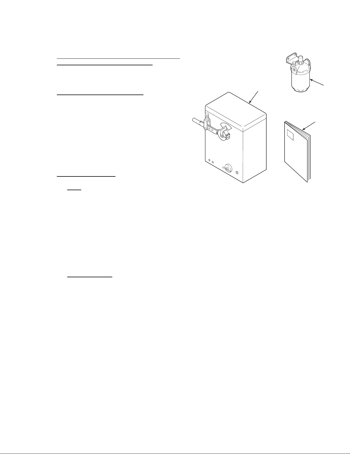
1-1. COMPONENT CHECKLIST OF TYPICAL
SYSTEM (PACKAGE CONTENTS). A typical
PowerVUE 4 x 5 Fan/Damper Actuator package
should contain the items shown in Figure 1-1.
1-2. MODEL NUMBER MATRIX. Use model
number matrix, Table 1-1, to verify your style number. The first part of the matrix defines the model.
The last part defines various options and features of
the actuator. Copy the model number from the data
plate located on the side of the actuator into the top
of matrix Table 1-1. Check the model number against
the actuator features and options, making sure options specified by this number are on the unit. Reference this complete model number for any
correspondence with Rosemount.
1-3. SYSTEM OVERVIEW.
a. Scope. This instruction bulletin supplies details
needed to install, operate, and service the PowerVUE 4 x 5 Torque Type Fan/Damper Actuator
(Figure 1-1). The standard actuator is equipped
with FIELDVUE DVC5000/6000 Series electronics, manual lever, characterization, bypass
valve, supply air filter, clevis, and dust cover.
Actuator options include digital electric position
transmitter with 2 limit contacts (for HART versions only), limit switches, heater/thermostat,
minimum limit stop, manual lock, and air lock
upon loss of plant air.
1. PowerVUE Model PVD 405
Actuator
2. Air Filter
3. Instruction Bulletin
1
Figure 1-1. Typical System Package
2. A bypass valve provides a passage between
the top and bottom of the piston. This
equalizes air pressure on both sides of the
piston, allowing manual positioning of the
device being controlled.
3. The manual lever provides leverage so the
operator can change position of the actuator
by hand.
2
3
RO
SE
M
O
U
NT
29140001
b. Actuator Features. The standard model actua-
tor includes the following features:
1. The DVC5000/6000 electronic controller is
a two-wire instrument and is certified intrinsically safe. The DVC5000 series controller is available with FOUNDATION
fieldbus communications. The DVC6000
4. The supply air filter will remove dispersed
water or oil droplets from the supply air.
5. The clevis provides a connection from actuator to linkage, transferring output arm
movement to the device being controlled.
Three clevis mounting holes are provided at
different points along the output arm.
series controller is available with HART
communications.
6. A dust cover provides a NEMA Type 3 enclosure. It is removable and splash proof.
IB-102-204P
1-1
Page 26
7. The optional manual lock allows the operator to lock the piston and output shaft assembly in any position. This is done by
turning the lock handle fully clockwise,
manually shutting off the air supply, and
opening the bypass valve.
8. The optional mechanical air lock engages
spring-loaded brakes if the loss of plant air
to the actuator occurs.
9. The optional limit stop feature mechani-
cally restricts the stroke of the power piston
and the arc of travel of the output arm.
10. The optional heater/thermostat helps prevent the moisture in the actuator air lines
from freezing. With the heater/thermostat
installed, the actuator can effectively operate in temperatures down to -10°F (-23°C).
c. General Purpose. The PowerVUE 4 x 5 Torque
Type Actuator is used to accurately position the
user’s final control element (flow control
damper, fan inlet vanes, ball valve, etc.).
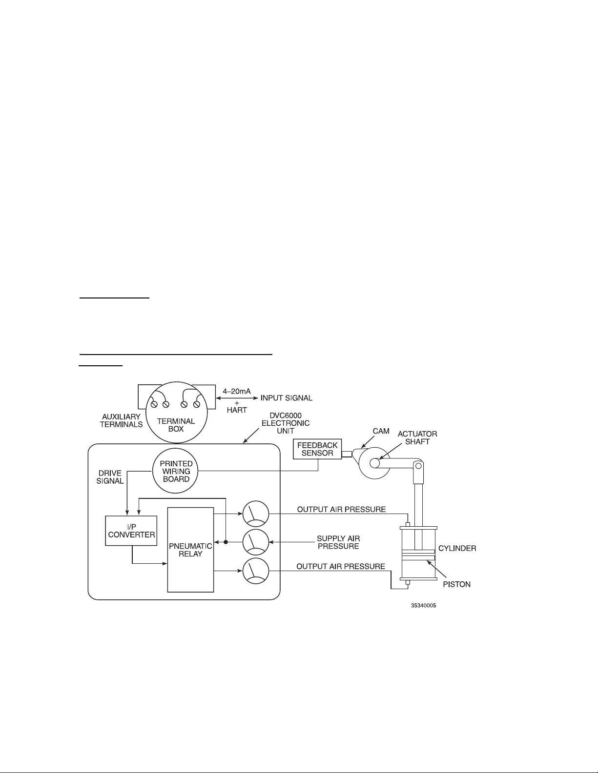
d. Actuator Operation (HART Versions using
DVC6020). Refer to the actuator operation dia-
gram in Figure 1-2. In a typical control system
operation, the user’s process controller sends a 420 mA input signal directly to the DVC6000
electronic unit inside the actuator. The DVC6000
then positions the actuator according to the desired position indicated by the input signal by
converting the input current signal to a pneumatic output pressure. The DVC6000 control
sends the output air pressure to the top and bottom of the pneumatic cylinder locking the piston
in place. As the actuator shaft rotates to its new
position, a cam rotates against a feedback sensor
on the DVC6000 electronic unit. The operating
arm of the actuator is directly connected to the
device control linkage through a clevis.
1. Characterizable Outputs. Customized user
configurable response modes may be incorporated into the DVC6000 electronic unit.
Refer to the FIELDVUE
DVC6000 Series
Digital Valve Controller Instruction Manual.
2. Direction of Rotation. The user can configure for direct or inverse acting rotation by
switching air tubing on the top and bottom
of the pneumatic cylinder.
Figure 1-2. Actuator Operating Diagram – HART Versions using DVC6020
IB-102-204P
1-2
Page 27

3. Digital Communications. The DVC6000
1
controller uses 4-20 mA HART communication protocols. All operator information
for setup and diagnostics is transmitted
digitally via HART communications. A
Rosemount 275 Handheld or similar communicator may be used or a laptop computer with ValveLink Software.
Rosemount’s Asset Management Solutions
(AMS) offers the ValveLink software as an
optional “snap-on” application. Instruments
may be accessed individually or multiplexed through an “Interchange” unit, providing continuous access to any number of
Rosemount instruments.
4. The actuator’s DVC6000 electronic unit,
pneumatic, and mechanical drive devices
are safely housed inside a NEMA Type 3
enclosure (dust cover).
e. Actuator Operation (F
OUNDATION
Fieldbus
Versions using DVC5020f). Refer to the ac-
tuator operation diagram in Figure 1-3. In a typical control system operation, the user’s process
controller sends a fieldbus input signal directly to
the DVC5000 electronic unit inside the actuator.
The DVC5000 then positions the actuator according to the desired position indicated by the
input signal by converting the input current signal to a pneumatic output pressure. The
DVC5000 control sends the output air pressure
to the top of the pneumatic cylinder and the
Fairchild reverse relay. The reverse relay then
sends the appropriate inverse air pressure to the
bottom of the pneumatic cylinder locking the
piston in place. As the actuator shaft rotates to its
new position, a cam mounted on the actuator
shaft rotates against a feedback sensor on the
DVC5000 electronic unit. The actuator shaft is
connected to the operating arm on the outside of
the actuator, which is connected to device control
linkage through a clevis.
1. Characterizable Outputs. Customized user
configurable response modes may be incorporated into the DVC5000 electronic unit.
Refer to the FIELDVUE
DVC5000 Series
Digital Valve Controller Instruction Manual.
2. Direction of Rotation. The user can configure for direct or inverse acting rotation by
switching air tubing on the top and bottom
of the pneumatic cylinder.
3. Digital Communications. The DVC5000
controller uses F
OUNDATION
fieldbus
communication protocols. All operator interface is via the host computer console. A
handheld device will be available in the
future.
4. The actuator’s DVC5000 electronic unit,
pneumatic, and mechanical drive devices
are safely housed inside a NEMA Type 3
enclosure (dust cover).
Figure 1-3. Actuator Operation Diagram - F
OUNDATION
IB-102-204P
1-3
Fieldbus Versions using DVC5020f
Page 28
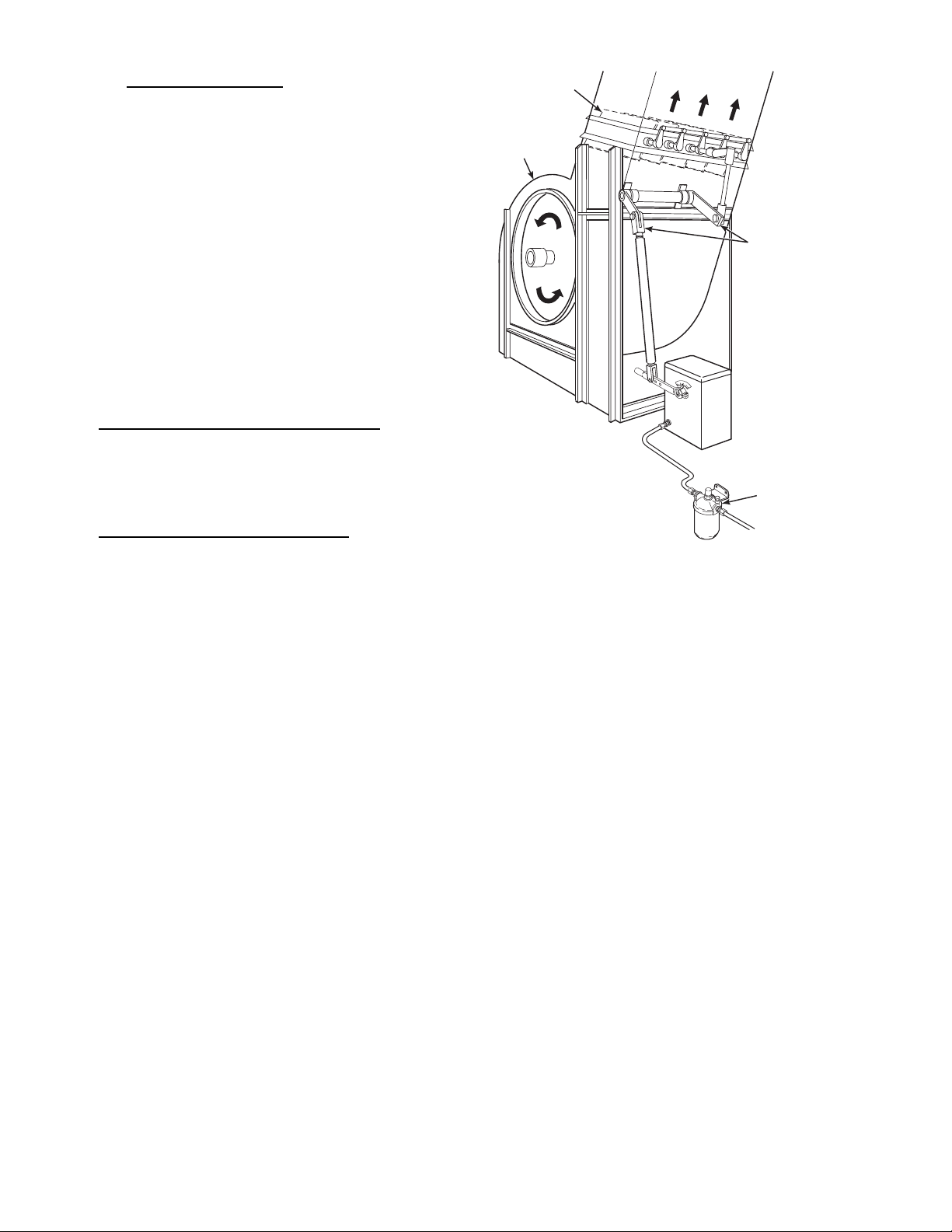
f. System Considerations. Prior to installation of
the PowerVUE 4 x 5 Actuator, check that you
have all components necessary to install the system completely.
Once you have verified that you have all components, select the mounting location. A typical installation is illustrated in Figure 1-4. Determine
where the actuator will be placed in terms of
serviceability, ambient temperatures, environmental considerations, and convenience.
Actuator operating specifications are listed in
Table 1-2. For DVC5000/6000 digital valve
controller specifications refer to the applicable
Digital Valve Controller Instruction Manual. Refer to Section II, Installation, before installing the
digital valve controller.
1-4. MODEL PVD 405 SPECIFICATIONS. Table
1-2 contains information about the Model PVD 405
actuator operating characteristics. Use the table to
make sure that conditions are suitable for the actuator
before choosing the mounting location.
DAMPERS
BLOWER
AIR FLOW
LINKAGE
Powe rVUE
ACTUATOR
AIR
FILTER
1-5. CONTROLLER SPECIFICATIONS. Refer to the
applicable DVC5000 or DVC600 Series Digital
Valve Controller Instruction Manual for controller
specifications.
USER'S
AIR SUPPLY
29140003
Figure 1-4. Typical Actuator Installation
IB-102-204P
1-4
Page 29

Table 1-2. Specifications for Model PVD 405 Actuator
1
Signal Requirements
Control Signal Inputs.................................................................................. 4-20 mA signal with HART or fieldbus
Performance
Positioning Repeatability............................................................................ +0.5% of full stroke or better
Full Stroke Time (unloaded) ...................................................................... 3 sec
Stall Torque ................................................................................................ 400 ft-lbs (542 N·m)
Maximum Friction Load............................................................................. 50% of control torque
Maximum Weight Load ............................................................................. 140 ft-lbs (190 N·m)
Maximum Allowable Cylinder Air Pressure .............................................. 100 psig (690 kPa gage)
Power Air Consumption............................................................................. 10 scfm steady rate
Stroke Length ............................................................................................. 5 in. (127 mm), 80° rotation
Physical Characteristics
Weight ........................................................................................................ 80 lbs (36 kg) typical
Supply Air Inlet.......................................................................................... 1/4 in. NPT female connections
Environmental Requirements
Ambient Temperature Limits
Without Heater .................................................................................... 40° to 122°F (5° to 50°C)
140°F (60°C) with increased maintenance
With Heater ......................................................................................... -10° to 122°F (-23° to 50°C)
140°F (60°C) with increased maintenance
Relative Humidity ...................................................................................... Operable up to 100%
Electronics
See DVC5000/6000 specifications in applicable Digital Valve Controller Instruction Manual
Air Supply Requirements
Operating Air Supply Pressure Range........................................................ 45 to 100 psig (310 to 690 kPa gage)
Recommended Air Supply Pressure........................................................... 100 psig (690 kPa gage)
Fisher-Rosemount has satisfied all obligations coming from the European legislation to harmonize the product requirements in Europe.
The PowerVUE actuator is a subcomponent of an actuating system, including user-provided items such as linkages, bearings, and
dampers. The user must ensure that the entire actuating system is in conformity with the provisions of the European Machinery Directive
EC Machinery Directive 89/392/EEC, as amended by directive 91/368/EEC and Directive 93/44/EEC.
IB-102-204P
1-5
Page 30
1-6. STORAGE INSTRUCTIONS. Use the following
guidelines for actuator unit storage.
a. Storage Environment. Store the actuator in a
warehouse environment that maintains the following conditions:
1. Ambient temperatures are above 45°F
(7°C).
2. Relative humidity is below 80%.
b. Preparation for Storage.
Keep Tectyl 506 away from heat, sparks,
and open flames. Use with adequate ventilation to cure and to prevent an explosive atmosphere from forming.
Coat all non-painted surfaces and exposed metal
with a rust-preventive compound (Tectyl 506 or
a comparable substitute). If not using Tectyl 506,
compare substitute with specifications for Tectyl 506 listed in Table 1-3.
c. Storage Preventive Maintenance. If storing
the actuator unit for more than six months, use
the following preventive maintenance guidelines.
1. Cycle the cylinder and piston, either manually or by air, every 6 months.
2. If there is high humidity, place a bag of
desiccant into the DVC5000/6000 electronic unit.
3. After removing the actuator from storage,
clean and lubricate the unit before installation as follows:
(a) Perform general cleaning and lubrica-
tion per paragraph 6-3.
Use only approved thinning methods
when applying rust-preventive compounds. Do not apply heat to compound.
Fire or explosion may result. Refer to
(b) Clean and lubricate the cylinder and
piston per paragraph 6-4 before installing the actuator.
manufacturer of rust-preventive compound for specific application, thinning,
cleanup, and removal instructions.
Table 1-3. Specifications for Tectyl 506 Rust Preventive Compound
Approximate air dry time................................................................................................ 1 hour
Low temperature flexibility (90° bend with no flaking or cracking) .............................. -10°F (-23°C)
Volatile Organic Content (VOC) .................................................................................... 3.24 lbs/U.S. Gallon (400 grams/liter)
Accelerated Corrosion Tests: [(5% Salt Spray (Hours)]
ASTM (See Note 1)
B-117 at 1.3 mils
(2 x 4 x 1/8 in. polished steel panels) ............................................................... 2000
DIN (See Note 2)
50021 at 32.5 microns
(125 x 200 mm DIN 1623 panels).................................................................... 168
NOTES: (1) ASTM (American Society for Testing and Materials)
(2) DIN (Deutsche Industrie Normen)
IB-102-204P
1-6
Page 31
2
2
SECTION II. INSTALLATION
2-1. OVERVIEW. The actuator is designed to be in-
stalled upright. The floor stand is bolted to a prepared
horizontal foundation. A minimum of 45 psig
(310 kPa gage) to a maximum of 100 psig (690 kPa
gage) supply air pressure is needed at the mounting
location.
2-2. SPECIAL INSTALLATION
CONSIDERATIONS.
a. Foundation. The actuator’s torque is transmit-
ted to the operating arm of the device being positioned. This torque is also transferred to the
actuator’s mass and foundation. To keep the actuator stationary, the foundation must be designed to handle the torque produced. Refer to
paragraph 2-3 for detailed foundation requirements.
b. Supply Air. A supply air pressure of 45 to 100
psig (310 to 690 kPa gage), minimum of 1 scfm
(0.028 m
3
/min), is required. An air filter is provided to remove dispersed water or oil droplets
from supply air.
c. Linkage Design. Final control components
play a large part in a control system. Special
characteristics of the device being controlled affect system response and must be regarded in design and setup of an actuator system.
NOTE
The PowerVUE actuator may be set up to
use only a portion of its total stroke. Refer
to the FIELDVUE
DVC5000/6000 Series
Digital Valve Controllers Instruction Manual for customization information.
ARM
DRIVEN
90°
90°
DRIVE
80°
LINKAGE
80°
In a normal installation, most users install the
linkage with both the drive arm and damper
ARM
driven arm positioned so that both arms establish
an approximate right angle (90°) to the drive line
29330018
at mid range of travel as illustrated in Figure 2-1.
Refer to paragraph 2-5 for detailed information.
Figure 2-1. Angular Relationship of Drive
and Driven Arms
IB-102-204P
2-1
Page 32

2-3. ACTUATOR MOUNTING INSTRUCTIONS.
b. Location Selection.
a. Working Clearance Requirements. Make sure
area is clear of obstructions that will interfere
with actuator operation and maintenance. For a
standard unit, allow an open area of 26.25 in.
(666.75 mm) vertically from foundation, by
16 in. (406.4 mm) side to side, by 28 in.
(711.2 mm) front to back (Figure 2-2). This will
allow for removal of the dust cover, maintenance, and full travel of the operating lever.
28.0
(711.2)
7.5
(190.5)
NOTE: ALL DIMENSIONS ARE IN INCHES
WITH MILLIMETERS IN PARENTHESES.
1.0 (25.4)
7.0
(177.8)
(76.2)
3.0
1. Select the location for the actuator as near
to the device being controlled as possible.
Ensure the necessary clearance for operation and maintenance, as specified in paragraph 2-3.a, is available.
2. Refer to Table 1-2 to ensure environmental
conditions are suitable for the actuator and
DVC5000/6000 electronic unit inside the
actuator.
c. Mounting Procedure.
1. Design and Manufacture of Foundation.
(a) Foundation must be able to withstand
at least 500 ft-lbs (678 N·m) torque
plus 80 lbs (36 kg) weight. Refer to
Figure 2-3 for footprint dimensions of
actuator. Use this footprint as a guide
to design the foundation to match the
base of the actuator.
(b) Mounting holes in the base are drilled
for 1/2 in. foundation bolts. Decide
which foundation material is best
suited for your application, steel or
concrete, then design and manufacture
required foundation.
2. Installation.
(a) Install actuator on foundation with
1/2 in. bolts and standard flat washers.
26.25
(666.75)
16.0
(406.4)
Figure 2-2. Clearance Requirements
29140005
OF CASE
C
L
(160.2)
NOTE:
IB-102-204P
2-2
9.50
1.94
(49.3)
FRONT
3.50
(88.9)
3.50
6.30
(88.9)
ALL DIMENSIONS ARE IN INCHES
WITH MILLIMETERS IN PARENTHESES.
(241.3)
(177.8)
0.56 (14.2) DIAMETER
MOUNTING HOLES (4)
29140006
Figure 2-3. Actuator Unit Mounting and Installation
(Footprint) Drawing
7.0
Page 33

(b) Make sure actuator is level. Check by
2
measuring side to side and front to
back with a level.
(c) If actuator is not level, remove 1/2 in.
mounting bolts and install shims between the actuator and foundation.
Continue this process until the actuator is level when 1/2 in. mounting
bolts are tightened. This will prevent
distortion of the actuator stand.
(d) If installed on a concrete foundation,
grout foundation with additional concrete to prevent distortion of the actuator stand.
2-4. AIR SUPPLY INSTALLATION. Refer to Figure
2-4 and match the torque load required to position
your device to the “maximum torque required” axis
along the bottom of the graph. From this point, move
vertically up to the control torque curve. From the
point that intersects the control torque curve, move
horizontally to the left scale labeled “supply air pressure”. This is the minimum supply air required to develop the required control torque. The stall torque
curve represents the maximum amount of torque the
actuator will produce for a given supply air pressure
before stalling out.
a. Supply Air Requirements. Operating supply
air pressure range for the PowerVUE actuator is
45 psig (310 kPa gage) to 100 psig (690 kPa
gage).
b. Supply Air Connection. Basic schematic is
shown in Figure 2-5.
Figure 2-4. 4 x 5 Actuator Torque Chart
1. Mount bracket for air filter directly on the
back of the stand assembly. If this position
is unsuitable, mount air filter within 15 ft.
(4.6 m) of the actuator.
NOTE
Prior to connecting the supply air line,
purge air system until all moisture and debris are blown out.
2. Purge air supply system and connect air
supply line to the air filter inlet. Run a second line from the air filter outlet to the actuator air input manifold. All fittings are
1/4 in. NPT.
Figure 2-5. Air Piping Schematic
IB-102-204P
2-3
Page 34

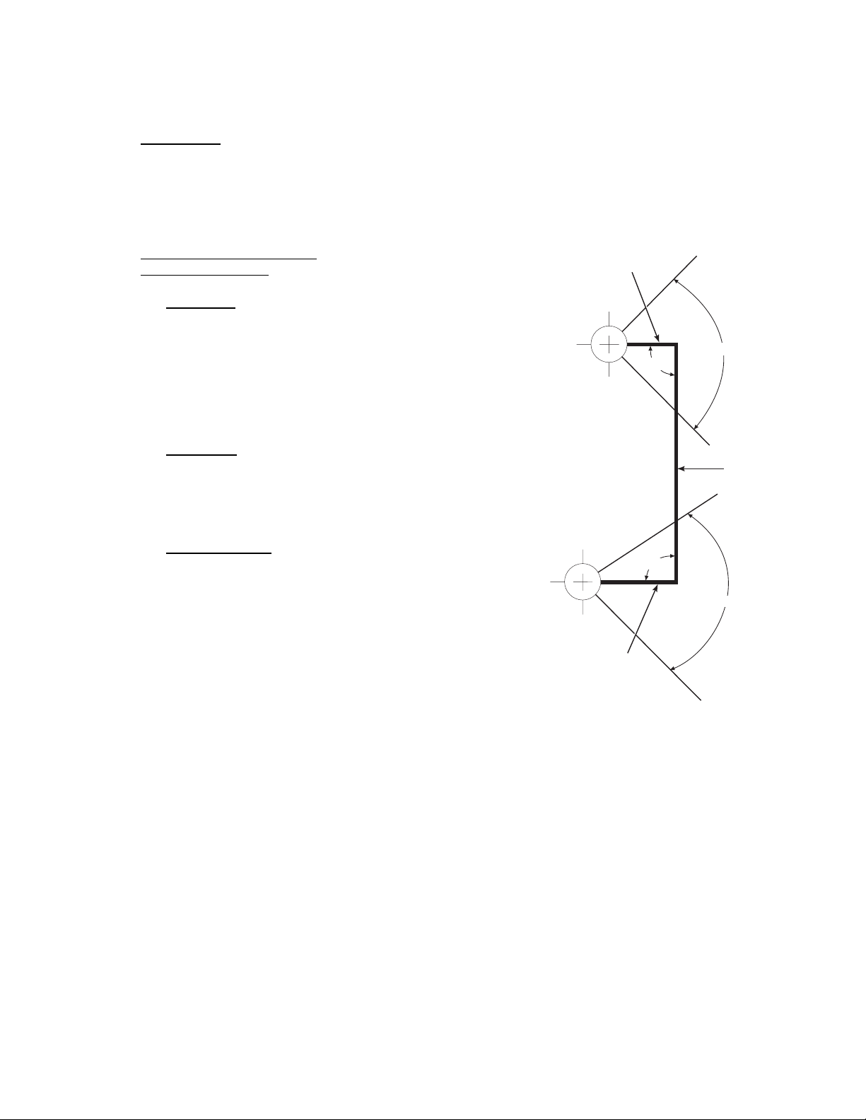
2-5. LINKAGE INSTALLATION. In a normal instal-
lation (paragraph 2-2), both the drive and driven arms
establish an approximate right angle (90°) to the
drive line when at mid-range of travel (Figure 2-1).
Because of this, the “ruler/protractor method” for installing linkage is recommended.
a. With linkage disconnected, move the driven arm
to fully open position so linkage pivot is at A
(Figure 2-6). Mark A1 on a graph or template.
LINKAGE
PIVOT
A
1
o
90
DRIVEN
ARM
1
D
NOTE
The graphed relationship of A
and A2 must
1
match the actual physical relationship of
the two points.
b. Move the driven arm to the closed position so
the linkage pivot is at A
or template. The graphed relationship of A
A
must match the actual physical relationship of
2
. Mark A2 on the graph
2
and
1
the two points.
c. Measure the straight-line distance D between A
and A2.
d. Compare measurement D to the stroke lengths
listed in Figure 2-6. The correct pivot point (B
B
, or B3) is that with the smallest stroke length
2
which still exceeds measurement D. For example, if the vertical distance from A
ures 6 in. (152 mm), select pivot point B
to A2 meas-
1
.
2
e. Position both the drive and driven arms in the
mid-range position. The arms should be parallel
to one another. Connect the linkage to the arms.
A
2
DRIVE
o
O
E
S
P
E
O
L
N
C
DRIVE
ARM
B
1
80
o
90
B
B
3
1
2
CLEVIS
PIVOT POINT SELECTION
,
1
CLEVIS PIN
PIVOT POINT
B
1
B
2
B
3
STROKE LENGTH
IN.
5.0
6.5
8.0
(MM)
127
165
203
29140009
Figure 2-6. Linkage Installation
IB-102-204P
2-4
Page 35

3
3
SECTION III. DVC5000/6000 ELECTRONICS SETUP
3-1. INTRODUCTION. The DVC5000/6000 electronic
unit has been installed, set up, and calibrated at
Rosemount. Additional tuning of the DVC5000/6000
may be required to fit particular applications.
A FIELDVUE DVC5000/6000 Series Digital Valve
Controller Instruction Manual has been provided for
additional information on the DVC5000/6000 electronic unit. Refer to the following sections in the
valve controller instruction manual for specific information.
a. Electrical installation information is contained in
Section 2, Installation.
b. Initial Setup and Calibration, Section 4.
c. Detailed Setup, Section 5.
d. Calibration, Section 6.
e. Maintenance, Section 9.
f. Parts, Section 10.
IB-102-204P
3-1/3-2
Page 36

Page 37

SECTION IV. STARTUP CALIBRATION
4
4-1. REVERSE RELAY CALIBRATION (DVC5000
only). In systems controlled by a DVC5000 series
valve controller, the PowerVUE actuator uses a
Fairchild Model 25463 reverse relay. The reverse relay provides an output pressure which follows the
equation P
sure, K is the spring bias, and P
from the DVC5000 electronic unit. Perform the following procedure to adjust the spring bias of the reverse relay.
= K - PS. Where PO is the output pres-
O
is the input pressure
S
4
CAP NUT
RANGE SCREW
a. Manually position the actuator cylinder off its
end stops.
b. Adjust the supply air to the desired operating air
pressure. It is recommended that the air supply
be adjusted to the level likely to be experienced
during normal operation.
c. Remove the cap nut from the top of the reverse
relay, Figure 4-1.
d. Loosen the lock nut on the range screw.
e. Turn the range screw until the output gage on the
DVC5000 reads 50% of the desired operating air
pressure.
4-2. DVC5000/6000 CALIBRATION. Refer to the
FIELDVUE DVC5000 or DVC6000 Series Digital
Valve Controllers Instruction Manual for information
on calibrating the DVC5000 or DVC6000 valve controller. Calibration information is contained in Section 6.
LOCK NUT
FAIRCHILD
MODEL 25463
REVERSE
RELAY
Figure 4-1. Reverse Relay Calibration
29330019
IB-102-204P
4-1/4-2
Page 38

Page 39

5
5
SECTION V. TROUBLESHOOTING
5-1. OVERVIEW. Refer to the applicable FIELDVUE
DVC5000 or DVC6000 Series Digital Valve Controller Instruction Manual for troubleshooting the
actuator electronics. Figure 5-1 shows an air piping
diagram for actuators controlled with the DVC6000
Figure 5-1. Actuator Air Piping Diagram – HART Versions using DVC6020
series valve controller. Figure 5-2 is the air piping
diagram for actuators controlled with a DVC5000 series controller. Refer to the applicable diagram as an
aid in troubleshooting pneumatic problems.
Figure 5-2. Actuator Air Piping Diagram – F
OUNDATION
IB-102-204P
5-1
Fieldbus Versions using DVC5020f
Page 40

6
LUBRICATION CHART
GREASE GUN FILLED
WITH MCLUBE MoS -793
2
MCLUBE MoS -793
SEE NOTE 2
PISTON ROD
CLEVIS PIN
PISTON
ROD
2
TRUNNION
SCREWS
NOTE 1:
USING A GREASE GUN,
LUBRICATE ZERK FITTINGS
AT PISTON ROD, CLEVIS PIN,
AND AT TRUNNION SCREWS.
Figure 6-1. Lubrication Chart
IB-102-204P
6-0
NOTE 2: WIPE PISTON ROD WITH CLEAN
SHOP TOWEL. APPLY LIGHT
COATING OF MCLUBE MoS -793.
2
WIPE EXCESS GREASE OFF WITH
CLEAN SHOP TOWEL.
NOTE 3: DVC5000 ELECTRONIC UNIT,
REVERSE RELAY, AND MOUNTING
BRACKET NOT SHOWN.
29140010
Page 41
SECTION VI. PERIODIC MAINTENANCE
6
6-1. OVERVIEW. This section describes preventive
maintenance for the PowerVUE Model PVD 405
Fan/Damper Actuator. Preventive maintenance is
necessary at specific intervals to reduce wear and tear
on the actuator.
Before performing any maintenance or
repair action on actuator, shut off supply air and any electronic signals to actuator. Isolate actuator from all systems
connected to the actuator. Severe injury
or death may result from large torque
produced by actuator.
6-2. MAINTENANCE SCHEDULE. Use Table 6-1 as
a guideline for preventative maintenance. The frequency of maintenance varies directly with plant
conditions and operational load. Extremely dusty
conditions or high temperatures will require more
frequent maintenance to the actuator.
Clean actuator in a well ventilated area.
Avoid inhalation of solvent fumes and
prolonged exposure of skin to cleaning
solvent. Follow all instructions on the
Material Safety Data Sheet (MSDS) of
the solvent being used. Severe injury or
death may result from improper use.
6-3. GENERAL CLEANING AND LUBRICATION.
Clean actuator’s exterior of all grease buildup with
commercial dry cleaning solvent. To lubricate actuator, use McLube MoS
-793 or equivalent and refer
2
to Figure 6-1.
McLube MoS
-793 can be purchased from
2
Rosemount Analytical Inc., P/N 183512, or directly
from the manufacturer:
McGee Industries, Inc.
9 Crozerville Rd.
Aston, PA 19014
6-4. CYLINDER AND PISTON CLEANING AND
LUBRICATION. Disassemble, clean, and lubricate
piston and cylinder assembly approximately every
two years, Table 6-1. Refer to Figure 6-2 for the following procedure.
Before performing any maintenance or
repair action on actuator, shut off supply air and any electronic signals to actuator. Isolate actuator from all systems
connected to the actuator. Severe injury
or death my result from large torque
produced by actuator.
a. Remove actuator from service.
b. Shut off supply air valve. Open bypass valve.
Table 6-1. Maintenance Schedule
TIME INTERVAL
(Approximate) MAINTENANCE ACTION
6 months
Perform general cleaning and lubrication. Refer to paragraph 6-3.
2 years
Lubricate and clean cylinder and
piston assemblies. Refer to paragraph 6-4.
IB-102-204P
6-1
Residual air must be bled off of cylinder
before removal of cylinder head. If air is
not bled off, eye injury may result.
c. Bleed residual air through DVC5000/6000 and
reverse relay air connections.
Page 42
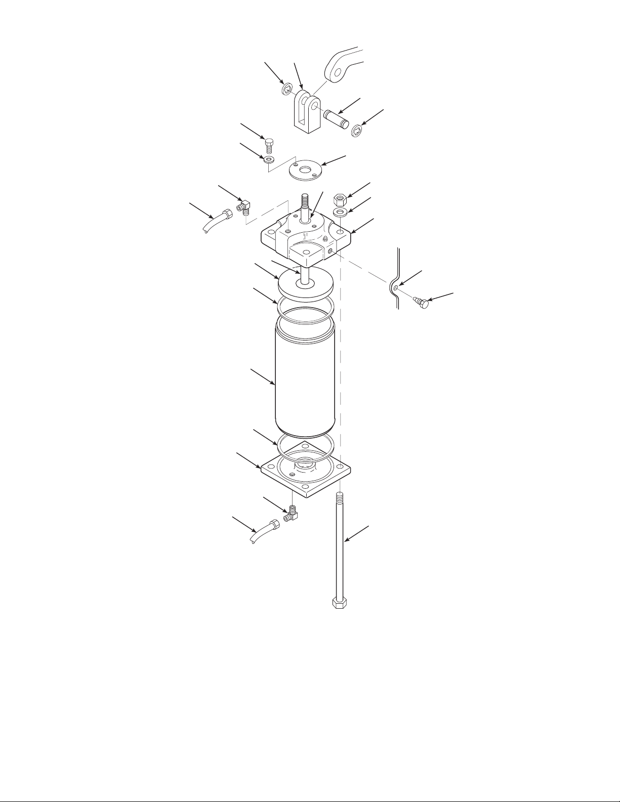
1. Upper Air Hose
2. 90° Elbow
3. Upper Cylinder Head
4. Lower Air Hose
5. Lower Cylinder Head
6. Retaining Ring
7. Clevis Pin
8. Clevis Head
9. Cylinder
10. Trunnion Screw
11. Piston
12. Tie Bolt
13. Hex Nut
14. Washer
15. Head Gasket
16. Piston Rod
17. Hex Head Cap Screw
18. Washer
19. Packing Cover
20. Female Adapter
19
SHAFT
LEVER
7
13
14
3
6
STAND
ASSEMBLY
TRUNNION
HOLE
10
6
17
18
2
1
16
11
15
8
20
NOTE: NOT ALL ITEMS IDENTIFIED ARE
AVAILABLE FOR SALE FROM ROSEMOUNT.
SEE SECTION IX, RECOMMENDED SPARE
PARTS, FOR A LIST OF AVAILABLE
RECOMMENDED PARTS.
Figure 6-2. Cylinder Exploded View (Cleaning and Lubrication)
9
15
5
2
4
12
29140011
IB-102-204P
6-2
Page 43
d. Remove upper air hose (1,Figure 6-2) from 90°
6
elbow (2) at upper cylinder head (3). Mark air
hose “upper.”
m. With a clean shop towel and commercial grade
dry cleaning solvent, wipe interior surface of
cylinder (9). Allow to air dry before assembly.
e. Remove lower air hose (4) from 90° elbow (2) at
lower cylinder head (5). Mark air hose “lower.”
f. Remove retaining rings (6) and drive out clevis
pin (7) from clevis head (8).
g. While supporting cylinder (9), remove trunnion
screws (10).
h. Remove assembled cylinder from trunnion and
move it to a workbench to continue disassembly.
Do not scratch piston rod. Use caution
when removing and handling upper
cylinder head, piston, and piston rod. If
piston rod is scratched, actuator will
produce lower torque and cause decreased packing life.
i. Remove hex nuts (13), washers (14), and tie
bolts (12).
Do not pull piston and shaft assembly
out of cylinder head. Damage to packing
gland bushings and V-packing may
occur.
j. Remove upper cylinder head (3) from cylinder
by sliding piston (11) out of cylinder (9).
k. Remove and discard upper and lower cylinder
head gaskets (15).
l. Clean old grease off piston (11) and piston rod
(16). Wipe with commercial grade dry cleaning
solvent and let air dry. Pack concave area of
piston with McLube MoS
-793 grease. Wipe off
2
excess grease with clean shop towel.
n. Remove hex head cap screws (17) and washers
(18) securing packing cover (19) to upper cylinder head (3). Remove packing cover from upper
cylinder head.
o. Clean and inspect female adapter (20) under
packing cover (19). Replace female adapter,
packing, and male adapter if female adapter appears damaged or was leaking. Refer to Section
VII for replacement procedures.
p. Pack area around female adapter (20) with
McLube MoS
-793 grease or equivalent. Secure
2
packing cover (19) to upper cylinder head (3)
with hex head cap screws (17).
q. Install tie bolts (12) through lower cylinder head
(5).
r. Install cylinder (9) with a new cylinder head
gasket (15) onto lower cylinder head (5).
s. Place new upper cylinder head gasket (15) on
top of cylinder. Ensuring both gaskets are in
place, slide piston (11) and upper cylinder head
assembly onto cylinder (9). Align tie bolts
through upper cylinder head (3) holes and secure
with washers (14) and hex nuts (13). Tighten hex
nuts evenly using a diagonal tightening
sequence.
t. Install cylinder assembly onto actuator frame by
aligning upper cylinder head (3) mounting holes
with trunnion holes in stand assembly. Secure
cylinder in stand with trunnion screws (10).
u. Secure clevis head (8) to shaft lever with clevis
pin (7). Secure clevis pin with retaining rings (6).
v. Install air hose marked “upper” (1) to 90° elbow
(2) at upper cylinder head (3). Install air hose
marked “lower” (4) to 90° elbow at lower cylinder head (5).
w. Refer to paragraph 4-2 and calibrate
DVC5000/6000 electronic unit. Return actuator
to service.
IB-102-204P
6-3
Page 44

7
SHAFT
3
1
4
5
LEVER
2
1
6
9
10
1. Retaining Ring
2. Clevis Pin
12
3. Clevis Head
4. Hex Head Cap Screw
5. Washer
6. Packing Cover
7. Trunnion Screw
8. Upper Cylinder Head
9. 90° Elbow (Brass or Stainless Steel)
10. Air Supply Hose (Upper)
11. Air Supply Hose (Lower)
12. Grease Fitting
13. Hex Nut
14. Washer
15. Tie Bolt
16. Lower Cylinder Head
17. Cylinder Head Gasket
18. Cylinder
19. Stop Nut
20. O-ring
21. Piston
22. Piston Rod
23. Female Adapter
24. V-Packing
25. Male Adapter
21
25
24
20
19
22
23
16
17
13
14
STAND
ASSEMBLY
8
TRUNNION
9
7
HOLE
17
18
11
NOTE: NOT ALL ITEMS IDENTIFIED ARE
AVAILABLE FOR SALE FROM ROSEMOUNT.
SEE SECTION IX, RECOMMENDED SPARE
PARTS FOR A LIST OF AVAILABLE
RECOMMENDED PARTS.
Figure 7-1. Cylinder Exploded View (Parts Replacement)
IB-102-204P
7-0
15
29140012
Page 45

SECTION VII. CORRECTIVE MAINTENANCE
6
7-1. OVERVIEW. This section describes corrective
maintenance for the PowerVUE Model PVD 405
Fan/Damper Actuator. If the specific cause of a
problem is not known, refer to Section V, Troubleshooting. Spare parts referred to are available from
Rosemount. Refer to Section IX of this manual for
part numbers and ordering information.
Before performing any maintenance or
repair action on actuator, shut off supply air and any electronic signals to actuator. Isolate actuator from all systems
connected to the actuator. Severe injury
or death may result from large torque
produced by actuator.
7-2. PARTS REPLACEMENT.
a. Cylinder. Use the following procedure to disas-
semble and reassemble the power cylinder on
model PVD 405 actuator. Replace items that are
damaged or worn beyond a serviceable condition
as determined by troubleshooting or by inspection. Replace cylinder head gaskets each time
cylinder is disassembled.
2. Shut off supply air valve. Open bypass
valve.
Residual air must be bled off of cylinder
before removal of cylinder head. If air is
not bled off, eye injury may result.
3. Bleed residual air through DVC5000/6000
and reverse relay air connections.
4. Remove upper air hose (10, Figure 7-1)
from 90° elbow (9) at upper cylinder head
(8). Mark air hose “upper.”
5. Remove lower air hose (11) from 90° elbow (9) at lower cylinder head (16). Mark
air hose “lower.”
6. Remove retaining rings (1) and drive out
clevis pin (2) from clevis head (3).
7. While supporting cylinder (18), remove
trunnion screws (7).
8. Remove assembled cylinder from trunnion.
Move it to a workbench to continue
disassembly.
Before performing any maintenance or
repair action on actuator, shut off supply air and any electronic signals to actuator. Isolate actuator from all systems
connected to the actuator. Severe injury
or death may result from large torque
produced by actuator.
1. Remove actuator from service.
IB-102-204P
7-1
Do not scratch piston rod. Use caution
when removing and handling upper
cylinder head, piston, and piston rod. If
piston rod is scratched, actuator will
produce lower torque and cause decreased packing life.
9. Remove hex nuts (13), washers (14), and
tie bolts (15).
Page 46

Do not pull piston and shaft assembly
out of cylinder head. Damage to packing
gland bushings and V-packing may occur.
10. Remove upper cylinder head (8) by sliding
piston (21) out of cylinder (18).
11. Remove and discard upper and lower cylinder head gaskets (17).
12. If piston is to be replaced, remove stop nut
(19), o-ring (20), and piston (21). Replace
with new piston and o-ring; secure with
same stop nut.
18. Pack concave area of piston with McLube
MoS
-793 type grease or equivalent.
2
Lightly coat piston rod (22) with McLube
MoS
-793 grease. Wipe off excess grease
2
with clean shop towel.
19. Install tie bolts (15) through lower cylinder
head (16).
20. Install cylinder (18) with a new cylinder
head gasket (17) onto lower cylinder head
(16).
21. Place new upper cylinder head gasket (17)
on top of cylinder. Making sure both gaskets are in place, slide piston (21) into upper cylinder head (8) and onto cylinder
(18).
13. If piston was not replaced, clean old grease
off piston (21) and piston rod (22). Wipe
with commercial grade dry cleaning solvent
and let air dry.
14. Remove hex head cap screws (4) and washers (5) securing packing cover (6) to upper
cylinder head (8). Remove packing cover
from upper cylinder head.
15. Remove and inspect female adapter (23).
Replace female adapter, V-packing (24),
and male adapter (25) as a set if any one
appears damaged or if air was leaking
through packing.
16. Install male adapter (25), V-packing (24),
and female adapter (23). Pack area around
female adapter with McLube grease or
equivalent. Secure packing cover (6) to upper cylinder head (8) with hex head cap
screws (4) and washers (5).
17. With a clean shop towel and commercial
grade dry cleaning solvent, wipe interior
surface of cylinder (18). Allow to air dry
before assembling.
22. Align tie bolts (15) through upper cylinder
head (8) holes and secure with hex nuts
(13) and washers (14). Tighten hex nuts
evenly, using a diagonal tightening
sequence.
23. Install cylinder assembly by aligning upper
cylinder head (8) mounting holes with trunnion holes in stand assembly. Secure cylinder in stand with trunnion screws (7).
24. Attach clevis head (3) to shaft lever with
clevis pin (2). Secure clevis pin with retaining rings (1).
25. Install air hose marked “upper” (10) to 90°
elbow (9) at upper cylinder head (8). Install
air hose marked “lower” to 90° elbow at
lower cylinder head (16).
26. Open supply air valve and check for leaks
by using a “snoop” type leak detector.
27. Calibrate the electronic unit according to
instrctions in the FIELDVUE DVC5000 or
DVC6000 Series Digital Valve Controllers
Instruction Manual. Return the actuator to
service.
IB-102-204P
7-2
Page 47
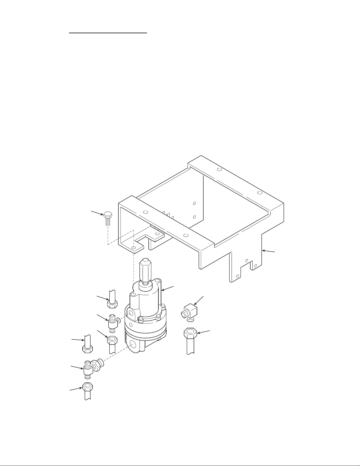
b. Reverse Relay (DVC5000 only). For DVC5000
6
controlled actuators, use the following procedure
to replace a faulty reverse relay.
1. Shut off actuator air supply and electronic
signals. If the unit is equipped with air lock
or manual lock, turn the release handle fully
counterclockwise to engage the brake.
2. Refer to Figure 7-2. Label all air lines for
proper positioning on reassembly.
3. Loosen supply air lines (2) and DVC5000
air lines (3) to bleed residual air.
5. Remove screws (1). Remove reverse relay
(8).
6. Remove fittings (5, 6 and 7). Install fittings
in same locations on replacement reverse
relay.
7. Install replacement reverse relay (8) on
mounting bracket (9) with screws (1).
8. Reinstall supply air lines (2), DVC5000 air
lines (3), and cylinder air line (4) to their
proper fittings.
4. Disconnect supply air lines (2), DVC5000
air lines (3), and cylinder air line (4) at fittings (5, 6 and 7).
1
8
3
9. Calibrate the reverse relay according to
paragraph 4-1.
9
7
6
1. Screw
2. Supply Air Line
3
2
4
3. DVC5000 Air Line
4. Cylinder Air Line
5. T-Fitting
6. T-Fitting
7. Elbow Fitting
5
8. Reverse Relay
9. Mounting Bracket
2
29140018
Figure 7-2. Reverse Relay Replacement
IB-102-204P
7-3
Page 48

c. DVC6000 Electronic Unit. Use the following
procedure for replacement of a faulty DVC6000
electronic unit.
6. Remove four bolts (2) securing DVC6000
electronic unit to mounting bracket (1).
Remove DVC6000 electronic unit.
1. Shut off actuator air supply and electronic
signals. If the unit is equipped with air lock
or manual lock, turn the release handle fully
counterclockwise to engage the brake.
2. Disconnect any electrical leads to the
DVC6000 terminal.
3. Refer to Figure 7-3. Label all air lines for
proper positioning on reassembly.
4. Loosen supply air line (7) and both cylinder
air lines (8) to bleed residual air.
5. Disconnect supply air line (7) and cylinder
air lines (8) at fittings (6).
7. Remove elbow fittings (6). Install fittings in
same locations on replacement DVC6000
electronic unit.
8. Install replacement DVC6000 electronic
unit on mounting bracket (1) with bolts (2).
9. Reinstall supply air line (7) and cylinder air
lines (8) to their proper locations.
10. Refer to the FIELDVUE DVC6000 Series
Digital Valve Controllers Instruction Manual, Sections 4 and 6 to calibrate the
DVC6000 electronic unit.
1
9
DVC6000
ELECTRONIC
UNIT
2
3
4
5
3
4
5
6
7
1. Mounting Bracket
2. Bolt, 1/4-20 x 1/2 in.
3. Lock Washer
4. Flat Washer
5. Bolt,1/4-20 x 3/4 in.
6. Elbow Fitting
6
8
7. Supply Line
8. Cylinder Air Line
9. Brace
Air
35340006
Figure 7-3. DVC6000 Electronic Unit Replacement
IB-102-204P
7-4
Page 49

d. DVC5000 Electronic Unit. Use the following
6
procedure for replacement of a faulty DVC5000
electronic unit.
1. Shut off actuator air supply and electronic
signals. If the unit is equipped with air lock
or manual lock, turn the release handle fully
counterclockwise to engage the brake.
2. Disconnect any electrical leads to the
DVC5000 terminal.
3. Refer to Figure 7-4. Label all air lines for
proper positioning on reassembly.
4. Loosen supply air line (4) and cylinder and
reverse relay air line (5) to bleed residual
air.
6. Remove four bolts (1), washers (2), and
nuts (3) securing DVC5000 electronic unit
to mounting bracket (7). Remove DVC5000
electronic unit.
7. Remove both elbow fittings (6). Install fit-
tings in same locations on replacement
DVC5000 electronic unit.
8. Install replacement DVC5000 electronic
unit on mounting bracket (7) with four bolts
(1), washers (2), and nuts (3).
9. Reinstall supply air line (4) and cylinder
and reverse relay air line (5) to their proper
locations.
5. Disconnect supply air line (4) and cylinder
and reverse relay air line (5) at elbow
fittings (6).
6
5
1
2
DVC5000
ELECTRONIC
UNIT
6
4
10. Refer to the FIELDVUE DVC5000/6000
Series Digital Valve Controllers Instruction
Manual, Sections 4 and 6 to calibrate the
DVC5000 electronic unit.
1. Bolt
2. Washer
3. Nut
4. Supply Air Line
5. Cylinder and Reverse
Relay Air Line
6. Elbow Fitting
7. Mounting Bracket
7
3
29140019
Figure 7-4. DVC5000 Electronic Unit Replacement
IB-102-204P
7-5/7-6
Page 50

Page 51

8
8
SECTION VIII. OPTIONS
8-1. OVERVIEW. The options for the PowerVUE
Model PVD 405 Fan/Damper Actuator covered in
this section include the air lock, heater/thermostat,
and SPA with HART alarm.
8-2. AIR LOCK.
a. Description. The air lock, Figure 8-1, automati-
cally locks the actuator and shaft assembly when
there is a loss of supply air. When supply air
pressure falls below a set value, the air lock diaphragm collapses causing a spring to move the
lock lever. This clamps the friction plate and
locks the piston and shaft assembly. Upon loss of
supply air pressure, the automatic lock can be
overridden by turning the air lock release handle
fully clockwise. The operator must then open the
bypass valve, manually position the output shaft,
and lock the output shaft by turning the air lock
release handle fully counterclockwise.
b. Adjustment.
Before performing any maintenance or
repair action on actuator, shut off supply air and any electronic signals to actuator. Isolate actuator from all systems
connected to the actuator. Severe injury
or death may result from large torque
produced by actuator.
1. Remove actuator from service, close supply
air shutoff valve, and remove any electronic
signals to the actuator.
2. Turn the air lock release handle, Figure 8-1,
clockwise until lock lever (1, Figure 8-2)
brake shoe is clear of the sector.
LOCK
LEVER
BYPASS
VALV E
AIR LOCK
RELEASE
HANDLE
.
29140014
Figure 8-1. Air Lock
IB-102-204P
8-1
Page 52

1
7
8
1. Lock Lever
2. Brake Shoe
3. Spacer Block
4. Anvil Screw
5. Hex Head Screw
(3/8-16 x 1-1/2)
6. Lock Washer
(3/8 Int Tooth)
7. Lock Fulcrum
8. Pivot Pin
Figure 8-2. Air Lock Brake Exploded View
3. Turn the brake anvil screw (4) in until the
anvil brake shoe (2) just clears face of
sector.
4. Turn air lock release handle fully counterclockwise.
5. Restore supply air and electrical signals to
actuator.
c. Air Lock Brake Shoe Replacement.
2
3
2
3
6
5
4
29140015
2. Remove hex head screws (5, Figure 8-2)
and lock washers (6).
3. Set spacer blocks (3) aside and move assembled lock lever (1) back, clear of sector.
4. Using a punch, tap brake shoes (2) free
from lock lever (1).
5. Remove anvil screw (4) and brake shoe (2).
Pull brake shoe out of anvil screw.
Before performing any maintenance or
repair action on actuator, shut off supply air and any electronic signals to actuator. Isolate actuator from all systems
connected to the actuator. Severe injury
or death may result from large torque
produced by actuator.
1. Remove actuator from service, close supply
air shutoff valve, and remove any electronic
signals to the actuator.
6. Install new brake shoe (2) in anvil screw (4)
and replace anvil screw in air lock frame.
7. Install new brake shoe (2) in lock lever (1).
8. Position lock lever against frame with
spacer blocks (3) and secure in place with
lock washers (6) and hex head screws (5).
9. Adjust air lock brake in accordance with
paragraph 8-2.a.
10. Restore supply air and electrical signals to
actuator.
IB-102-204P
8-2
Page 53

d. Diaphragm Replacement.
8
3. Remove socket head cap screws (14, Figure
8-3) and air lock housing (13) from
actuator.
Before performing any maintenance or
repair action on actuator, shut off supply air and any electronic signals to actuator. Isolate actuator from all systems
connected to the actuator. Severe injury
or death may result from large torque
produced by actuator.
1. Remove actuator from service, close supply
air shutoff valve, and remove any electronic
signals to the actuator.
2. Turn air lock release handle, Figure 8-1,
fully counterclockwise to release any pressure on the diaphragm.
4. Hold rod sleeve (8), being careful not to
strip threads, and remove diaphragm stud
(12) and diaphragm (11) from actuator.
5. Make sure that diaphragm washer (9) and
diaphragm seat (10) are in place and install
new diaphragm (11), securing with diaphragm stud (12).
6. Install air lock housing (13), securing with
socket head cap screws (14).
7. Restore supply air and electrical signals to
actuator.
5
4
3
6
7
1
2
9
10
11
12
13
1. Tubing, 1/4 OD
2. Union, Brass
3. Lock Nut
4. Spring
14
5. Air Lock Rod
6. Threaded Stud
8
Union, Stn Stl
1.8 IPS x 1/4 OD
8. Rod Sleeve
9. Diaphragm Washer
10. Diaphragm Seat
11. Diaphragm
12. Diaphragm Stud
13. Air Lock Housing
14. Socket Head Cap Screw
(3/8-16 x 3/4)
7. Tripod Top
29140016
Figure 8-3. Air Lock Diaphragm Exploded View
IB-102-204P
8-3
Page 54

8-3. HEATER/THERMOSTAT. The heater/thermostat
helps prevent the freezing of moisture in actuator air
lines. With the heater/thermostat installed, the actuator can effectively operate in temperatures down to
-10°F (-23°C). Operation below this ambient temperature is not recommended.
a. Heater Replacement.
Before performing any maintenance or
repair action on actuator, shut off supply air and any electronic signals to actuator. Isolate actuator from all systems
connected to the actuator. Severe injury
or death may result from large torque
produced by actuator.
5. Connect black heater lead (1) to terminal 2
and white heater lead (2) to terminal 5 on
terminal block (3).
b. Thermostat Replacement.
Before performing any maintenance or
repair action on actuator, shut off supply air and any electronic signals to actuator. Isolate actuator from all systems
connected to the actuator. Severe injury
or death may result from large torque
produced by actuator.
1. Remove actuator from service, close supply
air shutoff valve, and remove any electronic
signals to the actuator.
1. Remove actuator from service, close supply
air shutoff valve, and remove any electronic
signals to the actuator.
2. Remove heater supply leads (1 and 2,
Figure 8-4) from terminals 2 and 5 on terminal block (3).
3. Remove screws (4), nuts (5), washers (6),
and heater (7) from mounting bracket (8).
4. Install new heater, securing with screws (4),
washers (6), and nuts (5).
2. Remove thermostat leads (9 and 10, Figure
8-4) from terminals 3 and 4 on terminal
block (3).
3. Remove screws (11), washers (12),
grounding lead (13), and thermostat (14)
from mounting bracket (8).
4. Install new thermostat. Reattach ground
lead.
5. Connect thermostat leads (9 and 10) to terminals 3 and 4 on terminal block (3).
IB-102-204P
8-4
Page 55
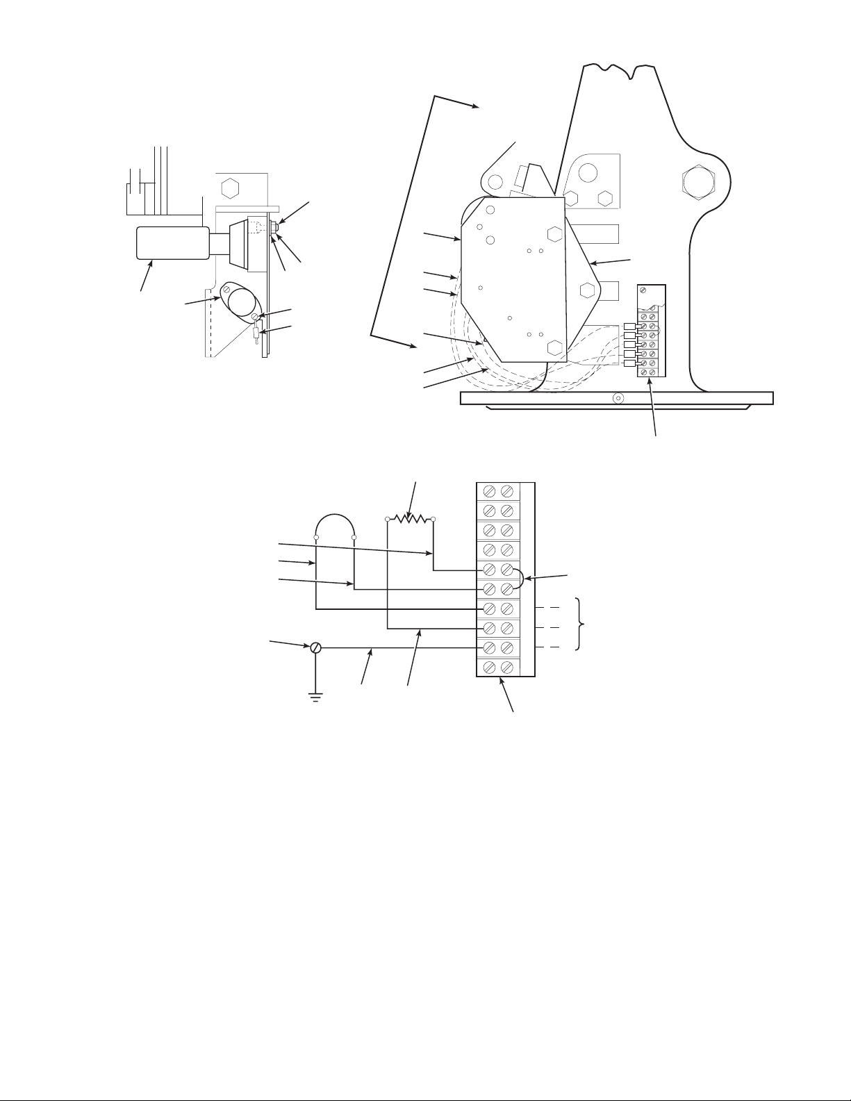
B
8
4
16
7
14
VIEW B-B
MOUNTING SCREW
FOR THERMOSTAT
10
8
6
5
11, 12
13
1
2
13
B
9
10
3
150W
HEATER
1
9
BLK
BLK
BLK
WHT
GRN
123 4 5678
15 JUMPER
L
HEATER POWER SUPPLY
120V, 60Hz, 150W
N
T.B. SCREW SIZE #5
G
13
WIRING DIAGRAM FOR HEATER/THERMOSTAT
1. Heater Lead (Black)
2. Heater Lead (White)
3. Terminal Block
4. Screw
5. Nut
6. Washer
7. Heater
8. Mounting Bracket
2
3
29140013
9. Thermostat Lead
10. Thermostat Lead
11. Screw
12. Washer
13. Grounding Lead
14. Thermostat
15. Jumper
16. Heater Bracket
Figure 8-4. Heater/Thermostat
IB-102-204P
8-5
Page 56

8-4. HART Site Programmable Alarm (DVC6000
Series Controller only).
a. Overview. The DVC6000 series valve control-
ler includes a cam-driven position potentiometer
to provide feedback information about actuator
position. The position transmitter is the source of
all discrete and absolute position information for
the valve controller. The feedback information is
transmitted via HART communications from the
control room to the DVC6000 controller.
Some users, however, want an independent position feedback to confirm the actuator position.
The Moore Industries HART Site Programmable
Alarm (SPA) option provides this independent
position feedback.
b. Capabilities. The HART Site Programmable
Alarm is provided for customers that want independent confirmation of actuator position. The
SPA communicates via HART and can initiate
the following actions based on the digital position signal:
1. Dip Switch Settings.
Password – no recommendation
(user decide)
Failsafe/Non-Failsafe – non-failsafe
Current Source, Sink, or Voltage – set to
Current Source
2. Relay Setup.
Relay #1 – HART alarm:
Set to Primary vs Secondary
Set to Normal, vs. Burst
Set “Number of variables” to 1
(factory default)
Set “Number of Trys” to 1
(factory default)
Set “HART Source” settings to:
Bit 7 on
Bit 5 off
Bit 4 off
Bit 3 on
Bit 2 on
Bit 1 off
Bit 0 on
1. Retransmit a single 4-20 mA position signal. Many users want this capability to represent or record the PowerVUE position.
2. Initiate 2 or 3 contact closures based upon
actuator position.
3. Initiate a contact closure upon the loss of
HART communications or upon a predetermined set of SPA fault conditions.
c. Installation. The SPA is a ¼ DIN electronic
module that can be mounted near the control
room in the cabinetry where I/O terminations are
located. The SPA should be wired in parallel to
the 4-20 mA control signal routed from the control room to the DVC6000.
d. Setup. Install and set up the DVC6000 com-
pletely before setting up the SPA unit. Instructions for setting up the SPA are included in the
Moore Instruction Manual, 224-741-00B.
Recommended values for this sample setup are
as follows:
Alarm Source Information, Relays 2,3,4:
Set “Analog Output Source” to
PV (process variable)
Set “Relay Sources” to PV
Configuring Miscellaneous Options:
Set linearization off “LINR OFF”
Set Scaling to “AUTO”
Set Engineering Units to “PCT”
Set Source for SPA display to PV
Set function of Relay #2 to
“TRIP” vs. “FAULT”
Set Upscale/Downscale Drive to
“LOW”
Setting Engineering Units:
Set “PCT” for all
Smart Scaling do not use
Scaling the HART input – complete
this procedure
Customizing Input Linearization –
do not use
Smart Scaling of SPA Analog
Output – complete this procedure
Trimming the SPA Analog Output –
complete this procedure
IB-102-204P
8-6
Page 57

Configuring the SPA Relays per the
8
“Flame Safety Interface” example:
Alarm #2:
Enter Trip – Set to 95%
(input trip is inactive)
Deadband – Set to “0”
Delay – Set to “0 sec”
Hi/Lo Alarm Function –
Set for “Hi”
Latching – Set to “OFF”
Alarm #3:
Input Trip – Set 22%
(2nd input trip inactive)
Deadband – Set to “0”
Delay – Set to “0 sec”
Hi/Lo Alarm Function –
Set to “Lo”
Latching – Set to “OFF”
Alarm #4:
Input Trip – Set to 18%
(2nd input trip is inactive)
Deadband – Set to “0”
Delay – Set to “0 sec”
Hi/Lo Alarm Function –
Set to “Hi”
Latching – Set to “OFF”
e. Limit Switch Function. Traditionally, limit
switches were tripped upon contact with a cam
on the rotary output shaft of the actuator. The
lobe of the cam caused switch actuation for 10 to
20% of the rotary travel of the actuator shaft.
The SPA unit receives actuator position data via
HART communications and controls two relays
based on the digital position signal. (The SPA
unit initiates contact closure when the PowerVUE travel is above or below a given position
only. Two contact closures are used to confirm a
given position or range.)
The following “flame safety interface” example
illustrates how to set up the unit for an operation
wherein the relay contact closures control an
automated boiler light-off system. Refer to the
timing chart and wiring schematic shown in Figures 8-5 and 8-6.
1. User wishes to confirm that actuator is
above 95% (purge). Contact #2 is normally
open and closes at or above 95%.
2. User wishes to confirm that actuator is at
22% of travel (light-off). Contact #3 is
normally open and closes below 22%.
Contact #4 is normally open and closes
above 18%. The two contacts must both be
closed in order for the resultant contact to
close, confirming actuator position between
18 and 22% (light-off).
Using contacts #1 and #2, any failure within the
SPA unit will cause outputs to go to a default
value. In this example, all contacts fail to the
open position. The contacts are also wired such
that a fault can be indicated to the user.
PURGE
95%
BOILER
POSITION
22%
ACTUATOR
18%
RELAY #2 (NO) CLOSED (OPENS BELOW 95%)
RELAY #3 (NO) CLOSED (#3 CLOSED BELOW 22%, OPEN ABOVE 22%)
RELAY #4 (NO) CLOSED (#4 CLOSED ABOVE 18%, OPEN BELOW 18%)
LIGHT OFF
TIME
35340007
Figure 8-5. Timing Chart for Flame Safety Application
IB-102-204P
8-7
Page 58
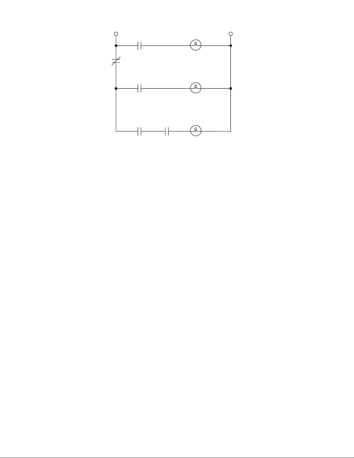
RELAY 1
LINE 1
N.C.
RELAY 1
N.O.
HART
FAU LT
NEUTRAL
RELAY 2
N.O.
RELAY 3
N.O. N.O.
RELAY 4
PURGE
BOILER
LIGHT OFF
35340008
Figure 8-6. Wiring Schematic for Flame Safety Application
IB-102-204P
8-8
Page 59

9 9
9
SECTION IX. RECOMMENDED SPARE PARTS
NOTE
Refer to FIELDVIEW DVC5000/6000 Series Digital Valve Controllers Instruction Manual, Section 10
for parts information for the DVC5000/6000 electronic unit.
Table 9-1. Recommended Spare Parts for PowerVUE Model PVD 405 Fan/Damper Actuator
FIGURE and
INDEX NUMBER PART NUMBER DESCRIPTION QTY
Not Shown 1A97805G02 Spare Parts Kit 4 x 5 Actuator 1
O-ring (120039-007) 1
O-ring (120039-010) 1
Cylinder Head Gasket (141843) 2
V-Packing Rings (141885-001) 3
Shoe Plug (141889) 2
Piston (142031) 1
Gasket (5057-002) 1
Plastic Tube Air Line (6292A08H04) 2
Ferrules for Cylinder Tubing (6292A78G03) 4
1A9780-5G03 Spare Parts Kit 4 in. Piston (142031) 15
1A9780-5G04 Spare Parts Kit V-Packing Rings (141885-001) 45
1A9780-5G06 Spare Parts Kit Cylinder Head Gasket (141843) 56
1-1, 3 IB-102-204P 4 x 5 PowerVUE Instruction Bulletin 1
7-1, 17 141843 Cylinder Head Gasket 2
7-1, 21 142031 Piston 1
7-1, 24 141885-001 V-Packing (3 to a set) 1
7-1, 20 120039-007 O-ring 1
7-1, 10 6292A04H03 Hose (Air) A/R
Not Shown 6292A78G03 Ferrules for Cylinder Tubing 4
1-1, 2 4505C21G03 Air Filter 1
Not Shown 7305A13H01 Air Filter Element 1
IB-102-204P
9-1
Page 60

Table 9-2. Recommended Spare Parts for Options (PowerVUE Model PVD 405 Fan/Damper Actuator Only)
FIGURE and
INDEX NUMBER
PART NUMBER DESCRIPTION QTY
8-4 7310A76H01 Porcelain Receptacle 1
8-4, 7 153407-001 Heating Element (150 Watt) 1
8-4, 14 6292A11G01 Thermostat Assembly 1
8-4, 16 1546B84H01 Heater Bracket 1
.
IB-102-204P
9-2
Page 61

10
10
SECTION X. RETURNING EQUIPMENT TO THE FACTORY
10-1. If factory repair of defective equipment is required,
proceed as follows:
a. Secure a return authorization from a Rosemount
Analytical Sales Office or Representative before
returning the equipment. Equipment must be returned with complete identification in accordance with Rosemount instructions or it will not
be accepted.
In no event will Rosemount be responsible for
equipment without proper authorization and
identification.
b. Carefully pack defective unit in a sturdy box
with sufficient shock absorbing material to ensure no additional damage will occur during
shipping.
c. In a cover letter, describe completely:
1. The symptoms that determined the equipment is faulty.
2. The environment in which the equipment
was operating (housing, weather, vibration,
dust, etc.).
3. Site from which equipment was removed.
Whether warranty service or nonwarranty
service is requested.
4. Whether warranty service or nonwarranty
service is requested.
5. Complete shipping instructions for the return of the equipment.
d. Enclose a cover letter and purchase order and
ship the defective equipment according to instructions provided in a Rosemount Return
Authorization, prepaid, to:
American
Rosemount Analytical Inc.
RMR Department
1201 N. Main Street
Orrville, Ohio 44667
If warranty service is requested, the defective
unit will be carefully inspected and tested at the
factory. If failure was due to conditions listed in
the standard Rosemount warranty, the defective
unit will be repaired or replaced at Rosemount’s
option, and an operating unit will be returned to
the customer in accordance with shipping instructions furnished in the cover letter.
For equipment no longer under warranty, the
equipment will be repaired at the factory and returned as directed by the purchase order and
shipping instructions.
IB-102-204P
10-1/10-2
Page 62

Page 63

INDEX
I I
This index is an alphabetized listing of parts, terms, and
procedures having to do with the PowerVUE Model PVD
405 Fan/Damper Actuator. Every item listed in this index
refers to a location in the manual by one or more page
numbers.
A
Actuator Features, 1-1
Actuator Operation, 1-2, 1-3
Actuator Options, 1-1
Air Filter, 1-1
Air Lock, 1-2
Adjustment, 8-1
Brake Shoe Replacement, 8-2
Description, 8-1
Diaphragm Replacement, 8-3
Air Supply Requirements, 1-4
B
Bypass Valve, 1-1
C
Calibration
DVC5000/6000 Electronic Unit, 4-1
Reverse Relay, 4-1
Clevis, 1-1
Corrective Maintenance
Cylinder, 7-1
DVC5000/6000 Electronic Unit, 7-4
Reverse Relay, 7-3
D
Digital Communications, 1-3
Direction of Rotation, 1-2, 1-3
Dust Cover, 1-2
DVC5000/6000 Electronic Unit, 1-1, 1-2
E
Environmental Requirements, 1-4
H
Heater/Thermostat, 1-2
Heater/Thermostat Replacement, 8-4
I
Installation
Air Supply, 2-3
Linkage, 2-4
Site Programmable Alarm, 8-6
Special Considerations, 2-1
L
Limit Stop, 1-2
Linkage Design, Special Installation Considerations, 2-1
Lubrication Chart, 6-0
M
Maintenance Schedule, 6-1
Manual Lock, 1-2
Model Number Matrix, 1-0
Mounting Instructions, 2-2
Mounting, Location Selection, 2-2
P
Package Contents, 1-1
Periodic Maintenance
Cylinder, 6-1
General, 6-1
Piston, 6-1
Physical Characteristics, 1-5
R
Recommended Spare Parts, 9-1
Reverse Relay, 4-1
S
Signal Requirements, 1-5
Site Programmable Alarm, 8-6
Specifications, Actuator, 1-4, 1-5
Specifications, DVC5000/6000 Electronic Unit, 1-4
Specifications, Rust Preventative Compound, 1-6
Storage Instructions, 1-6
T
Troubleshooting, 5-1
W
Working Clearance Requirements, 2-2
IB-102-204P
I-1/I-2
Page 64

Page 65

Appendix A
PowerVUE
FAN/DAMPER ACTUATOR
TORQUE TYPE 4 x 5
for use with DVC5000 Series
DIGITAL VALVE CONTROLLER
RETROFIT KIT
INSTALLATION INSTRUCTIONS
Instruction Bulletin IB-102-204P Rev. 1.0
Page 66

Page 67

TABLE OF CONTENTS
Section Page
A. RETROFIT KIT INSTALLATION INSTRUCTIONS............................................................1
A-1. Forward............................................................................................................................... 1
A-2. Component Checklist..........................................................................................................1
A-3. Overview.............................................................................................................................1
A-4. Mechanical Installation.......................................................................................................2
A-5. DVC5000 Electronics Setup.............................................................................................13
A-6. Calibration ........................................................................................................................13
LIST OF ILLUSTRATIONS
Figure Page
A-1 PowerVUE 4 x 5 Retrofit Kit....................................................................................................iii
A-2 Retrofitted PowerVUE 4 x 5 Actuator.......................................................................................1
A-3 4 x 5 Actuator ............................................................................................................................2
A-4 Air Tubing and Compensator Assembly (Standard Unit)..........................................................3
A-5 Removal of Positioner Components (Standard Unit).................................................................4
A-6 Air Tubing and Positioner Assembly (Model 76)...................................................................... 5
A-7 Removal of Positioner Components (Model 76) .......................................................................6
A-8 Limit Switch Removal ...............................................................................................................7
A-9 Electric Position Transmitter (EPT) and I/P Converter Removal ..............................................8
A-10 PowerVUE Component Installation...........................................................................................9
A-11 Limit Switch Installation..........................................................................................................10
A-12 Air Piping Diagram (No Bypass Valve) ..................................................................................11
A-13 Air Piping Diagram (Bypass Valve) ........................................................................................12
IB-102-204P
i
Page 68

Table A-1. Model Number Matrix
PowerVUE Retrofit Kit - ORDERING INFORMATION
Select complete model number from the Model Number Matrix.
8 x 14
(1)
(2)
PVD 468R
PowerVUE Drive
Code Model
01 4 x 5
02
Code Digital Valve Controller
00
01
02
03
04
(3)
None
(4)
DVC6000
HART
Fieldbus
Fieldbus
(5)
DVC5000, with Basic Control Suite
(5)
DVC5000f, without Basic Control Suite
Other DVC Style Selected
(6)
Code EPT
00 None
01
Digital EPT and 2 Limit Contacts (HART versions only)
PVD 468R 02 02 01 EXAMPLE
NOTES:
1. Performance and specifications may vary from the published
specifications, depending on the age of the Hagan
fan/damper actuator and the quality of the DVC5000/6000
installation. Setup and calibration is the responsibility of
others. Faichild reversing relay is included with or without
(selection of) DVC5000.
2. Some rilling and tapping required. Existing covers may be
modified in the field or a precut back cover can be selected
(reference P/N 4851B28G01).
3. Digital Valve Controller (DVC5000/6000) may be supplied by
others, but no performance quarantees for accuracy or
speeds of response are provided. Warranty for
DVC5000/6000 will be the responsibility of the provider.
Tubing is provided, but is not precut or preformed.
4. Standard arrangement calls for Model DVC6020f-516G60,
5. Standard arrangement calls for Model DVC5020f-216,
certified to FM as intrinsically safe, and Division 2. Other
certifications are available. Advanced diagnostics provided.
6. Designate other DVC5020/6020 model number as a note on
order.
7. Utilizes Moore Industries Site Programmable HART Alarm.
Default configuration:
1 analog output representing actuator travel
3 customer selectable position contacts
1 contact for Field Device Failure
Moore HART SPA may be configured in an intrinsically safe
arrangement through an IS barrier.
DVC5000/6000 Options:
Flameproof cable gland: ½” NPT (aluminum), EExd IIC
Cable entry adaptor (brass): ½” NPT M20 x 1.5 ISO
certified to FM as intrinsically safe, and Division 2. Other
certifications are available. Advanced diagnostics provided.
(7)
IB-102-204P
ii
Page 69

1
2
7
8
3
6
5
1. Mounting Bracket
2. DVC5000 Electronic Unit
6. Limit Switch Spacer
7. PowerVUE 4x5 Actuator Instruction Bulletin
3. Air Line Tubing with Retrofit Kit Installation Instructions
4. Air Line Fittings 8. Reverse Relay
5. Cam Assembly
Figure A-1. PowerVUE 4 x 5 Retrofit Kit
4
29140026
IB-102-204P
iii/iv
Page 70

Page 71
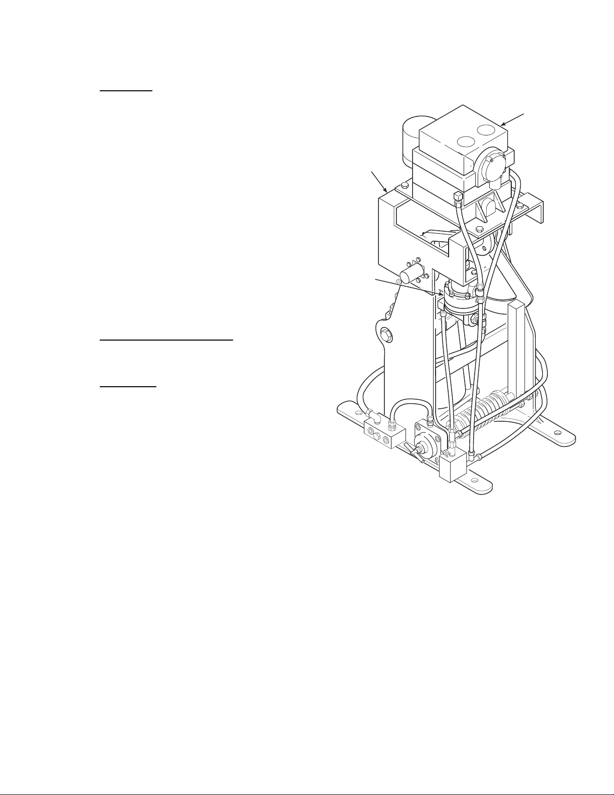
APPENDIX A. RETROFIT KIT INSTALLATION INSTRUCTIONS
A
A-1. FORWARD. This appendix addresses how to
replace an existing Hagan mechanical, pilot valve
type, positioner system with a PowerVUE system.
Removal, installation, and setup procedures are included. After completing this conversion, refer to the
base sections of this instruction bulletin for future
reference. The retrofit package includes a full instruction bulletin for the 4 x 5 PowerVUE Actuator.
This instruction bulletin provides important information including startup, calibration, troubleshooting,
and spare parts.
NOTE
The instruction bulletin for your existing
power positioner (pre-retrofit) should be
kept on file. Although Rosemount/Hagan
continues to improve products and update
instruction bulletins, the outdated instruction bulletin may still provide useful information.
A-2. COMPONENT CHECKLIST. A typical Power-
VUE 4 x 5 Actuator Retrofit Kit should contain the
items shown in Figure A-1.
DVC5000
ELECTRONIC
UNIT
MOUNTING
BRACKET
REVERSE
RELAY
A-3. OVERVIEW. The Rosemount PowerVUE 4 x 5
Actuator Retrofit Kit is designed for installation on
the Hagan 4 x 5 Torque Type Power Positioner. The
retrofit allows a 4-20 mA or fieldbus input signal sent
by a user’s process controller, to be received by the
DVC5000 electronic unit. The DVC5000 electronic
unit converts the input signal to a pneumatic output
pressure which is sent to the top of the pneumatic
cylinder and the reverse relay. The reverse relay
sends the appropriate inverse air pressure to the bottom of the pneumatic cylinder locking the piston in
place. A retrofitted PowerVUE 4 x 5 Actuator is
shown in Figure A-2.
29140031
Figure A-2. Retrofitted PowerVUE 4 x 5 Actuator
IB-102-204P
A-1
Page 72

A-4. MECHANICAL INSTALLATION.
Before performing any retrofit actions
on the actuator, shut off supply air, signal air, and any electrical supply or electronic signals to actuator. Isolate
actuator from all systems connected to
actuator. Severe injury or death may result from the large torque produced by
the actuator or from electrical shock.
a. Remove Actuator from Service.
3
2
1
1. Remove the actuator from service. Isolate
the actuator from the air supply by disconnecting the air supply or closing the supply
air shutoff valve (as applicable to the system). Isolate electrical power and electronic
signals to the actuator.
2. Open the drain cock on the air filter to exhaust the air supply from the actuator.
3. If the unit is equipped with a bypass valve
(1, Figure A-3), open the valve by turning it
fully counterclockwise.
4. If applicable, turn the air-lock release handle (2) fully clockwise to release the brake.
5. Position the actuator cylinder to mid-stroke
using manual lever (3).
29140021
1. Bypass Valve
2. Air Lock Release (Air Lock Option)
or Manual Lock (Manual Lock Option)
3. Manual Lever
Figure A-3. 4 x 5 Actuator
6. Remove actuator top cover, side panels, and
linkage as necessary to remove and install
parts.
NOTE
This retrofit pertains to the standard 4 x 5
actuators as well as the older units designated as Model 76. Step b pertains to the
standard unit and step c to Model 76.
IB-102-204P
A-2
Page 73

HEATING
A
ELEMENT
PORCELAIN
RECEPTACLE
6
5
2
NOTE:
THE OPTIONAL HEATER ASSEMBLY'S
PORCELAIN RECEPTACLE IS
MOUNTED AT HOLES "A". THE
THERMOSTAT (NOT SHOWN) MOUNTS
TO THE MAIN MOUNTING BRACKET.
6
5
1
AIR SUPPLY
MANIFOLD
PILOT
PILOT
VALV E
HEATER
BRACKET
A
MAIN MOUNTING
BRACKET
4
3
1
2
MANIFOLD
29140022
Figure A-4. Air Tubing and Compensator Assembly (Standard Unit)
b. Remove Positioner Components (Standard
2. Remove air tubing (1 through 6).
Units).
1. If the unit has a heater assembly, unscrew
the heating element, Figure A-4, and place
it aside for later reassembly.
NOTE
Air tubing has been illustrated for a unit
with a bypass valve.
Mounting bracket (5) is required to support
3. Remove cam (1, Figure A-5) and cam hub
(2).
4. If the unit has a thrust bearing (3), remove
the bearing and set aside for later use.
NOTE
the heater/thermostat assembly. If the unit
If the existing air tubing is to be reused,
disconnect the tubing only from those components being removed.
IB-102-204P
A-3
is not equipped with a heater/thermostat
but might be at a later date, leave the
bracket mounted or place in storage.
Page 74
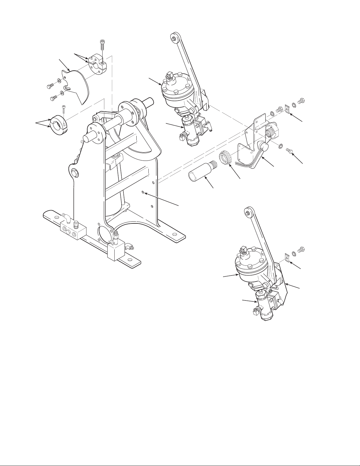
2
1
6
3
NOTE: IF THE UNIT IS EQUIPPED WITH A
HEATER/THERMOSTAT ASSEMBLY,
BRACKET (5) MUST REMAIN
MOUNTED TO THE FRAME.
7
5
10
9
4
11
A
VIEW A
4
6
5
7
Figure A-5. Removal of Positioner Components (Standard Unit)
IB-102-204P
A-4
437006
Page 75
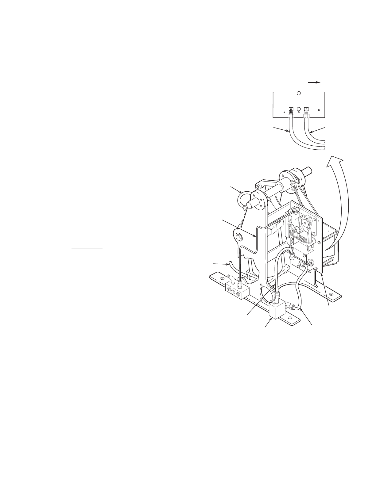
5. If the actuator is not equipped with a bypass
A
valve and has no heater/thermostat assembly, proceed as follows:
(a) Remove tube clamp (4) from mount-
ing bracket (5). Save the tube clamp
for reuse.
(b) Remove mounting bracket (5) with
receiver (6) and pilot valve/manifold
assembly (7) still mounted (View A,
Figure A-5).
4. Remove the mounting bracket with the positioner assembly and link attached.
5. Loosely mount the tube clamp on the outside of the frame at location “A”.
TOWARD
CYLINDER
(c) Loosely mount tube clamp (4) on the
outer side of the frame at location
“A”.
6. If the unit has a heater/thermostat assembly,
proceed as follows:
(a) Remove receptacle cover (10) to ac-
cess lower mounting bolt (11). Note
that heating element (9) was previously removed.
(b) Remove mounting bolts (11) and re-
ceiver (6) with attached pilot
valve/manifold assembly (7).
c. Remove Positioner Components (Model 76
Positioners).
NOTE
Air tubing has been illustrated for a unit
with a bypass valve.
1. Remove air tubing (1 through 4, Figure
A-6) and signal air line (5).
2
1
5
2
1
2. Disconnect link assembly, Figure A-7, from
the friction plate, and remove loose bushing.
4
BYPASS
VALV E
POSITIONER
ASSEMBLY
3
437011
3. Remove the tube clamp and set aside for
reuse.
Figure A-6. Air Tubing and Positioner
Assembly (Model 76)
IB-102-204P
A-5
Page 76

FRICTION
PLATE
BUSHING
LINK
ASSEMBLY
TUBE
CLAMP
MOUNTING
BRACKET
POSITIONER
ASSEMBLY
A
Figure A-7. Removal of Positioner Components (Model 76)
29140023
IB-102-204P
A-6
Page 77
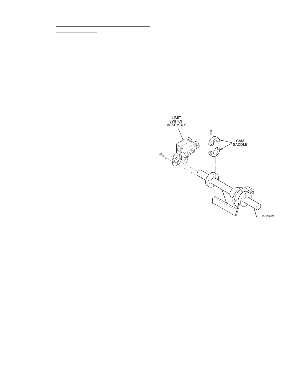
d. Remove Applicable Options (Both Standard
A
and Model 76 Units).
and remove from unit. Disconnect
signal wires from I/P converter.
NOTE
The limit switch assembly and cam saddles
may be reused. One cam saddle may be reused as a thrust bearing if limit switch assembly is not to be used.
The Electric Position Transmitter (EPT),
I/P converter, regulator and associated
brackets cannot be reused and must be removed.
The limit stop is not affected by the retrofit.
The heating element on the Model 76 cannot be reused. If a heater is desired for a
retrofitted Model 76, a new
heater/thermostat assembly and bracket
must be installed.
1. Remove limit switch assembly, Figure A-8.
If limit switch is to be used on retrofitted
unit, save for later remounting and leave
cam saddles in place. If not reusing limit
switch assembly, remove cam saddles. One
cam saddle may be reused as a thrust bearing.
(b) Remove the link assembly from the
EPT.
(c) Unclamp and remove the lever as-
sembly from the actuator shaft.
(d) Remove the mounting plate with the
EPT, I/P converter, and regulator still
attached.
(e) Remove both brackets from the posi-
tioner frame.
2. Remove the Electric Position Transmitter
(EPT), I/P converter, regulator, and associated items as follows. Refer to Figure A-9.
(a) Disconnect EPT cable from positioner
terminal block. Disconnect any air
lines from I/P converter and regulator
Figure A-8. Limit Switch Removal
IB-102-204P
A-7
Page 78
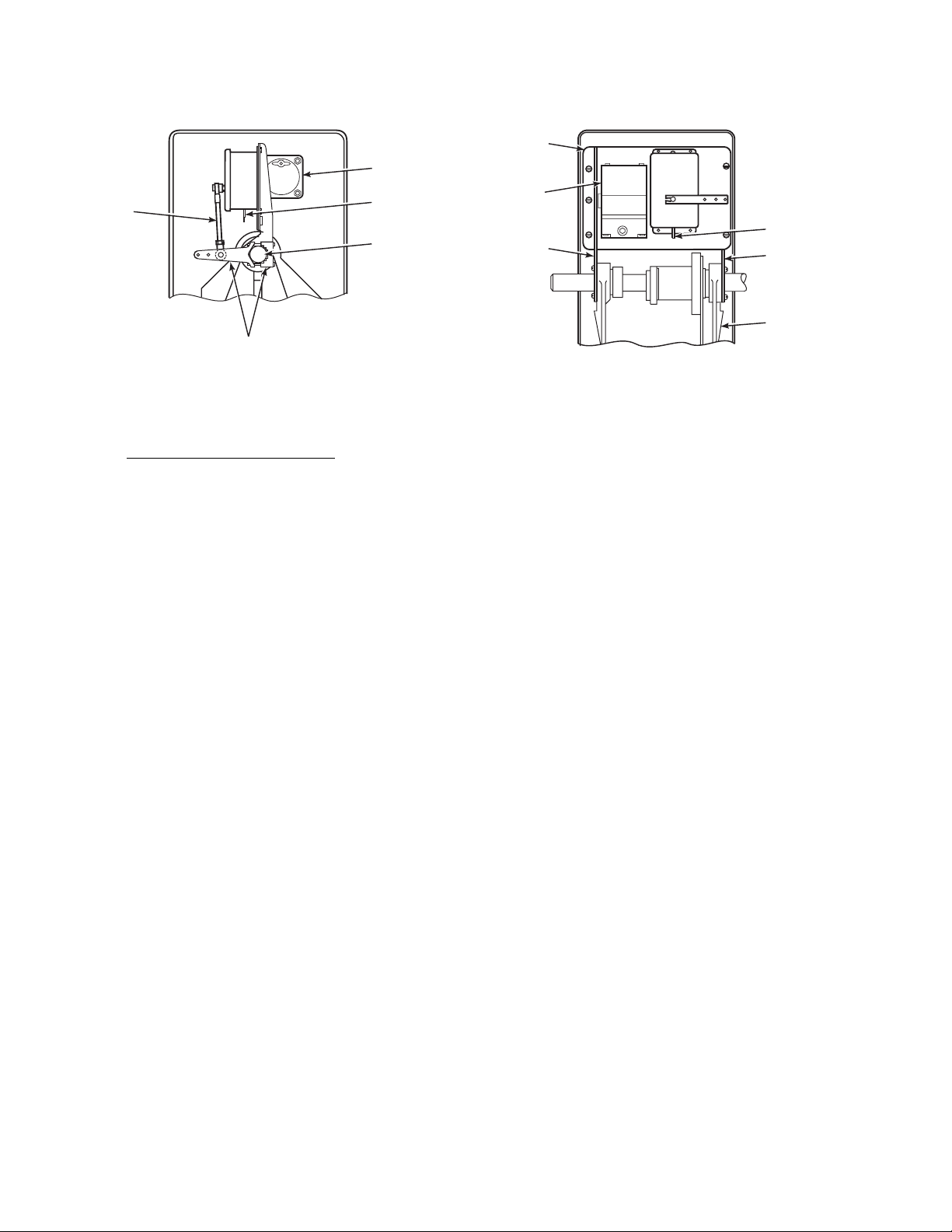
LINK
ASSEMBLY
SIDE VIEW DIRECT VIEW
MOUNTING
PLATE
EPT
LEVER
ASSEMBLY
REGULATOR
EPT
CABLE
ACTUATOR
SHAFT
I/P
CONVERTER
BRACKET
ACTUATOR
SHAFT
EPT
Figure A-9. Electric Position Transmitter (EPT) and I/P Converter Removal
EPT
CABLE
BRACKET
FRAME
29140025
e. Install PowerVUE Components.
NOTE
To ensure that PowerVUE components are
installed correctly, it is important to orient
the actuator. Position the unit so that the
pneumatic cylinder is located in the rear of
the frame when facing the actuator.
1. Position the unit so that the pneumatic cylinder is located in the rear of the frame
when facing the actuator, Figure A-10.
2. Install cam assembly to shaft, Figure A-10.
Ensure cam is mounted to left side of cam
shoe. Leave screw loose so cam rotates on
shaft for later adjustment.
NOTE
Before securing mounting bracket to actuator frame, ensure that pneumatic cylinder
operating lever does not hit the mounting
bracket. Contact Rosemount if sufficient
clearance does not exist.
3. Slide open end of mounting bracket over
left side of actuator shaft. The open end of
mounting bracket will be toward right side
of actuator. Check for operating clearance
between mounting bracket and pneumatic
cylinder operating lever.
4. Secure mounting bracket to actuator frame
with lock washers and screws provided,
Figure A-10.
5. Mount DVC5000 electronic unit to mounting bracket with bolts and washers provided, Figure A-10.
6. Adjust cam assembly on actuator shaft so
that the surface of the cam contacts
DVC5000 follower arm roller squarely.
Rotate the cam assembly so that the
DVC5000 follower arm just retracts
slightly. Tighten cam assembly to actuator
shaft.
7. Mount reverse relay to mounting bracket
with bolts provided, Figure A-10.
8. If using limit switch assembly, mount to
closed end of mounting bracket with limit
switch spacer, Figure A-11.
IB-102-204P
A-8
Page 79
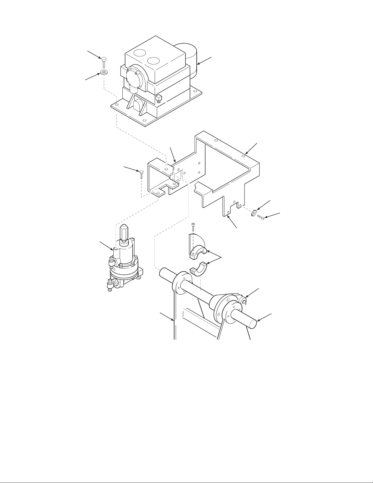
BOLT
A
WASHER
DVC 5000
ELECTRONIC
UNIT
REVERSE
RELAY
BOLT
ACTUATOR
FRAME
CLOSED
END
OPEN
END
CAM
ASSEMBLY
MOUNTING
BRACKET
LOCK
WASHER
SCREW
PNEUMATIC CYLINDER
MOUNTED IN REAR
OF ACTUATOR FRAME
WHEN FACING ACTUATOR
ACTUATOR
SHAFT
29140027
Figure A-10. PowerVUE Component Installation
IB-102-204P
A-9
Page 80

LIMIT SWITCH
ASSEMBLY
LIMIT SWITCH
SPACER
(b) Connect air line (1) from air manifold
to bottom of supply air T-fitting on
reverse relay.
(c) Connect air line (2) from top of sup-
ply air T-fitting on reverse relay to
fitting on DVC5000 air inlet.
(d) Connect air line (3) from DVC5000
air outlet to top of signal air T-fitting
on reverse relay.
(e) Connect air line (4) from bottom of
signal air T-fitting to fitting on bottom
of actuator cylinder.
MOUNTING BRACKET
(CLOSED END)
29140028
Figure A-11. Limit Switch Installation
f. Install PowerVUE System Air Tubing.
NOTE
Prior to connecting supply air to the actuator, purge the air system to remove all
moisture and debris.
1. For units without a bypass valve, refer to
Figure A-12 and proceed as follows:
Severe personal injury is possible. Do
not attempt to cut flexible air tubing
while supporting by hand. Place tubing
on a suitable surface prior to cutting.
Failure to take proper precautions can
lead to blade slippage and serious injury.
NOTE
Ensure each section of flexible air line is of
adequate length prior to cutting it from the
roll of tubing.
(a) Place roll of tubing on a suitable cut-
ting surface and, using a sharp knife,
carefully cut adequate lengths of air
line (1 through 5) from roll.
(f) Connect air line (5) from signal out
fitting on reverse relay to top of actuator cylinder.
2. For units with a bypass valve, refer to
Figure A-13 and proceed as follows:
Severe personal injury is possible. Do
not attempt to cut flexible air tubing
while supporting by hand. Place tubing
on a suitable surface prior to cutting.
Failure to take proper precautions can
lead to blade slippage and serious injury.
NOTE
Ensure each section of flexible air line is of
adequate length prior to cutting it from the
roll of tubing.
(a) Place roll of tubing on a suitable cut-
ting surface and, using a sharp knife,
carefully cut adequate lengths of air
line (1 through 7) from roll.
(b) Connect air line (1) from air manifold
to bottom of supply air T-fitting on
reverse relay.
(c) Connect air line (2) from top of sup-
ply air T-fitting on reverse relay to
fitting on DVC5000 air inlet.
IB-102-204P
A-10
Page 81

1
A
3
REVERSE
RELAY
DVC5000
ELECTRONIC
UNIT
2
AIR
MANIFOLD
5
1
4
ELECTRONIC
5
4
3
4 X 5 ACTUATOR
CYLINDER
DVC5000
UNIT
2
4 X 5 ACTUATOR
CYLINDER
SUPPLY
REVERSE
RELAY
1
AIR
AIR
MANIFOLD
29140029
Figure A-12. Air Piping Diagram (No Bypass Valve)
IB-102-204P
A-11
Page 82

1
3
REVERSE
RELAY
DVC5000
ELECTRONIC
UNIT
2
AIR
MANIFOLD
4
1
6
BYPASS
VALV E
DVC5000
ELECTRONIC
UNIT
7
4
3
7
4 X 5 ACTUATOR
CYLINDER
5
4 X 5
ACTUATOR
CYLINDER
BYPASS
VALV E
REVERSE
6
5
RELAY
1
Figure A-13. Air Piping Diagram (Bypass Valve)
IB-102-204P
A-12
2
SUPPLY
AIR
AIR
MANIFOLD
29140030
Page 83

(d) Connect air line (3) from DVC5000
A
air outlet to top of signal air T-fitting
on reverse relay.
(e) Connect air line (4) from bottom of
signal air T-fitting to top of T-fitting
on side of bypass valve.
(f) Connect air line (5) from side
T-fitting on bypass valve to bottom of
actuator cylinder.
(g) Connect air line (6) from signal out
fitting on reverse relay to top of
T-fitting on top of bypass valve.
(h) Connect air line (7) from side of
T-fitting on top of bypass valve to top
of actuator cylinder.
A-5. DVC5000 ELECTRONICS SETUP.
a. Introduction. Initial setup of the DVC5000 has
been performed at the factory. Refer to sections 4
and 5 of FIELDVUE DVC5000 Series Digital
Valve Controllers Instruction Manual for any additional tuning that may be required for particular applications.
A-6. CALIBRATION.
a. Reverse Relay Calibration. Refer to paragraph
4-1 to calibrate the reverse relay.
b. DVC5000 Calibration. Refer to sections 4 and
6 of FIELDVUE DVC5000 Series Digital Valve
Controllers Instruction Manual to calibrate the
DVC5000 electronic unit.
IB-102-204P
A-13/A-14
Page 84

3534
3618/11-01
Page 85

Appendix B
PowerVUE
FAN/DAMPER ACTUATOR
TORQUE TYPE 4 x 5
for use with DVC6000 Series
DIGITAL VALVE CONTROLLER
RETROFIT KIT
INSTALLATION INSTRUCTIONS
Instruction Bulletin IB-102-204P Rev. 1.0
Page 86

Page 87

TABLE OF CONTENTS
Section Page
B. RETROFIT KIT INSTALLATION INSTRUCTIONS........................................................B-1
B-1. FORWARD.. ..................................................................................................................B-1
B-2. COMPONENT CHECKLIST........................................................................................B-1
B-3. OVERVIEW...................................................................................................................B-1
B-4. MECHANICAL INSTALLATION............................................................................... B-2
B-5. DVC6000 ELECTRONICS SETUP...........................................................................B-12
B-6. DVC6000 CALIBRATION.......................................................................................... B-12
LIST OF ILLUSTRATIONS
Figure Page
B-1 PowerVUE 4 x 5 Retrofit Kit ..................................................................................................B-0
B-2 Retrofitted PowerVUE 4 x 5 Actuator.....................................................................................B-1
B-3 4 x 5 Actuator ..........................................................................................................................B-2
B-4 Air Tubing and Compensator Assembly (Standard Unit)........................................................B-3
B-5 Removal of Positioner Components (Standard Unit)...............................................................B-4
B-6 Air Tubing and Positioner Assembly (Model 76)....................................................................B-5
B-7 Removal of Positioner Components (Model 76) .....................................................................B-6
B-8 Limit Switch Removal.............................................................................................................B-7
B-9 Electric Position Transmitter (EPT) and I/P Converter Removal............................................B-8
B-10 PowerVUE Component Installation ........................................................................................B-9
B-11 Limit Switch Installation .......................................................................................................B-10
B-12 Air Piping Diagram (No Bypass Valve) ................................................................................B-11
B-13 Air Piping Diagram (Bypass Valve) ...................................................................................... B-12
IB-102-204P
i
Page 88

Table B-1. Model Number Matrix
PowerVUE Retrofit Kit - ORDERING INFORMATION
Select complete model number from the Model Number Matrix.
8 x 14
(1)
(2)
PVD 468R
PowerVUE Drive
Code Model
01 4 x 5
02
Code Digital Valve Controller
00
01
02
03
04
(3)
None
(4)
DVC6000
HART
Fieldbus
Fieldbus
(5)
DVC5000, with Basic Control Suite
(5)
DVC5000f, without Basic Control Suite
Other DVC Style Selected
(6)
Code EPT
00 None
01
Digital EPT and 2 Limit Contacts (HART versions only)
PVD 468R 02 02 01 EXAMPLE
NOTES:
(1)
Performance and specifications may vary from the published
specifications, depending on the age of the Hagan fan/damper
actuator and the quality of the DVC5000/6000 installation.
Setup and calibration is the responsibility of others. Faichild
reversing relay is included with or without (selection of)
DVC5000.
(2)
Some rilling and tapping required. Existing covers may be
modified in the field or a precut back cover can be selected
(reference P/N 4851B28G01).
(3)
Digital Valve Controller (DVC5000/6000) may be supplied by
others, but no performance quarantees for accuracy or speeds
of response are provided. Warranty for DVC5000/6000 will be
the responsibility of the provider. Tubing is provided, but is not
precut or preformed.
(4)
Standard arrangement calls for Model DVC6020f-516G60,
(5)
Standard arrangement calls for Model DVC5020f-216, certified
to FM as intrinsically safe, and Division 2. Other certifications
are available. Advanced diagnostics provided.
(4)
Designate other DVC5020/6020 model number as a note on
order.
(5)
Utilizes Moore Industries Site Programmable HART Alarm.
Default configuration:
1 analog output representing actuator travel
3 customer selectable position contacts
1 contact for Field Device Failure
Moore HART SPA may be configured in an intrinsically safe
arrangement through an IS barrier.
DVC5000/6000 Options:
Flameproof cable gland: ½” NPT (aluminum), EExd IIC
Cable entry adaptor (brass): ½” NPT M20 x 1.5 ISO
certified to FM as intrinsically safe, and Division 2. Other certifications are available. Advanced diagnostics provided.
(7)
½” NPT, PG 13.5
IB-102-204P
ii
Page 89

B
Figure B-1. PowerVUE 4 x 5 Retrofit Kit
IB-102-204P
iii/iv
Page 90

Page 91

APPENDIX B. RETROFIT KIT INSTALLATION INSTRUCTIONS
B
B-1. FORWARD. This appendix addresses how to
replace an existing Hagan mechanical, pilot valve
type, positioner system with a PowerVUE system.
Removal, installation, and setup procedures are included. After completing this conversion, refer to the
base sections of this instruction bulletin for future
reference. The retrofit package includes a full instruction bulletin for the 4 x 5 PowerVUE Actuator.
This instruction bulletin provides important information including startup, calibration, troubleshooting,
and spare parts.
NOTE
The instruction bulletin for your existing
power positioner (pre-retrofit) should be
kept on file. Although Rosemount/Hagan
continues to improve products and update
instruction bulletins, the outdated instruction bulletin may still provide useful information.
B-2. COMPONENT CHECKLIST. A typical Power-
VUE 4 x 5 Actuator Retrofit Kit should contain the
items shown in Figure B-1.
DVC6000
ELECTRONIC
UNIT
MOUNTING
BRACKET
B-3. OVERVIEW. The Rosemount PowerVUE 4 x 5
Actuator Retrofit Kit is designed for installation on
the Hagan 4 x 5 Torque Type Power Positioner. The
retrofit allows a 4-20 mA or fieldbus input signal sent
by a user’s process controller, to be received by the
DVC6000 electronic unit. The DVC6000 electronic
unit converts the input signal to a pneumatic output
pressure which is sent to the top or bottom of the
pneumatic cylinder, positioning and locking the piston in place. A retrofitted PowerVUE 4 x 5 Actuator
is shown in Figure B-2.
35340011
Figure B-2. Retrofitted PowerVUE 4 x 5 Actuator
IB-102-204P
B-1
Page 92

B-4. MECHANICAL INSTALLATION.
Before performing any retrofit actions
on the actuator, shut off supply air, signal air, and any electrical supply or electronic signals to actuator. Isolate
actuator from all systems connected to
actuator. Severe injury or death may result from the large torque produced by
the actuator or from electrical shock.
a. Remove Actuator from Service.
3
2
1
1. Remove the actuator from service. Isolate
the actuator from the air supply by disconnecting the air supply or closing the supply
air shutoff valve (as applicable to the system). Isolate electrical power and electronic
signals to the actuator.
2. Open the drain cock on the air filter to exhaust the air supply from the actuator.
3. If the unit is equipped with a bypass valve
(1, Figure B-3), open the valve by turning it
fully counterclockwise.
4. If applicable, turn the air-lock release handle (2) fully clockwise to release the brake.
5. Position the actuator cylinder to mid-stroke
using manual lever (3).
29140021
1. Bypass Valve
2. Air Lock Release (Air Lock Option)
or Manual Lock (Manual Lock Option)
3. Manual Lever
Figure B-3. 4 x 5 Actuator
6. Remove actuator top cover, side panels, and
linkage as necessary to remove and install
parts.
NOTE
This retrofit pertains to the standard 4 x 5
actuators as well as the older units designated as Model 76. Step b pertains to the
standard unit and step c to Model 76.
IB-102-204P
B-2
Page 93
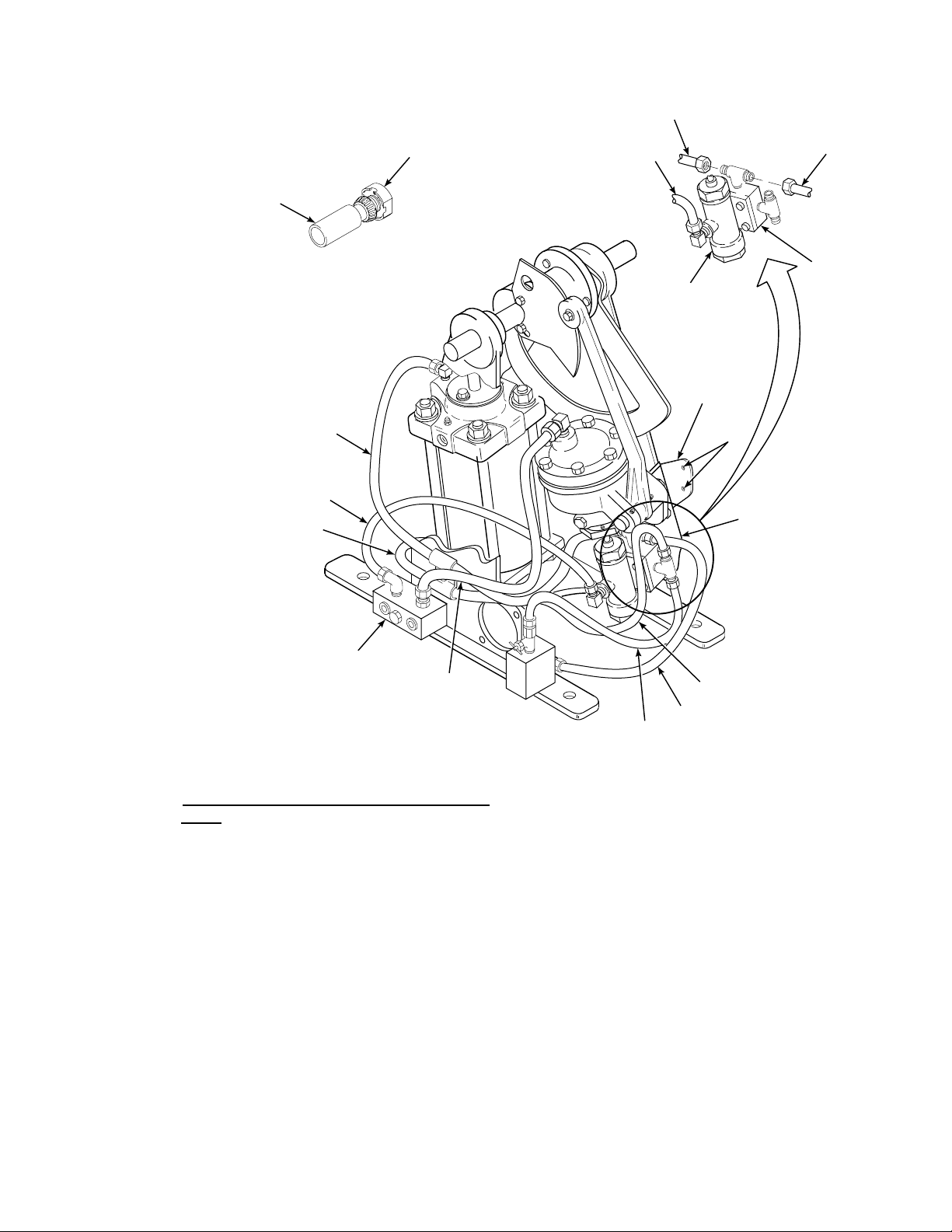
HEATING
B
ELEMENT
PORCELAIN
RECEPTACLE
6
5
2
NOTE:
THE OPTIONAL HEATER ASSEMBLY'S
PORCELAIN RECEPTACLE IS
MOUNTED AT HOLES "A". THE
THERMOSTAT (NOT SHOWN) MOUNTS
TO THE MAIN MOUNTING BRACKET.
6
5
1
AIR SUPPLY
MANIFOLD
PILOT
PILOT
VALV E
HEATER
BRACKET
A
MAIN MOUNTING
BRACKET
4
3
1
2
MANIFOLD
29140022
Figure B-4. Air Tubing and Compensator Assembly (Standard Unit)
b. Remove Positioner Components (Standard
2. Remove air tubing (1 through 6).
Units).
1. If the unit has a heater assembly, unscrew
the heating element, Figure B-4, and place
it aside for later reassembly.
NOTE
Air tubing has been illustrated for a unit
with a bypass valve.
Mounting bracket (5) is required to support
3. Remove cam (1, Figure B-5) and cam hub
(2).
4. If the unit has a thrust bearing (3), remove
the bearing and set aside for later use.
NOTE
the heater/thermostat assembly. If the unit
If the existing air tubing is to be reused,
disconnect the tubing only from those components being removed.
IB-102-204P
B-3
is not equipped with a heater/thermostat
but might be at a later date, leave the
bracket mounted or place in storage.
Page 94

2
1
6
3
NOTE: IF THE UNIT IS EQUIPPED WITH A
HEATER/THERMOSTAT ASSEMBLY,
BRACKET (5) MUST REMAIN
MOUNTED TO THE FRAME.
7
5
10
9
4
11
A
VIEW A
4
6
5
7
Figure B-5. Removal of Positioner Components (Standard Unit)
IB-102-204P
B-4
437006
Page 95

5. If the actuator is not equipped with a bypass
B
valve and has no heater/thermostat assembly, proceed as follows:
(a) Remove tube clamp (4) from mount-
ing bracket (5). Save the tube clamp
for reuse.
(b) Remove mounting bracket (5) with
receiver (6) and pilot valve/manifold
assembly (7) still mounted (View A,
Figure B-5).
4. Remove the mounting bracket with the positioner assembly and link attached.
5. Loosely mount the tube clamp on the outside of the frame at location “A”.
TOWARD
CYLINDER
(c) Loosely mount tube clamp (4) on the
outer side of the frame at location
“A”.
6. If the unit has a heater/thermostat assembly,
proceed as follows:
(a) Remove receptacle cover (10) to ac-
cess lower mounting bolt (11). Note
that heating element (9) was previously removed.
(b) Remove mounting bolts (11) and re-
ceiver (6) with attached pilot
valve/manifold assembly (7).
c. Remove Positioner Components (Model 76
Positioners).
NOTE
Air tubing has been illustrated for a unit
with a bypass valve.
1. Remove air tubing (1 through 4, Figure
B-6) and signal air line (5).
2
1
5
2
1
2. Disconnect link assembly, Figure B-7, from
the friction plate, and remove loose bushing.
4
BYPASS
VALV E
POSITIONER
ASSEMBLY
3
437011
3. Remove the tube clamp and set aside for
reuse.
Figure B-6. Air Tubing and Positioner
Assembly (Model 76)
IB-102-204P
B-5
Page 96

FRICTION
PLATE
BUSHING
LINK
ASSEMBLY
TUBE
CLAMP
MOUNTING
BRACKET
POSITIONER
ASSEMBLY
A
Figure B-7. Removal of Positioner Components (Model 76)
29140023
IB-102-204P
B-6
Page 97

d. Remove Applicable Options (Both Standard
B
and Model 76 Units).
and remove from unit. Disconnect
signal wires from I/P converter.
NOTE
The limit switch assembly and cam saddles
may be reused. One cam saddle may be reused as a thrust bearing if limit switch assembly is not to be used.
The Electric Position Transmitter (EPT),
I/P converter, regulator and associated
brackets cannot be reused and must be removed.
The limit stop is not affected by the retrofit.
The heating element on the Model 76 cannot be reused. If a heater is desired for a
retrofitted Model 76, a new heater/
thermostat assembly and bracket must be
installed.
1. Remove limit switch assembly, Figure B-8.
If limit switch is to be used on retrofitted
unit, save for later remounting and leave
cam saddles in place. If not reusing limit
switch assembly, remove cam saddles. One
cam saddle may be reused as a thrust bearing.
(b) Remove the link assembly from the
EPT.
(c) Unclamp and remove the lever as-
sembly from the actuator shaft.
(d) Remove the mounting plate with the
EPT, I/P converter, and regulator still
attached.
(e) Remove both brackets from the posi-
tioner frame.
2. Remove the Electric Position Transmitter
(EPT), I/P converter, regulator, and associated items as follows. Refer to Figure B-9.
(a) Disconnect EPT cable from positioner
terminal block. Disconnect any air
lines from I/P converter and regulator
Figure B-8. Limit Switch Removal
IB-102-204P
B-7
Page 98

LINK
ASSEMBLY
SIDE VIEW DIRECT VIEW
MOUNTING
PLATE
EPT
LEVER
ASSEMBLY
REGULATOR
EPT
CABLE
ACTUATOR
SHAFT
I/P
CONVERTER
BRACKET
ACTUATOR
SHAFT
EPT
Figure B-9. Electric Position Transmitter (EPT) and I/P Converter Removal
EPT
CABLE
BRACKET
FRAME
29140025
e. Install PowerVUE Components.
NOTE
To ensure that PowerVUE components are
installed correctly, it is important to orient
the actuator. Position the unit so that the
pneumatic cylinder is located in the rear of
the frame when facing the actuator.
1. Position the unit so that the pneumatic cylinder is located in the rear of the frame
when facing the actuator, Figure B-10.
2. Install cam assembly to shaft, Figure B-10.
Ensure cam is mounted to left side of cam
shoe. Leave screw loose so cam rotates on
shaft for later adjustment.
NOTE
Before securing mounting bracket to actuator frame, ensure that pneumatic cylinder
operating lever does not hit the mounting
bracket. Contact Rosemount if sufficient
clearance does not exist.
3. Slide open end of mounting bracket over
left side of actuator shaft. The open end of
mounting bracket will be toward right side
of actuator. Check for operating clearance
between mounting bracket and pneumatic
cylinder operating lever.
4. Secure mounting bracket to actuator frame
with lock washers and screws provided,
Figure B-10.
5. Mount DVC6000 electronic unit to mounting bracket with bolts and washers provided, Figure B-10.
6. Adjust cam assembly on actuator shaft so
that the surface of the cam contacts
DVC6000 follower arm roller squarely.
Rotate the cam assembly so that the
DVC6000 follower arm just retracts
slightly. Tighten cam assembly to actuator
shaft.
7. If using limit switch assembly, mount to
closed end of mounting bracket with limit
switch spacer, Figure B-11.
IB-102-204P
B-8
Page 99

BOL T
B
WASHER
DVC 6000
ELECTRONIC
UNIT
ACTUATOR
FRAME
CLOSED
END
OPEN
END
CAM
ASSEMBLY
MOUNTING
BRACKET
LOCK
WASHER
SCREW
PNEUMATIC CYLINDER
MOUNTED IN REAR
OF ACTUATOR FRAME
WHEN FACING A CTUATOR
ACTUATOR
SHAFT
35340012
Figure B-10. PowerVUE Component Installation
IB-102-204P
B-9
Page 100

LIMIT SWITC H
ASSEMBLY
LIMIT SWITC H
SPACER
MOUNTING BRACKET
(CLOSED END)
29140028
Figure B-11. Limit Switch Installation
f. Install PowerVUE System Air Tubing.
(c) Connect air line (2) from top actuator
cyclinder fitting to port A fitting (top
fitting) on DVC6000 electronic unit.
(d) Connect air line (3) from bottom ac-
tuator cyclinder port to port B fitting
(bottom fitting) on DVC6000 electronic unit.
2. For units with a bypass valve, refer to
Figure B-13 and proceed as follows:
Severe personal injury is possible. Do
not attempt to cut flexible air tubing
while supporting by hand. Place tubing
on a suitable surface prior to cutting.
Failure to take proper precautions can
lead to blade slippage and serious injury.
NOTE
Prior to connecting supply air to the actuator, purge the air system to remove all
moisture and debris.
1. For units without a bypass valve, refer to
Figure B-12 and proceed as follows:
Severe personal injury is possible. Do
not attempt to cut flexible air tubing
while supporting by hand. Place tubing
on a suitable surface prior to cutting.
Failure to take proper precautions can
lead to blade slippage and serious injury.
NOTE
Ensure each section of flexible air line is of
adequate length prior to cutting it from the
roll of tubing.
NOTE
Ensure each section of flexible air line is of
adequate length prior to cutting it from the
roll of tubing.
(a) Place roll of tubing on a suitable cut-
ting surface and, using a sharp knife,
carefully cut adequate lengths of air
line (1 through 5) from roll.
(b) Connect air line (1) from air manifold
to supply air fitting (center fitting) on
DVC6000 electronic unit.
(c) Connect air line (2) from T-fitting on
side of bypass valve to port B fitting
(bottom fitting) on DVC6000 electronic unit.
(d) Connect air line (3) from T-fitting on
top of bypass valve to port A fitting
(top fitting) on DVC6000 electronic
unit.
(a) Place roll of tubing on a suitable cut-
ting surface and, using a sharp knife,
carefully cut adequate lengths of air
line (1 through 3) from roll.
(b) Connect air line (1) from air manifold
to supply air fitting (center fitting) on
DVC6000 electronic unit.
IB-102-204P
(e) Connect air line (4) from T-fitting on
top of bypass valve to top actuator
cylinder fitting.
(f) Connect air line (5) from side
T-fitting on bypass valve to bottom
actuator cylinder fitting.
B-10
 Loading...