

Page 1

Instruction Manual
IM-106-350, Rev 2.3
October 2008
Oxymitter 5000
Oxygen Transmitter
http://www.raihome.com
Page 2

Page 3

HIGHLIGHTS OF CHANGES
Effective September, 2006 Rev 2.0
Page Summary
General Reformatted entire manual from a two column layout. Replaced SPS 4000 information
with SPS 4001B information. Removed all references to JIS specifications. Added
information pertaining to the Local Operator Interface (LOI). Added information pertaining
to the remote electronics option.
Cover Updated photo.
Page TOC-4 Removed List of Illustrations and List of Tables from the table of contents in Rev 1.6.
Page i Moved from backside of cover in Rev 1.4.
Page 1-2 Updated Figure 1-1, Typical System Package to show SPS 4001B and remote electronics.
Page 1-5 Updated Figure 1-2, Oxymitter 5000 AutoCalibration System Options to show the SPS
4001B.
Page 1-6 Added Figure 1-3, Membrane Keypad and Figure 1-4, Local Operator Interface (LOI).
Added step 4 under System Features.
Page 1-7 Removed step 6 under System Features from Rev 1.6.
Page 1-10 Added Figure 1-7, Typical System Installation – Oxymitter 5000 with Remote Electronics.
Page 1-11 Removed Figure 1-5, SPS 4000 from Rev 1.6.
Page 1-14 Updated Figure 1-11, Abrasive Shield Assembly.
Page 1-15 thru 1-16 Updated the specifications table.
Page 1-17 thru 1-18 Updated Table 1-1, Product Matrix.
Page 1-19 Removed Table 1-5, Single Probe Autocalibration Sequencer Coding from Rev 1.6.
Page 2-1 Added second and third Warning.
Page 2-3 Removed Figure 2-2, Oxymitter 5000 Installation (with SPS 4000) from Rev 1.6.
Page 2-4 Added Figure 2-2, Oxymitter 5000 Remote Electronics Installation.
Page 2-10 Added remote electronics information and Figure 2-8, Remote Electronics Mounting.
Page 2-11 Added both Notes and fourth W arning.
Page 2-12 Removed Figure 2-9, Terminal Block from Rev 1.6.
Page 2-13 Added Figure 2-10, Electrical Installation - Oxymitter 5000 with Integral Electronics.
Page 2-14 Removed information under Electrical installation (For Oxymitter 5000 with SPS 4000),
along with Figures 2-9 and 2-10 from Rev 1.6.
Page 2-14 thru 2-15 Added information under Electrical Installation (with Remote Electronics).
Page 2-16 Added Figure 2-11, Electrical Installation - Oxymitter 5000 with Remote Electronics.
Page 2-17 Added information regarding the installation of the interconnecting cable.
page 2-19 Added body text under IMPS 4000 Connections and SPS 4001B Connections.
Page 3-1 Revised procedural steps under Terminal Block Wiring.
Page 4

HIGHLIGHTS OF CHANGES (CONTINUED)
Effective September, 2006 Rev 2.0 (Continued)
Page Summary
Page 3-2 Added Caution.
Page 4-1 thru 4-6 Added Section 4, Configuration of Oxymitter 5000 with LOI.
Page 5-1 thru 5-4 Pages 3-6 thru 3-10 in Section 3, Startup and Operation of Rev 1.6 was moved to Section
5, Startup and Operation of Oxymitter 5000 with Membrane Keypad.
Page 6-1 thru 6-10 Added Section 6, Startup and Operation of Oxymitter 5000 with LOI.
Page 7-1 Added body text under Overview.
Page 7-2 Added Figure 7-1, O2 Sensor mV Reading vs. % O2 at 736°C (Reference Air, 20.9% O2).
Page 7-4 Added Figure 7-2, Diagnostic LEDs.
Page 7-6 Removed Table 5-2, Calibration Fault Troubleshooting and Added Table 7-2,
Diagnostic/Unit Alarm Fault Definitions - LOI.
Page 7-7 thru 7-21 Added the LOI in Figures 7-3 thru 7-17 with descriptive text to accompany each figure.
Page 7-22 and 7-23 Added text and Figure 7-18, Probe Leakage Paths.
Page 8-0 Moved the "Calibration Record for Rosemount Analytical in Situ O2 Probe", from the back
of the section to the front.
Page 8-6 and 8-7 Added information under the Calibration with LOI heading.
Page 8-7 Removed information regarding LED Status Indicators and Table 4-1, Diagnostic/Unit
Alarms from Rev 1.6.
Page 8-8 thru 8-21 Updated procedural steps throughout section.
Page 8-9 Removed Figure 4-4, Terminal Block from Rev 1.6. Updated Figure 8-3, Oxymitter 5000
with Integral Electronics - Exploded View, to show the LOI module and Window Cover.
Page 8-10 Added Figure 8-4, Oxymitter 5000 with Remote Electronics - Exploded View.
Page 8-15 Revised information under Heater Strut Replacement.
Page 8-17 Added Figure 8-9, Probe to Probe Head Assembly - Remote Electronics Only
Page 8-20 Revised Replacement Procedure for Ceramic Diffusion Element Replacement.
Page 8-21 Added Figure 8-12, Contact and Thermocouple Assembly Replacement.
Page 8-22 Removed information regarding the SPS 4000 Maintenance and Component
Replacement from pages 4-17 thru 4-24 in Rev 1.6.
Page 10-5 Added Figure 10-5, Catalyst Regene ration and corresponding text.
Page A-1 thru A-14 Moved Safety Instructions P-3 thru P-11 from the preface in Rev 1.6 to Appendix A in Rev
2.0.
Page B-1 Moved Section 10, Return of Material from Rev 1.6 to Appendix B in Rev 2.0.
Page C-1 thru C-6 Moved Appendix A in Rev 1.6 to Appendix C in Rev 2.0.
Page D-1 thru D-10 Moved Appendix B in Rev 1.6 to Appendix D in Rev 2.0.
Page E-1 Moved Appendix C in Rev 1.6 to Appendix E in Rev 2.0.
Page 5

HIGHLIGHTS OF CHANGES (CONTINUED)
Effective January, 2007 Rev 2.1
Page Summary
General Revised reference air specifications to read 1 l/min (2 scfh) throughout the manual.
Page 7-1 thru 7-6 Added section 7.
Page 8-22 Added the paragraph and procedural steps after 'Heater Not Open, but Unable to Reach
736°C Setpoint.
Page 11-1 Added Model 375 Handheld Communicator information.
Page 11-2 Added Asset Management Solutions (AMS) information.
Page A-2 thru A-24 Added note 11 to the safety data section. Added new language translations.
Page B-1 Updated the return of materials address.
Back cover Updated the address blocks.
Page Summary
Page 6-4 Added note regarding cleaning the LOI screen before use.
'
Effective July 2008 Rev. 2.2
Page 6

HIGHLIGHTS OF CHANGES (CONTINUED)
Effective October 2008 Rev. 2.3
Page Summary
All pages Changed revision level and date to reflect this revision.
General Added new Section 8 PlantWeb Alerts; updated section numbers of remaining sections.
Updated all page number and section number referen ces to renumbered sections.
Revised all references to "Model 375 Handheld Communicator" to read "Field
Communicator."
Page xi Revised e-mail address to read "@emerson.com."
Page 1-15 Deleted Standard range data from specifications listing.
Page 2-8 Revised Figure 2-6.
Page 2-16 Revised Figure 2-11.
Page 3-2 Revised first paragraph of Oxymitter 5000 Configuration discussion.
Page 3-2 Revised Figure 3-2 and related text.
Page 3-5 Revised Recommended Configuration discussion.
Page 4-1 Deleted reference to "Hazardous Area" Oxymitter.
Page 4-2 Revised first paragraph of Oxymitter 5000 Configuration discussion.
Page 4-3 Revised Figure 4-2 and related text.
Page 4-5 Revised Recommended Configuration discussion
Page 6-7 Revised "Analog" description for "SYSTEM/Input/Output:.
Page 7-1 Revised "Overview" discussion.
Page 7-2 Revised Figure 7-1.
Page 7-3 Deleted "Logic I/O Configurations" discussion and Table 7-1.
Page 7-4 Revised Figure 7-2.
Pages 8-1 through
8-10
Page 9-6 Revised Table 9-1 and Table 9-2.
Page 9-11 Added new Fault 5, Line Frequency Error discussion and illustration. Updated remaining
Page 9-23 Added new Fault 18, SPS Handshake Failed discussion and illustration.
Pages 9-24 and 9-25 Revised "Calibration Passes ..." discussion.
Page C-1 Revised tabular Fieldbus Parameters listing.
Page C-5 and C-6 Relocated previous Tables C-4 and C-5 to Appendix D. Added new Table C-4, Operating
Page D-1 Revised to incorporate "Introduction" and new table D-1 (relocated from Appendix C).
Page D-2 Revised to incorporate new table D-2 (revised and relocated from Appendix C).
Page D-4 Revised "Simulation" discussion.
Back Cover Revised e-mail addresses to read "@emerson.com."
Added new PlantWeb Alerts section.
fault and figure numbers in this section.
Modes.
Page 7

Instruction Manual
IM-106-350, Rev 2.3
October 2008
Oxymitter 5000
Table of Contents
Essential Instructions . . . . . . . . . . . . . . . . . . . . . . . . . . . . . . . . . . . . . . . . i
SECTION i
Introduction
SECTION 1
Description and
Specifications
Preface. . . . . . . . . . . . . . . . . . . . . . . . . . . . . . . . . . . . . . . . . . . . . . . . . . iv
Definitions . . . . . . . . . . . . . . . . . . . . . . . . . . . . . . . . . . . . . . . . . . . . . . . iv
Symbols . . . . . . . . . . . . . . . . . . . . . . . . . . . . . . . . . . . . . . . . . . . . . . . . . iv
Oxymitter 5000 with Fieldbus Communications. . . . . . . . . . . . . . . . . . . v
What You Need To Know. . . . . . . . . . . . . . . . . . . . . . . . . . . . . . . . . . . . v
Can You Use the Quick Start Guide? . . . . . . . . . . . . . . . . . . . . . . . . . . v
Quick Start Guide for Oxymitter 5000 Systems . . . . . . . . . . . . . . . . . . viii
Quick Reference Guide Manual Calibration Instructions . . . . . . . . . . . . ix
Component Checklist. . . . . . . . . . . . . . . . . . . . . . . . . . . . . . . . . . . . . .1-1
System Overview . . . . . . . . . . . . . . . . . . . . . . . . . . . . . . . . . . . . . . . . .1-1
Scope . . . . . . . . . . . . . . . . . . . . . . . . . . . . . . . . . . . . . . . . . . . . . . .1-1
FOUNDATION Fieldbus Technology . . . . . . . . . . . . . . . . . . . . . . .1-3
System Description. . . . . . . . . . . . . . . . . . . . . . . . . . . . . . . . . . . . .1-3
System Configuration . . . . . . . . . . . . . . . . . . . . . . . . . . . . . . . . . . .1-4
System Features. . . . . . . . . . . . . . . . . . . . . . . . . . . . . . . . . . . . . . .1-5
Handling the Oxymitter 5000 . . . . . . . . . . . . . . . . . . . . . . . . . . . . .1-7
System Considerations. . . . . . . . . . . . . . . . . . . . . . . . . . . . . . . . . .1-7
IMPS 4000 (Optional). . . . . . . . . . . . . . . . . . . . . . . . . . . . . . . . . . . . .1-11
SPS 4001B (Optional) . . . . . . . . . . . . . . . . . . . . . . . . . . . . . . . . . . . .1-11
Mounting . . . . . . . . . . . . . . . . . . . . . . . . . . . . . . . . . . . . . . . . . . . .1-11
Operation . . . . . . . . . . . . . . . . . . . . . . . . . . . . . . . . . . . . . . . . . . .1-11
Probe Options . . . . . . . . . . . . . . . . . . . . . . . . . . . . . . . . . . . . . . . . . .1-12
Diffusion Elements . . . . . . . . . . . . . . . . . . . . . . . . . . . . . . . . . . . .1-12
Abrasive Shield Assembly . . . . . . . . . . . . . . . . . . . . . . . . . . . . . .1-13
Specifications. . . . . . . . . . . . . . . . . . . . . . . . . . . . . . . . . . . . . . . . . . .1-15
SECTION 2
Installation
Mechanical Installation. . . . . . . . . . . . . . . . . . . . . . . . . . . . . . . . . . . . .2-2
Selecting Location. . . . . . . . . . . . . . . . . . . . . . . . . . . . . . . . . . . . . .2-2
Probe Installation . . . . . . . . . . . . . . . . . . . . . . . . . . . . . . . . . . . . . .2-2
Remote Electronics Installation. . . . . . . . . . . . . . . . . . . . . . . . . . .2-10
Electrical Installation (with Integral Electronics). . . . . . . . . . . . . . . . .2-11
Connect Line Voltage . . . . . . . . . . . . . . . . . . . . . . . . . . . . . . . . . .2-11
Electrical Installation (with Remote Electronics) . . . . . . . . . . . . . . . .2-14
Connect Line Voltage . . . . . . . . . . . . . . . . . . . . . . . . . . . . . . . . . .2-14
Install Interconnecting Cable. . . . . . . . . . . . . . . . . . . . . . . . . . . . .2-17
Pneumatic Installation . . . . . . . . . . . . . . . . . . . . . . . . . . . . . . . . . . . .2-17
Reference Air Package. . . . . . . . . . . . . . . . . . . . . . . . . . . . . . . . .2-17
Calibration Gas . . . . . . . . . . . . . . . . . . . . . . . . . . . . . . . . . . . . . . .2-18
IMPS 4000 Connections . . . . . . . . . . . . . . . . . . . . . . . . . . . . . . . . . .2-19
SPS 4001B Connections . . . . . . . . . . . . . . . . . . . . . . . . . . . . . . . . . .2-19
TOC-1
Page 8

Oxymitter 5000
Instruction Manual
IM-106-350, Rev. 2.3
October 2008
SECTION 3
Configuration of
Oxymitter 5000 with
Membrane Keypad
SECTION 4
Configuration of
Oxymitter 5000 with LOI
SECTION 5
Startup and Operation of
Oxymitter 5000 with
Membrane Keypad
SECTION 6
Startup and Operation of
Oxymitter 5000 with LOI
Verify Installation . . . . . . . . . . . . . . . . . . . . . . . . . . . . . . . . . . . . . . . . . 3-1
Mechanical Installation . . . . . . . . . . . . . . . . . . . . . . . . . . . . . . . . . . 3-1
Terminal Block Wiring. . . . . . . . . . . . . . . . . . . . . . . . . . . . . . . . . . . 3-1
Oxymitter 5000 Configuration. . . . . . . . . . . . . . . . . . . . . . . . . . . . . 3-2
Logic I/O . . . . . . . . . . . . . . . . . . . . . . . . . . . . . . . . . . . . . . . . . . . . . . . 3-4
Recommended Configuration. . . . . . . . . . . . . . . . . . . . . . . . . . . . . 3-5
Verify installation . . . . . . . . . . . . . . . . . . . . . . . . . . . . . . . . . . . . . . . . . 4-1
Mechanical Installation . . . . . . . . . . . . . . . . . . . . . . . . . . . . . . . . . . 4-1
Terminal Block Wiring. . . . . . . . . . . . . . . . . . . . . . . . . . . . . . . . . . . 4-1
Oxymitter 5000 Configuration. . . . . . . . . . . . . . . . . . . . . . . . . . . . . 4-2
Logic I/O . . . . . . . . . . . . . . . . . . . . . . . . . . . . . . . . . . . . . . . . . . . . . . . 4-4
Recommended Configuration. . . . . . . . . . . . . . . . . . . . . . . . . . . . . 4-5
Power Up. . . . . . . . . . . . . . . . . . . . . . . . . . . . . . . . . . . . . . . . . . . . . . . 5-1
Operation. . . . . . . . . . . . . . . . . . . . . . . . . . . . . . . . . . . . . . . . . . . . . . . 5-2
Overview. . . . . . . . . . . . . . . . . . . . . . . . . . . . . . . . . . . . . . . . . . . . . 5-2
Power Up. . . . . . . . . . . . . . . . . . . . . . . . . . . . . . . . . . . . . . . . . . . . . . . 6-1
Start Oxymitter 5000 Calibration . . . . . . . . . . . . . . . . . . . . . . . . . . . . . 6-3
Navigating the Local Operator Interface . . . . . . . . . . . . . . . . . . . . . . . 6-3
Overview. . . . . . . . . . . . . . . . . . . . . . . . . . . . . . . . . . . . . . . . . . . . . 6-3
Lockout. . . . . . . . . . . . . . . . . . . . . . . . . . . . . . . . . . . . . . . . . . . . . . 6-3
LOI Key Designations . . . . . . . . . . . . . . . . . . . . . . . . . . . . . . . . . . . . . 6-4
LOI Menu Tree. . . . . . . . . . . . . . . . . . . . . . . . . . . . . . . . . . . . . . . . . . . 6-4
Oxymitter 5000 Setup at the LOI. . . . . . . . . . . . . . . . . . . . . . . . . . . . . 6-6
LOI Installation. . . . . . . . . . . . . . . . . . . . . . . . . . . . . . . . . . . . . . . . . . . 6-9
Oxymitter 5000 Test Points . . . . . . . . . . . . . . . . . . . . . . . . . . . . . . . . 6-10
SECTION 7
Field Communicator
SECTION 8
PlantWeb Alerts
TOC-2
Overview . . . . . . . . . . . . . . . . . . . . . . . . . . . . . . . . . . . . . . . . . . . . . . . 7-1
Fieldbus Terminal Block Connections . . . . . . . . . . . . . . . . . . . . . . . . . 7-1
Off-Line and On-Line Operations. . . . . . . . . . . . . . . . . . . . . . . . . . . . . 7-2
Fieldbus Menu Tree. . . . . . . . . . . . . . . . . . . . . . . . . . . . . . . . . . . . . . . 7-3
FOUNDATION Fieldbus O
Introduction . . . . . . . . . . . . . . . . . . . . . . . . . . . . . . . . . . . . . . . . . . . . . 8-1
PlantWeb Alert Groups . . . . . . . . . . . . . . . . . . . . . . . . . . . . . . . . . . . . 8-1
PlantWeb Alert Configuration . . . . . . . . . . . . . . . . . . . . . . . . . . . . . . . 8-2
PlantWeb Priorities. . . . . . . . . . . . . . . . . . . . . . . . . . . . . . . . . . . . . 8-3
Fieldbus/PWA Simulate. . . . . . . . . . . . . . . . . . . . . . . . . . . . . . . . . . . . 8-3
Configure Simulation from AMS . . . . . . . . . . . . . . . . . . . . . . . . . . . 8-3
Configure Simulation with the Model 375 Field Communicator . . . 8-6
Parameter Descriptions . . . . . . . . . . . . . . . . . . . . . . . . . . . . . . . . . . . . 8-7
CAL Method . . . . . . . . . . . . . . . . . . . . . . 7-5
2
Page 9

Instruction Manual
IM-106-350, Rev 2.3
October 2008
Oxymitter 5000
SECTION 9
Troubleshooting
SECTION 10
Maintenance and
Service
Overview . . . . . . . . . . . . . . . . . . . . . . . . . . . . . . . . . . . . . . . . . . . . . . .9-1
General . . . . . . . . . . . . . . . . . . . . . . . . . . . . . . . . . . . . . . . . . . . . . . . .9-3
Alarm Indications . . . . . . . . . . . . . . . . . . . . . . . . . . . . . . . . . . . . . . . . .9-3
Alarm Contacts. . . . . . . . . . . . . . . . . . . . . . . . . . . . . . . . . . . . . . . . . . .9-4
Identifying and Correcting Alarm Indications . . . . . . . . . . . . . . . . . . . .9-5
Heater Not Open, but Unable to Reach 736°C Setpoint . . . . . . . . . .9-23
Calibration Passes but Still Reads Incorrectly . . . . . . . . . . . . . . . . . .9-23
Probe Passes Calibration, O2 Still Reads High . . . . . . . . . . . . . .9-23
Probe Passes Calibration, O2 Still Reads Low. . . . . . . . . . . . . . .9-24
How do I detect a plugged diffuser? . . . . . . . . . . . . . . . . . . . . . . .9-25
Can I calibrate a badly plugged diffuser? . . . . . . . . . . . . . . . . . . .9-25
Overview . . . . . . . . . . . . . . . . . . . . . . . . . . . . . . . . . . . . . . . . . . . . . .10-1
Calibration with Keypad . . . . . . . . . . . . . . . . . . . . . . . . . . . . . . . . . . .10-1
Automatic Calibration . . . . . . . . . . . . . . . . . . . . . . . . . . . . . . . . . .10-2
Semi-Automatic Calibration . . . . . . . . . . . . . . . . . . . . . . . . . . . . .10-3
Manual Calibration with Membrane Keypad . . . . . . . . . . . . . . . . .10-3
FOUNDATION Fieldbus O
Calibration with LOI . . . . . . . . . . . . . . . . . . . . . . . . . . . . . . . . . . . . . .10-6
Oxymitter 5000 Repair . . . . . . . . . . . . . . . . . . . . . . . . . . . . . . . . . . . .10-8
Removal and Replacement of Probe . . . . . . . . . . . . . . . . . . . . . .10-8
Replace Entire Integral Electronics (with Housing). . . . . . . . . . .10-11
Electronic Assembly Replacement . . . . . . . . . . . . . . . . . . . . . . .10-12
Terminal Block Replacement . . . . . . . . . . . . . . . . . . . . . . . . . . .10-13
Fuse Replacement . . . . . . . . . . . . . . . . . . . . . . . . . . . . . . . . . . .10-13
Entire Probe Replacement (Excluding Probe Head). . . . . . . . . .10-14
Heater Strut Replacement . . . . . . . . . . . . . . . . . . . . . . . . . . . . .10-15
Cell Replacement . . . . . . . . . . . . . . . . . . . . . . . . . . . . . . . . . . . .10-17
Ceramic Diffusion Element Replacement. . . . . . . . . . . . . . . . . .10-20
CAL Method. . . . . . . . . . . . . . . . . . . . . .10-5
2
SECTION 11
Replacement Parts
SECTION 12
Optional
Accessories
APPENDIX A
Safety Data
APPENDIX B
Return of Material
Probe Replacement Parts . . . . . . . . . . . . . . . . . . . . . . . . . . . . . . . . .11-1
Electronics Replacement Parts . . . . . . . . . . . . . . . . . . . . . . . . . . . . .11-6
Model 375 Field Communicator . . . . . . . . . . . . . . . . . . . . . . . . . . . . .12-1
Asset Management Solutions (AMS) . . . . . . . . . . . . . . . . . . . . . . . . .12-2
By-Pass Packages. . . . . . . . . . . . . . . . . . . . . . . . . . . . . . . . . . . . . . .12-2
IMPS 4000 Intelligent Multiprobe Test Gas Sequencer . . . . . . . . . . .12-3
SPS 4001B Single Probe Autocalibration Sequencer . . . . . . . . . . . .12-4
Calibration Gas. . . . . . . . . . . . . . . . . . . . . . . . . . . . . . . . . . . . . . .12-5
O
2
Catalyst Regeneration . . . . . . . . . . . . . . . . . . . . . . . . . . . . . . . . . . . .12-6
Safety Instructions . . . . . . . . . . . . . . . . . . . . . . . . . . . . . . . . . . . . . . . A-2
Safety Data Sheet for Ceramic Fiber Products . . . . . . . . . . . . . . . . A-24
Returning Material . . . . . . . . . . . . . . . . . . . . . . . . . . . . . . . . . . . . . . . B-1
TOC-3
Page 10

Oxymitter 5000
Instruction Manual
IM-106-350, Rev. 2.3
October 2008
APPENDIX C
Fieldbus
Parameter
Description
APPENDIX D
Analog Input (AI)
Function Block
Fieldbus Parameters. . . . . . . . . . . . . . . . . . . . . . . . . . . . . . . . . . . . . . C-1
Introduction. . . . . . . . . . . . . . . . . . . . . . . . . . . . . . . . . . . . . . . . . . . . . D-1
Simulation. . . . . . . . . . . . . . . . . . . . . . . . . . . . . . . . . . . . . . . . . . . . . . D-4
Filtering. . . . . . . . . . . . . . . . . . . . . . . . . . . . . . . . . . . . . . . . . . . . . . . . D-5
Signal Conversion. . . . . . . . . . . . . . . . . . . . . . . . . . . . . . . . . . . . . . . . D-6
Direct. . . . . . . . . . . . . . . . . . . . . . . . . . . . . . . . . . . . . . . . . . . . . . . D-6
Indirect. . . . . . . . . . . . . . . . . . . . . . . . . . . . . . . . . . . . . . . . . . . . . . D-6
Indirect Square Root . . . . . . . . . . . . . . . . . . . . . . . . . . . . . . . . . . . D-6
Block Errors . . . . . . . . . . . . . . . . . . . . . . . . . . . . . . . . . . . . . . . . . . . . D-6
Modes. . . . . . . . . . . . . . . . . . . . . . . . . . . . . . . . . . . . . . . . . . . . . . . . . D-7
Alarm Detection . . . . . . . . . . . . . . . . . . . . . . . . . . . . . . . . . . . . . . . . . D-7
Status Handling . . . . . . . . . . . . . . . . . . . . . . . . . . . . . . . . . . . . . . . . . D-8
Advanced Features. . . . . . . . . . . . . . . . . . . . . . . . . . . . . . . . . . . . . . . D-9
Application Information. . . . . . . . . . . . . . . . . . . . . . . . . . . . . . . . . . . . D-9
Channel. . . . . . . . . . . . . . . . . . . . . . . . . . . . . . . . . . . . . . . . . . . . . D-9
L_TYPE. . . . . . . . . . . . . . . . . . . . . . . . . . . . . . . . . . . . . . . . . . . . . D-9
Scaling. . . . . . . . . . . . . . . . . . . . . . . . . . . . . . . . . . . . . . . . . . . . . . D-9
Application Examples . . . . . . . . . . . . . . . . . . . . . . . . . . . . . . . . . . . . D-10
Temperature Transmitter. . . . . . . . . . . . . . . . . . . . . . . . . . . . . . . D-10
Pressure Transmitter used to Measure Level in an Open Tank . D-11
Differential Pressure Transmitter to Measure Flow. . . . . . . . . . . D-13
Troubleshooting . . . . . . . . . . . . . . . . . . . . . . . . . . . . . . . . . . . . . . . . D-14
APPENDIX E
PID Function
Block
Setpoint Selection and Limiting . . . . . . . . . . . . . . . . . . . . . . . . . . . . . E-6
Filtering. . . . . . . . . . . . . . . . . . . . . . . . . . . . . . . . . . . . . . . . . . . . . . . . E-6
Feedforward Calculation. . . . . . . . . . . . . . . . . . . . . . . . . . . . . . . . . . . E-6
Tracking . . . . . . . . . . . . . . . . . . . . . . . . . . . . . . . . . . . . . . . . . . . . . . . E-6
Output Selection and Limiting. . . . . . . . . . . . . . . . . . . . . . . . . . . . . . . E-7
Bumpless Transfer and Setpoint Tracking . . . . . . . . . . . . . . . . . . . . . E-7
PID Equation Structures. . . . . . . . . . . . . . . . . . . . . . . . . . . . . . . . . . . E-7
Reverse and Direct Action . . . . . . . . . . . . . . . . . . . . . . . . . . . . . . . . . E-7
Reset Limiting. . . . . . . . . . . . . . . . . . . . . . . . . . . . . . . . . . . . . . . . . . . E-8
Block Errors . . . . . . . . . . . . . . . . . . . . . . . . . . . . . . . . . . . . . . . . . . . . E-8
Modes. . . . . . . . . . . . . . . . . . . . . . . . . . . . . . . . . . . . . . . . . . . . . . . . . E-8
Alarm Detection . . . . . . . . . . . . . . . . . . . . . . . . . . . . . . . . . . . . . . . . . E-9
Status Handling . . . . . . . . . . . . . . . . . . . . . . . . . . . . . . . . . . . . . . . . E-10
Application Information. . . . . . . . . . . . . . . . . . . . . . . . . . . . . . . . . . . E-10
Closed Loop Control . . . . . . . . . . . . . . . . . . . . . . . . . . . . . . . . . . E-10
Application Examples . . . . . . . . . . . . . . . . . . . . . . . . . . . . . . . . . . . . E-11
Basic PID Block for Steam Heater Control . . . . . . . . . . . . . . . . . E-11
Feedforward Control . . . . . . . . . . . . . . . . . . . . . . . . . . . . . . . . . . E-12
Cascade Control with Master and Slave Loops. . . . . . . . . . . . . . E-13
Cascade Control with Override . . . . . . . . . . . . . . . . . . . . . . . . . . E-14
Troubleshooting . . . . . . . . . . . . . . . . . . . . . . . . . . . . . . . . . . . . . . . . E-16
TOC-4
Page 11

Instruction Manual
IM-106-350, Rev 2.3
October 2008
Oxymitter 5000
Oxymitter Oxygen Transmitters
READ THIS PAGE BEFORE PROCEEDING!
ESSENTIAL INSTRUCTIONS
Emerson Process Management designs, manufactures and tests its prod uct s
to meet many national and international standards. Because these
instruments are sophisticated technical products, you MUST properly
install, use, and maintain them to ensure they continue to operate within
their normal specifications. The following instructions MUST be adhered to
and integrated into your safety program when installing, using, and
maintaining Rosemount Analytical products. Failure to follow the proper
instructions may cause any one of the following situations to occur: Loss of
life; personal injury; property damage; damage to this instrument; and
warranty invalidation.
• Read all instructions
product.
• If you do not understand any of the instructions, contact your
Emerson Process Management representative for clarification.
• Follow all warnings, cautions, and instructions
supplied with the product.
• Inform and educate your personnel in the proper installation,
operation, and maintenance of the product.
• Install your equipment as specified in the Installation Instructions
of the appropriate Instruction Manual and pe r a pplicable loca l and
national codes. Connect all products to the proper electrical and
pressure sources.
• To ensure proper performance, use qualified personnel
operate, update, program, and maintain the product.
• When replacement parts are required, ensure that qualified people use
replacement parts specified by Emerson Process Management.
Unauthorized parts and procedures can affect the product's
performance, place the safe operation of your process at risk, and
VOID YOUR WARRANTY. Look-alike substitutions may result in fire,
electrical hazards, or improper operation.
• Ensure that all equipment doors are closed and protective covers
are in place, except when maintenance is being performed by
qualified persons, to prevent electrical shock and personal injury.
prior to installing, operating, and servicing the
marked on and
to install,
http://www.raihome.com
The information contained in this document is subject to change without
notice.
Page 12

Page 13

Instruction Manual
IM-106-350, Rev 2.3
October 2008
Section i Introduction
Preface . . . . . . . . . . . . . . . . . . . . . . . . . . . . . . . . . . . . . . . . .page iv
Definitions . . . . . . . . . . . . . . . . . . . . . . . . . . . . . . . . . . . . . . page iv
Symbols . . . . . . . . . . . . . . . . . . . . . . . . . . . . . . . . . . . . . . . .page iv
Oxymitter 5000 with Fieldbus Communications . . . . . . .page v
What You Need To Know . . . . . . . . . . . . . . . . . . . . . . . . . .page v
Can You Use the Qu ic k Start Guide? . . . . . . . . . . . . . . . . page v
Quick Start Guide for Ox ymitter 5000 Systems . . . . . . . .page viii
Quick Reference Guide Manual Calibration Instructions page ix
Oxymitter 5000
http://www.raihome.com
Page 14

Instruction Manual
IM-106-350, Rev 2.3
Oxymitter 5000
October 2008
PREFACE The purpose of this manual is to provide information concerning the
components, functions, installation and maintenance of the Oxymitter 5000
Oxygen Transmitter.
Some sections may describe equipment not used in your configuration. The
user should become thoroughly familiar with the operation of this module
before operating it. Read this instruction manual completely.
DEFINITIONS The following definitions apply to WARNINGS, CAUTIONS, and NOTES
found throughout this publication.
Highlights an operation or maintenance procedure, practice, condition, statement, etc. If not
strictly observed, could result in injury, death, or long-term health hazards of personnel.
Highlights an operation or maintenance procedure, practice, condition, statement, etc. If not
strictly observed, could result in damage to or destruction of equipment, or loss of
effectiveness.
SYMBOLS
NOTE
Highlights an essential operating procedure, condition, or statement.
:
EARTH (GROUND) TERMINAL
:
PROTECTIVE CONDUCT OR TERMINAL
:
RISK OF ELECTRICAL SHOCK
:
WARNING: REFER TO INSTRUCTION MANUAL
NOTE TO USERS
The number in the lower right corner of each illustration in this publication is a
manual illustration number. It is not a part number, and is not related to the
illustration in any technical manner.
i-iv
Page 15

Instruction Manual
IM-106-350, Rev 2.3
October 2008
Oxymitter 5000
OXYMITTER 5000 WITH FIELDBUS COMMUNICATIONS
NOTE
Read this manual before working with the product. For personal and system
safety, and for optimum product performance, make sure you thoroughly
understand the contents before installing, using, or maintaining this product.
The products described in this manual are NOT designed for nuclear-qualified applications.
Using non-nuclear-qualified products in applications that require nuclear-qualified hardware
or products may cause inaccurate readings.
For information on Fisher-Rosemount nuclear-qualified products, contact your local
Fisher-Rosemount Sales Representative.
Emerson Process Management is a registered trademark of Rosemount
Analytical Inc.
Delta V, the Delta V logotype, PlantWeb, and PlantWeb logotype are
trademarks of Fisher-Rosemount.
FOUNDATION is a trademark of the Fieldbus Foundation.
Rosemount Analytical satisfies all obligations coming from legislation to
harmonize the product requirements in the European Union.
WHAT YOU NEED TO KNOW
CAN YOU USE THE QUICK START GUIDE?
Highlights an operation or maintenance procedure, practice, condition, statement, etc. If not
strictly observed, could result in injury, death, or long-term health hazards of personnel.
BEFORE INSTALLING AND WIRING A ROSEMOUNT ANALYTICAL
OXYMITTER 5000 OXYGEN TRANSMITTER
1. What type of installation does your system require?
Use the following drawings, Figure 1 and Figure 2, to identify which type
of installation is required for your Oxymitter 5000 system.
Use this Quick Start Guide if...
1. Your system requires an Oxymitter 5000 with or without the SPS 4001B
OPTION. Installation options for the Oxymitter 5000 are shown in
Figure 1.
2. Your system does NOT require an IMPS 4000 OPTION installation.
3. Your system does NOT use a Remote Electronics as shown in Figure 2.
4. Y ou are familiar with the installation requirements for the Oxymitter 5000
Oxygen Transmitter. You are familiar with the installation requirements
for the Oxymitter 5000 Oxygen Transmitter with a SPS 4001B.
If you cannot use the Quick St ar t Guide, turn to Section 2, Installation, in
this Instruction Manual.
i-v
Page 16
Oxymitter 5000
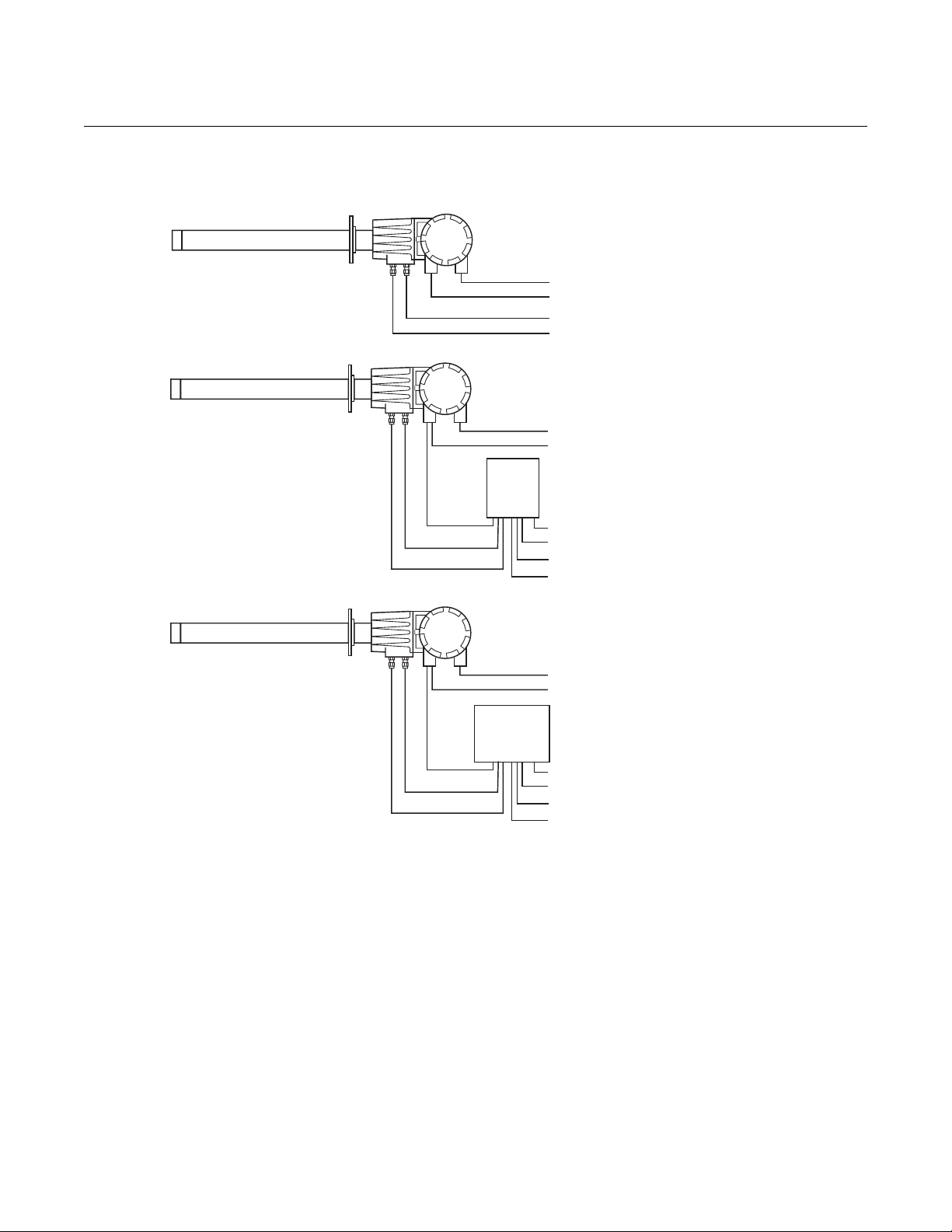
Figure 1. Installation Options Oxymitter 5000 with Integral
Electronics
OXYMITTER 5000
Line Voltage
Fieldbus Digital Signal
Cal. Gas
Instr. Air (Ref. Air)
OXYMITTER 5000 WITH
SPS 4001B
Line Voltage
Fieldbus Digital Signal
SPS
4001B
Instruction Manual
IM-106-350, Rev 2.3
October 2008
LOGIC I/O
Cal. Gas
Ref. Air
LOGIC I/O
Cal. Gas
Ref. Air
Line Voltage
Cal. Gas 1
Cal. Gas 2
Instr. Air (Ref. Air)
OXYMITTER 5000 WITH REMOTE
IMPS 4000 OPTION
Line Voltage
Fieldbus Digital Signal
IMPS
4000
Line Voltage
Cal. Gas 1
Cal. Gas 2
Instr. Air (Ref. Air)
38730054
i-vi
Page 17
Instruction Manual
IM-106-350, Rev 2.3
October 2008
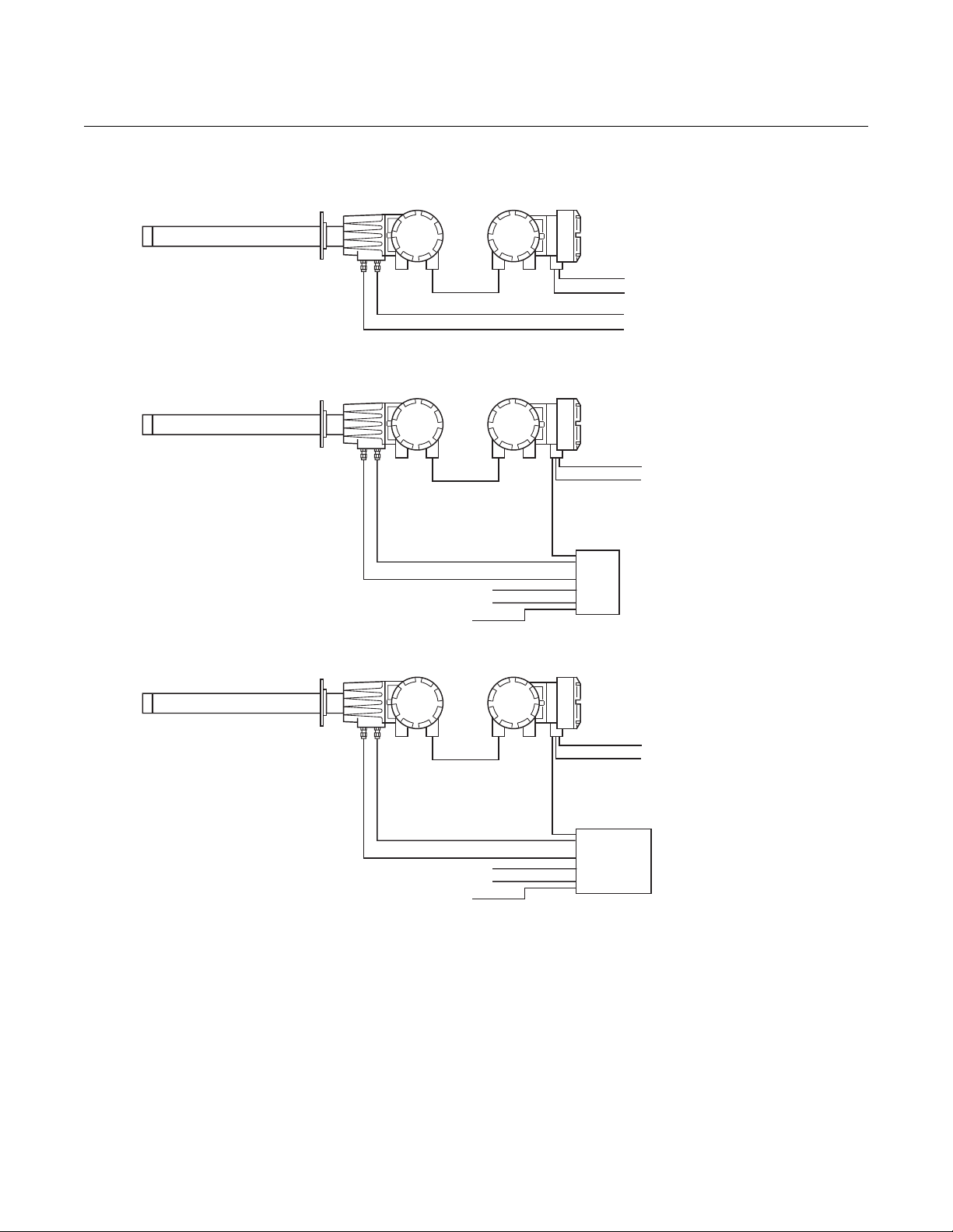
Figure 2. Installation Options Oxymitter 5000 with Remote
Electronics
Oxymitter 5000
OXYMITTER 5000
Line Voltage
Fieldbus Digital Signal
Cal. Gas
Instr. Air (Ref. Air)
Calibration Gas
Reference Air
Cal. Gas 2
Cal. Gas 1
Instr. Air
Calibration Gas
Reference Air
Cal. Gas 2
Cal. Gas 1
Instr. Air
Logic I/O
SPS
4001B
Logic I/O
OXYMITTER 5000
WITH
REMOTE ELECTRONICS
AND SPS 4001B
Line Voltage
Fieldbus Digital Signal
OXYMITTER 5000
WITH
REMOTE ELECTRONICS
AND IMPS
Line Voltage
Fieldbus Digital Signal
IMPS
4000
38730102
i-vii
Page 18

Oxymitter 5000
Instruction Manual
IM-106-350, Rev 2.3
October 2008
QUICK START GUIDE FOR OXYMITTER 5000 SYSTEMS
Before using the Quick Start Guide, please read "WHAT YOU NEED TO
KNOW" on page v of this section.
1. Install the Oxymitter 5000 in an appropriate location on the stack or
duct. Refer to "Selecting Location" in Section 2, Installation, for
information on selecting a location for the Oxymitter 5000.
2. If using an SPS 4001B, connect the calibration gasses to the
appropriate fittings on the SPS 4001B manifold.
3. Connect reference air to the Oxymitter 5000 or SPS 4001B, as
applicable.
4. If using an SPS 4001B, make the wiring connections as shown in the
SPS 4001B Single Probe Autocalibration Sequencer Instruction
Manual.
5. If NOT using an SPS 4001B, make the following wire connections as
shown in Figure 3: line voltage, fieldbus digital signal, and logic I/O.
6. Verify the Oxymitter 5000 switch configuration is as desired. Refer to
"Oxymitter 5000 Configuration", in Section 3, Configuration of Oxymitter
5000 with Membrane Keypad, or "Oxymitter 5000 Configuration", in
Section 4, Configuration of Oxymitter 5000 with LOI.
7. Apply power to the Oxymitter 5000; the cell heater will turn on. Allow
approximately one half hour for the cell to heat to operating
temperature. Once the ramp cycle has completed and the
Oxymitter 5000 is at normal operation, proceed with step 8 or 9.
8. If using an SPS 4001B, initiate a semi-automatic calibration.
9. If NOT using an SPS 4001B, perform a manual calibration. Refer to
"Calibration with Keypad" or "Calibration with LOI" both in Section 10,
Maintenance and Service, in this instruction manual.
NOTE
If your system has a membrane keypad you can refer to the Quick Reference
Guide Instructions on the following page.
i-viii
Page 19
Instruction Manual
IM-106-350, Rev 2.3
October 2008
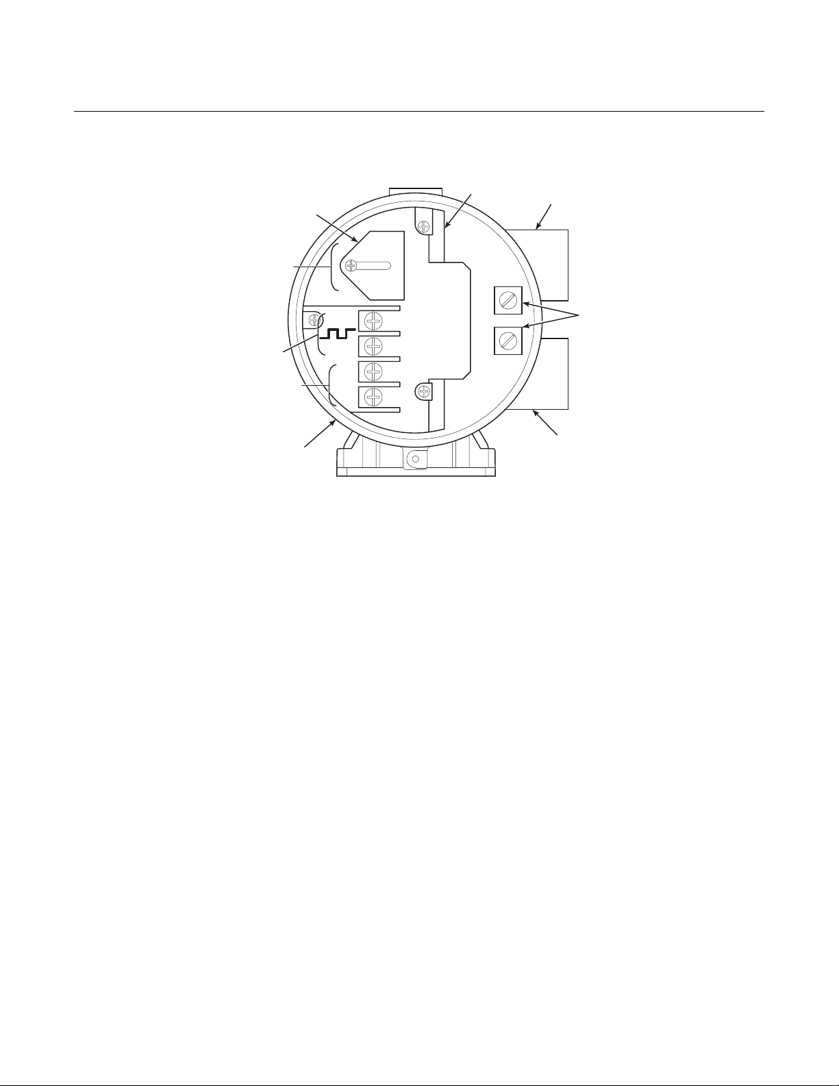
Figure 3. Oxymitter 5000 without
SPS 4001B Wiring Diagram
AC Terminal
Cover
Terminal
Block
Oxymitter 5000
AC Line
VoltagePort
(85 to 264 VAC)
Fieldbus Digital
QUICK REFERENCE GUIDE MANUAL CALIBRATION INSTRUCTIONS
Line Voltage
Logic I/O
Signal
Left Side of
Oxymitter 5000
AC L1
AC N
+
-
+
–
Ground
Lugs
Signal
Port
38730037
Performing a Manual Calibration with a Membrane Keypad
1. Place the control loop in manual.
2. Press the CAL key. The CAL LED will light solid.
3. Apply the first calibration gas.
4. Press the CAL key. When the unit has taken the readings using the first
calibration gas, the CAL LED will flash continuously.
5. Remove the first calibration gas and apply the second calibration gas.
6. Push the CAL key. The CAL LED will light solid. When the unit has
taken the readings using the second calibration gas, the CAL LED will
flash a two-pattern flash or a three-pattern flash. A two-pattern flash
equals a valid calibration, three-pattern flash equals an invalid
calibration.
7. Remove the second calibration gas and cap off the calibration gas port.
8. Press the CAL key. The CAL LED will be lit solid as the unit purges.
When the purge is complete, the CAL LED will turn off.
9. If the calibration was valid, the DIAGNOSTIC ALARMS LEDs indicate
normal operation. If the new calibration values are not within the
parameters, the DIAGNOSTIC ALARMS LEDs will indicate an alarm.
10. Place the control loop in automatic.
i-ix
Page 20

Oxymitter 5000
Instruction Manual
IM-106-350, Rev 2.3
October 2008
Technical Support Hotline:
For assistance with technical problems, please call the Customer Support
Center (CSC). The CSC is staffed 24 hours a day, 7 days a week.
Phone: 1-800-433-6076 1-440-914-1261
In addition to the CSC, you may also contact Field W atch. Field Watch
coordinates Emerson Process Management’s field service throughout the
U.S. and abroad.
Phone: 1-800-654-RSMT (1-800-654-7768)
Emerson Process Management may also be reach ed via th e In ternet thr ough
e-mail and the World Wide Web:
e-mail: GAS.CSC@emerson.com
World Wide Web: www.raihome.com
i-x
Page 21

Instruction Manual
IM-106-350, Rev 2.3
October 2008
Oxymitter 5000
Section 1 Description and Specifications
Component Checklist . . . . . . . . . . . . . . . . . . . . . . . . . . . . . page 1-1
System Overview . . . . . . . . . . . . . . . . . . . . . . . . . . . . . . . . page 1-1
IMPS 4000 (Optional) . . . . . . . . . . . . . . . . . . . . . . . . . . . . . page 1-11
SPS 4001B (Optional) . . . . . . . . . . . . . . . . . . . . . . . . . . . . . page 1-11
Probe Options . . . . . . . . . . . . . . . . . . . . . . . . . . . . . . . . . . . page 1-12
Specifications . . . . . . . . . . . . . . . . . . . . . . . . . . . . . . . . . . .page 1-15
COMPONENT CHECKLIST
A typical Rosemount Analytical Oxymitter 5000 Oxygen Transmitter should
contain the items shown in Figure 1- 1. Record the p art number, serial number,
and order number for each component of your system in the t able located on
the first page of this manual.
Also, use the product matrix in Table 1-1 at the end of this section to comp are
your order number against your unit. The first part of the matrix defines the
model. The last part defines the various options and features of the Oxymitter
5000. Ensure the features and op tions specified by your order n umber ar e on
or included with the unit.
SYSTEM OVERVIEW
Scope This Instruction Manual is designed to supply details needed to install, start
up, operate, and maintain the Oxymitter 5000. Integral signal conditioning
electronics outputs a digital FOUNDATION fieldbus signal representing an O
value and provides a membrane keypad or fully functional Local Operator
Interface (optional) for setup, calibration, and diagnostics. This same
information, plus additional details, can be accessed via fieldbus digital
communications.
2
http://www.raihome.com
Page 22
Oxymitter 5000
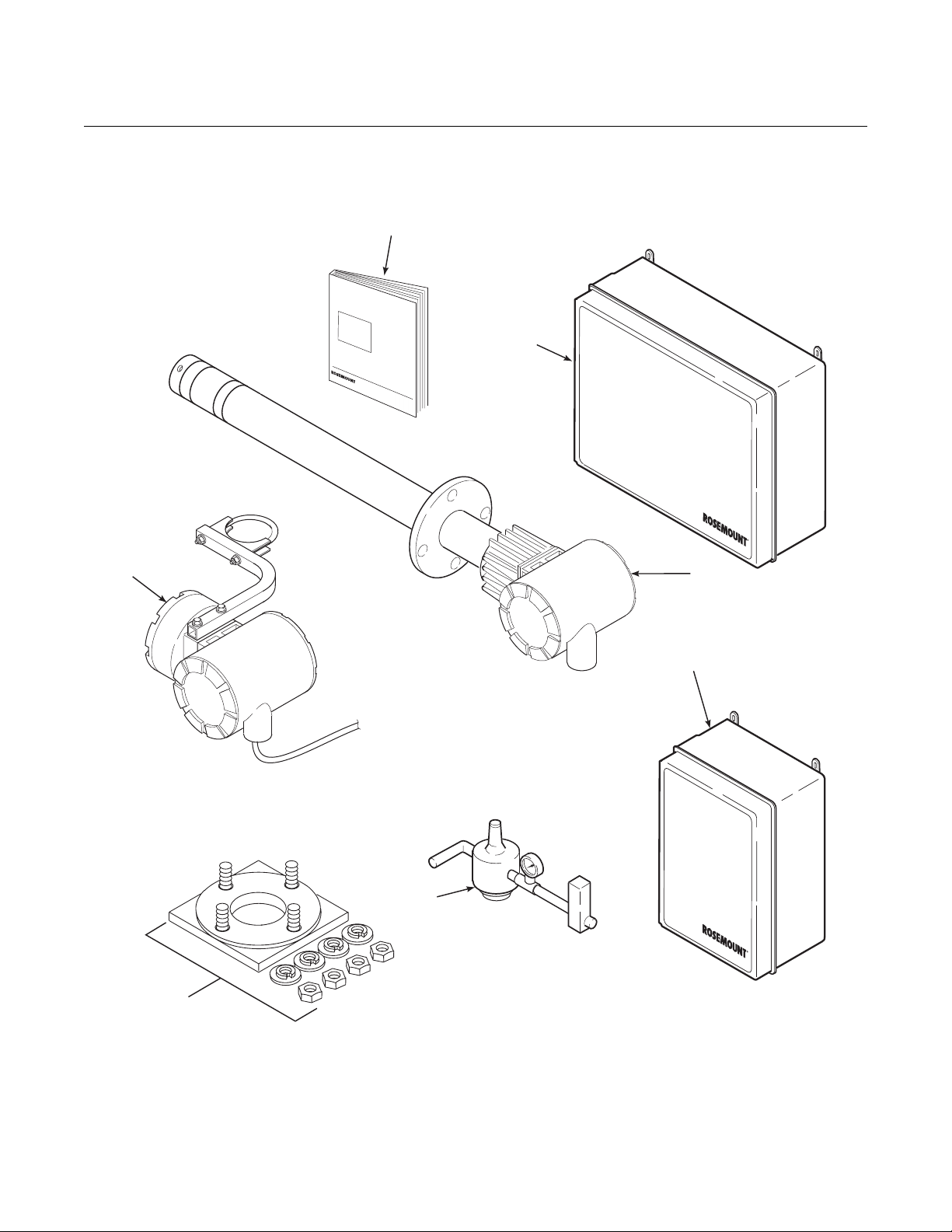
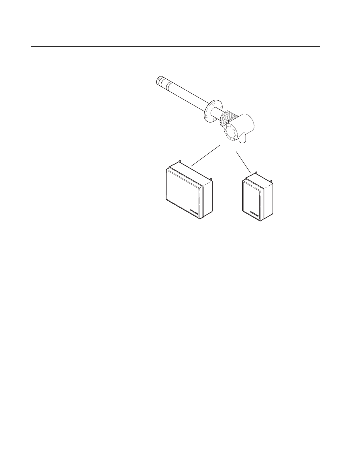
Figure 1-1. Typical System
Package
Instructio
IM-106-340CRev
nManual
December2005
OXYMITTER4000
HAZARDOUS
OXYGEN
A
n
al
.4.2
TRANSMITTER
y
t
Instruction Manual
IM-106-350, Rev 2.3
October 2008
1
AREA
2
i
c
al
Analytical
7
3
4
5
Analytical
6
1. Instruction Manual
2. IMPS 4000 Intelligent Multiprobe Test Gas Sequencer (Optional)
3. Oxymitte r 5000 with Integral Electronics
4. SPS 4001B Single Probe Autocalibration Sequencer (Optional) (Shown with reference air option)
5. Reference Air Set (used if SPS 4001B without reference air option or IMPS 4000 supplied)
6. Adapter Plate with Mounting Hardware and Gasket
7. Remote Electronics and Cable (Optional)
1-2
38730055
Page 23

Instruction Manual
IM-106-350, Rev 2.3
October 2008
Oxymitter 5000
FOUNDATION Fieldbus Technology
FOUNDA TION fieldbus is an all digit al, serial, two-way communication system
that interconnects field equipment such as sensor s, ac tu at or s, an d
controllers. Fieldbus is a Local Area Network (LAN) for instru ments used in
both process and manufacturing automation with built-in capacity to distribute
the control application across the network. The fieldbus environment is the
base level group of digital networks in the hierarchy of planet networks.
The fieldbus includes a standardized physical interface to the wire, bus
powered devices on a single wire, and intrinsic safety options, and enables
additional capabilities, such as:
• Increased capabilities due to full digital communications
• Reduced wiring and wire terminations due to multiple devices on one
set of wires
• Increased selection of suppliers due to interoperability
• Reduced loading on control room equipment with the distribution of
some control and input/output functions to field devices
• Speed options for process control and manufacturing applications
System Description The Oxymitter 5000 is designed to measure the net concentration of oxygen
in an industrial combustion processes process; i.e., the oxygen remaining
after all fuels have been oxidized. The pro be is permanently po sitioned within
an exhaust duct or stack and performs its task without the use of a sampling
system.
The equipment measures oxygen percentage by reading the voltage
developed across a heated electrochemical cell, which consists of a small
yttria stabilized, zirconia disc. Both sides of the disc are coated with porous
metal electrodes. When operated at the proper temperature, the millivolt
output voltage of the cell is given by the following Nernst equation:
EMF = KT log10(P1/P2) + C
Where:
1. P2 is the partial pressure of the oxygen in the measured gas on one
side of the cell.
2. P1 is the partial pressure of the oxygen in the reference air on the
opposite side of the cell.
3. T is the absolute temperature.
4. C is the cell constant.
5. K is an arithmetic constant.
NOTE
For best results, use clean, dry, instrument air (20.95% oxygen) as the
reference air.
1-3
Page 24

Instruction Manual
IM-106-350, Rev 2.3
Oxymitter 5000
When the cell is at operating temperature and there are unequal oxygen
concentrations across the cell, oxygen ions will travel from the high oxygen
partial pressure side to the low oxygen partial pressure side of the cell. The
resulting logarithmic output voltage is approximately 50 mV per decade. The
output is proportional to the inverse logarithm of the oxygen concentration.
Therefore, the output signal increases as the oxygen concentration of the
sample gas decreases. This characteristic enables the Oxymitter 5000 to
provide exceptional sensitivity at low oxygen concentrations.
The Oxymitter 5000 measures net oxygen concentration in the presence of all
the products of combustion, including water vapor. Therefore, it may be
considered an analysis on a "wet" basis. In comparison with older metho ds,
such as the portable apparatus, which provides an analysis on a "dry" gas
basis, the "wet" analysis will, in general, indicate a lower percentage of
oxygen. The difference will be proportional to the water content of the
sampled gas stream.
October 2008
System Configuration Oxymitter 5000 units are available in seven length options, giving the user the
flexibility to use an in situ penetration appropriate to the size of the stack or
duct. The options on length are 18 in. (457 mm), 3 ft (0,91 m), 6 ft (1,83 m),
9 ft (2,7 m), 12 ft (3,66 m), 15 ft (4,57 m), and 18 ft (5,49 m).
The integral electronics control probe temperature and provide an output that
represents the measured oxyg en concentration. The power sup ply can accept
voltages of 90-250VAC and 50/60 Hz; therefore no setup procedures are
required. The oxygen sensing cell is maintained at a constant temperature by
modulating the duty cycle of the probe heater portion of the integral electronics. The integral electronics accepts millivolt signals generated by the sensing
cell and produces the outputs to be used by remotely connected devices. The
output is a FOUNDATION fieldbus digital communication signal.
The Oxymitter 5000 transmitter is available with an integral or remote electronics package. T wo calibration gas sequencers are available: the IMPS
4000 and the SPS 4001B (Figure 1-2).
Systems with multiprobe applications may employ an optional IMPS 4000
Intelligent Multiprobe Test Gas Sequencer. The IMPS 4000 provides automatic calibration gas sequencing for up to four Oxymitter 5000 unit s and
accommodates autocalibrations based on the CALIBRATION RECOMMENDED signal from the Oxymitter 5000, a timed interval set up via fieldbus
or the IMPS 4000, or when a calibration request is initiated.
For systems with one or two Oxymitter 5000 unit s per combustion process, an
optional SPS 4001B Single Probe Autocalibration Sequencer can be used
with each Oxymitter 5000 to provide automatic calibration gas sequencing.
The SPS 4001B is fully enclosed in a NEMA cabinet suited for wall-mounting.
The sequencer performs autocalibrations based on the CALIBRATION RECOMMENDED signal from the Oxymitter 5000, a timed interval set up in fieldbus, or whenever a calibration request is initiated.
1-4
Page 25
Instruction Manual
Analytical
IM-106-350, Rev 2.3
October 2008
Figure 1-2. Oxymitter 5000
AutoCalibration System Options
Oxymitter 5000
OXYMITTER 5000
Analytical
IMPS 4000
(1 to 4 Probes)
Analytical
SPS 4001B
(1 Probe)
38730092
System Features 1. The CALIBRATION RECOMMENDED feature detects wh en the sensing
cell is likely out of limits. This may eliminate the need to calibrate on a
"time since last cal" basis.
2. The cell output voltage and sensitivity increase as the oxygen
concentration decreases.
1-5
Page 26
Oxymitter 5000
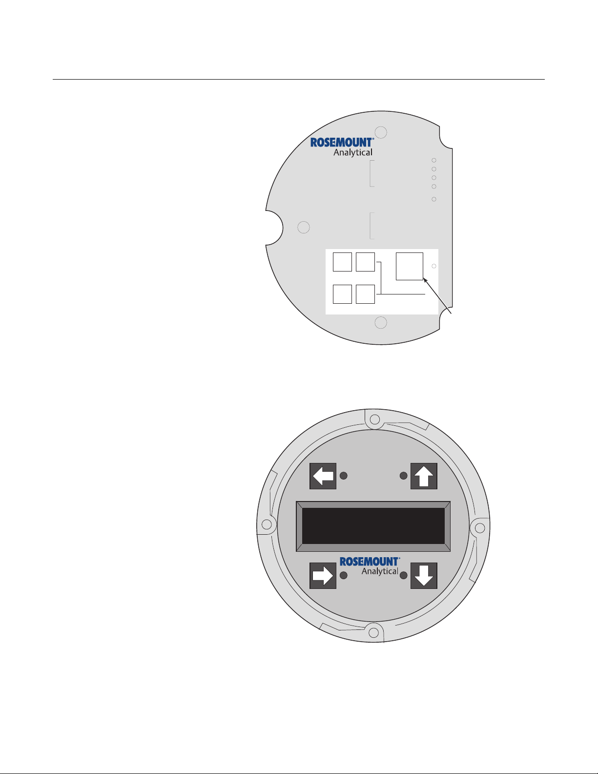
Figure 1-3. Membrane Keypad
HEATERT/C
DIAGNOSTIC
ALARMS
CALIBRATIONRECOMMENDED
TEST
POINTS
HEATER
02 CELL
CALIBRATION
02 CELL mV +
02 CELL mv HEATERT/C +
HEATERT/C -
Instruction Manual
IM-106-350, Rev 2.3
October 2008
Figure 1-4. Local Operator
Interface (LOI)
INC INC
HIGH
LOW
GAS
GAS
DEC DEC
CAL
TEST GAS +
PROCESS -
%02
MEMBRANE
KEYPAD
3. Membrane keypad, Figure 1-3, and FOUNDATION fieldbus
communication are standard.
38730056
1-6
38730057
4. An optional Local Operator Interface, Figure 1-4, allows continuous O
2
display and full interface capability.
5. Field replaceable cell, heater, thermocouple, and diffusion element.
6. The Oxymitter 5000 is constructed of rugged 316 L stain less steel for all
wetted parts.
Page 27

Instruction Manual
IM-106-350, Rev 2.3
October 2008
Oxymitter 5000
7. The electronics are adaptable for line voltages from 90-250 VAC;
therefore, no configuration is necessary.
8. The Oxymitter 5000 membrane keypad is available in five languages:
English
French
German
Italian
Spanish
9. An operator can calibrate and diagnostically troubleshoot the Oxymitter
5000 in one of four ways:
a. Membrane Keypad. The membrane keypad, housed within the right
side of the electronics housing, provides fault indication by way of
flashing LEDs. Calibration can be performed from the membrane
keypad.
b. LOI. The optional LOI takes the place of the membrane keypad and
allows local communication with the electronics. Refer to Section 6
for more information.
c. FOUNDATION fieldbus Interface. The Oxymitter 5000's output
carries a signal containing the oxygen le vel encoded in digit al format.
This digital output can also be used to communicate with the
Oxymitter and access all of the Oxymitter’s status information.
d. Optional IMPS 4000. The Programmable Logic Controller (PLC) in
the IMPS 4000 provides fault indications using flashing LEDs and
LCD display messages. Refer to the IMPS 4000 Intelligent
Multiprobe Test Gas Sequencer Instruction Manual for more
information.
Handling the Oxymitter 5000
It is important that printed circuit boards and integrated circuits are handled only when
adequate antistatic precautions have been taken to prevent possible equipment damage.
The Oxymitter 5000 is designed for industrial applications. Treat each component of the
system with care to avoid physical damage. Some probe components are made from
ceramics, which are susceptible to shock when mishandled.
System Considerations Prior to installing your Oxymitter 5000, make sure you have all the
components necessary to make the system installation. Ensure all the
components are properly integrated to make the system functional.
After verifying that you have all the component s, select mounting locations
and determine how each component will be placed in terms of available line
voltage, ambient temperatures, environmental considerations, convenience,
and serviceability.
Figure 1-5 shows a typical system wiring.
A typical system installation for an Oxymitter 5000 with integral electronics is
shown in Figure 1-6. A typical system installation for an Oxymitter 5000 with
remote electronics is shown in Figure 1-7.
1-7
Page 28
Oxymitter 5000
Instruction Manual
IM-106-350, Rev 2.3
October 2008
A source of instrument air is optional at the Oxymitter 5000 for reference
air use. Since the unit is equipped with an in place calibration feature,
provisions can be made to permanently connect calibration gas bottles to the
Oxymitter 5000.
If the calibration gas bottles will be permanently connected, a check valve is
required next to the calibration fittings on the integral electronics.
This check valve is to prevent breathing of the calibration gas line and
subsequent flue gas condensation and corrosion. The check valve is in
addition to the stop valve in the calibration gas kit or the solenoid valves in the
IMPS 4000 or SPS 4001B.
NOTE:
The electronics is rated NEMA 4X (IP66) and is capable of operation at
temperatures up to 185°F (85°C).
The optional LOI is also rated for operation at temperatures up to 185°F
(85°C). The infrared keypad functionality will degrade at temperatures above
158°F (70°C).
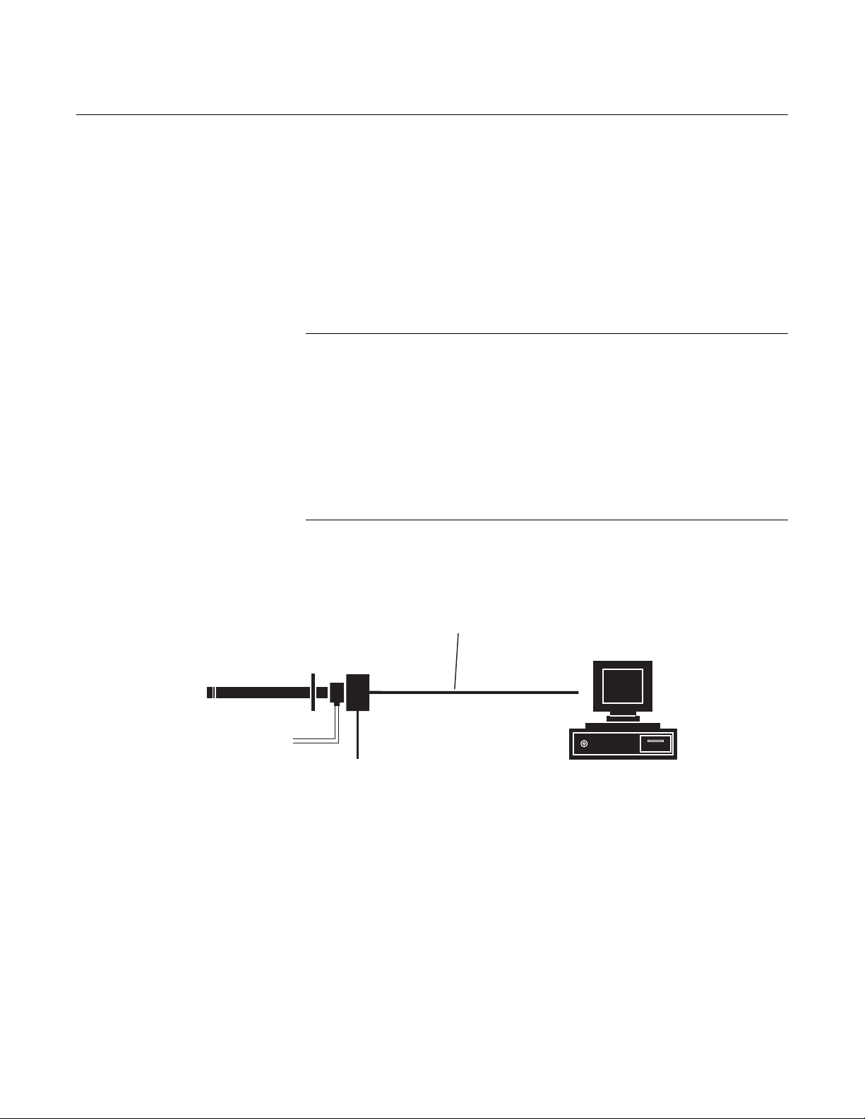
Figure 1-5. Oxymitter 5000
FOUNDATION Fieldbus
Connections
with Integral Electronics
2 Calibration Gas Lines
by Customer
[ ( ) max]300 ft 90 m
Retain the packaging in which the Oxymitter 5000 arrived from the factory in
case any components are to be shipped to another site. This packaging has
been designed to protect the product.
Oxymitter 5000
Line Voltage
Fieldbus Digital
Signal
Fieldbus Computer
Terminal
38730058
1-8
Page 29
Instruction Manual
IM-106-350, Rev 2.3
October 2008
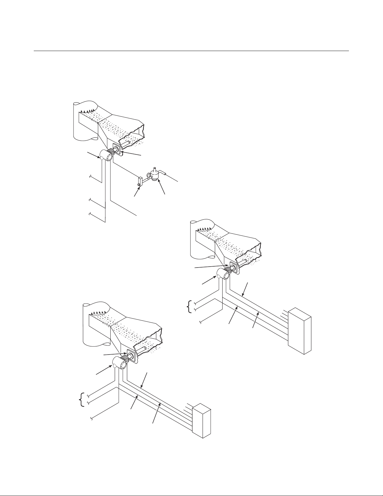
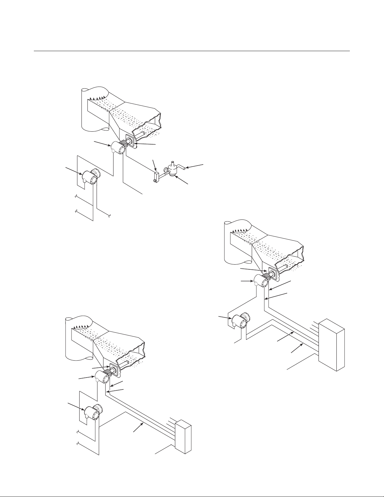
Figure 1-6. Typical System
Installation - Oxymitter 5000 with
Integral Electronics
Oxymitter 5000
Gases
Stack
Oxymitter
5000
Line
Voltage
Logic I/O
Fieldbus Digital
Signal
STANDARD
Duct
Adapter
Plate
Flowmeter
Calibration
Gas
SPS 4001B* SINGLE PROBE
AUTOCALIBRATION OPTION
(WITH REFERENCE AIR OPTION)
Gases
Pressure
Regulator
Voltage
Instrument
Air Supply
(Reference Air)
Gases
Stack
Adapter
Plate
Oxymitter
5000
Line
IMPS 4000* MULTIPROBE
AUTOCALIBRATION
OPTION
Duct
Calibration
Gas
Inst. Air Supply
Calibration Gas 2
Calibration Gas 1
Adapter Plate
Line Voltage
Fieldbus
Digital Signal
Oxymitter
5000
Stack
Calibration Gas
Logic I/O
Duct
Calibration Gas 2
Calibration Gas 1
Reference
Air
Fieldbus
Digital Signal
Inst. Air Supply
SPS 4001B
Logic I/O
*Note: The IMPS 4000 or SPS 4001B must
Reference
Air
IMPS 4000
be installed in a non-hazardous,
explosive-free environment.
38730100
1-9
Page 30
Oxymitter 5000
Figure 1-7. Typical System
Installation - Oxymitter 5000 with
Remote Electronics
Instruction Manual
IM-106-350, Rev 2.3
October 2008
Oxymitter 5000
Remote
Electronics
Logic I/O
Fieldbus Digital
Signal
Gases
Stack
Line
Voltage
STANDARD
Duct
Adapter Plate
Flowmeter
Calibration
Gas
Instrument
Air Supply
(Reference Air)
Pressure
Regulator
Adapter Plate
Gases
Stack
IMPS 4000* MULTIPROBE
AUTOCALIBRATION
OPTION
Duct
SPS 4001B* SINGLE PROBE
AUTOCALIBRATION OPTION
(WITH REFERENCE AIR OPTION)
Gases
Duct
Stack
Adapter Plate
Oxymitter
5000
Remote
Electronics
Line Voltage
Fieldbus Digital
Signal
Calibration Gas
Reference Air
Calibration Gas 1
Logic I/O
Line Voltage
Inst. Air Supply
Calibration Gas 2
Electronics
SPS 4001B
Oxymitter 5000
Remote
Line Voltage
Calibration Gas
Reference Air
Inst. Air Supply
Calibration Gas 2
Calibration Gas 1
Logic I/O
Fieldbus Digital
Signal
Line Voltage
IMPS 4000
*Note: The IMPS 4000 or SPS 4001B must
be installed in a non-hazardous,
explosive-free environment.
38730059
1-10
Page 31

Instruction Manual
IM-106-350, Rev 2.3
October 2008
Oxymitter 5000
IMPS 4000 (OPTIONAL) Information on the IMPS 4000 is available in the IMPS 4000 Intelligent
Multiprobe Test Gas Sequencer Instruction Manual.
SPS 4001B (OPTIONAL) The SPS 4001B Single Probe Autocalibration Sequencer provides the
capability of performing automatic, timed or on demand, calibrations of a
single Oxymitter 5000 without sending a technician to the installation site.
Mounting The SPS 4001B is fully enclosed in a NEMA cabinet suited for wall-mounting.
This cabinet provides added protection against dust and minor impacts. The
SPS 4001B consists of a manifold and a calibration gas flowmeter. The manifold provides electrical feedthroughs and calibration gas ports to route power
and signal connections and calibration gases to and from the sequencer. In
addition, the manifold houses two calibration gas solenoids that sequence the
gases to the Oxymitter 5000, a pressure switch that detects low calibration
gas pressure, and two PC boards. A terminal strip housed within the terminal
cover provides convenient access for all user connections.
Components optional to the SPS 4001B include a reference air flowmeter and
pressure regulator. The reference air flowmeter indicates the flow rate of
reference air continuously flowing to the Oxymitter 5000. The reference air
pressure regulator ensures the instrument air (reference air) flowing to the
Oxymitter 5000 is at a constant pressure [20 psi (138 kPa)]. The regulator
also has a filter to remove particulates in the refer ence air and a drain va lve to
bleed the moisture that collects in the filter bowl.
Brass fittings and Teflon tubing are standard. Stainless steel fittings and
tubing are optional. Also, disposable calibration gas bottles are available as
an option or can be purchased through a local supplier.
Operation The SPS 4001B works in conjunction with the Oxymitter 5000's CALIBRA-
TION RECOMMENDED feature to perform an autocalibration. This feature
automatically performs a gasless calibration check every hour on the Oxymitter 5000. If a calibration is recommended and its contact output signal is set
for "handshaking" with the sequencer, the Oxymitter 5000 sends a signal to
the sequencer. The sequencer automatically performs a calibration upon
receiving the signal. Thus, no human interface is required for the automatic
calibration to take place.
For further SPS 4001B information, refer to the SPS 4001B Single Probe
Autocalibration Sequencer Instruction Manual.
1-11
Page 32

Oxymitter 5000
PROBE OPTIONS
Diffusion Elements Ceramic Diffusion Assembly
The ceramic diffusion assembly, Figure 1-8, is the traditional design for the
probe. Used for over 25 years, the ceramic diffusion assembly provides a
greater filter surface area. This element is also available with a flame arrestor,
and with a dust seal for use with an abrasive shield.
Figure 1-8. Ceramic Diffusion
Assembly
Instruction Manual
IM-106-350, Rev 2.3
October 2008
Figure 1-9. Snubber Diffusion
Assembly
38730002
Snubber Diffusion Assembly
The snubber diffusion assembly, Figure 1-9, is satisfactory for most
applications. This element is also available with a flame arrestor and with a
dust seal for use with an abrasive shield.
38730048
1-12
Page 33

Instruction Manual
IM-106-350, Rev 2.3
October 2008
Figure 1- 10. Hastelloy Cup-T ype
Diffusion Assembly
Oxymitter 5000
Cup-Type Diffusion Assembly
The cup-type diffusion assembly, Figure 1-10, is typically used in high
temperature applications where frequent diffusion element plugging is a
problem. It is available with either a 10 or 40 micron, sintered, Hastelloy
element.
This element is also available with a dust seal for use with an abrasive shield.
Abrasive Shield Assembly
38730047
The abrasive shield assembly, Figure 1-11, is a stainless steel tube that
surrounds the probe assembly. The shield protects against particle abrasion,
provides a guide for ease of insertion, and acts as a position support,
especially for longer probes. The abrasive shield assembly uses a modified
diffuser and vee deflector assembly, fitted with dual dust seal packing.
1-13
Page 34

Oxymitter 5000
Figure 1-11. Abrasive Shield
Assembly
Instruction Manual
IM-106-350, Rev 2.3
October 2008
1-14
NOTE
In highly abrasive applications, rotate the shield 90 degrees at normal
service intervals to present a new wear surface to the abrasive flow stream.
Page 35

Instruction Manual
IM-106-350, Rev 2.3
October 2008
SPECIFICATIONS
Oxymitter 5000
Oxymitter Specifications
Range
O
2
Accuracy ±0.75% of reading or 0.05% O2, whichever is greater
System Response to Calibration
Gas
Temperature Limits
Process 32° to 1300°F (0° to 704°C) up to 2400°F (1300°C)
Electronics Housing -40° to 158°F (-40° to 70°C) ambient
Electronics Package -40° to 185°F (-40° to 85°C) [Operating temperature
Local Operator Interface -40° to 158°F (-40° to 70°C), [above 158°F (70°C) the
Probe Lengths 18 in. (457 mm) 12 ft (3,66 m)
Mounting and Mounting Position Vertical or horizontal;
Materials
Probe Wetted or welded parts - 316L stainless steel (SS)
Electronics Enclosure Low-copper aluminum
Calibration Manual, semi-automatic, or automatic
Calibration Gas Mixtures
Recommended
Calibration Gas Flow 2.5 l/min (5 scfh)
Reference Air 1 l/min (2 scfh), clean, dry, instrument-quality air
Electronics NEMA 4X, IP66 with fitting and pipe on reference
Electric Noise EN 61326-1, Class A
Line Voltage 90-250 VAC, 48/62 Hz. No configuration necessary.
Certifications General Purpose
Initial – less than 3 seconds, T90 – less than 8
seconds
with optional accessories
of electronics inside of instrument housing, as read by
OUNDATION fieldbus.]
F
infrared keypad will cease to function, but the
Oxymitter 5000 will continue to operate properly.]
3 ft (0,91 m) 15 ft (4,57 m)
6 ft (1,83 m) 18 ft (5,49 m)
9 ft (2,74 m)
a spool piece, (P/N 3D39761G02), is available to
offset transmitter housing from hot ductwork.
Non-wetted parts - 304 SS, low-copper aluminum
0.4% O
8% O2, Balance N
(20.95% O
exhaust port to clear dry atmosphere
3/4 in. -14 NPT conduit port
, Balance N
2
), regulated to 34 kPa (5 psi)
2
2
2
C
US
Table continued on next page
APPROVED
1-15
Page 36

Oxymitter 5000
Instruction Manual
IM-106-350, Rev 2.3
October 2008
Oxymitter Specifications
Signals
Digital Output FOUNDATION fieldbus compatible
Logic I/O Two-terminal logic contact configurable as either an
alarm output or as a bi-directional calibration
handshake signal to IMPS 4000 or SPS 4001B,
self-powered (+5 V) in series with 340 ohms
Conduit ports — 3/4 in.-14 NPT (for Foundation
fieldbus and logic I/O signal lines)
Power Requirements:
Probe Heater 175 W nominal
Electronics 10 W nominal
Maximum 500 W
1-16
Page 37

Instruction Manual
IM-106-350, Rev 2.3
October 2008
Table 1-1. Product Matrix
OXT5A Oxymitter 5000 In Situ Oxygen Transmitter with FOUNDATION Fieldbus Communications
Oxygen Transmitter - Instruction Book
Code Sensing Probe Type
1 ANSI (N. American Std.) Probe with Ceramic Diffuser
2 ANSI Probe with Flame Arrestor and Ceramic Diffuser (General Purpose Only)
3 ANSI Probe with Snubber Diffuser
4 DIN (European Std.) Probe with Ceramic Diffuser
5 DIN Probe with Flame Arrestor and Snubber Diffuser (General Purpose Only)
6 DIN Probe with Snubber Diffuser
Code Probe Assembly
0 18 in. (457 mm) Probe
1 18 in. (457 mm) Probe with Abrasive Shield
2 3 ft (0,91 m) Probe
3 3 ft (0,91 m) Probe with Abrasive Shield
4 6 ft (1,83 m) Probe
5 6 ft (1,83 m) Probe with Abrasive Shield
6 9 ft (2,74 m) Probe
7 9 ft (2,74 m) Probe with Abrasive Shield
8 12 ft (3,66 m) Probe
9 12 ft (3,66 m) Probe with Abrasive Shield
A 15 ft (4,57 m) Probe with Abrasive Shield
B 18 ft (5,49 m) Probe with Abrasive Shield
Code Mounting Hardware- Stack Side
0 No Adapter Plate
1 New Installation - Square Weld Plate with Studs
2 Mounting to Model 218 Mounting Plate (with Model 218 Shield Removed)
3 Mounting to Existing Model 218 Support Shield
4 Competitor’s Mount
5 Mounting to Model 132 Adapter Plate
Code Mounting Hardware- Probe Side
0 No Mounting Hardware in Adapter Plate
1 Probe Only (ANSI) (N. American Std.)
2 New Bypass or New Abrasive Shield (ANSI)
4 Probe Only (DIN)
5 New Bypass or New Abrasive Shield (DIN)
Code Electronic Housing - NEMA 4X, IP66
OXT5A331112 Example
(2)
12 Transient Protected Filtered Termination, Integrally Mounted to Probe.
14 Transient Protected Filtered Termination, Mounted Remotely, Requires Cable.
(1)
(1)
(1)
(1)
(1)
(1)
(1)
Oxymitter 5000
1-17
Page 38

Oxymitter 5000
Cont’d
Code Operator Interface
1 Membrane Keypad - Fieldbus, Blind Cover
2 Membrane Keypad - Fieldbus, Window Cover
3 Gas Fluorescent LOI, Fieldbus, English only, Window Cover
Code Language
1English
2German
3French
4 Spanish
5Italian
Cont’d 1 3 00 01 00 00 Example
(3)
Code Termination Filtering
00 No Option - Specified as Part of Electronic Housing
Code Calibration Accessories
00 No Hardware
01 Calibration Gas Flow Rotometers & Reference Gas Set
02 Autocalibration Systems - Order by separate part number (for safe areas only)
Code Control Suite Functionality
00 Basic Control Suite
01 Deduct Basic Control Suite
Code Electronics to Probe Cable
00 No Cable
10 20 ft (6 m) Cable
11 40 ft (12 m) Cable
12 60 ft (18 m) Cable
13 80 ft (24 m) Cable
14 100 ft (30 m) Cable
15 150 ft (45 m) Cable
16 200 ft (61 m) Cable
Instruction Manual
IM-106-350, Rev 2.3
October 2008
NOTES:
High Sulfur Service:
High sulfur cell can be selected for any probe; add a line item note to your purchase order requesting the high sulfu r ZrO2 cell in place of the standard ZrO2
cell. Add 4232 UOM to the system matrix UOM total.
(1)
Recommended uses: High velocity particulates in flue stream, installation within 10 ft (3,5 m) of soot blowers or heavy salt cake buildup.
Applications: Pulverized coal, recovery boilers, lime kiln.
(2)
Where possible, specify ANSI or DIN designation; otherwise, provide details of the existing mounting plate as follows:
Plate with studs Bolt circle diameter, number, and arrangement of studs; stud thread; and stud height above mounting plate.
Plate without studs Bolt circle diameter, number, and arrangement of holes; thread; and depth of stud mounting plate with accessories.
(3)
Startup, calibration, and operation can be implemented using the standard membrane keypad. Remote access and additional functionality available via
Fieldbus Communications (DeltaV).
1-18
Page 39

Instruction Manual
IM-106-350, Rev 2.3
October 2008
Table 1-2. Calibration
Components
Table 1-3. Intelligent Multiprobe
Test Gas Sequencer Versions
Oxymitter 5000
Part Number Description
1A99119G01 Two disposable calibration gas bottles - 0.4% and 8% O
nitrogen - 550 liters each*
1A99119G02 Two flow regulators for calibration gas bottles
1A99119G03 Bottle rack
Notes:
*Calibration gas bottles cannot be shipped via airfreight.
When the bottles are used with CALIBRA TI ON RECOMMENDED features, the bott les should provide
2 to 3 years of calibrations in normal service.
Part Number Description Number of Oxy mitters
3D39695G01 IMPS 1
3D39695G02 IMPS 2
3D39695G03 IMPS 3
3D39695G04 IMPS 4
3D39695G05 IMPS w/115 V Heater 1
3D39695G06 IMPS w/115 V Heater 2
3D39695G07 IMPS w/115 V Heater 3
3D39695G08 IMPS w/115 V Heater 4
3D39695G09 IMPS w/220V Heater 1
3D39695G10 IMPS w/220V Heater 2
3D39695G11 IMPS w/220V Heater 3
3D39695G12 IMPS w/220V Heater 4
, balance
2
1-19
Page 40

Oxymitter 5000
Instruction Manual
IM-106-350, Rev 2.3
October 2008
1-20
Page 41

Instruction Manual
IM-106-350, Rev 2.3
October 2008
Section 2 Installation
Mechanical Installation . . . . . . . . . . . . . . . . . . . . . . . . . . . page 2-2
Electrical Installation (with Integral Electronics) . . . . . . . page 2-11
Electrical Installation (with Remote Electronics) . . . . . . .page 2-14
Pneumatic Installation . . . . . . . . . . . . . . . . . . . . . . . . . . . . page 2-17
IMPS 4000 Connections . . . . . . . . . . . . . . . . . . . . . . . . . . .page 2-19
SPS 4001B Connections . . . . . . . . . . . . . . . . . . . . . . . . . . page 2-19
Before installing this equipment, read the "Safety Instructions" for the wiring and installation
of this apparatus in Appendix A of this Instruction Manual. Failure to follow safety
instructions could result in serious injury or death.
Oxymitter 5000
Install all protective equipment covers and safety ground leads after installation. Failure to
install covers and ground leads could result in serious injury or death.
The Oxymitter 5000 (OXT5A) can be installed in general purpose areas only. Do not install
the OXT5A in hazardous areas. For hazardous areas use the OXT5C.
http://www.raihome.com
Page 42

Instruction Manual
IM-106-350, Rev 2.3
Oxymitter 5000
October 2008
MECHANICAL INSTALLATION
Selecting Location 1. The location of the Oxymitter 5000 in the stack or flue is most important
for maximum accuracy in the oxygen analyzin g pr oc ess. The Oxymitter
5000 must be positioned so the gas it measures is represen t ative of the
process. Best results are normally obt ained if the Oxymitter 5000 is
positioned near the center of the duct (40-60% insertion). Longer ducts
may require several Oxymitter 5000 units since the O
stratification. A point too near the wall of the duct, or the inside radius of
a bend, may not provide a representative sample because of the very
low flow conditions. The sensing point should be selected so the
process gas temperature falls within a range of 32° to 1300°F
(0° to 704°C). Figure 2-1 through Figure 2-8 provide mechanical
installation references. The ambient temperature of the integral
electronics housing must not exceed 185°F (85°C). For higher ambi ent
temperatures, we recommend the remote mounted electronics option.
2. Check the flue or stack for holes and air leakage. The presence of this
condition will substantially affect the accuracy of the oxygen reading.
Therefore, either make the necessary repairs or install the Oxymitter
5000 upstream of any leakage.
3. Ensure the area is clear of internal and external obstructions that will
interfere with installation and maintenance access to the membrane
keypad or LOI. Allow adequate clearance for removal of the Oxymitter
5000.
can vary due to
2
Do not allow the temperature of the Oxymitter 5000 electronics to exceed 185°F (85°C) or
damage to the unit may result.
Probe Installation 1. Ensure all components are available to install the Oxymitter 5000. If
equipped with the optional ceramic diffusion element, ensure it is not
damaged.
2. The Oxymitter 5000 may be installed in tact as it is received.
NOTE
An abrasive shield is recommended for high velocity particulates in the flue
stream (such as those in coal-fired boilers, kilns, and recovery boilers).
Vertical and horizontal brace clamps are provided for 9 ft and 12 ft (2,75 m
and 3,66 m) probes to provide mechanical support for the Oxymitter 5000.
Refer to Figure 2-6.
3. Weld or bolt adapter plate (Figure2-5) onto the duct.
4. If using the optional ceramic diffusion element, the vee deflector must
be correctly oriented. Before inserting the Oxymitter 5000, check the
direction of gas flow in the duct. Orient the vee deflector so the apex
points upstream toward the flow (Figure 2-7). This may be done by
loosening the setscrews and rotating the vee deflector to the desired
position. Retighten the setscrews.
2-2
Page 43

Instruction Manual
IM-106-350, Rev 2.3
October 2008
Figure 2-1. Oxymitter 5000
Probe Installation
Oxymitter 5000
Dimensions are in
inches with millimeters
in parentheses.
Note:
Insulate if exposed to
Ambient weather conditions
(808)
(406)
18 in.
49.8
(1265)
34
(864)
3ft
85.8
(2179)
70
(1778)
6ft
121.8
(3094)
106
(2692)
9ft
1.55
157.8
142
6.52
(166)
(39)
(4008)
(3607)
12 ft
193.8
(4923)
178
(4521)
15 ft
(73)
2.89
229.8
(5837)
214
(5436)
18 ft
Cover Removal and Access
12
(305)
31.8
REF.
GAS
E
V
I
-
L
A
E
R
T
E
I
H
P
U
S
O
M
T
A
E
V
I
S
O
L
S
O
M
T
A
E
V
I
S
O
L
C
R
-
I
W
-
X
E
E
H
-
W
-
X
E
N
R
SMART FAMILY
RosemountAnalyticalInc.
R
E
R
I
-
TM
HART
800-433-6076
Solon,OH 44139
TM
OXYMITTER 5000
-
N
I
-
SERIAL NO.
C
N
E
H
W
T
H
G
I
T
P
E
E
K
500 VA
5 Amps
4-20 mA
85-264 VAC 48-62 Hz
TAG NO.
VOLTS: WATTS:
OUTPUT: LINE FUSE:
E
V
I
L
A
T
I
U
C
R
I
C
N
E
H
W
T
H
G
I
T
P
E
E
K
3/4 NPT
Elec Conn
Ref Air
Cal Gas
CAL.
GAS
G
N
I
N
R
A
P
P
G
N
I
N
R
A
P
DIM "B"
DIM "A"
Table 2. Installation/Removal
PROBE
DIN 6 mm Tube
ANSI 1/4 (6.35) Tube
Dim "B”
12
16
(305)
12.50 (318)
Removal Envelope
Process flow must be in
this direction with respect
to deflector 3534B48G01
3535B18H02
3535B45H01
0.062 THK Gasket
ANSI
DIN
2.27 (58)
Dia Max
for probe
3.80(96)
Add to Dim “A”
4.77 (121)
Dim "A"
Diffuser
5.14(131)
with Ceramic
6.02 (153)
With
Add to Dim “A”
Snubber
Standard
for probe with
Ceramic Diffuser
Diffuser
Arrestor
and Flame
DIN
4512C19H01
ANSI
Table 1. Mounting Flange
4512C17H01
7.28
(185)
6.00
(153)
Flange
Dia
0.71
0.75
Hole
(18)
(20)
Dia
5.71
4.75
Eq Sp
(4) Holes
Bottom View
(145)
(121)
on BC
38730049
2-3
Page 44

Oxymitter 5000
Figure 2-2. Oxymitter 5000
Remote Electronics Installation
Instruction Manual
IM-106-350, Rev 2.3
October 2008
REMOTE ELECTRONICS
WITH MEMBRANE KEYPAD AND BLIND COVER
2.44
(62,0)
DIA.
2.21
(56,0)
6.48
(164,6)
8.72 (221,5)
3.33
(84,6)
REMOTE ELECTRONICS
WITH LOI AND WINDOW COVER
7.47
(189,8)
5.52
(140,2)
2.62
(66,5)
2.68 (68,1)
PIPE MOUNT
CONFIGURATION
Note:
Dimensions are in inches with millimeters in parentheses.
WALL MOUNT
CONFIGURATION
38730099
2-4
Page 45

Instruction Manual
IM-106-350, Rev 2.3
October 2008
Figure 2-3. Oxymitter 5000 with
Abrasive Shield
Oxymitter 5000
2-5
Page 46

Oxymitter 5000
Figure 2-4. Oxymitter 5000
Adapter Plate Dimensions
Instruction Manual
IM-106-350, Rev 2.3
October 2008
2-6
Page 47

Instruction Manual
IM-106-350, Rev 2.3
October 2008
Figure 2-5. Oxymitter 5000
Adapter Plate Installation
Oxymitter 5000
INSTALLATION FOR METAL WALL
STACK OR DUCT CONSTRUCTION
0.50 13()
3.75 95()
Minimum Dia
hole in wall
Mounting holes
shown rotated 45
out of true position
Weld or bolt mounting plate to metal wall
of stack or duct; Joint must be air tight.
o
Stack or duct
metal wall
INSTALLATION FOR MASONRY
WALL STACK CONSTRUCTION
Bolt mounting plate to
outside wall surface
Field weld pipe
to adapter plate
Mounting Holes
shown rotated 45
out
of true position
o
Joint must
be air tight
Outside wall
surface
0.50 13()
4.50 114()
O.D. Ref
Pipe 4.00 in. Sched 40 Pipe
Sleeve (Not by Emerson
Process Management)
length by Customer
Masonry
stack wall
Weld or bolt adapter plate to
metal wall of stack or duct.
Joint must be air tight.
Notes:
1. Dimensions are in with
millimeters
2. All masonry stack work and joints except adaptor
plate are not furnished by Rosemont Analytical.
2.50 (63,5)
Minimum Dia
hole in wall
Stack or duct
metal wall
inches
in parentheses.
Bolt adapter plate to
outside wall surface
Joint must
be air tight
Outside wall
surface
Field weld pipe
to adapter plate
3.5 (89)
O.D. Ref
Pipe 3.00 in. Sched 40 Pipe
Sleeve (Not by
Process Management
length by Customer
Masonry
stack wall
Emerson
)
38730042
2-7
Page 48

Oxymitter 5000
Figure 2-6. Oxymitter 5000 Abrasive Shield Bracing Installation
Instruction Manual
IM-106-350, Rev 2.3
October 2008
2-8
5. In vertical installations, ensure the system cable drops vertically from
the Oxymitter 5000 and the conduit is routed below the level of the
electronics housing. This drip loop minimizes the possibility that
moisture will damage the electronics (Figure 2-8).
6. If the system has an abrasive shield, check the dust seal gaskets. The
joints in the two gaskets must be staggered 180 degrees. Also, make
sure the gaskets are in the hub grooves as the Oxymitter 5000 slides
into the 15 degree forcing cone in the abrasive shield.
Page 49

Instruction Manual
IM-106-350, Rev 2.3
October 2008
Figure 2-7. Orienting the
Optional Vee Deflector
Gas Flow
Direction
Apex
Filter
Oxymitter 5000
Vee
Deflector
Diffusion
Element
Setscrew
Vee
Deflector
38730003
7. Insert probe through the opening in the mounting flange and bolt the un it
to the flange. When probe lengths selected are 9 to 18 ft (2.74 to
5.49 m), special brackets are supplied to provide additional support for
the probe inside the flue or stack (Figure 2-6).
NOTE
If process temperatures will exceed 392°F (200 °C), use anti- s eize compou nd
on stud threads to ease future removal of Oxymitter 5000. For ambient
temperatures that will exceed 185°F (85°C), we recommend the remote
mounted electronics option.
Uninsulated stacks or ducts may cause ambient temperatures around the electronics to
exceed 185°F (85°C), which may cause overheating damage to the electronics.
8. If insulation is being removed to access the duct work for Oxymitter
5000 mounting, make sure the insulation is replaced afterward
(Figure 2-8).
2-9
Page 50

Oxymitter 5000
Figure 2-8. Installation with Drip
Loop and Insulation Removal
Instruction Manual
IM-106-350, Rev 2.3
October 2008
Remote Electronics Installation
Figure 2-9. Remote Electronics
Mounting
For an Oxymitter 5000 equipped with remote electronics, install the probe
according to the instructions in "Probe Installation". Install the remote
electronics unit on a stand pipe or similar structure, Figure 2-9.
38730115
2-10
Page 51

Instruction Manual
IM-106-350, Rev 2.3
October 2008
Oxymitter 5000
ELECTRICAL INSTALLATION (WITH INTEGRAL ELECTRONICS)
All wiring must conform to local and national codes.
Disconnect and lock out power before connecting the power supply.
Install all protective covers and safety ground leads after installation. Failure to install covers
and ground leads could result in serious injury or death.
To meet the Safety Requirements of IEC 1010 (EC requirement), and ensure safe operation
of this equipment, connection to the main electrical power supply must be made through a
circuit breaker (min 10 A) which will disconnect all current-carrying conductors during a fault
situation. This circuit breaker should also include a mechanically operated isolating switch.
If not, then another external means of disconnecting the supply from the equipment should
be located close by. Circuit breakers or switches must comply with a recognized standard
such as IEC 947.
The probe and probe abrasive shield are heavy. Use proper lifting and carrying procedures
to avoid personnel injury.
NOTE
To maintain proper earth grounding, ensure a positive connection exists
between the sensor housing, the electronics housing, and earth. The
connecting ground wire must be 14 AWG minimum. Refer to Figure 2-10.
NOTE
Line voltage, signal, and relay wiring mu st be r ated for a t least 221° F (105 °C).
Connect Line Voltage 1. Remove cover (31).
2. Connect the line, or L1 wire to the L1 terminal and the neutral, or L2
wire, to the N terminal (Figure 2-10). The Oxymitter 5000 automatically
will configure itself for 90-250 V AC line voltage and 50/60 Hz. The power
supply requires no setup.
3. Connect fieldbus Digital Signal and Logic I/O Calibration Handshake
Leads. Use individual shielded twisted wire pairs. Terminate the shield
only at the electronics housing.
2-11
Page 52

Oxymitter 5000
Instruction Manual
IM-106-350, Rev 2.3
October 2008
a. Fieldbus Digital Signal. The fieldbus digital signal carries the O
value. This digital signal can also be used to communicate with the
Oxymitter.
b. Calibration Handshake/Logic I/O. The output can either be an alarm
or provide the handshaking to interface with an IMPS 4000 or
SPS 4001B. For more information, refer to "Calibration Handshake
Signal" in Section 4: Configuration of Oxymitter 5000 with LOI, and
either the IMPS 4000 Intelligent Multiprobe Test Gas Sequencer
Instruction Manual or the SPS 4001B Single Probe Autocalibration
Sequencer Instruction Manual.
c. If autocalibration is not utilized, a common bi-directional logic contact
is provided for any of the diagnostic alarms listed in Table 9-1. Th e
assignment of alarms which can actuate this contact can be modified
to one of seven additional groupings listed in Table 3-1 and
Table 4-1.
The logic contact is self-powered, +5 VDC, 340 ohm series
resistance. An interposing relay will be required if this contact is to be
utilized to annunciate a higher voltage device, such as a light or
horn, and may also be required for cert ain DCS input cards. A Potter
& Brumfield R10S-E1Y1-J1.0K 3.2 mA DC or an equal interposing
relay will be mounted where the contact wires terminate in the
control/relay room.
d. Install cover (31, Figure 10-3).
2
2-12
Page 53

Instruction Manual
IM-106-350, Rev 2.3
October 2008
Figure 2-10. Electrical Installation - Oxymitter 5000 with Integral Electronics
INTEGRAL ELECTRONICS
WITHOUT SPS 4001B
Fieldbus Digital Signal
Logic I/O +
Logic I/O –
Fieldbus Digital Signal
Fieldbus Digital Signal
90-250 VAC,50-60 Hz
Line VoltageInput
+
–
Ground
Line 1
Neutral
Ground
-
+
Ground
Oxymitter 5000
Calibration
Handshake/
Logic I/O
Line Voltage
+
-
Lugs
AC N
AC L1
Terminal
Block
Fieldbus Digital Signal
Fieldbus Digital Signal
Ground
90-250 VAC,50-60 Hz
Line VoltageInput
INTEGRAL ELECTRONICS
WITH REMOTE SPS 4001B
Line 1
Neutral
+
–
Calibration
Handshake
Neutral
Ground
Ground
Line 1
90-250 VAC,50-60 Hz
Line VoltageInput
Refer to SPS 4001B
Instruction Manual
INTEGRAL ELECTRONICS
WITH REMOTE IMPS 4000
Line 1
Neutral
Ground
90-250 VAC,50-60 Hz
Line VoltageInput
Calibration Handshake
Refer to IMPS 4000
Instruction Manual
Fieldbus Digital Signal
+
Fieldbus Digital Signal
–
Ground
38730104
2-13
Page 54

Oxymitter 5000
Instruction Manual
IM-106-350, Rev 2.3
October 2008
ELECTRICAL INSTALLATION (WITH REMOTE ELECTRONICS)
All wiring must conform to local and national codes.
Disconnect and lock out power before connecting the power supply.
Install all protective covers and safety ground leads after installation. Failure to install covers
and ground leads could result in serious injury or death.
To meet the Safety Requirements of IEC 1010 (EC requirement), and ensure safe operation
of this equipment, connection to the main electrical power supply must be made through a
circuit breaker (min 10 A) which will disconnect all current-carrying conductors during a fault
situation. This circuit breaker should also include a mechanically operated isolating switch.
If not, then another external means of disconnecting the supply from the equipment should
be located close by. Circuit breakers or switches must comply with a recognized standard
such as IEC 947.
The probe and probe abrasive shield are heavy. Use proper lifting and carrying procedures
to avoid personnel injury.
NOTE
To maintain proper earth grounding, ensure a positive connection exists
between the sensor housing, the electronics housing, and earth. The
connecting ground wire must be 14 AWG minimum. Refer to Figure 2-11.
NOTE
Line voltage, signal, and relay wiring mu st be r ated for a t least 221° F (105 °C).
Connect Line Voltage 1. Remove cover (31) from remote electronics.
2. Connect the line, or L1 wire to the L1 terminal and the neutral, or
3. L2 wire, to the N terminal (Figure 2-11). The Oxymitter 5000
automatically will configure itself for 90-250 VAC line voltage and 50/60
Hz. The power supply requires no setup.
2-14
Page 55

Instruction Manual
IM-106-350, Rev 2.3
October 2008
Oxymitter 5000
4. Connect fieldbus Digital Signal and Logic I/O Calibration Handshake
Leads, see Figure 2-10. Use individual shielded twisted wire pairs.
Terminate the shield only at the elect ro nic s hou sin g.
a. Fieldbus Digital Signal. The fieldbus digital signal carries the O
value. This digital signal can also be used to communicate with the
Oxymitter.
b. Calibration Handshake/Logic I/O. The output can either be an alarm
or provide the handshaking to interface with an IMPS 4000 or
SPS 4001B. For more information, refer to "Calibration Handshake
Signal" in Section 4: Configuration of Oxymitter 5000 with LOI, and
either the IMPS 4000 Intelligent Multiprobe Test Gas Sequencer
Instruction Manual or the SPS 4001B Single Probe Autocalibration
Sequencer Instruction Manual.
c. If autocalibration is not utilized, a common bi-directional logic contact
is provided for any of the diagnostic alarms listed in Table 9-1. Th e
assignment of alarms which can actuate this contact can be modified
to one of seven additional groupings listed in Table 4-1.
The logic contact is self-powered, +5 VDC, 340 ohm series
resistance. An interposing relay will be required if this contact is to be
utilized to annunciate a higher voltage device, such as a light or
horn, and may also be required for cert ain DCS input cards. A Potter
& Brumfield R10S-E1Y1-J1.0K 3.2 mA DC or an equal interposing
relay will be mounted where the contact wires terminate in the
control/relay room.
5. Install cover (31, Figure 10-4).
2
2-15
Page 56

Oxymitter 5000
Figure 2-11. Electrical
Installation - Oxymitter 5000 with
Remote Electronics
Instruction Manual
IM-106-350, Rev 2.3
October 2008
2-16
Page 57

Instruction Manual
IM-106-350, Rev 2.3
October 2008
Oxymitter 5000
Install Interconnecting Cable
A multi-conductor power/signal cable connects between the probe and the
remote electronics housing. Use the following procedure to co nnect the probe
to the remote electronics.
NOTE
If interconnect cable was not purchased with the Oxymitter 5000, consult the
factory for the proper wire type and gauge.
1. Run the multi-conductor cable between the probe and the remote
electronics installation site. Use new cable co nduit or trough as needed.
2. Remove cover (3, Figure 10-4) from remote electronics junction box (5).
3. See (Figure 2-11). Install cable and lead wires in the remote electronics
conduit port shown. This conduit port accepts a 1/2 in. NPT fitting.
4. Connect the electronics end of the interconnecting cable (32) to the
"FROM PROBE" side of terminal block (Figure 2-11). Use the color
codes labeled "General Purpose Oxymitter".
5. Remove cover (31, Figure 10-4) from left hand side of probe housing
(25). Install the cable and lead wires in the probe housing conduit port
shown. This conduit port accepts a 3/4 in. NPT fitting.
6. See (Figure 2-11). Connect the heater power leads, the thermocouple
leads, and the oxygen signal leads of the interconnecting cable to the
terminal block. The cable leads are t agged for polarity. To avoid a shock
hazard, the heater power terminal cover must be installed.
7. Install covers (3 and 31, Figure 10-4). Verify that all housing ports are
closed and sealed against leakage.
PNEUMATIC INSTALLATION
Reference Air Package After the Oxymitter 5000 is installed, connect the reference air set to the
Oxymitter 5000. Refer to Figure 2-12.
Instrument Air (Reference Air): 10 psig (68.95 kPag) minimum, 225 psig
(1551.38 kPag) maximum at 1 l/min (2 scfh) maximum; less than 40 parts
per million total hydrocarbons. Regulator outlet pressure should be set at 5
psi (35 kPa). Reference air can be supplied by the reference air set of the
IMPS 4000 or SPS 4001B.
If using an IMPS 4000, refer to the IMPS 4000 Intelligent Multiprobe Test
Gas Sequencer Instruction Manual for the proper reference air connections.
If using an SPS 4001B, refer to the SPS 4001B Single Probe Autocalibration Sequencer Instruction Manual for the proper reference air connections.
Do not use 100% nitrogen as a low gas (zero gas). It is suggested that gas for the low (zero)
be between 0.4% and 2.0% O
than 40 parts per million. Failure to use proper gases will result in erroneous readings.
. Do not use gases with hydrocarbon concentrations of more
2
2-17
Page 58

Instruction Manual
IM-106-350, Rev 2.3
Oxymitter 5000
October 2008
Calibration Gas Two calibration gas concentrations are used with the Oxymitter 5000, Low
and High Gas - 8% O2. See Figure 2-13 for the Oxymitter
2
3.12 (79,25) Max
2.250 (57,15)
Note: Dimensions are in inches with
millimeters in parentheses.
Figure 2-12. Air Set, Plant Air
Connection
0.125-27 NPT Female
Outlet Connection
1
2
Gas - 0.4% O
5000 connections.
Outlet
3
4.81 (122,17)
Flow Set
Point Knob
0.25-18 NPT Female
Inlet Connection
1.19
(30,22)
Drain Valve
(38,10)
1.50
2.0
(50,80)
2 Mounting Holes
3.19 (81,03) Lg
through Body for
0.312 (7,92) Dia Bolts
10.0
(254)
REF
Replacement Parts
1 Flowmeter 0.2-2.0 scfh 771B635H02
2 2" Pressure Gage 0-15 psig 275431-006
3 Combination Filter-Reg. 0-30 psig 4505C21G01
RosemountAnalyticalInc.
Solon,OH44139
800-433-6076
TM
OXYMITTER 5000
SERIAL NO.
TAG NO.
85-264 VAC 48-62 Hz
4-20 mAR5 Amps
SMART FAMILY
To Electronics
TM
HART
500 VA
WATTS:VOLTS:
FUSE:LINEOUTPUT:
Instrument Air Supply
10-225 psig Max Pressure
0.250 or 6 mm O.D. Tubing
(Supplied by Customer)
Ref Air Set
263C152G01
Schematic Hookup for Reference Air Supply on Oxymitter 5000 Probe Head.
8.50
(215,90)
Max
38730033
Figure 2-13. Oxymitter 5000
Calibration Gas Connections
2-18
Calibration Gas
R
RosemountAnalyticalInc.
Solon,OH 44139
800-433-6076
TM
OXYMITTER5000
SERIALNO.
TAGNO.
VOLTS: WATTS:
85-264VAC 48-62 Hz
4-20 mA
OUTPUT: LINE FUSE:
SMARTFAMILY
HART
R
TM
500VA
5Amps
Reference Air
38730029
Page 59

Instruction Manual
IM-106-350, Rev 2.3
October 2008
Oxymitter 5000
IMPS 4000 CONNECTIONS
SPS 4001B CONNECTIONS
See the IMPS 4000 Intelligent Multiprobe Sequencer Instruction Manual for
wiring and pneumatic connection.
See the SPS 4001B Single Probe Autocalibration Sequencer Instruction
Manual for wiring and pneumatic connection.
NOTE:
Upon completing installation, make sure that the Oxymitter 5000 is turned on
and operating prior to firing up the combustion pr ocess. Damage can result
from having a cold Oxymitter 5000 exposed to the process gases.
During outages, and if possible, leave all Oxymitter 5000 units running to
prevent condensation and premature aging from thermal cycling.
If the ducts will be washed down during outage, MAKE SURE to power down the Oxymitter
5000 units and remove them from the wash areas.
2-19
Page 60

Oxymitter 5000
Instruction Manual
IM-106-350, Rev 2.3
October 2008
2-20
Page 61

Instruction Manual
IM-106-350, Rev 2.3
October 2008
Oxymitter 5000
Section 3 Configuration of Oxymitter 5000
with Membrane Keypad
Verify Installation . . . . . . . . . . . . . . . . . . . . . . . . . . . . . . . .page 3-1
Logic I/O . . . . . . . . . . . . . . . . . . . . . . . . . . . . . . . . . . . . . . . page 3-4
V E RIFY INSTALLATION
Install all protective equipment covers and safety ground leads before equipment startup.
Failure to install covers and ground leads could result in serious injury or death.
NOTE
Refer to Appendices C, D, and E for fieldbus information concerning the
Oxymitter 5000.
Mechanical Installation Ensure the Oxymitter 5000 is installed correctly. See Section 2: Installation.
Terminal Block Wiring 1. Remove cover (31, Figure 10-3 or Figure 10-4) to expose terminal block
(29).
2. Check the terminal block wiring (Figure 3-1). Be sure the power,
fieldbus signal, and the logic outputs are properly connected and
secure. To avoid a shock hazard, the power terminal cover must be
installed. For units with remote electronics, check the terminal block
wiring at the probe and at the remote electronics unit.
3. Install housing cover (31, Figure 10-3 or Figure 10-4) on terminal block
(29).
http://www.raihome.com
Page 62

Oxymitter 5000
Figure 3-1. Electronics Housing
Terminals and Membrane
Keypad
+
-
-
Fielbus Digital
Signal
Logic I/O
Instruction Manual
IM-106-350, Rev 2.3
October 2008
Oxymitter 5000
Electronics
Housing
Rosemount Analytical Inc.
Orrville, OH 44667-0901
800-433-6076
TM
OXYMITTER 5000
SERIAL NO.
TAG NO.
85-264 VAC 48-62 Hz
4-20 mA
OUTPUT:
+
AC L1
AC N
Terminal
Block
R
SMART FAMILY
TM
HART
500 VA
WATTS:VOLTS:
5 Amps
FUSE:LINE
HEATERT/C
SW2
HEATER
DIAGNOSTIC
ALARMS
CALIBRATION
CALIBRATIONRECOMMENDED
TEST
POINTS
INC INC
HIGH
LOW
GAS
GAS
DEC DEC
02 CELL
02 CELLmV +
02 CELLmv HEATERT/C +
HEATERT/C -
CAL
TESTGAS +
PROCESS -
%02
ON
J1
TP1
TP2
TP3
TP4
YEL
RED
GRN
ORG
TP5
TP6
Oxymitter 5000 Configuration
Ground Lugs
38730062
Remove power before changing defaults. If defaults are changed under power, damage to
the electronics package may occur.
Located on the microprocessor board, the top board, is a switch that controls
the cell heater for 1 15 or 220 VAC operation. Position 4 of this switch (SW2) is
functional only when the software is set for manual voltage selection (Auto
Tune = No). Otherwise, the internal electronics auto detect the input line
voltage and sets the heater voltage accordingly (Auto Tune = Yes).
Positions 1, 2 and 3 of SW2 are not used and should remain in the OFF
position.
Typically, the probe's sensing cell, in direct contact with the process gases, is heated to
approximately 1357°F (736°C). The external temperature of the probe body may exceed
842°F (450°C). If operating conditions also contain high oxygen levels and combustible
gases, the Oxymitter 5000 may self-ignite.
3-2
Page 63

Instruction Manual
IM-106-350, Rev 2.3
October 2008
Figure 3-2. Defaults - Oxymitter
5000 with Membrane Keypad
Oxymitter 5000
3-3
Page 64

Oxymitter 5000
Instruction Manual
IM-106-350, Rev 2.3
October 2008
Read O
Once the cell is up to operating temperature, the % O
read using the following method:
NOTE
The maximum reading available at TP5 and TP6 is 30 VDC. While the
Oxymitter will measure concentrations up to 40% the test point output will
reach a maximum of 30 VDC at a 30% oxygen concentration.
An alternate means to display the % O
communicator and FOUNDATION fieldbus. Refer to Section 7: Field
Communicator for details.
Concentration
2
concentration can be
2
1. Access TP5 and TP6 next to the membrane keypad. Attach a
multimeter across TP5 and TP6. The calibration and pr ocess gases can
now be monitored. Pressing the INC or DEC once will cause the output
to switch from the process gas to the calibration gas. Pressing INC or
DEC a second time will increase or decrease the calibration gas
parameter. If the keys have been inactive for one minute, the output
reverts to the process gas.
2. When a calibration has been initiated, the value at TP5 and TP6 is the
seen by the cell.
% O
2
Oxygen levels, as seen on the multimeter, are:
8.0% O
0.4% O2 = 0.4 VDC
= 8.0 VDC
2
concentration is via the field
2
LOGIC I/O This two-terminal logic contact can be configured either as a solid-state
relay-activated alarm or as a bi-directional calibration handshake signal to an
IMPS 4000 or SPS 4001B. The configuration of this signal depends on the
setting of the LOGIC I/O PIN MODE via FOUNDATION fieldbus or LOI. The
ten different modes available are explained in Table 3-1.
Alarm
When configured as an alarm, this signal alerts you to an out-of-spec
condition. The output is 5 V in series with a 340 ohm resistor. For optimum
performance, Emerson Process Management recommends connecting the
output to a Potter & Brumfield 3.2 mA DC relay (P/N R10S-E1Y1-J1.0K).
Of the ten modes in Table 3-1, mode 0 through mode 7 are the alarm modes.
The factory default is mode 5 for Oxymitter 5000 units without an IMPS 4000
or SPS 4001B. In this mode, the output will signal when a unit alarm or a
CALIBRATION RECOMMENDED indication oc curs.
Calibration Handshake Signal
If using an optional IMPS 4000 or SPS 4001B, the logic I/O must be
configured for calibration handshaking. Of the ten modes in Table 3-1, only
modes 8 and 9 are configured for calibration handshaking. For an Oxymitter
5000 with an IMPS 4000 or an SPS 4001B, the factory sets the default to
mode 8. In this mode, the logic I/O will be used to communicate between the
Oxymitter 5000 and sequencer and to signal the sequencer when a
CALIBRATION RECOMMENDATION indication occurs.
3-4
Page 65

Instruction Manual
IM-106-350, Rev 2.3
October 2008
Table 3-1. Logic I/O
Configuration
Oxymitter 5000
Mode Configuration
0 The unit is not configured for any alarm condition.
1 The unit is configured for a Unit Alarm.
2 The unit is configured for Low O
3 The unit is configured for both a Unit Alarm and Low O2.
4 The unit is configured for a High Cell Impedance/CALIBRATION
RECOMMENDED.
5* The unit is configured for both a Unit Alarm and a High Cell
Impedance/CALIBRATION RECOMMENDED.
6 The unit is configured for both a Low O
RECOMMENDED.
7 The unit is configured for a Unit Alarm, a Low O2, and a High Cell
Impedance/CALIBRATION RECOMMENDED.
8** The unit is configured for a calibration handshake with IMPS 4000 or SPS 4001B.
CALIBRATION RECOMMENDED will initiate the calibration cycle.
9 The unit is configured for a calibration handshake. CALIBRATION
RECOMMENDED will not initiate the calibration cycle with the IMPS 4000 or
SPS 4001B.
*The default condition for an Oxymitter 5000 without an IMPS 4000 or SPS 4001B.
**The default condition for an Oxymitter 5000 with an IMPS 4000 or SPS 4001B.
.
2
and High Cell Impedance/CALIBRATION
2
Table 3-2. Logic I/O Parameters
Recommended Configuration
Parameter
Parameter Definition Range
IO_PIN_MODE This parameter represents the operating
mode of the discrete IO pin of the
transmitter.
IO_PIN_STATE This parameter represents the current state
of the transmitter’s discrete IO pin.
0=FALSE, 1=TRUE.
1-10 40
0-1 41
Number
Fieldbus Signal Upon Critical Alarm
Rosemount Analytical Inc. recommends that the factory default be utilized.
When a critical alarm occurs which causes the O
unstable or unreliable, the Oxymitter will flag the O
reading to become
2
reading. All further O
2
2
readings will be flagged as "BAD". Status and associated blocks will become
"Out Of Service".
If the O
measurement is being utilized as part of an automatic control loop,
2
the loop should be placed into manual upon this failure event or other
appropriate action should be taken.
Calibration
Rosemount Analytical Inc. recommends utilizing an autocalibration system,
actuated by the "Calibration Recommended" diagnostic. New O
cells may
2
operate for more than a year, but older cells may require recalibration every
few weeks as they near the end of their life. This strategy ensures that the O
reading is always accurate, and eliminates many unnecessary calibrations
based on calendar days or weeks since previous calibration. When utilizing
the SPS 4001B or IMPS 4000, consider wiring some or all associated alarm
contacts.
2
3-5
Page 66

Oxymitter 5000
Instruction Manual
IM-106-350, Rev 2.3
October 2008
1. CALIBRATION INITIATE. Con tact from the control room to an
SPS 4001B or IMPS 4000 (one per probe) provides the ability to
manually initiate a calibration at any time from the control room. Note
that calibrations can also be initiated via fieldbus, or from the keypad on
the Oxymitter 5000.
2. IN CALIBRATION. One contact per probe provides notification to the
control room that the "calibration recommended" diagnostic has initiated
an automatic calibration through the SPS 4001B or IMPS 4000. If the O
signal is being utilized in an automatic control loop, this contact should
be utilized to place the control loop into manual during calibration.
3. CALIBRATION FAILED. One contact per probe from an SPS 4001B or
IMPS 4000 to the control room for notification that the calibration
procedure failed. Grouped with this alarm is an output from a pressure
switch which indicates when the calibration gas bottles are empty.
2
3-6
Page 67

Instruction Manual
IM-106-350, Rev 2.3
October 2008
Oxymitter 5000
Section 4 Configuration of Oxymitter 5000
with LOI
Verify installation . . . . . . . . . . . . . . . . . . . . . . . . . . . . . . . .page 4-1
Logic I/O . . . . . . . . . . . . . . . . . . . . . . . . . . . . . . . . . . . . . . . page 4-4
V E RIFY INSTALLATION
Install all protective equipment covers and safety ground leads before equipment startup.
Failure to install covers and ground leads could result in serious injury or death.
NOTE
Refer to Appendices C, D, and E for fieldbus information concerning the
Oxymitter 5000.
Mechanical Installation Ensure the Oxymitter 5000 is installed correctly. See Section 2: Installation. Terminal Block Wiring 1. Remove cover (31, Figure 10-3 or Figure 10-4) to expose terminal block
(29).
2. Check the terminal block wiring, Figure 4-1. Be sure the power, fieldbus
digital signal, and logic outputs are prop erly connected and secure. To
avoid a shock hazard, the power terminal cover must be installed. For
units with remote electronics, check the terminal block wiring at the
probe and at the remote electronics unit.
3. Install housing cover (31, Figure 10-3 or Figure 10-4) on terminal block
(29).
http://www.raihome.com
Page 68

Oxymitter 5000
Figure 4-1. Electronics Housing
Terminals with LOI
+
-
-
Instruction Manual
IM-106-350, Rev 2.3
October 2008
Oxymitter 5000
Electronics
Housing
RosemountAnalyticalInc.
Solon,OH 44139
800-433-6076
TM
OXYMITTER 5000
SERIAL NO.
TAG NO.
85-264 VAC 48-62 Hz
4-20 mA
OUTPUT:
+
AC L1
AC N
R
SMART FAMILY
TM
HART
500 VA
WATTS:VOLTS:
5 Amps
FUSE:LINE
Fieldbus Digital
Signal
Logic I/O
Oxymitter 5000 Configuration
Ground Lugs
Terminal
Block
LOI
38730064
Remove power before changing defaults. If defaults are changed under power, damage to
the electronics package may occur.
Located on the microprocessor board, the top board, is a switch that controls
the cell heater for 1 15 or 220 VAC operation. Position 4 of this switch (SW2) is
functional only when the software is set for manual voltage selection (Auto
Tune = No). Otherwise, the internal electronics auto detect the input line
voltage and sets the heater voltage accordingly (Auto Tune = Yes).
Positions 1, 2 and 3 of SW2 are not used and should remain in the OFF
position.
4-2
Typically, the probe's sensing cell, in direct contact with the process gases, is heated to
approximately 1357°F (736°C). The external temperature of the probe body may exceed
842°F (450°C). If operating conditions also contain high oxygen levels and combustible
gases, the Oxymitter 5000 may self-ignite.
Page 69

Instruction Manual
IM-106-350, Rev 2.3
October 2008
Figure 4-2. Defaults - Oxymitter
5000 with LOI
Oxymitter 5000
4-3
Page 70

Oxymitter 5000
Instruction Manual
IM-106-350, Rev 2.3
October 2008
Read O
Once the cell is up to operating temperature, the O
Concentration
2
percentage can be read
2
using the following method:
1. To access TP5 and TP6 under the LOI module (Figure 4-2), power
down the Oxymitter 5000 and remove the LOI module. Attach alligator
leads from a multimeter across TP5 and TP6. Install the LOI module
and power up the Oxymitter 5000. Allow time for the cell to reach
operating temperature. The calibration and process gases can now be
monitored.
2. When a calibration has been initiated, the value at TP5 and TP6 is the
seen by the cell.
% O
2
Oxygen levels, as seen on the multimeter, are:
8.0% O
0.4% O
= 8.0 VDC
2
= 0.4 VDC
2
NOTE
The maximum reading available at TP5 and TP6 is 30 VDC. While the
Oxymitter will measure concentrations up to 40% the test point output will
reach a maximum of 30 VDC at a 30% oxygen concentration.
An alternate means to display the % O
concentration is via the field
2
communicator and FOUNDATION fieldbus. Refer to Section 7: Field
Communicator for details.
LOGIC I/O This two-terminal logic contact can be configured either as a solid-state
relay-activated alarm or as a bi-directional calibration handshake signal to an
IMPS 4000 or SPS 4001B. The configuration of this signal depends on the
setting of the LOGIC I/O PIN MODE via FOUNDATION fieldbus or LOI. The
ten different modes available are explained in Table 4-1.
Alarm
When configured as an alarm, this signal alerts you to an out-of-spec
condition. The output is +5 Vdc in series with a 340 ohm resistor.
For optimum performance, Emerson Process Management recommends
connecting the output to a Potter & Brumfield 3.2 mA DC relay (P/N
R10S-E1Y1-J1.0K).
Of the ten modes in Table 4-1, mode 1 through mode 7 are the alarm modes.
The factory default is mode 5 for Oxymitter 5000 units without an IMPS 4000
or SPS 4001B. In this mode, the output will signal when a unit alarm or a
CALIBRATION RECOMMENDED indication oc curs.
Calibration Handshake Signal
If using an optional IMPS 4000 or SPS 4001B, the logic I/O must be
configured for calibration handshaking. Of the ten modes in Table 4-1, only
modes 8 and 9 are configured for calibration handshaking. For an Oxymitter
5000 with an IMPS 4000 or an SPS 4001B, the factory sets the default to
mode 8. In this mode, the logic I/O will be used to communicate between the
Oxymitter 5000 and the sequencer and to signal the sequencer when a
CALIBRATION RECOMMENDED indication oc curs.
4-4
Page 71

Instruction Manual
IM-106-350, Rev 2.3
October 2008
Table 4-1. Logic I/O
Configuration
Oxymitter 5000
Mode Configuration
0 The unit is not configured for any alarm condition.
1 The unit is configured for a Unit Alarm.
2 The unit is configured for Low O
3 The unit is configured for both a Unit Alarm and Low O2.
4 The unit is configured for a High Cell Impedance/CALIBRATION
RECOMMENDED.
5* The unit is configured for both a Unit Alarm and a High Cell
Impedance/CALIBRATION RECOMMENDED.
6 The unit is configured for both a Low O
RECOMMENDED.
7 The unit is configured for a Unit Alarm, a Low O2, and a High Cell
Impedance/CALIBRATION RECOMMENDED.
8** The unit is configured for a calibration handshake with IMPS 4000 or SPS 4001B.
CALIBRATION RECOMMENDED will initiate the calibration cycle.
9 The unit is configured for a calibration handshake. CALIBRATION
RECOMMENDED will not initiate the calibration cycle with the IMPS 4000 or SPS
4001B.
*The default condition for an Oxymitter 5000 without an IMPS 4000 or SPS 4001B.
**The default condition for an Oxymitter 5000 with an IMPS 4000 or SPS 4001B.
.
2
and High Cell Impedance/CALIBRATION
2
Recommended Configuration
Fieldbus Signal Upon Critical Alarm
Rosemount Analytical Inc. recommends that the factory default be utilized.
When a critical alarm occurs which causes the O
unstable or unreliable, the Oxymitter will flag the O
reading to become
2
reading. All further O
2
2
readings will be flagged as "BAD". Status and associated blocks will become
"Out Of Service".
If the O
measurement is being utilized as part of an automatic control loop,
2
the loop should be placed into manual upon this failure event or other
appropriate action should be taken.
Calibration
Rosemount Analytical Inc. recommends utilizing an autocalibration system,
actuated by the "calibration recommended" diagnostic. New O
cells may
2
operate for more than a year, but older cells may require recalibration every
few weeks as they near the end of their life. This strategy ensures that the O
reading is always accurate, and eliminates many unnecessary calibrations
based on calendar days or weeks since previous calibration. When utilizing
the SPS 4001B or IMPS 4000, consider wiring some or all associated alarm
contacts.
1. CALIBRATION INITIATE. Contact from the control room to an SPS
4001B or IMPS 4000 (one per probe) provides the ability to manually
initiate a calibration at any time from the control room. Note that
calibrations can also be initiated via fieldbus, or from the keypad on the
Oxymitter 5000.
2. IN CALIBRATION. One contact per probe provides notification to the
control room that the "calibration recommended" diagnostic has initiated
an automatic calibration through the SPS 4001B or IMPS 4000. If the O
signal is being utilized in an automatic control loop, this contact should
be utilized to place the control loop into manual during calibration.
2
2
4-5
Page 72

Oxymitter 5000
Instruction Manual
IM-106-350, Rev 2.3
October 2008
3. CALIBRATION FAILED. One contact per probe from an SPS 4001B or
IMPS 4000 to the control room for notification that the calibration
procedure failed. Grouped with this alarm is an output from a pressure
switch which indicates when the calibration gas bottles are empty.
4-6
Page 73

Instruction Manual
IM-106-350, Rev 2.3
October 2008
Oxymitter 5000
Section 5 Startup and Operation of
Oxymitter 5000 with Membrane
Keypad
Power Up . . . . . . . . . . . . . . . . . . . . . . . . . . . . . . . . . . . . . . . page 5-1
Operation . . . . . . . . . . . . . . . . . . . . . . . . . . . . . . . . . . . . . . .page 5-2
POWER UP Startup Display
When power is applied to the probe, the cell heater turns on. It takes
approximately one half hour for the cell to heat to operating temperature . This
condition is indicated by the top four LEDs (DIAGNOSTIC ALARMS) on the
membrane keypad (Figure 5-1). Starting with the CALIBRATION LED, the
LEDs light in ascending order until all four LEDs are on. At this point, all four
turn off and the cycle starts again. This ramp cycle continues until the cell is
up to operating temperature.
Operating Display
The ramp cycle turns into a cycle where the diag nostic LEDs light in sequence
from the top to the bottom, one at a time. After the bottom LED turns on, the
sequence starts again at the top with the HEATER T/C LED (Figure 5-1).
Figure 5-1. Startup and Normal Operation
HEATER T/C
CALIBRATION
LOW
GAS
HEATER
O2 CELL
O2 CELL mV +
O2 CELL mv -
HEATER T/C +
HEATER T/C -
CAL
TEST GAS +
PROCESS -
% O2
TP3
TP4
TP6
DIAGNOSTIC
ALARMS
CALIBRATION RECOMMENDED
TEST
POINTS
INC INC
HIGH
GAS
DEC DEC
TP1
TP2
TP5
SW2
HEATER T/C
HEATER
O CELL
2
ON
J1
CALIBRATION
1 2 3 4 1 2 3 4
Lighting sequence during warm-up
(Startup display)
YEL
RED
GRN
ORG
HEATER T/C
HEATER
O CELL
2
CALIBRATION
1 2 3 4 1 2 3 4
Lighting sequence during normal operation
(Operating display)
38730009
http://www.raihome.com
Page 74

Instruction Manual
IM-106-350, Rev 2.3
Oxymitter 5000
Error
If there is an error condition at startup, one of the diagnostics LEDs will be
blinking. Refer to Section 9: Troubleshooting, to determine the cause of the
error. Clear the error, cycle power, and the operating display should return.
Keypad
The five membrane keys on the membrane keypad are only used during
calibration to adjust the high and low gas and to initiate the calibration
sequence (Figure 5-2).
Reference Air
Ensure reference air, if used, is set to 1 l/min (2 scfh)
October 2008
OPERATION
Overview Ensure the Oxymitter 5000 is at normal operation. The diagnostic LEDs will
display the operating cycle. All other LEDs should be off (Figure 5-1).
DIAGNOSTIC ALARM LEDs
If there is an error in the system, one of these LEDs will flash various blink
codes (Section 9: Troubleshooting). In the case of multiple errors, only one
will be displayed based on a priority system. Correct the problem and cycle
power. The operating display will return or the next error will be displayed. The
alarms are:
HEATER T/C
HEATER
CELL
O
2
CALIBRATION
CALIBRATION RECOMMENDED LED
Turns on when the system determines that a calibration is recommended.
Further information is available in Section 10: Maintenance and Service.
TEST POINTS
Test points 1 through 6 will allow you to monitor with a multimeter: the heater
thermocouple, O
1. TP1 and TP2 monitor the oxygen cell millivolt output which equates to
the percentage of oxygen present.
2. TP3 and TP4 monitor the heater thermocouple.
3. TP5 and TP6 monitor the process gas or the calibration gas parameter.
CAL LED
cell millivolt, and the process O2.
2
5-2
The CAL LED is on steady or flashing during calibration. Further information
is available in Section 10: Maintenance and Service.
Page 75

Instruction Manual
IM-106-350, Rev 2.3
October 2008
Oxymitter 5000
Figure 5-2. Calibration Keys
Diagnostic
LEDs
Membrane
Keys
DIAGNOSTIC
ALARMS
CALIBRATION RECOMMENDED
TEST
POINTS
INC INC
HIGH
GAS
DEC DEC
Membrane
Keys
HEATER T/C
CALIBRATION
02 CELL mV +
02 CELL mv HEATER T/C +
HEATER T/C -
LOW
GAS
HEATER
02 CELL
CAL
TEST GAS +
PROCESS -
% 02
Membrane
Key
38730004
Keys
INC and DEC. The INC and DEC keys are used to set the values of the
calibration gases. Attach a multimeter across TP5 and TP6. The calibration
and process gases can now be monitored. Pressing the INC or DEC once will
cause the output to switch from the process gas to the calibration gas.
Pressing INC or DEC a second time will increase or decrease the calibration
gas parameter. If the keys have been inactive for one minute, the output
reverts to the process gas. When a calibration has been initiated, the value at
TP5 and TP6 is the % O
seen by the cell.
2
Oxygen levels, as seen on the multimeter, are:
8.0% O
0.4% O
= 8.0 volts DC
2
= 0.4 volts DC
2
CAL
The CAL key can:
• Initiate a calibration.
• Sequence through calibration.
• Abort the calibration.
NOTE
Refer Section 10: Maintenance and Service, for calibration instructions.
5-3
Page 76

Oxymitter 5000
Instruction Manual
IM-106-350, Rev 2.3
October 2008
5-4
Page 77

Instruction Manual
IM-106-350, Rev 2.3
October 2008
Oxymitter 5000
Section 6 Startup and Operation of
Oxymitter 5000 with LOI
Power Up . . . . . . . . . . . . . . . . . . . . . . . . . . . . . . . . . . . . . . . page 6-1
Start Oxymitter 5000 Calibration . . . . . . . . . . . . . . . . . . . . page 6-3
Navigating the Local Operator Interface . . . . . . . . . . . . . page 6-3
LOI Key Designations . . . . . . . . . . . . . . . . . . . . . . . . . . . . .page 6-4
LOI Menu Tree . . . . . . . . . . . . . . . . . . . . . . . . . . . . . . . . . . . page 6-4
Oxymitter 5000 Setup at the LOI . . . . . . . . . . . . . . . . . . . . page 6-6
LOI Installation . . . . . . . . . . . . . . . . . . . . . . . . . . . . . . . . . . page 6-9
Oxymitter 5000 Test Points . . . . . . . . . . . . . . . . . . . . . . . . page 6-10
POWER UP Startup Display
When power is applied to the probe, the cell heater turns on. It takes
approximately one half hour for the cell to heat to operating temperature . This
condition is indicated by a "warm up" display on the LOI (Figure 6-1). This
message will continue to display until the cell is up to operating temperature.
Operating Display
The normal operating display is the %O
is shown in Figure 6-2.
Error
If there is an error condition at startup, an alarm message will be displayed.
Refer to Section 9: Troubleshooting, to determine the cause of th e error . Clear
the error, cycle power, and the %O
LOI
The Local Operator Interface can be used to change the software an d alarm
settings, to adjust the high and low gas settings, and to initiate the calibration
sequence. Refer to the LOI menu (Figure 6-4).
concentration. The "normal" display
2
display should return.
2
http://www.raihome.com
Page 78

Oxymitter 5000
Instruction Manual
IM-106-350, Rev 2.3
October 2008
Figure 6-1. Startup Display
Figure 6-2. O2 Concentration
Display
O2: Ø.ØØ% LK
warm up 367dgC
38730088
6-2
O2: 2.59% LK
normal
38730089
Page 79

Instruction Manual
IM-106-350, Rev 2.3
October 2008
Figure 6-3. LOI Features
Selection
Arrow
Touch
Confirmation
LED
Oxymitter 5000
Selection
Arrow
LCD
Display
Window
START OXYMITTER 5000
Selection
Arrows
Refer to Section 10: Maintenance and Service, for calibration instructions.
38730107
CALIBRATION
NAVIGATING THE
LOCAL OPERATOR
INTERFACE
Overview
The Local Operator Interface (LOI), shown in Figure 6-3, utilizes a bright blue
gas-fluorescent display. Intensity is adjustable. There is an Infrared LED
source and a detector for each key. The detectors can detect a finger placed
above the button through the glass window. There is no need to open the
instrument in bad weather in order to access the ele ctr on ics .
Lockout The Local Operator Interface (LOI) has a lockout feature that prevents nui-
sance actuation by someone brushing against the glass window, raindrops,
dirt, insects, etc. This lockout mode is automatically established when no buttons are pushed for 30 seconds (default). This countdown to lockout is configurable.
In order to unlock the display, input a "Z" pattern. First, push the top left (gray)
arrow, then the top right, followed by the bottom left and finally the bottom
right. The "LK" notation in the upper right corner of the display will now disappear. Push the gray arrow at the top left hand corner once more to enter
into the menu structure. Once one moves deeper into the menu structure,
additional time is provided to the user so that the lockout initiation does not
become a nuisance. This additional "revert" tim e is defaulted at o ne hou r and
is also user configurable.
6-3
Page 80

Instruction Manual
IM-106-350, Rev 2.3
Oxymitter 5000
NOTE
Always clean dust and soil away from the LOI screen each time the LOI is
used. Excessive dust can prevent the LOI from en te rin g lockout . Th is
condition can cause uncommanded oper at ion s to occu r.
October 2008
LOI KEY DESIGNATIONS The gray key (top left) will move one level higher in the menu structure. When
entering numbers, this key will move the cursor to the left. This key also doubles as an "Enter" key, once numbers are entered, and when the cursor is
moved to its left-most position. The new data entry value will appear in the top
line of the LOI display once it is accepted.
The blue key (bottom left) acts as a selector when choosing from among a
number of menu items. This key will move the cursor to the right when entering numbers.
Up/Down keys (to the left side of the keypad) are used to increment up and
down when selecting from a series of menu picks. They are used for
incrementing values up and down for data input.
LOI MENU TREE This LOI menu for the Oxymitter 5000 is shown in Figure 6-4. This menu tree
is specific to the Oxymitter 5000. The menu tree will assist in navigating the
LOI.
Menu items in normal text display information only. Menu items in italics permit data entry. Menu items in bold text are procedures.
6-4
Page 81

Instruction Manual
IM-106-350, Rev 2.3
October 2008
Figure 6-4. Menu Tree for Local
Operator Interface on the
Oxymitter 5000 (Sheet 1 of 2)
Temperatures
Oxymitter 5000
O2 Temp _____dgC
O2 Temp-MAX _____dgC
Board Temp _____dgC
Board Temp-MAX _____dgC
O2 2.59% LK
%
normal
NOTE
Use Z pattern
touch command
to unlock menu.
SENSOR
DATA
CALIBRATION
(CONTINUED ON
SHEET 2)
Voltages
Output Values
Start Calib
Abort Calib
Cal Constants
Cal Status
Current Calib
Previous
Failed Calib
O2 Sensor _____mV
O2 Sensor T/C _____mV
Board Temp IC _____mV
O2 Analog % _____%
O2 Analog mA ____mA
O2 Slope ____ mV/D
O2 Constant ____ mV
O2 Cell Imped ____ ohm
Pre O2 Slope _____mV/D
Pre O2 Constant _______mV
Bad O2 Slope _____mV/D
Bad O2 Constant _______mV
Calib Step _______
Calib Time
Next O2 Cal
For this menu column, the
selections in are
user configurable. All other
parameters are display only.
NOTE
Italics
___Sec.
___H
Idle
Recommend Cal
Apply Gas 1
Flow Gas 1
Read Gas 1
Done Gas 1
Apply Gas 2
Flow Gas 2
Read Gas 2
Done Gas 2
Cal Abort
Stop Gas
Purge
38730070
6-5
Page 82

Oxymitter 5000
Figure 6-4. Menu Tree for Local
Operator Interface (LOI) on the
Oxymitter 5000 (Sheet 2 of 2)
Instruction Manual
IM-106-350, Rev 2.3
October 2008
(CONTINUED FROM
SHEET 1)
SYSTEM
Calib Setup
Input/Output
Parameters
Software
Analog
Digital
O2 Gas 1
O2 Gas 2
O2-Reset Vals
O2
Out Tracks
O2 Cal Intervl
O2-
Next Cal
Gas Time
Purge Time
Auto Calib?
O2 Type
O2 Range
O2 Alarm Leve
Do O2 Trim
Logic IO Mode
Low O2 Alarm
Calibration” in Section 9.
Input State
Force Output
O2 Slope
O2 Constant
O2 T90 Time
Auto Tune?
Lockout Time
Revert Time
Luminance
Version xxx
Checksum xxx
Build Number xxx
Build Date xxxxxx
Test Code xx
SW Err File xx
SW Err Line xx
_____%
_____%
Yes/No
Yes/No
____H
____H
___Sec.
___Sec.
Yes/No
_______
______%
l _____mA
See Table 4-1
See “Abort
____ mV/D
____ mV
0:00
Yes/No
0:00
0:00
______
In column four of this menu, the selections in are user configurable. text selections are
procedures; related instructions are displayed on the LOI. All other parameters are display only.
OXYMITTER 5000 SETUP AT THE LOI
Status
NOTE
Italics Bold
Alarms __________
PID Parameters 115/220
Reset Device?
(Cal. required after reset)
Yes/No
38730071
In setting up the Oxymitter 5000 from the LOI, it is best to start at the
SYSTEM/Calibration Setup menu, Figure 6-4.
SYSTEM/Calibration Setup
O2 Gas #1 - Enter the high or low cal gas value (the order is not important).
O2 Gas #2 - Enter the second cal gas value.
NOTE
Refer to Section 10: Maintenance and Service, for calibration instructions.
6-6
Page 83

Instruction Manual
IM-106-350, Rev 2.3
October 2008
Oxymitter 5000
NOTE
Emerson Process Management recommends 0.4% O
calibration gases.
O2 Reset Values - Resets factory default values.
O2 Output Tracks - 4 to 20 mA signa l can be he ld at th e last valu e du rin g
calibration, or the signal can be left to track the cal gases.
O2 Cal Interval - If automatic calibration is selected, this selects the interval
between calibrations.
O2 Next Cal - If automatic calibration is selected, this selects the time until
the first initial calibration takes place.
Gas Time - How long should each cal gas flow. Factory default is 300
seconds, but the user may want to vary this depending on the length of
calibration gas tubing runs.
and 8% O2 for
2
Purge Time - Used if the O
output is selected to hold the last value during
2
calibration. After the second cal gas is removed, how long until the sensor
comes back to the normal process reading, and the fieldbus digital sig nal ca n
be released.
Auto Calib? - Select "Y es" if an SPS or IMPS autoca libration system is part of
the system.
SYSTEM/Input/Output
Analog
These parameters are not used on the Oxymitter 5000.
Digital
A bi-directional logic signal may be configured as an alarm, or as a calibration
handshake signal.
Logic I/O Mode - One of 9 different sets of conditions can be set for the
digital signal. See Table 9-2.
Low O2 Alarm - If any of the conditions noted above include a low O
2
process alarm, set the value here.
Input State - Notes the current condition of the bi-directional digital signal.
Force Output - Forces the output state of the signal to either open or
closed. This is used primarily when diagnosing potential problems with this
signal.
SYSTEM/Parameters
O2 Slope - O
slope is data regarding the strength of the sen sin g cell output.
2
This information is automatically calculated after a calibration, and the user
does not normally input this data.
O2 Constant - O
constant is the amount of voltage a cell generates with
2
ambient air as the calibration gas. Again, this is normally calculated as a
result of calibration, and is not normally input by the user .
6-7
Page 84

Oxymitter 5000
Instruction Manual
IM-106-350, Rev 2.3
October 2008
O2 T90 Time - Some users may feel that the O
certain processes. This feature permit s the user to dampen the O
default value is zero seconds dampening.
Auto Tune - The electronics detects the line voltage powering the instrument
automatically and picks proper algorithms for heater control. User can forc e a
high voltage algorithm, or a low, but Auto Tune is the default, and is
recommended.
Lockout Time - Keypad lockout time default is 30 sec., but it is user
configurable. A "Z" keypad pattern will unlock the keypad.
Revert Time - Once a user goes one level deep into the menu structure, an
additional "revert time" is provided to prevent nuisance lockouts. One hour is
the default, and it is user configurable.
Luminance - Gas fluorescence brightness is user adjustable.
SYSTEM/Status
Alarms - Diagnostic alarms. Section 9: Troubleshooting.
PID Parameter - Displays the line voltage, powering the Oxymitter, and infers
the temperature control algorithm being used to control heater temperature.
Reset Device - Device can be reset here as opposed to re-powering.
Calibration parameters will be lost.
reading is too active for
2
signal. The
2
SYSTEM/Software
This is data regarding the Oxymitter 5000 sof tware version, and errors that
may have occurred.
SENSOR DATA
Displays information about the O
Temperatures
O2 Temp - Indicates the thermocouple temperature at the sensing cell;
this should always be 1357°F (736°C).
O2 Temp Max - Maximum temperature the cell has seen. (Some process
temperatures can exceed the 1357°F (736°C) setpoint temperature, and
this will indicate this condition.)
Board Temp - The temperature inside the Oxymitter electronics housing
185°F (85°C), is the max.
Board Temp Max - This is the maximum temperature that the electronics
has experienced over time.
Voltages
The raw mV signals feeding the temperature indications listed in the
previous paragraph.
cell and thermocouple.
2
6-8
Output Values
Indication of the current readings for O
.
2
Page 85

Instruction Manual
IM-106-350, Rev 2.3
October 2008
Oxymitter 5000
LOI INSTALLATION The LOI module connects to the top of the electronic assembly in the
electronics housing. There are four matching connectors (Figure 6-5) on the
back of the LOI module that allow the user to orient (rotate) the LOI as
desired.
Figure 6-5. LOI Module
Connectors
Connector
Receptacles
LOI Module
Rear View
38730108
6-9
Page 86

Oxymitter 5000
Instruction Manual
IM-106-350, Rev 2.3
October 2008
OXYMITTER 5000 TEST POINTS
Figure 6-6. Oxymitter 5000 Test Points
Refer to Figure 6-6. System test points are located on the board below the
LOI module. Test points 1 through 6 allow you to monitor with a multimeter:
the heater thermocouple, the O
cell millivolt, and the process O2.
2
• TP1 and TP2 monitor the oxygen cell millivolt output which equates to
the percentage of oxygen present.
• TP3 and TP4 monitor the heater thermocouple.
• TP5 and TP6 monitor the process gas or the calibration gas parameter.
TP1
TP2
TP3
TP4
J1
RED
YEL
GRN
ORG
6-10
TP5
TP6
38730090
Page 87

Instruction Manual
IM-106-350, Rev 2.3
October 2008
Oxymitter 5000
Section 7 Field Communicator
Overview . . . . . . . . . . . . . . . . . . . . . . . . . . . . . . . . . . . . . . .page 7-1
Fieldbus Terminal Block Connections . . . . . . . . . . . . . . .page 7-1
Off-Line and On-Line Operations . . . . . . . . . . . . . . . . . . .page 7-2
Fieldbus Menu Tree . . . . . . . . . . . . . . . . . . . . . . . . . . . . . . page 7-3
FOUNDATION Fieldbus O2 CAL Method . . . . . . . . . . . . . .page 7-5
OVERVIEW The Field Communicator is a communications interface device. It provides a
common communications link to HART and foundation Fieldbus instruments.
The Field Communicator has a liquid crystal display (LCD). An instruction
manual, included with the Field Communicator, details the specific functions
of all the keys.
To interface with the Oxymitter 5000 the communicator requires a ter mination
point along a common fieldbus terminal block with the Oxymitter 5000. The
Field Communicator accomplishes this task by using a fieldbus digital signal
to network the components.
FIELDBUS TERMINAL BLOCK CONNECTIONS
The Field Communicator may be interfaced with a personal comp uter ( PC) to
update the communicator, transfer files, and enable new licences using the
375 Easy Upgrade Programming Utility. To connect the Field Communicator
to a PC an IrDA interface adapter is required.
Refer to the proper Field Communicator documentation in regard to the PC
interface option.
Any device implemented into the system is routed through the fieldbus terminal block. The Field Communicator uses the supplied lead set to connect to
the terminal block while the Oxymitter 5000 uses the wires connected to the
probe as shown in Figure 7-1.
Refer to the proper Field Communicator documentation in regard to the PC
interface option.
Explosions can result in death or serious injury. Do not make connections to the Field
Communicator's serial port, digital signal line, or NiCad recharger jack in an explosive
atmosphere.
http://www.raihome.com
Page 88

Oxymitter 5000
Figure 7-1. Fieldbus Terminal Block Connections
Instruction Manual
IM-106-350, Rev 2.3
October 2008
OFF-LINE AND ON-LINE OPERATIONS
7-2
The Field Communicator can be operated both off-line and on-line.
Off-line operations are those in which the communicator is not connected to
the Oxymitter 5000. Off-line operations can include interfacing the Field Communicator with a PC (refer to applicable Field Communicator documentation
regarding Model 375/PC applications). In the on-line mode the comm unicator
is connected to a fieldbus terminal block.
NOTE
If the Field Communicator is turned on while connected to the fieldb us
terminal block, an undefined status indication appears while the
communicator warms up. Wait until the warm-up period ends to continue.
The opening menu displayed on the LCD is different for on- line and off-line
operations. When powering up a disconnected (off-line) communicator the
LCD will display the Main Menu. When powering up a connected (on-line)
communicator the LCD will display the On-line Menu. Refer to the Field Communicator manual for detailed menu information.
Page 89

Instruction Manual
IM-106-350, Rev 2.3
October 2008
Oxymitter 5000
FIELDBUS MENU TREE This section provides a menu tree for the fieldbus communicator. This menu
tree is specific to Oxymitter 5000 applications. Refer to Appendix C: Fieldbus
Parameter Description for the applicable range, units, and description of the
fieldbus menu parameters.
Figure 7-1. Fieldbus Menu T ree ,
Sheet 1 of 2
7-3
Page 90

Oxymitter 5000
Figure 7-1. Fieldbus Menu T ree ,
Sheet 2 of 2
Instruction Manual
IM-106-350, Rev 2.3
October 2008
7-4
Page 91

Instruction Manual
IM-106-350, Rev 2.3
October 2008
Oxymitter 5000
FOUNDA TION FIELDBUS O2 CAL METHOD
To perform a calibration using the FOUNDATION fieldbus use the following
procedure.
1. Run the O
Method).
Failure to remove the Oxymitter 5000 from automatic control loops prior to performing this
procedure may result in dangerous operating conditions.
2. In the first O
control" warning appears. Remove the Ox ym itte r 50 00 from any
automatic control loops to avoid a pote ntially dangerous operating
condition and press OK.
3. From this point follow the on-screen prompts to complete the calibration
procedure. When a step is complete select Proceed to Next Step and
press the Next button.
4. During the wait periods, such as during a purge, the Time Remaining
display may be updated by selecting Update and pressing Next button.
Calibration | Method in the Transducer Block (Transducer |
2
CAL screen, a "Loop should be removed from automatic
2
7-5
Page 92

Oxymitter 5000
Instruction Manual
IM-106-350, Rev 2.3
October 2008
7-6
Page 93

Instruction Manual
IM-106-350, Rev 2.3
October 2008
Oxymitter 5000
Section 8 PlantWeb Alerts
Introduction . . . . . . . . . . . . . . . . . . . . . . . . . . . . . . . . . . . . . page 8-1
PlantWeb Alert Groups . . . . . . . . . . . . . . . . . . . . . . . . . . . .page 8-1
PlantWeb Alert Configuration . . . . . . . . . . . . . . . . . . . . . . page 8-2
Fieldbus/PWA Simulate . . . . . . . . . . . . . . . . . . . . . . . . . . . page 8-3
Parameter Descriptions . . . . . . . . . . . . . . . . . . . . . . . . . . . page 8-7
INTRODUCTION This section describes how device-specific alar ms unique to the Oxymitter
5000 are included in the alarm mapping rules already defined in th e
“Rosemount Common Practice Resource Book Specification”.
PLANTWEB ALERT GROUPS
Table 8-1. PWA Alarms for
Oxymitter 5000
The PlantWeb Alerts (PWA) software supports three groups of alarms for
three severity levels: 1) Failed, 2) Maintenance, and 3) Advisory. Each PWA
can be configured for one or more of the three alarm group s. The PWA alarms
and their severity level default settings are listed in Table 8-1.
PlantWeb Alert Severity Level Default
Reserved: none
Line Input Out of Range Advisory
NV Writes Deferred Advisory
Calibration Recommended Advisory
Simulate Active
Handshake Failure Maintenance
High Electronics Temperature Maintenance
Calibration Error Maintenance
Sensor Heater Temperature Variance Maintenance
Oxygen Sensor Degraded Failed
Thermocouple Malfunction Failed
Sensor Heater Malfunction Failed
Sensor Heater Over Temperature Failed
NV Memory Failure Failed
ADC Failure Failed
Oxygen Sensor Disconnect Failed
Inter Board Comm Failure Failed
Advisory
http://www.raihome.com
Each alarm condition can be “Enabled”, “Disabled”, or have alarm reporting
“Suppressed”. The PW A alarms must be “Enabled” to allow the co rresponding
alarm condition to be detected. The PWA alarms can be “Suppressed” to
mask out failures from annunciation.
Page 94

Oxymitter 5000
Instruction Manual
IM-106-350, Rev 2.3
October 2008
PLANTWEB ALERT CONFIGURATION
The PWA alarm p arameters are user-con figurable. To configure the PlantWeb
alerts, select “Configuration/Setup“ from the Resource Block using the Asset
Management Software (AMS) or use the field communicator to select
Resource | PlantWeb Alerts from the fieldbus menu. One of five PW A
Configuration screens can be displayed using AMS:
1. O2 Alerts
2. Temperature Alerts
3. Calibration Alerts
4. Device Alerts
5. FF/Device Alerts
The O
four PWA Configure screens are similar. Use the screens to reconfigure the
PWA alarm settings.
Alerts Configuration/Setup screen is shown in Figure 8-1. the other
2
PlantWeb Priorities Typically, the PlantWeb Alert Priorities are automatically set by the host.
Using the AMS Configuration/Setup screen, the PlantWeb Alert Priority can
be set from 0 to 15. The priority must be set to 4 or higher for the alarm
condition to be broadcast.
Reset PWA Defaults To reset the Oxym itter 5000 to the default “PWA Enable” settings, use the
Master Reset method. Select Methods⏐ Master Reset from the Resource
Block and select "PWA Defaults" as the reset type. The PWA will be reset to
the default “PWA Enable” settings.
Figure 8-1. PWA Configuration/Setup Screen
8-2
Page 95

Instruction Manual
IM-106-350, Rev 2.3
October 2008
Oxymitter 5000
PWA Device Diagnostics To view the active PWA alarms, select "Device Diagnostics" from the AMS or
the Resource | PWA SubStatus menu of the 375 Field Communicator. The
Device Diagnostics screen (Figure 8-2) is displayed.
Figure 8-2. PWA Device Diagnostics Screen
FIELDBUS/PWA SIMULATE
Configure Simulation from AMS
Fieldbus simulation and PWA simulation can be enabled and disabled using
the DD method. Use the "Transmitter Options" method to enable/disable the
Fieldbus or PlantWeb Alerts simulation.
Selecting “Fieldbus simulation” enables both the Fieldbus function block
simulation and PWA simulation. Selecting “PWA simulation” enables
PlantWeb Alert simulation only.
Do not use the PWA Simulate feature for normal operations. When used improperly the
Simulate feature can alter, disable, or activate device alarms.
The simulation feature should not be used for normal operation s. This feature
is to be used by authorized personnel for testing or demonstration purposes
only.
Use the following procedure to configure PWA simulation using AMS.
8-3
Page 96

Oxymitter 5000
Figure 8-3. Simulate PWA Screen
Instruction Manual
IM-106-350, Rev 2.3
October 2008
1. Run "Transmitter Options" method in the Resource Block.
2. In the "Transmitter Options" menu, select either "Simulate Switch" or
"PWA Simulate".
3. Select "Enable" to enable the simulation feature or "Disable" to disable
the simulation feature.
4. Once the method is complete, select the "Simulate PWA" tab in the
Resource Block, Figure 8-3. If the simulation is enabled, the "PlantWeb
Alarm Simulate" parameter is configurable otherwise it is read-only.
Figure 8-4. Simulate St atus Screen - O2 & Temperature Status
8-4
Page 97

Instruction Manual
IM-106-350, Rev 2.3
October 2008
5. Now select Simulation on/off from the "Simulate PWA" screen. When
Fieldbus Simulation is on, the "Simulation Switch" LED is illuminated.
When PWA simulation is on, the "PWA Simulate" LED is illuminated.
6. If PWA Simulation is on, all PWA active parameters and Resource and
Transducer Block status parameters are configurable. Otherwise they
are read-only.
7. To simulate PlantWeb alerts, use the "Simulate PWA" screen in the
Resource Block. To simulate block alarms, use "Simulate Status" in the
Resource Block or use "Simulate O2 & Temperatures" or "Simulate Cal
& Device Status" in the Transducer Block.
8. Select "Device Diagnostics" to view the active PWA alarms.
9. When "Device Diagnostics" is selected, press the "S t atus" button to see
the Resource or Transducer Block detailed status displays. The
Transducer Error screen is shown in Figure 8-5.
Figure 8-5. Device Diagnostics - Transducer Error Screen
Oxymitter 5000
8-5
Page 98

Oxymitter 5000
Instruction Manual
IM-106-350, Rev 2.3
October 2008
Configure Simulation with the Model 375 Field Communicator
Use the following procedure to configure PW A simulation using the Mo del 375
Field Communicator.
1. Run "Transmitter Options" method in the Resource Block (Resou rc e |
Methods).
2. In the "Transmitter Options" menu, select either "Simulate Switch" or
"PWA Simulate".
3. Select "Enable" to enable PWA simulation or "Disable" to disable the
simulation feature.
4. Once the method is complete, select "Resource | Simulate PWA" in the
Resource Block. If the simulation is enabled, the "PWA Simulate"
parameter is configurable. Otherwise it is read only.
5. Now select Simulation on/off from the "PW A Simulate" parameter. When
PWA Simulation is on, all of the PWA active parameters and the
Resource and Transducer Block status parameters are configurable.
Otherwise they are read only.
6. To simulate PlantWeb Alerts, select the alerts listed under “Failed
Active”, “Maintenance Active” and “Advisory Active” (Resource |
Simulate PWA).
7. To simulate block alarms, select the alarms listed under “Detailed
Status” in the Resource Block (Resource | Simulate Status) or under
“Detailed Status” in the Transducer Block (Transducer | Simulate
Status).
8. Select Resource|PWA SubStatus to see the active PWA alarms and
masks. Select Fail Active, Maintenance Active or Advisory Active for
active PWA alarms.
9. Select Resource | Status | Detailed Status or T ransducer | Status |
Detailed Status to see the Resource or Transducer Block detailed
status.
8-6
Page 99

Instruction Manual
IM-106-350, Rev 2.3
October 2008
Oxymitter 5000
PARAMETER DESCRIPTIONS
Descriptions of the PlantWeb Alert Parameters that are supported by the
Oxymitter 5000 Fieldbus Output Board ar e listed in Table 8-2.
Table 8-2. Descriptions of PlantWeb Alert Parameters
What does the
Parameter Alarms AMS Tab
Oxygen Sensor
Disconnect
Oxygen Sensor
Degraded
Thermocouple
Malfunction
Sensor Heater
Malfunction
Sensor Heater
Over
Temperature
Failure
Transducer
Block:
Open Cell
Circuit
Transducer
Block:
High Cell
Impedance
Transducer
Block:
Open
Thermocouple
Shorted
Thermocouple
Reversed
Thermocouple
Transducer
Block:
Heater Open
Circuit
Transducer
Block:
Very High
Heater
Temperature
O
2
O
2
Temperature
Temperature
Temperature
alert indicate?
This alert is
active when the
oxygen sensor
has a very high
output.
This alert is
activated when
the oxygen
sensor
impedance
indicates that the
cell is beyond its
useful life.
This detects a
miswired or faulty
thermocouple.
This alert
indicates that no
measurable heat
energy is being
detected at the
oxygen sensor.
This alert
indicates a very
high heater
temperature;
temperature is
rising out of
control.
What is
affect on
instrument?
The oxygen
PV quality
status will go
to BAD.
The oxygen
PV quality
status will go
to BAD.
The oxygen
PV quality
status will go
to BAD.
The oxygen
PV quality
status will go
to BAD.
The oxygen
PV quality
status will go
to BAD.
Recommended
Action
Check cell wires
or replace the
oxygen cell.
Replace the
oxygen cell.
Check the
thermocouple
wires for loose
or broken
connections.
Test or replace
the cell heater.
Cycle power or
replace the
electronics
stack.
Description
The oxygen cell interface is designed
to indicate a very high output if the cell
becomes disconnected from the
electronics. It is possible that a wire
connection to the cell, either in the
probe tip or at the electronics, has
become loose or broken. The cell may
also have become damaged from
mechanical stress. In extreme cases,
a very low oxygen concentration in the
process may cause this alarm.
Diagnosis must be done at the
analyzer. Refer to Section 9:
Troubleshooting for details.
Oxygen cells will degrade over time
due to aging and corrosion. An
increasing cell resistance is a good
indicator of reduced cell performance.
As the cell impedance increases, the
cell output falls off and response time
increases. Calibrating the instrument
will compensate for the increased cell
resistance up to several hundred
ohms, beyond which the cell is no
longer functional. Diagnosis must be
done at the analyzer. Refer to
Section 9: Troubleshooting for details.
When the heater thermocouple alarms
are initiated, they diagnose one of
three states:
1) Open
2) Shorted
3) Reversed
The problem could be caused by a
mechanical failure in the probe tip or at
the electronics. Power to the Oxymitter
must be cycled to resume operation.
Diagnosis must be done at the
analyzer. Refer to Section 9:
Troubleshooting for details.
Mechanical or thermal stress may
eventually cause the oxygen cell
heater to fail. The resistance of a
properly functioning cell heater will
measure less than 100 ohms. A failed
heater will generally measure as an
open circuit. Diagnosis must be done
at the analyzer. Refer to Section 9:
Troubleshooting for details.
A heater over-temperature/out of
control problem would generally be
caused by the inability of the Oxymitter
to limit power to the heater. This could
be caused by a latched triac on the
power supply in the electronics stack.
8-7
Page 100

Oxymitter 5000
Parameter Alarms AMS Tab
Sensor Heater
Temperature
Variance
Calibration Error Transducer
Calibration
Recommended
Handshake
Failure
High Electronics
Temperature
ADC Failure Transducer
Line Input Out of
Range
Transducer
Block:
Low O2 Temp
High O2Temp
Block:
Invalid Slope
Invalid Cell
Constant
Bad Calibration
Transducer
Block:
Calibration
Recommended
Transducer
Block:
SPS
Handshake
Failure
Transducer
Block:
Case Temp
High
Block:
ADC Error
Transducer
Block:
Line Frequency
Error
Temperature
Calibration This alert
Calibration This alert
Calibration This alert
Device This alert
Device This alert
Device This alert
What does the
alert indicate?
This alert
indicates a
sensor heater
temperature that
is too high or too
low.
indicates that the
slope and
constant values
determined from
the calibration
did not fall within
an acceptable
range.
indicates that the
sensor
resistance has
changed by a
pre-determined
amount since the
last calibration.
indicates that the
SPS/IMPS
handshake does
not function
properly.
indicates that the
electronics
temperature has
exceeded 80
The device will
cease to operate
reliably beyond
°C.
85
indicates faulty
operation of the
device
electronics.
indicates that the
line input power
to the device is
outside the
proper operating
limits.
°C.
What is
affect on
instrument?
Instrument will
not reliably
measure O
concentration
Until problem
is corrected,
the oxygen PV
status will be
UNCERT AIN.
Instrument will
revert back to
the calibration
slope and
constant
values
determined
from previous
successful
calibration.
The oxygen
measurement
may be
inaccurate.
There should
be no effect
on the
instrument
until the
temperature
exceeds
°C.
85
The oxygen
PV quality
status will go
to BAD.
The oxygen
PV quality
status will go
to BAD.
2
Recommended
Action
Allow
instrument
several minutes
to reach proper
temperature.
Check the
calibration gas
supplies and
connections.
Check
instrument
accuracy and/or
calibrate.
Check
SPS/IMPS
setup.
Evaluate
mounting
location and
environment.
Cycle power or
replace the
electronics
stack.
Check line input
power for
proper voltage
and frequency.
Instruction Manual
IM-106-350, Rev 2.3
October 2008
Description
Cell temperature control may become
erratic for the following reasons:
1) Temperature is settling during
startup.
2) Large variations in process
temperature or flow.
3) Fluctuations or noise in the power
supplied to the instrument.
Make sure the oxygen concentrations
of the calibration gases match the
concentration values in the Oxymitter.
If the calibration has been performed
correctly this alarm may indicate that
the oxygen sensor requires
replacement. Refer to Section 9:
Troubleshooting for details.
Oxygen cells will degrade over time
due to aging and corrosion. An
increasing cell resistance is a good
indicator of reduced cell performance.
As the cell impedance increases, the
cell output falls off and response time
increases. Calibrating the instrument
will compensate for the increased cell
resistance. If using the Oxymitter with
an IMPS or SPS calibration sequencer,
increased cell impedance can
automatically trigger a calibration.
The Oxymitter may require special
mounting considerations if installed in
a very hot location.
The Analog to Digital Converter (ADC)
is continuously monitored by the
device for correct operation. Refer to
Section 9: Troubleshooting for details.
The device power supply continuously
monitors the line input. Measured
variations in the line input power are
used to compensate the sensor heater
control and check for faulty line
conditions. Refer to Section 9:
Troubleshooting for details.
8-8
 Loading...