

Page 1

Product Data Sheet
PDS 106-350.A01
May, 2003
Oxymitter™ 5000
In Situ Oxygen Transmitter with
FOUNDATION™ fieldbus Communications
• Digital FOUNDATION™ fieldbus
communications
®
– PlantWeb
– AMS
• Unique architecture – electronics
mounted in the probe head
• Outstanding accuracy
• Simplified installation
– no electronics box, probe cable or
conduit
– universal power supply provides
automatic line voltage selection
• Advanced sensor diagnostics
– calibration recommended diagnostic
– Asset Management Solutions permits
diagnostics from DeltaV™ console
• Robust, highly integrated electronics
– consumes 95% less power
– surface-mount technology improves
reliability and vibration resistance
• Optional explosion-proof rating
• Fully field-repairable
THE LATEST BREAKTHROUGH FOR
COMBUSTION FLUE GAS ANALYSIS
The Oxymitter 5000 FOUNDATION fieldbus Oxygen
Transmitter: the world's first in situ, zirconium oxidebased oxygen transmitter for flue gas measurement.
These oxygen measurements can be used in a control
system or by a boiler operator to fine tune burner fuel/air
ratios for maximum efficiency. Ideal for:
• boilers • kilns
• process heaters • reheat furnaces
Rosemount Analytical is the leader in oxygen flue gas
analyzer technology. The Oxymitter 5000 integrates an
oxygen probe and field electronics into a single, compact
package.
compatible
Pictured with optional SPS Autocal Package
FOUNDATION fieldbus communications provide operators
with constant updates of all critical parameters and
diagnostics with no additional wiring. The probe inserts
directly into a flue gas duct to measure oxygen in combustion processes. No sampling system is required.
A NEMA 4X, IP66 Rosemount transmitter housing
mounts directly to the probe and contains the transmitter's
electronics, replacing common stand-alone field electronics. This integrated design minimizes the costs of
installing separate probe cable, conduit, and electronics.
The Oxymitter 5000's electronics also require 95% less
power to operate. Therefore, its components last longer.
The FOUNDATION fieldbus protocol provides a link into
Emerson Process Management’s PlantWeb
architecture. Instrument technicians can interface with the
Oxymitter from the operator console in the control room.
Service diagnostics and calibrations can be performed
remotely.
The Oxymitter 5000 is fully field-repairable. The probe's
design provides convenient access to internal probe
components so technicians can service the unit in house.
The cell and heater/thermocouple are fully field-replaceable. The Oxymitter 5000 contains no potentiometer
adjustments or jumpers.
The Oxymitter 5000 Oxygen Transmitter operates at
process temperatures up to 1300°F (700°C), providing a
fast response with high accuracy and reliability. Available
in lengths from 18 inches (457 mm) to 12 feet (3.66 m).
Optional accessories for the Oxymitter 5000 include:
– Auto calibration gas sequencer
– Remote, loop-powered LCD display of O
– High temperature accessories for temperatures up
to 1832°F (1000°C)
– Flame arrestor
– Abrasive shield
®
field-based
reading
2
Visit our website at www.processanalytic.com
On-line ordering available.
Page 2
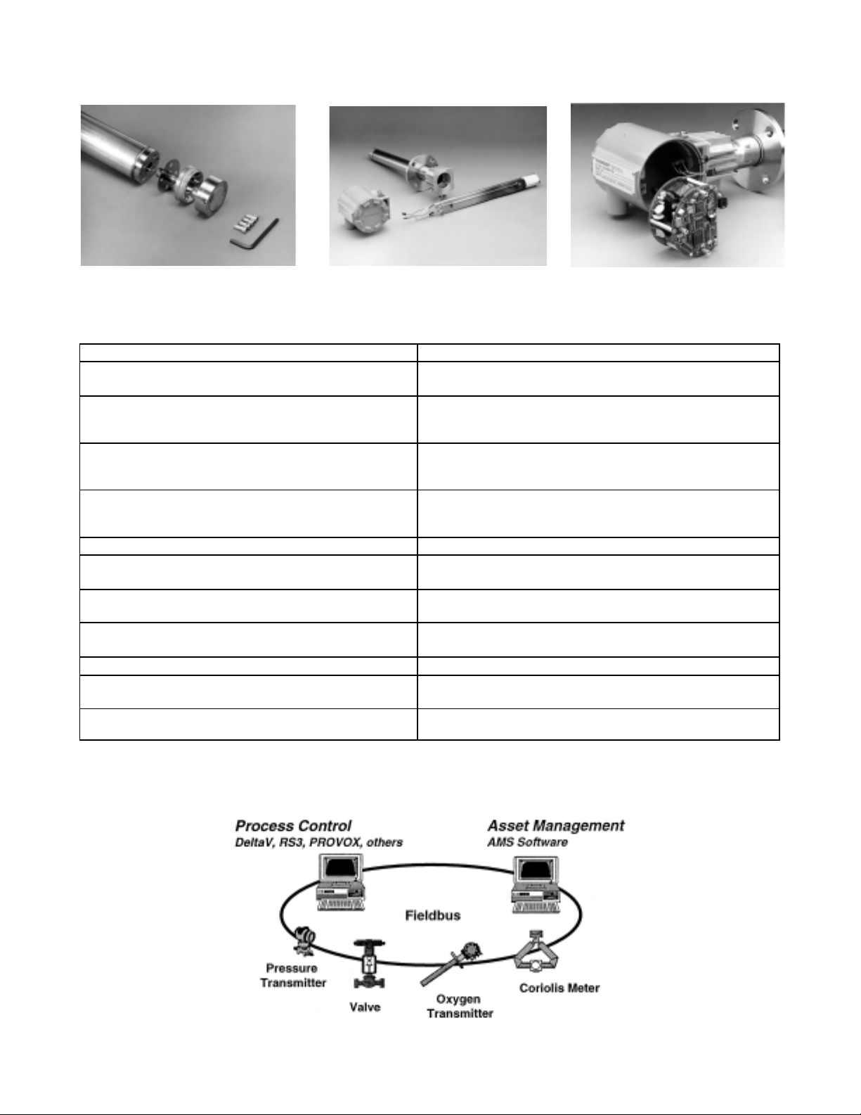
THE OXYMITTER 5000 OXYGEN TRANSMITTER IS COMPLETELY FIELD- REPAIRABLE
Sensor Cell
Assembly
Heater/Thermocouple
Assembly
Plug-In Electronics Module,
With Local Display/Keypad
OXYMITTER 5000 OXYGEN TRANSMITTER FEATURES AND BENEFITS
Features Benefits
FOUNDATION fieldbus communications All Information from analyzer is updated constantly, and
provided to the operator or technician. Low cost to maintain.
Rapid, accurate and reliable measurement of excess Provides inputs for significant fuel savings which normally
oxygen with a single in situ transmitter. pay for the analyzer in less than one year; best accuracy
specification in the industry!
Integrated oxygen probe and electronics simplifies Eliminates costs of mounting separate electronics.
installation. Eliminates cabling and conduit between probe and
electronics.
In situ design. No sample system, sample probes, Low installation and maintenance costs.
scrubbers, or pumps are necessary; test gas calibration
check without disturbing the probe.
Fast speed of response. In situ design ideal for closed loop control.
"Calibration recommended" indication. Online electrical Optimizes plant resources; reduces maintenance and
CAL check indicates need for calibration. calibration costs.
Field-replaceable cell, heater/thermocouple assembly Ease of maintenance.
and plug-in electronics module.
Suitable for use in process temperatures up to 1300°F Suitable for use in most combustion applications.
(700°C). Optionally up to 1832°F (1000°C).
Material of construction 316 LSS (all wetted parts). High resistance to corrosion.
Cell sensitivity increases logarithmically when oxygen Very useful for low oxygen levels.
decreases. Ideal for low excess air burners.
Automatic line voltage selections. Automatically selects from 85 to 265 VAC and 50/60 Hz.
without configuration or setup.
FOUNDATION fieldbus communications provides digital communications from field
device to field device over a single pair of wires.
Page 2
Page 3
SPECIFICATIONS
1
OXYMITTER 5000 OXYGEN TRANSMITTER
Net O2 Range 0-40% O
Accuracy: ±0.75% of reading or 0.05% O2,
whichever is greater
Lowest detectable limit - .05% O
System Response to Test Gas:
Initial response in less than
3 seconds
T
90
Temperature Limits:
Process: 32° to 1300°F (0° to 704°C)
up to 1832°F (1000°C) with
optional accessories
Electronics: -40° to 185°F (-40° to 85°C)
Operating temperature of
electronics inside of instrument
housing, as measured via Asset
Management Solutions software.
Probe Lengths, Nominal and Approximate Shipping
Weights:
18 in. (457 mm) package: 16 pounds (7.3 kg)
3 foot (0.91 m) package: 21 pounds (9.5 kg)
6 foot (1.83 m) package: 27 pounds (12.2 kg)
9 foot (2.74 m) package: 33 pounds (15.0 kg)
12 foot (3.66 m) package: 39 pounds (17.7 kg)
15 foot (4.6 m) package: 45 pounds (20.5 kg)
18 foot (5.5 m) package: 51 pounds (23 kg)
Mounting and Mounting Position:
Vertical or horizontal 12 inch (30 cm)
spool pieces are available to offset
transmitter housing from hot mounting
surfaces
(P/N 3D39761G02)
Materials:
Probe: Wetted or welded parts – 316L
stainless steel
Non-wetted parts – 304 stainless
steel, low-copper aluminum
Electronics
Enclosure: Low-copper aluminum
Calibration: Semi-automatic or automatic
Calibration Gas Mixtures
Recommended: 0.4% O
8% O2, balance N
(Ref. test gas kit #6296A27G01)
Calibration Gas
Flow: 5 scfh (2.5 l/m)
Reference Air: 2 scfh (1 l/m), clean, dry,
instrument-quality air (20.95% O
regulated to 5 psi (34 kPa)
2
in less than 8 seconds
, balance N
2
2
2
2
),
2
Electronics: NEMA 4X, IP 66 with fitting and pipe
on reference exhaust port to clean
dry atmosphere
Two 3/4” – 14 NPT conduit ports
Electrical Noise: Meets EN 50082-2 Electromagnetic
Compatibility Generic Immunity
Std., Part II
Includes ENG 1000 4-R for electrostatic discharge 4 Kv contact, 8 Kv
in air
Optionally ENG 1000 4-R "NamurIncreased" 8 Kv contact, 16 Kv in air
Includes IEC 801-4 fast transients-2
Kv on power supply and control lines
Hazardous Area
Certifications: NEC Class I, Div. 1, Groups B, C, D
CENELEC EExd II B + H2T2/T6
(electronics )
The Oxymitter 5000 complies with the
European Union PED 97/23/EC
Directive by virtue SEP.
ATEX compliant
Line Voltage: Universal 90 to 250 VAC, 48 to 62 Hz.
no switches or jumpers required 3/4"
– 14 NPT conduit port
Isolated Output: Digital
FOUNDATION fieldbus
Logic Signals: One logic I/O configured as a bi-
directional calibration handshake
signal optional calibration gas
sequencer.
5V, self-powered, 5 mA maximum
output
Fieldbus Logic:
Function Blocks: AI – execution time: 75 ms O
Heater temperature
2
Case temperature
Power Consumption Limits:
Power Consumption
of Probe Heater: 175 W nominal maximum
Power Consumption
of Electronics: 10 W nominal maximum
Fieldbus segment
power consumption: 17.5 mA
Emerson Process Management has satisfied all
obligations coming from the European legislation
to harmonize the product requirements in Europe.
1
All static performance characteristics are with operating variables constant. Specifications subject to change without notice.
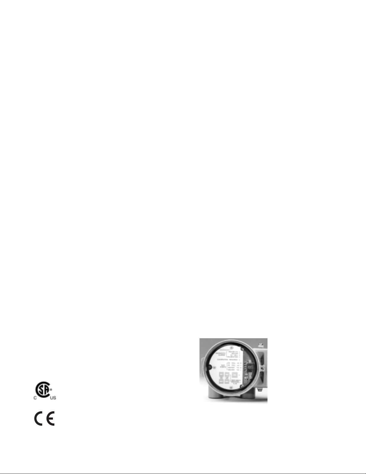
The Oxymitter 5000's field electronics mount directly to
the oxygen probe in a standard NEMA 4X, IP 66 housing.
Page 3
Page 4
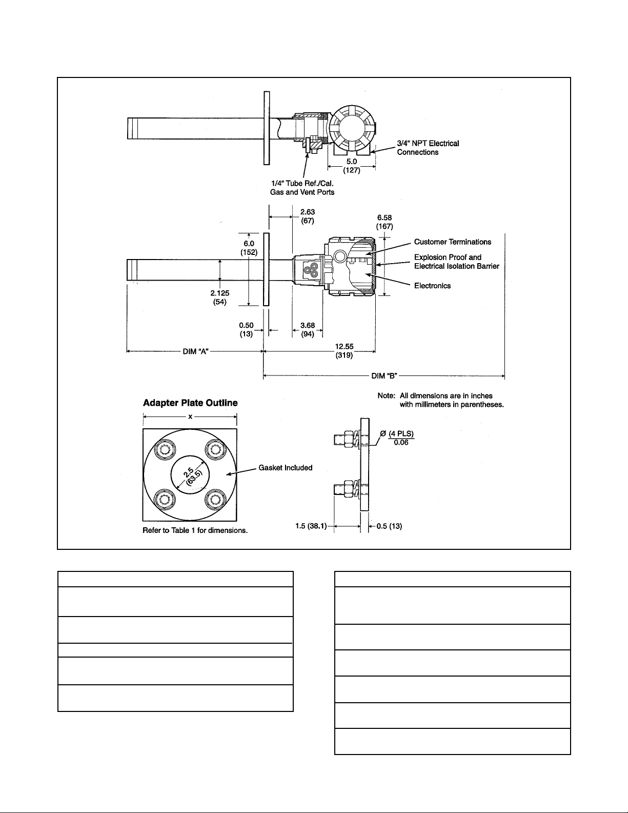
OUTLINE DIMENSIONS FOR OXYMITTER 5000 OXYGEN TRANSMITTER
Table I. Mounting Plate
Dimensions Dia. in. (mm)
ANSI DIN JIS
Flange (x) 6.00 7.5 6.5
(153) (190) (165)
Stud Size 5/8" – 11 M16 x 2 M12 x 1.75
4 Studs Eq. 4.75 BC 5.71 BC 5.71 BC
Sp. on BC
Flange (Y) 6.0 7.3 6.1
(153) (185) (155)
Page 4
Table II. Removal/Installation
Dim “A” Dim. “B”
Probe Insertion Removal
Length Depth Envelope
18 in. (457 mm) 16.00 32.38
Probes (407) (822)
3 ft. (0.91 m) 34.00 50.38
Probes (864) (1280)
6 ft. (1.83 m) 70.00 86.38
Probes (1778) (2194)
9 ft. (2.74 m) 106.00 122.38
Probes (2692) (3108)
12 ft. (3.66 m) 143.00 158.38
Probes (3607) (4023)
Page 5

ORDERING INFORMATION
OXT5A OXYMITTER 5000 IN SITU OXYGEN TRANSMITTER WITH FOUNDATION™ FIELDBUS COMMUNICATIONS
Oxygen Transmitter – Instruction Book
Code Sensing Probe Type
1 Ceramic diffusion element probe (ANSI) (N. American Std.)
2 Ceramic diffusion element flame arrestor probe (ANSI) (N. American Std.)
3 Snubber diffusion element (ANSI) (N. American Std.)
4 Ceramic diffusion element probe (DIN) (European Std.)
5 Snubber diffusion element flame arrestor probe (DIN) (European Std.)
6 Snubber diffusion element (DIN) (European Std.)
7 Ceramic diffusion element probe (JIS) (Japanese Std.)
8 Ceramic diffusion element probe flame arrestor probe (JIS) (Japanese Std.)
9 Snubber diffusion element (JIS) (Japanese Std.)
Code Probe Assembly
0 18 in. (457 mm) Probe
1 18 in. (457 mm) Probe with abrasive shield
2 3 ft. (0.91 m) Probe
3 3 ft. (0.91 m) Probe with abrasive shield
4 6 ft. (1.83 m) Probe
5 6 ft. (1.83 m) Probe with abrasive shield
6 9 ft. (2.74 m) Probe
7 9 ft. (2.74 m) Probe with abrasive shield
8 12 ft. (3.66 m) Probe
1
9 12 ft. (3.66 m) Probe with abrasive shield
A 15 ft. (4.6m) Probe with abrasive shield
B 18 ft. (5.5 m) Probe with abrasive shield
1
1
1
1
1
1
1
Code Mounting Hardware – Stack Side
0 No adaptor plate (“0” must also be chosen under “Mounting hardware – probe side” below)
1 New installation – square weld plate with studs
2 Mounting to Model 218 mounting plate (with Model 218 shield removed)
3 Mounting to existing Model 218 support shield
4 Competitor’s mounting
2
5 Mounting to Model 132 adapter plate
Code Mounting Hardware – Probe Side
0 No mounting hardware/no adaptor plate
1 Probe only (ANSI) (N. American Std.)
2 New bypass or new abrasive shield (ANSI) (N. American Std.)
4 Probe only (DIN) (European Std.)
5 New bypass or new abrasive shield (DIN) (European Std.)
7 Probe only (JIS) (Japanese Std.)
8 New bypass or new abrasive shield (JIS) (Japanese Std.)
Code Electronic Housing – NEMA 4X, IP 66
11 Standard filtered termination
12 Transient protected filtered termination
OXT5A 3 2 1 1 12 Cont’d Example
Note:
1
Recommended usages: high velocity particulates in flue stream, installation within 3.5 m (10 ft.) of soot blowers or heavy salt cake build up.
Applications: pulverized coal, recovery boilers, lime kiln. Regardless of application, abrasive shields with support brackets are recommended for
9 ft. (2.74 m) and 12 ft. (3.66 m) probe installations, particularly horizontal installations.
2
Where possible, specify SPS number; otherwise provide details of existing mounting plate as follows:
Plate with studs Bolt circle diameter, number and arrangement of studs, stud thread, stud height above mounting plate.
Plate without studs Bolt circle diameter, number and arrangement of holes, thread, depth of stud mounting plate with accessories.
Page 5
Page 6

ORDERING INFORMATION (Continued)
Cont’d Code Communications/Operator Interface
1 Membrane keypad – fieldbus
Code Language
1 English
2 German
3 French
4 Spanish
5 Italian
Code Termination Filtering
00 No option – specified as part of electronic housing
Code Calibration Accessories
00 No hardware
01 Cal. gas rotometer and reference gas set
02 Intelligent multiprobe sequencer Refer to Table 2
XX Single probe sequencer, mounted to Oxymitter Refer to Table 1
Code Basic Control Suite Functionality
00 Basic control suite
01 Deduct basic control suite
Cont’d 1 1 00 02 00
3
Start-up, calibration and operation can be implemented using the standard membrane keypad. Remote access and additional functionality available via fieldbus
communications (DeltaV™)
3
TABLE 1
ENTRY CODE NO YES BRASS/TEFLON STAINLESS STEEL HORIZONTAL VERTICAL
REFERENCE AIR SET FITTINGS/TUBING OXYMITTER MOUNTING
03 X X X
04 X X X
05 X X X
06 X X X
07 X X X
08 X X X
09 X X X
10 X X X
TABLE 2
LIST PART NUMBERS AS SEPARATE LINE ITEMS:
The Intelligent Multiprobe Sequencer (IMPS) will automatically calibrate up to 4 probes.
Part Number Description Number of Probes
3D39695G01 Intelligent Multiprobe Sequencer (IMPS) 1
3D39695G02 Intelligent Multiprobe Sequencer (IMPS) 2
3D39695G03 Intelligent Multiprobe Sequencer (IMPS) 3
3D39695G04 Intelligent Multiprobe Sequencer (IMPS) 4
3D39695G05 Intelligent Multiprobe Sequencer (IMPS) w/115 V heater 1
3D39695G06 Intelligent Multiprobe Sequencer (IMPS) w/115 V heater 2
3D39695G07 Intelligent Multiprobe Sequencer (IMPS) w/115 V heater 3
3D39695G08 Intelligent Multiprobe Sequencer (IMPS) w/115V heater 4
3D39695G09 Intelligent Multiprobe Sequencer (IMPS) w/220 V heater 1
3D39695G10 Intelligent Multiprobe Sequencer (IMPS) w/220 V heater 2
3D39695G11 Intelligent Multiprobe Sequencer (IMPS) w/220 V heater 3
3D39695G12 Intelligent Multiprobe Sequencer (IMPS) w/220 V heater 4
Rosemount Analytical no longer offers an integral Z-purge option for its oxygen (O2) analyzers. However, the IFT, MPS and IMPS
enclosures are still capable of Z or X purge by the customer.
CALIBRATION GAS BOTTLES
1
Part Number Description
1A99119G01 Two disposable calibration gas bottles – .4% and 8% O2 balance nitrogen 550 liters each
1A99119G02 Two flow regulators for cal. gas bottles
1A99119G03 Bottle rack
1
Bottles cannot be shipped via airfreight.
* When used with “calibration recommended” feature, bottles should provide 2 to 3 years of calibrations in normal service.
Page 6
Page 7

OUTLINE DIMENSIONS FOR OXYMITTER 5000 HAZARDOUS AREA OXYGEN
TRANSMITTER
6.58
(167)
0.50
(13)
Table I. Mounting Plate
Dimensions Dia. in. (mm)
ANSI DIN
Mtg. Plate (x) 7.75 8.5
(197) (215)
Stud Size 5/8" – 11 M16 x 2
4 Studs Eq. 6.00 BC 6.69 BC
Sp. on BC (152.4) BC (170) BC
Flange (Y) 7.5 6.7
(190) (170)
Table II. Removal/Installation
Dim “A” Dim. “B”
Probe Insertion Removal
Length Depth Envelope
18 in. (457 mm) 18.1 31.6
Probes (460) (803)
3 ft. (0.91 m) 36.1 57.0
Probes (917) (1448)
6 ft. (1.83 m) 72.1 85.6
Probes (1831) (2174)
Page 7
Page 8

ORDERING INFORMATION
OXT5C OXYMITTER 5000 EXPLOSION PROOF – IN SITU OXYGEN TRANSMITTER
Explosion Proof Oxygen Transmitter – Instruction Book
Code Sensing Probe Type with Flame Arrester
1 Ceramic diffusion element probe (ANSI 3 inch 150 lb.)
2 Snubber diffusion element (ANSI 3 inch 150 lb.)
3 Ceramic diffusion element probe (DIN 2527) – 1/4" tube fittings
4 Snubber diffusion element (DIN 2527) – 1/4" tube fittings
5 Ceramic diffusion element probe (JIS)
6 Snubber diffusion element (JIS)
7 Ceramic diffusion element probe (ANSI 3 inch 300 lb. flange)
Code Probe Assembly
0 18 in. probe
1 18 in. probe with 3 ft. bypass
2 18 in. probe with abrasive shield
3 3 ft. probe
4 3 ft. probe with abrasive shield
5 6 ft. probe
6 6 ft. probe with abrasive shield
Code Mounting Adapter – Stack Side
0 No adapter plate ("0" must also be chosen under "Mounting adapter – probe side" below)
1 New installation – square weld plate with studs
2 Model 218 mounting plate (with Model 218 shield removed)
3 Competitor's mount
1
1
1
2
Code Mounting Adapter – Probe Side
0 No adapter plate
1 Probe only (ANSI)
2 New bypass or new abrasive shield (ANSI)
4 Probe only (DIN)
5 New bypass or new abrasive shield (DIN)
7 Probe only (JIS)
8 New bypass or new abrasive shield (JIS)
Code Electronic Housing – NEMA 4X, IP 66
11 Standard filtered termination
12 Transient protected filtered termination
Code Operator Interface
3
1 Membrane keypad – FOUNDATION fieldbus
Code Language
1 English
2 German
3 French
4 Spanish
5 Italian
OXT5C 3 3 1 1 11 1 1 (Cont'd) EXAMPLE
Page 8
Page 9

ORDERING INFORMATION (Continued)
(Cont’d) Code Termination Filtering
00 No option – specified as part of electronic housing
Code Calibration Accessories
00 No hardware
01 Cal./ref. flowmeters and reference pressure regulator
02 IMPS 4000 (safe area only) Refer to Table 1
03 SPS 4000 remote mounted (safe area only) Refer to SPS matrix
Code Hazardous Area Approval
10 CENELEC – EEx d II B + H2T2/T6 (electronics)
20 CSA – Class I, Div. 1, Groups B, C and D Code T2/T6 (electronics)
Code Basic Control Suite Functionality
00 Basic control suite
01 Deduct basic control suite
Cont’d 00 01 10 00
NOTES:
1
Recommended usages: high velocity particulates in flue stream, installation within 3.5 m (10 ft.) of soot blowers or heavy salt cake build up.
Applications: pulverized coal, recovery boilers, lime kiln. Regardless of application, abrasive shields with support brackets are recommended for
9 ft. (2.74 m) and 12 ft. (3.66 m) probe installations, particularly horizontal installations.
2
Where possible specify SPS number; otherwise provide details of existing mounting plate as follows:
Plate with studs Bolt circle diameter, number and arrangement of studs, stud thread, stud height above mounting plate.
Plate without studs Bolt circle diameter, number and arrangement of holes, thread, depth of stud mounting plate with accessories.
3
Start-up, calibration and operation can be implemented using the standard membrane keypad. Remote access and additional functionality
available via FOUNDATION fieldbus communications (DeltaV™)
High Sulfur Service
For high sulfur applications, please add note to your purchase order requesting high sulfur cell part number 4847B63G02 in lieu of the
standard ZrO2 cell. Price adder is required.
Cell replacement kits for high sulfur service are also available. Consult part number 4849B94GXX in the Combustion Solutions Center
Spare Parts list.
TABLE 1
IMPS – Safe Area Only
LIST PART NUMBERS AS SEPARATE LINE ITEMS:
The Intelligent Multiprobe Sequencer (IMPS) will automatically calibrate up to 4 probes.
Part Number Description Number of Probes
3D39695G01 Intelligent multiprobe sequencer (IMPS) 1
3D39695G02 Intelligent multiprobe sequencer (IMPS) 2
3D39695G03 Intelligent multiprobe sequencer (IMPS) 3
3D39695G04 Intelligent multiprobe sequencer (IMPS) 4
3D39695G05 Intelligent multiprobe sequencer (IMPS) w/115 V heater 1
3D39695G06 Intelligent multiprobe sequencer (IMPS) w/115 V heater 2
3D39695G07 Intelligent multiprobe sequencer (IMPS) w/115 V heater 3
3D39695G08 Intelligent multiprobe sequencer (IMPS) w/115V heater 4
3D39695G09 Intelligent multiprobe sequencer (IMPS) w/220 V heater 1
3D39695G10 Intelligent multiprobe sequencer (IMPS) w/220 V heater 2
3D39695G11 Intelligent multiprobe sequencer (IMPS) w/220 V heater 3
3D39695G12 Intelligent multiprobe sequencer (IMPS) w/220 V heater 4
Page 9
Page 10

OXYMITTER 4000 ACCESSORIES
HART® Handheld 275 Communicator
The HART® 275 Communicator is an interface device
that provides a common communication link to HART
compatible instruments, such as the Sulfur-Resistant
Oxymitter 4000. HART
®
Communications Protocol
permits all the information available from the SulfurResistant Oxymitter 4000's electronics to be transmitted
over standard 4-20 mA signal wires. By attaching the
HART handheld communicator at a termination point
along the 4-20 mA signal line, a technician can diagnose
problems and configure and calibrate the SulfurResistant Oxymitter 4000 as if he or she were standing in
front of the instrument.
For more information, call Rosemount Analytical at
1-800-433-6076.
Bypass Packages
The specially designed Rosemount Analytical Bypass
Package for oxygen analyzers has proven to withstand
the high temperatures in process heaters while providing
the same advantages offered by the in situ sensor.
Inconel tubes provide effective resistance to corrosion,
and the other components common to other sampling
systems.
For more information, call Rosemount Analytical at
1-800-433-6076.
®
O2 Calibration Gas Kits
Rosemount Analytical's O2 Calibration Gas and Service
Kits have been carefully designed to provide a more
convenient and fully portable means of testing, calibrating, and servicing Rosemount Analytical's oxygen
analyzers. These lightweight, disposable gas cylinders
eliminate the need to rent gas bottles.
For more information, call Rosemount Analytical at
1-800-433-6076.
Page 10
Page 11

Page 11
Page 12

The contents of this publication are presented for informational purposes only, and while every effort has been made to ensure their accuracy, they are not to
be construed as warranties or guarantees, express or implied, regarding the products or services described herein or their use or applicability. All sales are
governed by our terms and conditions, which are available on request. We reserve the right to modify or improve the designs or specifications of our products
at any time without notice.
Emerson Process Management
Rosemount Analytical Inc.
Process Analytic Division
1201 North Main Street
P. O . B o x 9 0 1
Orrville, OH 44667-0901 USA
T 330.682.9010
Toll Free in US and Canada 800.433.6076
F 330.684.4434
e-mail : gas.csc@EmersonProcess.com
www.processanalytic.com
© Rosemount Analytical Inc., 2003. All rights reserved.
Printed in U .S . A. on recy cled pa per.
 Loading...