

Page 1
Instruction Manual
IM-106-340, Rev 4.2
July 2008
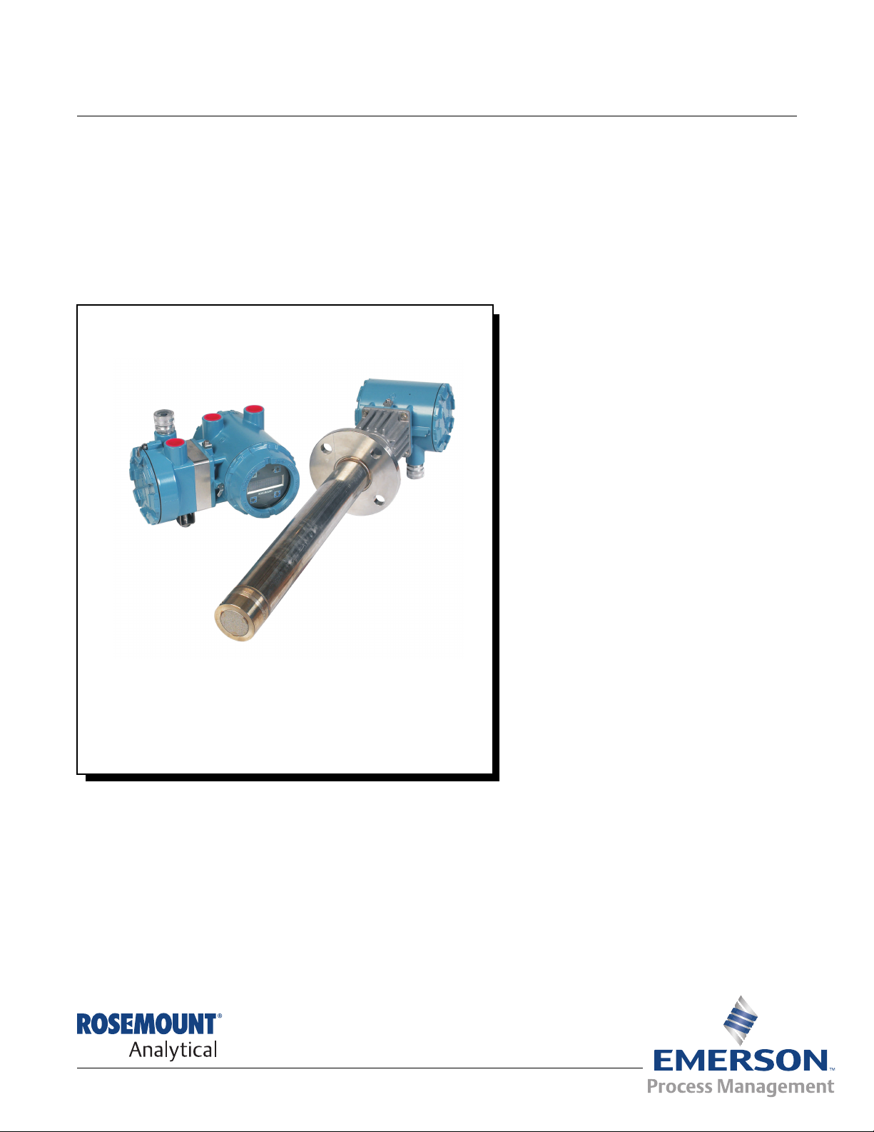
Oxymitter 4000
Oxygen Transmitter
http://www.raihome.com
Page 2

Page 3

HIGHLIGHTS OF CHANGES
Effective May 31, 2006 Rev. 4.0
Page Summary
General Reformatted entire manual from a two column layout. Removed all references to JIS
specifications. Replaced SPS 4000 information with SPS 4001B information.
Cover Updated photo, revision number and date.
viii Removed Figure 3. Oxymitter 4000 with SPS 4000 Wiring Diagram from Quick Start
Guide.
1-2 Revised Figure 1-1 to show SPS 4001B and updated IMPS 4000.
1-5 Revised Figure 1-2 to show SPS 4001B.
1-8 Added step 11 and Figure 1-6.
1-10, 1-11 Revised Figure 1-8 and Figure 1-9 to show SPS 4001B.
1-12 Removed Components paragraph.
1-13 Removed Figure 1-9. SPS 4000.
1-15 Updated Figure 1-14. Abrasive Shield Assembly.
1-16, 1-17 Revised Specifications.
1-18, 1-19 Revised Product Matrix table.
2-1 Added two additional warnings.
2-5 Removed Figure 2-3. Oxymitter 4000 Installation (with SPS 4000).
2-12, 2-15 Revised Figure 2-9 and Figure 2-10 to show grounding locations.
2-16 Revised Install Interconnecting Cable paragraph. Removed Electrical Installation (For
Oxymitter 4000 with SPS 400).
2-18 Added SPS 4001B Connections.
3-1, 4-1 Revised Terminal Block Wiring text.
5-2 Added Reference Air information.
7-9 Added D/A Trim Procedure.
8-3 Revised Alarm Indications to include signal alarm levels.
8-23 Removed SPS 4000 Troubleshooting.
9-8, 9-9 Revised Figure 9-3 and Figure 9-4.
9-11, 9-13 Revised Figure 9-6 and Figure 9-7 with updated circuit board.
9-17 Revised Figure 9-10.
9-20 Removed SPS 4000 Maintenance and Component Replacement.
10-3, 10-4 Updated part numbers for the Cell Replacement Kit, ANSI 15’ and 18’.
10-4 Updated part numbers for the Contact and Thermocouple Replacement Assembly, 15’ and
18’.
Page 4

HIGHLIGHTS OF CHANGES (CONTINUED)
Effective May 31, 2006 Rev. 4.0 (Continued)
Page Summary
10-5 Removed Ceramic Diffuser Hub Assy. Changed part numbers 4851B89G04 and
4851B90G04 to 10 microns.
10-6 Revised Table 10-2. Removed Replacement Parts for SPS 4000 table.
11-4 Revised Figure 11-4 to show the SPS 4001B.
11-6 Added Figure 11-7 and explanation of the Oxybalance Display and Averaging System.
A-21 Added General Precautions for Handling and Storing High Pressure Gas Cylinders.
Effective January 2007 Rev. 4.1
Page Summary
General Revised reference air specifications to read 1 l/min (2 scfh) throughout the manual.
Page 8-22 Added the paragraph and procedural steps after 'Heater Not Open, but Unable to Reach
736°C Setpoint.
Page A-2 thru A-24 Added note 11 to the safety data section. Added new language translations.
Page B-1 Updated the return of materials address.
Back cover Updated the address blocks.
'
Effective July 2008 Rev. 4.2
Page Summary
Page 6-4 Added note regarding cleaning the LOI screen before use.
Page 5

Instruction Manual
IM-106-340, Rev 4.2
July 2008
Oxymitter 4000
Table of Contents
Essential Instructions . . . . . . . . . . . . . . . . . . . . . . . . . . . . . . . . . . . . . . . . i
SECTION i
Introduction
SECTION 1
Description and
Specifications
Preface. . . . . . . . . . . . . . . . . . . . . . . . . . . . . . . . . . . . . . . . . . . . . . . . . . iv
Definitions . . . . . . . . . . . . . . . . . . . . . . . . . . . . . . . . . . . . . . . . . . . . . . . iv
Symbols . . . . . . . . . . . . . . . . . . . . . . . . . . . . . . . . . . . . . . . . . . . . . . . . . iv
What You Need To Know. . . . . . . . . . . . . . . . . . . . . . . . . . . . . . . . . . . . v
Can You Use the Quick Start Guide? . . . . . . . . . . . . . . . . . . . . . . . . . .vii
Quick Start Guide for Oxymitter 4000 Systems . . . . . . . . . . . . . . . . . . viii
Quick Reference Guide Manual Calibration Instructions . . . . . . . . . . . . ix
HART Communicator Fast Key Sequences. . . . . . . . . . . . . . . . . . . . . . x
Component Checklist. . . . . . . . . . . . . . . . . . . . . . . . . . . . . . . . . . . . . .1-1
System Overview . . . . . . . . . . . . . . . . . . . . . . . . . . . . . . . . . . . . . . . . .1-1
Scope . . . . . . . . . . . . . . . . . . . . . . . . . . . . . . . . . . . . . . . . . . . . . . .1-1
System Description. . . . . . . . . . . . . . . . . . . . . . . . . . . . . . . . . . . . .1-3
System Configuration . . . . . . . . . . . . . . . . . . . . . . . . . . . . . . . . . . .1-4
System Features. . . . . . . . . . . . . . . . . . . . . . . . . . . . . . . . . . . . . . .1-4
Handling the Oxymitter 4000 . . . . . . . . . . . . . . . . . . . . . . . . . . . . .1-8
System Considerations . . . . . . . . . . . . . . . . . . . . . . . . . . . . . . . . . .1-9
IMPS 4000 (Optional). . . . . . . . . . . . . . . . . . . . . . . . . . . . . . . . . . . . .1-12
SPS 4001B (Optional) . . . . . . . . . . . . . . . . . . . . . . . . . . . . . . . . . . . .1-12
Mounting . . . . . . . . . . . . . . . . . . . . . . . . . . . . . . . . . . . . . . . . . . . .1-12
Operation . . . . . . . . . . . . . . . . . . . . . . . . . . . . . . . . . . . . . . . . . . .1-12
Model 751 Remote Powered Loop LCD Display . . . . . . . . . . . . . . . .1-13
Probe Options . . . . . . . . . . . . . . . . . . . . . . . . . . . . . . . . . . . . . . . . . .1-13
Diffusion Elements . . . . . . . . . . . . . . . . . . . . . . . . . . . . . . . . . . . .1-13
Specifications. . . . . . . . . . . . . . . . . . . . . . . . . . . . . . . . . . . . . . . . . . .1-16
SECTION 2
Configuration of
Oxymitter 4000
with Membrane
Keypad
SECTION 3
Installation
Verify Installation . . . . . . . . . . . . . . . . . . . . . . . . . . . . . . . . . . . . . . . . .2-1
Mechanical Installation . . . . . . . . . . . . . . . . . . . . . . . . . . . . . . . . . .2-1
Terminal Block Wiring. . . . . . . . . . . . . . . . . . . . . . . . . . . . . . . . . . .2-1
Oxymitter 4000 Configuration. . . . . . . . . . . . . . . . . . . . . . . . . . . . .2-2
Logic I/O. . . . . . . . . . . . . . . . . . . . . . . . . . . . . . . . . . . . . . . . . . . . . . . .2-5
Recommended Configuration. . . . . . . . . . . . . . . . . . . . . . . . . . . . .2-6
Mechanical Installation. . . . . . . . . . . . . . . . . . . . . . . . . . . . . . . . . . . . .3-2
Selecting Location. . . . . . . . . . . . . . . . . . . . . . . . . . . . . . . . . . . . . .3-2
Probe Installation . . . . . . . . . . . . . . . . . . . . . . . . . . . . . . . . . . . . . .3-2
Remote Electronics Installation. . . . . . . . . . . . . . . . . . . . . . . . . . . .3-9
Electrical Installation (with Integral Electronics). . . . . . . . . . . . . . . . .3-10
Electrical Installation (with Remote Electronics) . . . . . . . . . . . . . . . .3-13
Install Interconnecting Cable. . . . . . . . . . . . . . . . . . . . . . . . . . . . .3-16
Pneumatic Installation . . . . . . . . . . . . . . . . . . . . . . . . . . . . . . . . . . . .3-16
IMPS 4000 Connections . . . . . . . . . . . . . . . . . . . . . . . . . . . . . . . . . .3-18
SPS 4001B Connections . . . . . . . . . . . . . . . . . . . . . . . . . . . . . . . . . .3-18
TOC-1
Page 6

Oxymitter 4000
Instruction Manual
IM-106-340, Rev 4.2
July 2008
SECTION 4
Configuration of
Oxymitter 4000 with LOI
SECTION 5
Startup and Operation of
Oxymitter 4000 with
Membrane Keypad
SECTION 6
Startup and Operation of
Oxymitter 4000 with LOI
Verify installation . . . . . . . . . . . . . . . . . . . . . . . . . . . . . . . . . . . . . . . . . 4-1
Mechanical Installation . . . . . . . . . . . . . . . . . . . . . . . . . . . . . . . . . . 4-1
Terminal Block Wiring. . . . . . . . . . . . . . . . . . . . . . . . . . . . . . . . . . . 4-1
Oxymitter 4000 Configuration. . . . . . . . . . . . . . . . . . . . . . . . . . . . . 4-2
Logic I/O . . . . . . . . . . . . . . . . . . . . . . . . . . . . . . . . . . . . . . . . . . . . . . . 4-4
Recommended Configuration. . . . . . . . . . . . . . . . . . . . . . . . . . . . . 4-6
Power Up. . . . . . . . . . . . . . . . . . . . . . . . . . . . . . . . . . . . . . . . . . . . . . . 5-1
Operation. . . . . . . . . . . . . . . . . . . . . . . . . . . . . . . . . . . . . . . . . . . . . . . 5-2
Overview. . . . . . . . . . . . . . . . . . . . . . . . . . . . . . . . . . . . . . . . . . . . . 5-2
Power Up. . . . . . . . . . . . . . . . . . . . . . . . . . . . . . . . . . . . . . . . . . . . . . . 6-1
Start Up Oxymitter 4000 Calibration . . . . . . . . . . . . . . . . . . . . . . . . . . 6-3
Navigating the Local Operator Interface . . . . . . . . . . . . . . . . . . . . . . . 6-3
Overview. . . . . . . . . . . . . . . . . . . . . . . . . . . . . . . . . . . . . . . . . . . . . 6-3
Lockout. . . . . . . . . . . . . . . . . . . . . . . . . . . . . . . . . . . . . . . . . . . . . . 6-3
LOI Key Designations . . . . . . . . . . . . . . . . . . . . . . . . . . . . . . . . . . . . . 6-4
LOI Menu Tree. . . . . . . . . . . . . . . . . . . . . . . . . . . . . . . . . . . . . . . . . . . 6-4
Oxymitter 4000 Setup at the LOI. . . . . . . . . . . . . . . . . . . . . . . . . . . . . 6-6
LOI Installation. . . . . . . . . . . . . . . . . . . . . . . . . . . . . . . . . . . . . . . . . . . 6-9
Oxymitter 4000 Test Points . . . . . . . . . . . . . . . . . . . . . . . . . . . . . . . . 6-10
Remote Powered Loop LCD Display (Optional) . . . . . . . . . . . . . . . . 6-10
SECTION 7
HART/AMS
SECTION 8
Troubleshooting
SECTION 9
Maintenance and Service
Overview . . . . . . . . . . . . . . . . . . . . . . . . . . . . . . . . . . . . . . . . . . . . . . . 7-1
HART Communicator Signal Line Connections. . . . . . . . . . . . . . . . . . 7-2
HART Communicator PC Connections . . . . . . . . . . . . . . . . . . . . . . . . 7-2
Off-Line and On-Line Operations. . . . . . . . . . . . . . . . . . . . . . . . . . . . . 7-4
Logic I/O Configurations . . . . . . . . . . . . . . . . . . . . . . . . . . . . . . . . . . . 7-4
HART/AMS Menu Tree . . . . . . . . . . . . . . . . . . . . . . . . . . . . . . . . . . . . 7-4
HART Communicator O2 Cal Method . . . . . . . . . . . . . . . . . . . . . . . . . 7-8
Defining a Timed Calibration via HART. . . . . . . . . . . . . . . . . . . . . . . . 7-9
D/A Trim Procedure. . . . . . . . . . . . . . . . . . . . . . . . . . . . . . . . . . . . . . . 7-9
Overview . . . . . . . . . . . . . . . . . . . . . . . . . . . . . . . . . . . . . . . . . . . . . . . 8-1
General . . . . . . . . . . . . . . . . . . . . . . . . . . . . . . . . . . . . . . . . . . . . . . . . 8-3
Alarm Indications . . . . . . . . . . . . . . . . . . . . . . . . . . . . . . . . . . . . . . . . . 8-3
Alarm Contacts . . . . . . . . . . . . . . . . . . . . . . . . . . . . . . . . . . . . . . . . . . 8-4
Identifying and Correcting Alarm Indications . . . . . . . . . . . . . . . . . . . . 8-5
Heater Not Open, but Unable to Reach 736°C Setpoint . . . . . . . . . . 8-22
Calibration Passes, but Still Reads Incorrectly . . . . . . . . . . . . . . . . . 8-22
Overview . . . . . . . . . . . . . . . . . . . . . . . . . . . . . . . . . . . . . . . . . . . . . . . 9-1
Calibration with Keypad. . . . . . . . . . . . . . . . . . . . . . . . . . . . . . . . . . . . 9-1
Automatic Calibration . . . . . . . . . . . . . . . . . . . . . . . . . . . . . . . . . . . 9-2
Semi-Automatic Calibration . . . . . . . . . . . . . . . . . . . . . . . . . . . . . . 9-3
Manual Calibration with Membrane Keypad. . . . . . . . . . . . . . . . . . 9-3
Calibration with LOI . . . . . . . . . . . . . . . . . . . . . . . . . . . . . . . . . . . . . . . 9-5
Oxymitter 4000 Repair. . . . . . . . . . . . . . . . . . . . . . . . . . . . . . . . . . . . . 9-7
Removal and Replacement of Probe . . . . . . . . . . . . . . . . . . . . . . . 9-7
TOC-2
Page 7

Instruction Manual
IM-106-340, Rev 4.2
July 2008
Oxymitter 4000
SECTION 10
Replacement Parts
SECTION 11
Optional
Accessories
APPENDIX A
Safety Data
APPENDIX B
Return of Material
Probe Replacement Parts . . . . . . . . . . . . . . . . . . . . . . . . . . . . . . . . .10-1
Electronics Replacement Parts . . . . . . . . . . . . . . . . . . . . . . . . . . . . .10-6
HART Handheld 375 Communicator . . . . . . . . . . . . . . . . . . . . . . . . .11-1
Asset Management Solutions (AMS) . . . . . . . . . . . . . . . . . . . . . . . . .11-2
By-Pass Packages. . . . . . . . . . . . . . . . . . . . . . . . . . . . . . . . . . . . . . .11-2
IMPS 4000 Intelligent Multiprobe Test Gas Sequencer . . . . . . . . . . .11-3
SPS 4001B Single Probe Autocalibration Sequencer . . . . . . . . . . . .11-4
O2 Calibration Gas. . . . . . . . . . . . . . . . . . . . . . . . . . . . . . . . . . . . . . .11-5
Catalyst Regeneration . . . . . . . . . . . . . . . . . . . . . . . . . . . . . . . . . . . .11-6
OxyBalance Display and Averaging System . . . . . . . . . . . . . . . . . . .11-6
Safety Instructions . . . . . . . . . . . . . . . . . . . . . . . . . . . . . . . . . . . . . . . A-2
Safety Data Sheet for Ceramic Fiber Products . . . . . . . . . . . . . . . . A-24
. . . . . . . . . . . . . . . . . . . . . . . . . . . . . . . . . . . . . . . . . . . . . . . . . . . . . A-30
Returning Material . . . . . . . . . . . . . . . . . . . . . . . . . . . . . . . . . . . . . . . B-1
TOC-3
Page 8

Oxymitter 4000
Instruction Manual
IM-106-340, Rev 4.2
July 2008
TOC-4
Page 9

Instruction Manual
IM-106-340, Rev. 4.2
July 2008
Oxymitter 4000
Oxymitter Oxygen Transmitters
READ THIS PAGE BEFORE PROCEEDING!
ESSENTIAL INSTRUCTIONS
Emerson Process Management designs, manufactures and tests its products
to meet many national and international standards. Because these
instruments are sophisticated technical products, you MUST properly
install, use, and maintain them to ensure they continue to operate within
their normal specifications. The following instructions MUST be adhered to
and integrated into your safety program when installing, using, and
maintaining Emerson’s Rosemount Analytical products. Failure to follow the
proper instructions may cause any one of the following situations to occur:
Loss of life; personal injury; property damage; damage to this instrument; and
warranty invalidation.
• Read all instructions prior to installing, operating, and servicing the
product.
• If you do not understand any of the instructions, contact your
Emerson Process Management representative for clarification.
• Follow all warnings, cautions, and instructions marked on and
supplied with the product.
• Inform and educate your personnel in the proper installation,
operation, and maintenance of the product.
• Install your equipment as specified in the Installation Instructions
of the appropriate Instruction Manual and per applicable local and
national codes. Connect all products to the proper electrical and
pressure sources.
• To ensure proper performance, use qualified personnel to install,
operate, update, program, and maintain the product.
• When replacement parts are required, ensure that qualified people use
replacement parts specified by Emerson Process Management.
Unauthorized parts and procedures can affect the product's
performance, place the safe operation of your process at risk, and
VOID YOUR WARRANTY. Look-alike substitutions may result in fire,
electrical hazards, or improper operation.
• Ensure that all equipment doors are closed and protective covers
are in place, except when maintenance is being performed by
qualified persons, to prevent electrical shock and personal injury.
http://www.raihome.com
The information contained in this document is subject to change without
notice.
If a Model 275/375 Universal HART® Communicator is used with this unit, the software
within the Model 275/375 may require modification. If a software modification is required,
please contact your local Emerson Process Management Service Group or National
Response Center at 1-800-433-6076 or 1-888-433-6829.
Page 10

Oxymitter 4000
Instruction Manual
IM-106-340, Rev. 4.2
July 2008
ii
Page 11

Instruction Manual
IM-106-340, Rev. 4.2
July 2008
Section i Introduction
Preface . . . . . . . . . . . . . . . . . . . . . . . . . . . . . . . . . . . . . . . . . page iv
Definitions . . . . . . . . . . . . . . . . . . . . . . . . . . . . . . . . . . . . . .page iv
Symbols . . . . . . . . . . . . . . . . . . . . . . . . . . . . . . . . . . . . . . . . page iv
What You Need To Know . . . . . . . . . . . . . . . . . . . . . . . . . . page v
Can You Use the Quick Start Guide? . . . . . . . . . . . . . . . .page vii
Quick Start Guide for Oxymitter 4000 Systems . . . . . . . . page viii
Quick Reference Guide Manual Calibration Instructions page ix
HART Communicator Fast Key Sequences . . . . . . . . . . . page x
Oxymitter 4000
http://www.raihome.com
Page 12
Oxymitter 4000
RISKOFELECTRICAL SHOCK
WARNING:REFER TOINSTRUCTIONMANUAL
PROTECTIVECONDUCT OR TERMINAL
EARTH(GROUND) TERMINAL
:
:
:
:
Instruction Manual
IM-106-340, Rev. 4.2
July 2008
PREFACE
DEFINITIONS
The purpose of this manual is to provide information concerning the
components, functions, installation and maintenance of the Oxymitter 4000
Oxygen Transmitter.
Some sections may describe equipment not used in your configuration. The
user should become thoroughly familiar with the operation of this module
before operating it. Read this instruction manual completely.
The following definitions apply to WARNINGS, CAUTIONS, and NOTES
found throughout this publication.
Highlights an operation or maintenance procedure, practice, condition, statement, etc. If not
strictly observed, could result in injury, death, or long-term health hazards of personnel.
Highlights an operation or maintenance procedure, practice, condition, statement, etc. If not
strictly observed, could result in damage to or destruction of equipment, or loss of
effectiveness.
NOTE
Highlights an essential operating procedure, condition, or statement.
SYMBOLS
NOTE TO USERS
The number in the lower right corner of each illustration in this publication is a
manual illustration number. It is not a part number, and is not related to the
illustration in any technical manner.
iv
Page 13
Instruction Manual
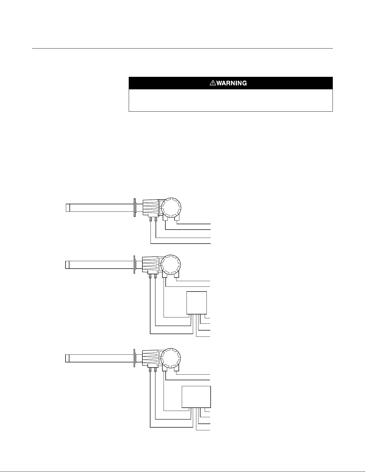
Cal.Gas1
Cal.Gas1
Cal.Gas
Cal.Gas
Cal.Gas2
Cal.Gas2
4-20mA
4-20mA
OXYMITTER4000
OXYMITTER4000WITH
SPS4001B
OXYMITTER4000WITHREMOTE
IMPS4000OPTION
IMPS
4000
LineVoltage
LineVoltage
LineVoltage
LineVoltage
LineVoltage
4-20mA
Instr. Air(Ref. Air)
Cal.Gas
LOGICI/O
LOGICI/O
Instr. Air(Ref. Air)
Instr. Air(Ref. Air)
Ref. Air
Ref. Air
38890001
SPS
4001B
IM-106-340, Rev. 4.2
July 2008
WHAT YOU NEED TO KNOW
Figure 1. Installation Options Oxymitter 4000 with Integral
Electronics
Oxymitter 4000
Highlights an operation or maintenance procedure, practice, condition, statement, etc. If not
strictly observed, could result in injury, death, or long-term health hazards of personnel.
BEFORE INSTALLING AND WIRING A ROSEMOUNT ANALYTICAL
OXYMITTER 4000 OXYGEN TRANSMITTER
1. What type of installation does your system require?
Use the following drawings, Figure 1 and Figure 2, to identify which type
of installation is required for your Oxymitter 4000 system.
v
Page 14
Oxymitter 4000
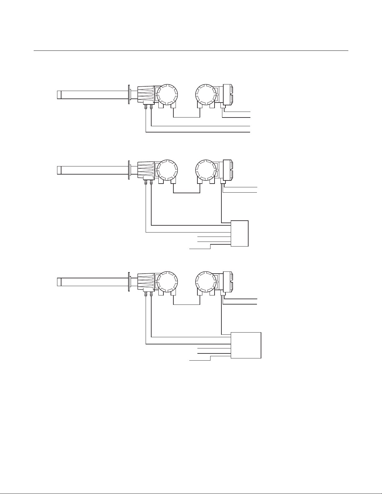
OXYMITTER4000
Instr. Air(Ref. Air)
Cal.Gas
LineVoltage
4-20mA
38890049
OXYMITTER4000
REMOTEELECTRONICS
ANDIMPS
WITH
OXYMITTER4000
REMOTEELECTRONICS
ANDSPS4001B
WITH
Cal.Gas1
Cal.Gas1
Cal.Gas2
Cal.Gas2
LineVoltage
LineVoltage
4-20mA
4-20mA
Instr. Air
Instr. Air
Reference Air
Reference Air
CalibrationGas
CalibrationGas
LogicI/O
LogicI/O
SPS
4001B
IMPS
4000
Figure 2. Installation Options Oxymitter 4000 with Remote
Electronics
Instruction Manual
IM-106-340, Rev. 4.2
July 2008
vi
Page 15

Instruction Manual
IM-106-340, Rev. 4.2
July 2008
Oxymitter 4000
CAN YOU USE THE QUICK START GUIDE?
Use this Quick Start Guide if...
1. Your system requires an Oxymitter 4000 with or without the SPS 4001B
OPTION. Installation options for the Oxymitter 4000 are shown in
Figure 1.
2. Your system does NOT require an IMPS 4000 OPTION installation.
3. Your system does NOT use a Remote Electronics as shown in Figure 2.
4. You are familiar with the installation requirements for the Oxymitter 4000
Oxygen Transmitter. You are familiar with the installation requirements
for the Oxymitter 4000 Oxygen Transmitter with a SPS 4001B.
If you cannot use the Quick Start Guide, turn to Section 3: Installation, in
this Instruction Manual.
vii
Page 16

Oxymitter 4000
Instruction Manual
IM-106-340, Rev. 4.2
July 2008
QUICK START GUIDE FOR OXYMITTER 4000 SYSTEMS
Before using the Quick Start Guide, please read "WHAT YOU NEED TO
KNOW BEFORE INSTALLING AND WIRING A ROSEMOUNT
ANALYTICAL OXYMITTER 4000 OXYGEN TRANSMITTER" on the
preceding page.
1. Install the Oxymitter 4000 in an appropriate location on the stack or
duct. Refer to "Selecting Location" in Section 3: Installation, for
information on selecting a location for the Oxymitter 4000.
2. If using an SPS 4001B, connect the calibration gasses to the
appropriate fittings on the SPS 4001B manifold.
3. Connect reference air to the Oxymitter 4000 or SPS 4001B, as
applicable.
4. If using an SPS 4001B, make the wiring connections as shown in the
SPS 4001B Single Probe Autocalibration Sequencer Instruction
Manual.
5. If NOT using an SPS 4001B, make the following wire connections as
shown in Figure 3: line voltage, 4-20 mA, and logic I/O.
6. Verify the Oxymitter 4000 switch configuration is as desired. Refer to
"Oxymitter 4000 Configuration", "SW1 Setting", and "SW2 Setting" all in
Section 2: Configuration of Oxymitter 4000 with Membrane Keypad, or
"Oxymitter 4000 Configuration", "SW1 Setting", and "SW2 Setting" all in
Section 4: Configuration of Oxymitter 4000 with LOI.
7. Apply power to the Oxymitter 4000; the cell heater will turn on. Allow
approximately one half hour for the cell to heat to operating
temperature. Once the ramp cycle has completed and the
Oxymitter 4000 is at normal operation, proceed with step 8 or 9.
8. If using an SPS 4001B, initiate a semi-automatic calibration.
9. If NOT using an SPS 4001B, perform a manual calibration. Refer to
"Calibration with Keypad" or "Calibration with LOI" both in Section 9:
Maintenance and Service, in this instruction manual.
viii
NOTE
If your system has a membrane keypad you can refer to the Quick Start Guide
on the following pages.
Page 17
Instruction Manual
AC L1
AC N
+
+
-
-
4-20
Terminal
Block
ACLine
VoltagePort
Signal
Port
LeftSideof
Oxymitter4000
4-20mA
Signal
38890100
AC Terminal
Cover
LineVoltage
(85to264VAC)
Ground
Lugs
LogicI/O
IM-106-340, Rev. 4.2
July 2008
Figure 3. Oxymitter 4000 without
SPS 4001B Wiring Diagram
Oxymitter 4000
QUICK REFERENCE GUIDE MANUAL CALIBRATION INSTRUCTIONS
Performing a Manual Calibration with a Membrane Keypad
1. Place the control loop in manual.
2. Press the CAL key. The CAL LED will light solid.
3. Apply the first calibration gas.
4. Press the CAL key. When the unit has taken the readings using the first
calibration gas, the CAL LED will flash continuously.
5. Remove the first calibration gas and apply the second calibration gas.
6. Push the CAL key. The CAL LED will light solid. When the unit has
taken the readings using the second calibration gas, the CAL LED will
flash a two-pattern flash or a three-pattern flash. A two-pattern flash
equals a valid calibration, three-pattern flash equals an invalid
calibration.
7. Remove the second calibration gas and cap off the calibration gas port.
8. Press the CAL key. The CAL LED will be lit solid as the unit purges.
When the purge is complete, the CAL LED will turn off.
9. If the calibration was valid, the DIAGNOSTIC ALARMS LEDs indicate
normal operation. If the new calibration values are not within the
parameters, the DIAGNOSTIC ALARMS LEDs will indicate an alarm.
10. Place the control loop in automatic.
ix
Page 18

Oxymitter 4000
PerformCalibration
2 3 1 1
Trim AnalogOutput
2 4
Toggle AnalogOutput Tracking
2 3 1 2
O UpperRangeValue
2
3 2 1
AnalogOutputLowerRangeValue
2 2
ViewO Value
2
1 1 1
3
View AnalogOutput
1 2 1
38890060
HART COMMUNICATOR FAST KEY SEQUENCES
Instruction Manual
IM-106-340, Rev. 4.2
July 2008
Technical Support Hotline:
For assistance with technical problems, please call the Customer Support
Center (CSC). The CSC is staffed 24 hours a day, 7 days a week.
Phone: 1-800-433-6076 1-440-914-1261
In addition to the CSC, you may also contact Field Watch. Field Watch
coordinates Emerson Process Management’s field service throughout the
U.S. and abroad.
Phone: 1-800-654-RSMT (1-800-654-7768)
Emerson Process Management may also be reached via the Internet through
e-mail and the World Wide Web:
e-mail: GAS.CSC@emersonprocess.com
World Wide Web: www.raihome.com
x
Page 19

Instruction Manual
IM-106-340, Rev. 4.2
July 2008
Oxymitter 4000
Section 1 Description and Specifications
Component Checklist . . . . . . . . . . . . . . . . . . . . . . . . . . . . .page 1-1
System Overview . . . . . . . . . . . . . . . . . . . . . . . . . . . . . . . . page 1-1
IMPS 4000 (Optional) . . . . . . . . . . . . . . . . . . . . . . . . . . . . . page 1-12
SPS 4001B (Optional) . . . . . . . . . . . . . . . . . . . . . . . . . . . . . page 1-12
Model 751 Remote Powered Loop LCD Display . . . . . . .page 1-13
Probe Options . . . . . . . . . . . . . . . . . . . . . . . . . . . . . . . . . . . page 1-13
Specifications . . . . . . . . . . . . . . . . . . . . . . . . . . . . . . . . . . . page 1-16
COMPONENT CHECKLIST
SYSTEM OVERVIEW
Scope
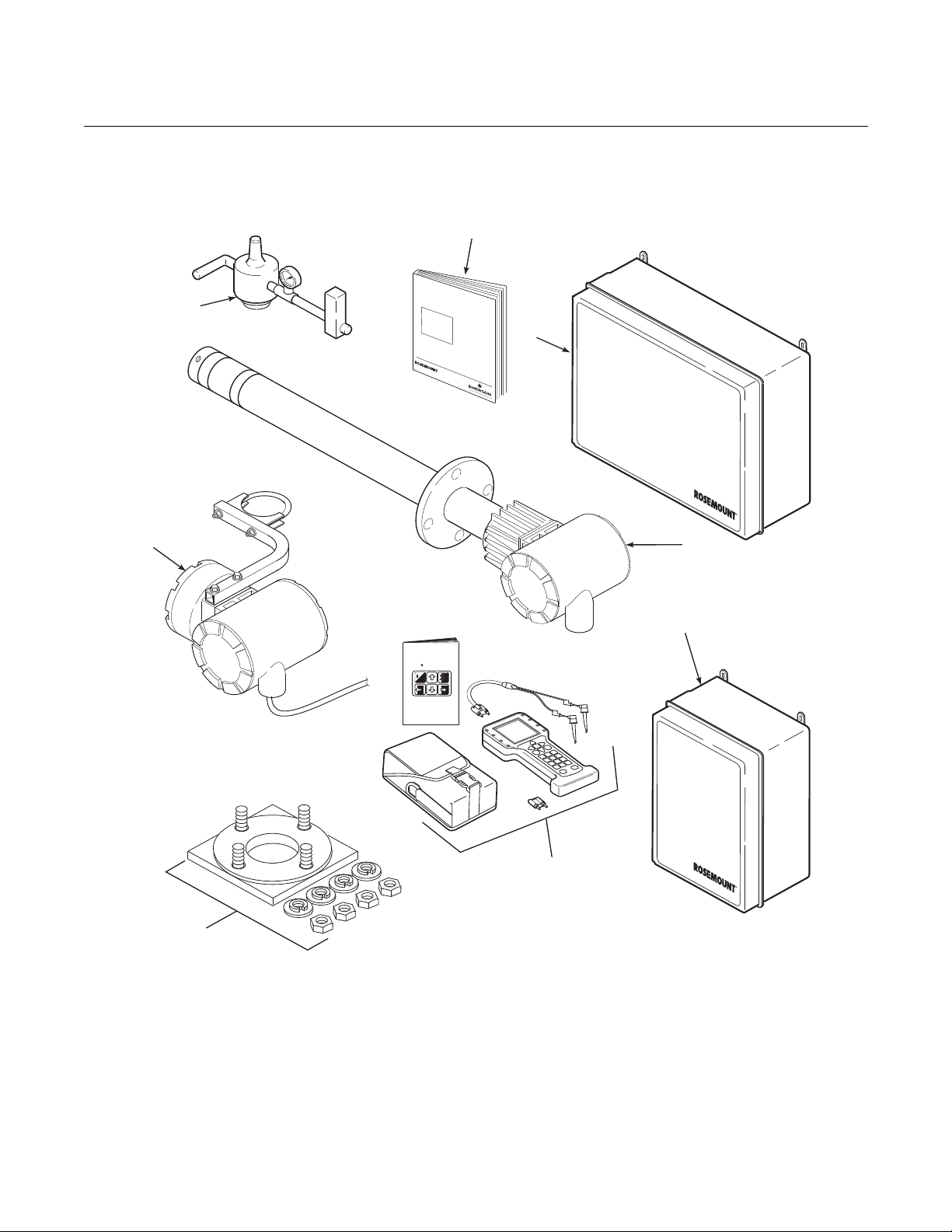
A typical Rosemount Analytical Oxymitter 4000 Oxygen Transmitter should
contain the items shown in Figure 1-1. Record the part number, serial number,
and order number for each component of your system in the table located on
the first page of this manual.
Also, use the product matrix in Table 1-1 at the end of this section to compare
your order number against your unit. The first part of the matrix defines the
model. The last part defines the various options and features of the Oxymitter
4000. Ensure the features and options specified by your order number are on
or included with the unit.
This Instruction Manual is designed to supply details needed to install, start
up, operate, and maintain the Oxymitter 4000. Signal conditioning electronics
outputs a 4-20 mA signal representing an O2 value and provides a membrane
keypad or fully functional Local Operator Interface (optional) for setup,
calibration, and diagnostics. This same information, plus additional details,
can be accessed with the HART Model 275/375 handheld communicator or
Asset Management Solutions (AMS) software.
http://www.raihome.com
Page 20
Oxymitter 4000
8
1
4
3
38890002
6
7
o
HART Communicator
MAN4275A00
English
5
2
Analytical
Analytical
An
a
l
y
t
i
c
al
OXYMITTER4000
HAZARDOUSAREA
OXYGENTRANSMITTER
InstructionManual
IM-106-340CRev.4.2
December2005
Figure 1-1. Typical System
Package
Instruction Manual
IM-106-340, Rev. 4.2
July 2008
1. Instruction Manual
2. IMPS 4000 Intelligent Multiprobe Test Gas Sequencer (Optional)
3. Oxymitter 4000 with Integral Electronics
4. SPS 4001B Single Probe Autocalibration Sequencer (Optional) (Shown with reference air option)
5. HART® 275/375 Communicator Package (Optional)
6. Adapter Plate with Mounting Hardware and Gasket
7. Remote Electronics and Cable (Optional)
8. Reference Air Set (used if SPS 4001B without reference air option or IMPS 4000 supplied)
1-2
Page 21

Instruction Manual
IM-106-340, Rev. 4.2
July 2008
Oxymitter 4000
System Description
The Oxymitter 4000 is designed to measure the net concentration of oxygen
in an industrial combustion processes process; i.e., the oxygen remaining
after all fuels have been oxidized. The probe is permanently positioned within
an exhaust duct or stack and performs its task without the use of a sampling
system.
The equipment measures oxygen percentage by reading the voltage
developed across a heated electrochemical cell, which consists of a small
yttria stabilized, zirconia disc. Both sides of the disc are coated with porous
metal electrodes. When operated at the proper temperature, the millivolt
output voltage of the cell is given by the following Nernst equation:
EMF = KT log10(P1/P2) + C
Where:
1. P2 is the partial pressure of the oxygen in the measured gas on one
side of the cell.
2. P1 is the partial pressure of the oxygen in the reference air on the
opposite side of the cell.
3. T is the absolute temperature.
4. C is the cell constant.
5. K is an arithmetic constant.
NOTE
For best results, use clean, dry, instrument air (20.95% oxygen) as the
reference air.
When the cell is at operating temperature and there are unequal oxygen
concentrations across the cell, oxygen ions will travel from the high oxygen
partial pressure side to the low oxygen partial pressure side of the cell. The
resulting logarithmic output voltage is approximately 50 mV per decade. The
output is proportional to the inverse logarithm of the oxygen concentration.
Therefore, the output signal increases as the oxygen concentration of the
sample gas decreases. This characteristic enables the Oxymitter 4000 to
provide exceptional sensitivity at low oxygen concentrations.
The Oxymitter 4000 measures net oxygen concentration in the presence of all
the products of combustion, including water vapor. Therefore, it may be
considered an analysis on a "wet" basis. In comparison with older methods,
such as the portable apparatus, which provides an analysis on a "dry" gas
basis, the "wet" analysis will, in general, indicate a lower percentage of
oxygen. The difference will be proportional to the water content of the
sampled gas stream.
1-3
Page 22

Oxymitter 4000
Instruction Manual
IM-106-340, Rev. 4.2
July 2008
System Configuration
Oxymitter 4000 units are available in seven length options, giving the user the
flexibility to use an in situ penetration appropriate to the size of the stack or
duct. The options on length are 18 in. (457 mm), 3 ft (0,91 m), 6 ft (1,83 m),
9 ft (2,7 m), 12 ft (3,66 m), 15 ft (4,57 m), and 18 ft (5,49 m).
The electronics control probe temperature and provide an isolated output,
4-20 mA, that is proportional to the measured oxygen concentration. The
power supply can accept voltages of 90-250 VAC and 48/62 Hz; therefore, no
setup procedures for power are required. The oxygen sensing cell is maintained at a constant temperature by modulating the duty cycle of the probe
heater portion of the electronics. The electronics accepts millivolt signals generated by the sensing cell and produces the outputs to be used by remotely
connected user devices. The output is an isolated 4-20 mA linearized current.
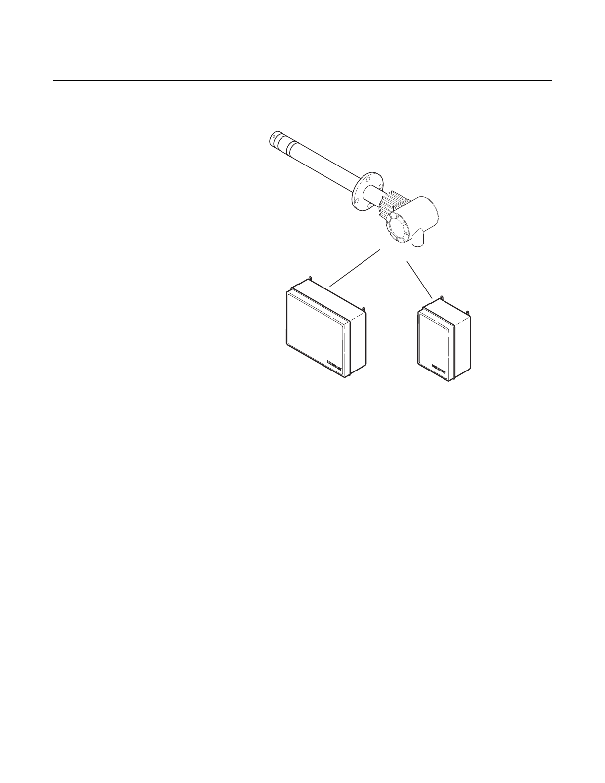
The Oxymitter 4000 transmitter is available with an integral or remote electronics package. Two calibration gas sequencers are available: the IMPS
4000 and the SPS 4001B (Figure 1-2).
Systems with multiprobe applications may employ an optional IMPS 4000
Intelligent Multiprobe Test Gas Sequencer. The IMPS 4000 provides automatic calibration gas sequencing for up to four Oxymitter 4000 units and
accommodates autocalibrations based on the CALIBRATION RECOMMENDED signal from the Oxymitter 4000, a timed interval set up in HART or
the IMPS 4000, or whenever a calibration request is initiated.
For systems with one or two Oxymitter 4000 units per combustion process, an
optional SPS 4001B Single Probe Autocalibration Sequencer can be used
with each Oxymitter 4000 to provide automatic calibration gas sequencing.
The SPS 4001B is fully enclosed in a NEMA cabinet suited for wall-mounting.
The sequencer performs autocalibrations based on the CALIBRATION RECOMMENDED signal from the Oxymitter 4000, a timed interval set up in HART,
or whenever a calibration request is initiated.
System Features
1. The CALIBRATION RECOMMENDED feature detects when the sensing
cell is likely out of limits. This may eliminate the need to calibrate on a
"time since last cal" basis.
2. The cell output voltage and sensitivity increase as the oxygen
concentration decreases.
1-4
Page 23
Instruction Manual
OXYMITTER4000
38890039
Analytical
Analytical
IMPS4000
(1to4Probes)
SPS4001B
(1Probe)
IM-106-340, Rev. 4.2
July 2008
Figure 1-2. Oxymitter 4000
AutoCalibration System Options
Oxymitter 4000
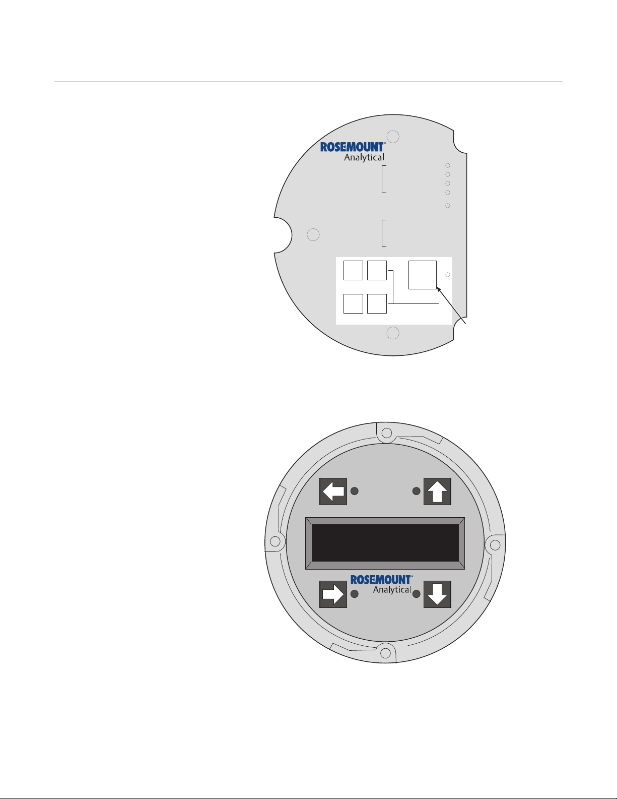
3. Membrane keypad, Figure 1-3, and HART communication are standard.
To use the HART capability, you must have either:
a. HART Model 275/375 Communicator.
b. Asset Management Solutions (AMS) software for the PC.
1-5
Page 24
Oxymitter 4000
DIAGNOSTIC
ALARMS
TEST
POINTS
HEATER T/C
HEATER
02CELL
CALIBRATION
CALIBRATIONRECOMMENDED
02CELL mV+
02CELL mvHEATER T/C+
HEATER T/C-
INC INC
DEC DEC
HIGH
GAS
LOW
GAS
CAL
TEST GAS+
PROCESS-
%02
MEMBRANE
KEYPAD
38890003
38890004
Figure 1-3. Membrane Keypad
Instruction Manual
IM-106-340, Rev. 4.2
July 2008
Figure 1-4. Local Operator
Interface (LOI)
1-6
4. An optional Local Operator Interface, Figure 1-4, allows continuous O2
display and full interface capability.
5. Field replaceable cell, heater, thermocouple, and diffusion element.
6. The Oxymitter 4000 is constructed of rugged 316 L stainless steel for all
wetted parts.
7. The electronics are adaptable for line voltages from 90-250 VAC;
therefore, no configuration is necessary.
Page 25

Instruction Manual
IM-106-340, Rev. 4.2
July 2008
Oxymitter 4000
8. The Oxymitter 4000 membrane keypad is available in five languages:
English
French
German
Italian
Spanish
9. An operator can calibrate and diagnostically troubleshoot the Oxymitter
4000 in one of four ways:
a. Membrane Keypad. The membrane keypad, housed within the right
side of the electronics housing, provides fault indication by way of
flashing LEDs. Calibration can be performed from the membrane
keypad.
b. LOI. The optional LOI takes the place of the membrane keypad and
allows local communication with the electronics. Refer to Section 6
for more information.
c. Optional HART Interface. The Oxymitter 4000's 4-20 mA output line
transmits an analog signal proportional to the oxygen level. The
HART output is superimposed on the 4-20 mA output line. This
information can be accessed through the following:
i. Rosemount Analytical Model 275/375 Handheld
Communicator - The handheld communicator requires
Device Description (DD) software specific to the
Oxymitter 4000. The DD software will be supplied with
many Model 275/375 units but can also be programmed
into existing units at most Emerson Process
Management service offices. See Section 7, HART/
AMS, for additional information.
ii. Personal Computer (PC) - The use of a personal
computer requires AMS software available from Emerson
Process Management.
iii. Selected Distributed Control Systems - The use of
distributed control systems requires input/output (I/O)
hardware and AMS software which permit HART
communications.
d. Optional IMPS 4000. The Programmable Logic Controller (PLC) in
the IMPS 4000 provides fault indications using flashing LEDs and
LCD display messages. Refer to the IMPS 4000 Intelligent
Multiprobe Test Gas Sequencer Instruction Manual for more
information.
1-7
Page 26
Oxymitter 4000
38890062
%
38890063
Analytical
Figure 1-5. Model 751 LCD
Display Panel
Figure 1-6. OxyBalance Display
Displaying Outputs
Instruction Manual
IM-106-340, Rev. 4.2
July 2008
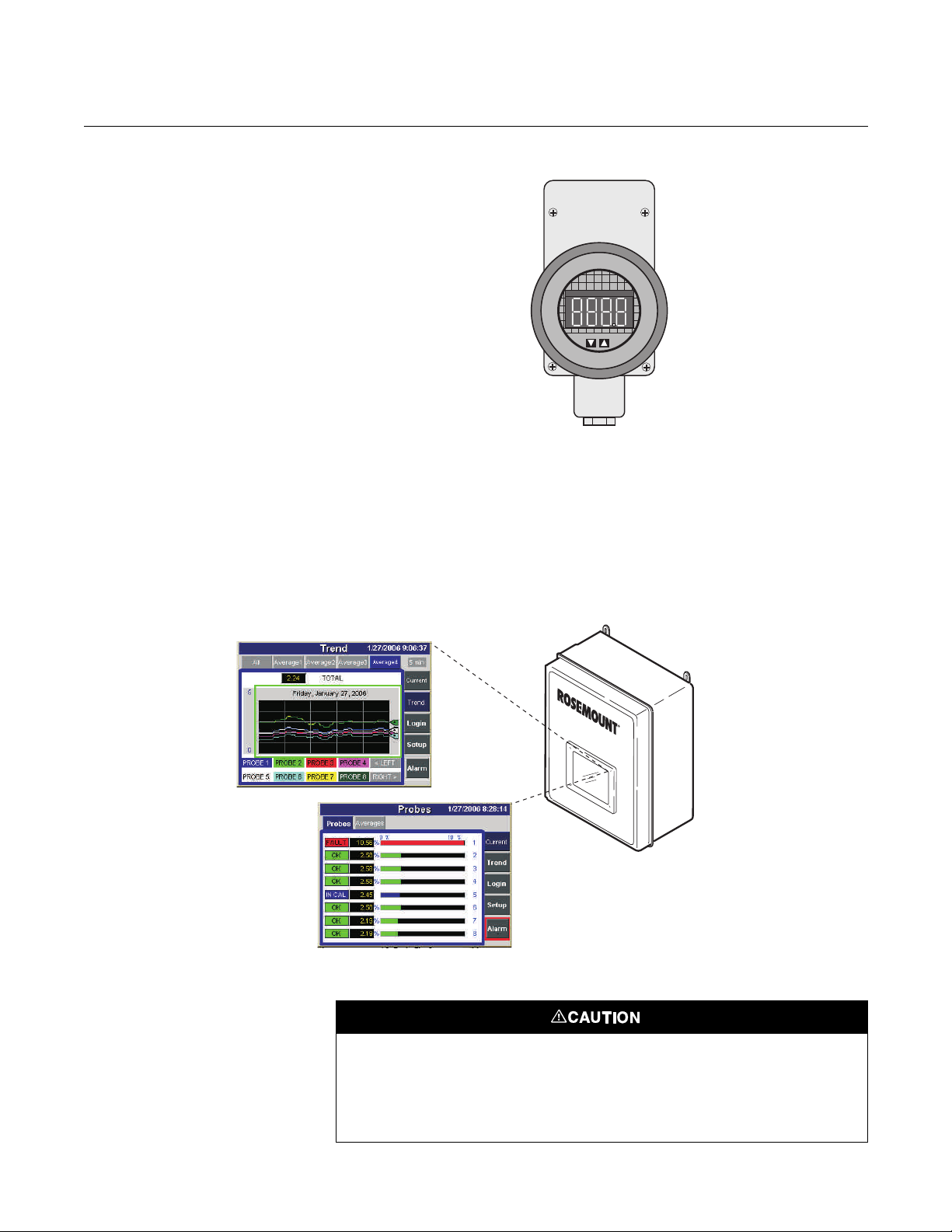
10. The optional Rosemount Analytical 751 remote-mounted LCD display
panel shown in Figure 1-5 is loop-driven by the 4-20 mA output signal
representing the O2 percentage.
11. Optional OxyBalance Display and Averaging System. Reviews up to
eight 4-20 mA signals from individual probes. Trends individual outputs,
calculates four programmable averages as additional 4-20 mA outputs.
Handling the Oxymitter 4000
1-8
It is important that printed circuit boards and integrated circuits are handled only when
adequate antistatic precautions have been taken to prevent possible equipment damage.
The Oxymitter 4000 is designed for industrial applications. Treat each component of the
system with care to avoid physical damage. Some probe components are made from
ceramics, which are susceptible to shock when mishandled.
Page 27
Instruction Manual
38890005
4-20mA Output
(TwistedPairs)
2CalibrationGasLines
byCustomer
[ ( )max]300ft 90m
HART
Model275/375
Handheld
Interface
Terminationin
ControlRoom
AssetManagementSolutions
LineVoltage
Hazardous Area
Oxymitter4000
withIntegralElectronics
IM-106-340, Rev. 4.2
July 2008
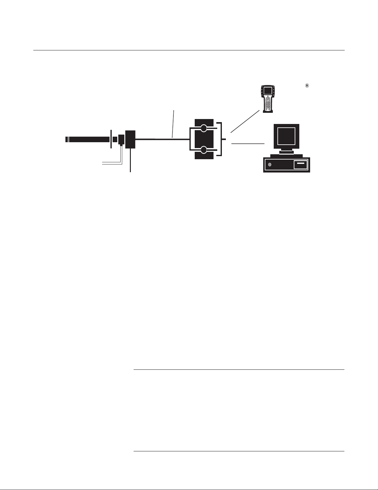
Figure 1-7. Oxymitter 4000
HART Communications and
AMS Application
Oxymitter 4000
System Considerations
Prior to installing your Oxymitter 4000, make sure you have all the
components necessary to make the system installation. Ensure all the
components are properly integrated to make the system functional.
After verifying that you have all the components, select mounting locations
and determine how each component will be placed in terms of available line
voltage, ambient temperatures, environmental considerations, convenience,
and serviceability.
Figure 1-7 shows a typical system wiring.
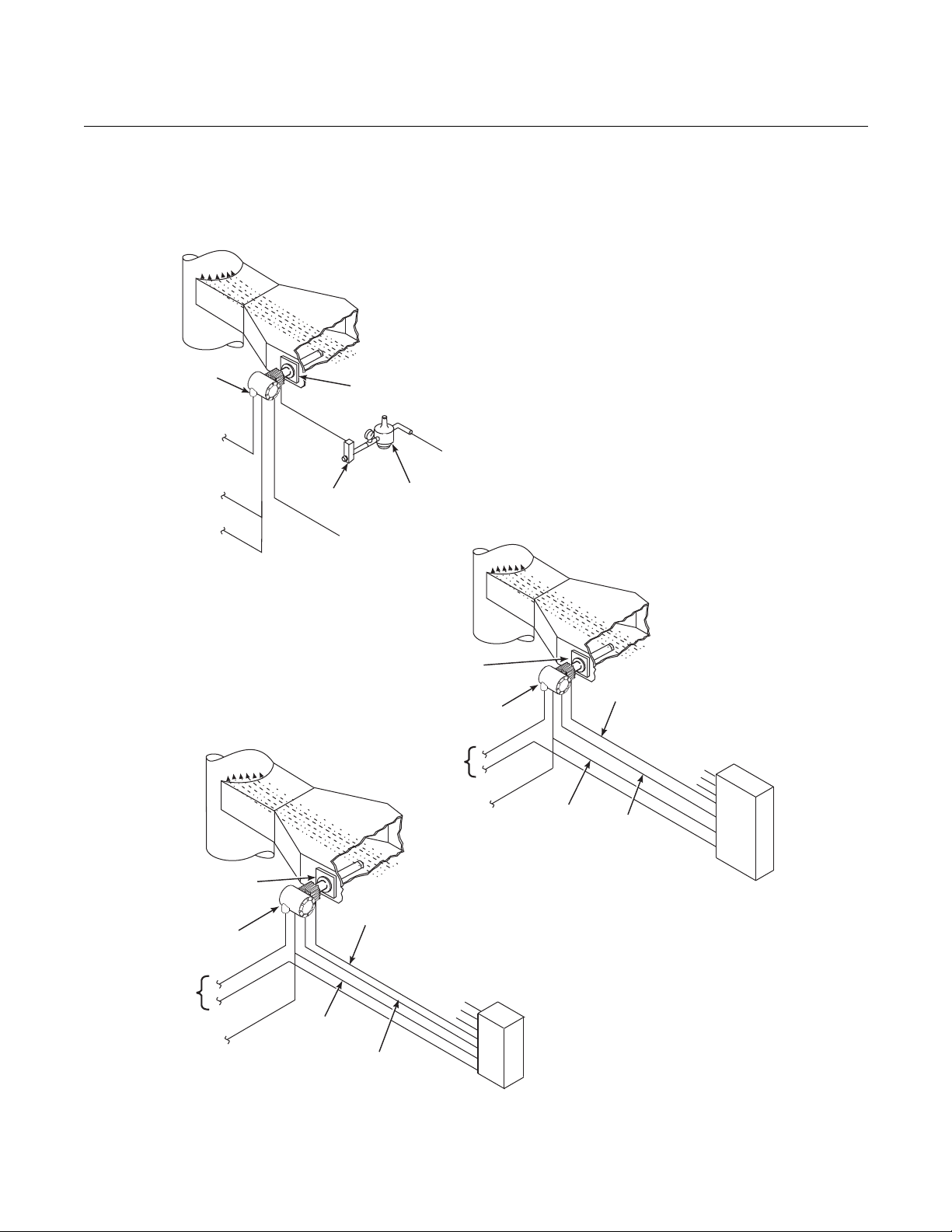
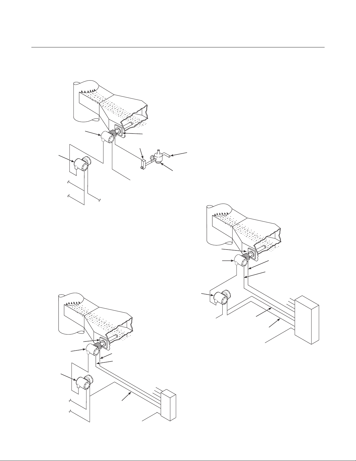
A typical system installation for an Oxymitter 4000 with integral electronics is
shown in Figure 1-8. A typical system installation for an Oxymitter 4000 with
remote electronics is shown in Figure 1-9.
A source of instrument air is optional at the Oxymitter 4000 for reference
air use. Since the unit is equipped with an in place calibration feature,
provisions can be made to permanently connect calibration gas bottles to the
Oxymitter 4000.
If the calibration gas bottles will be permanently connected, a check valve is
required next to the calibration fittings on the integral electronics.
This check valve is to prevent breathing of the calibration gas line and
subsequent flue gas condensation and corrosion. The check valve is in
addition to the stop valve in the calibration gas kit or the solenoid valves in the
IMPS 4000 or SPS 4001B.
NOTE:
The electronics is rated NEMA 4X (IP66) and is capable of operation at
temperatures up to 185°F (85°C).
The optional LOI is also rated for operation at temperatures up to 185°F
(85°C). The infrared keypad functionality will degr ade at temperatures above
158°F (70°C).
Retain the packaging in which the Oxymitter 4000 arrived from the factory in
case any components are to be shipped to another site. This packaging has
been designed to protect the product.
1-9
Page 28
Oxymitter 4000
Oxymitter
4000
SPS 4001B
Reference
Air
Logic I/O
Calibration Gas
Adapter Plate
Stack
Duct
Gases
Calibration Gas 1
Calibration Gas 2
Inst. Air Supply
Line Voltage
4to20mA
Signal
Duct
Stack
Gases
Calibration
Gas
Adapter
Plate
Line
Voltage
Logic I/O
Instrument
Air Supply
(Reference Air)
Pressure
Regulator
Flowmeter
STANDARD
Oxymitter
4000
4to20mA
Signal
Oxymitter
4000
IMPS 4000* MULTIPROBE
AUTOCALIBRATION
OPTION
IMPS 4000
Reference
Air
Logic I/O
Calibration
Gas
Adapter
Plate
Stack
Duct
Gases
Calibration Gas 1
Calibration Gas 2
Inst. Air Supply
Line
Voltage
4to20mA
Signal
SPS 4001B* SINGLE PROBE
AUTOCALIBRATION OPTION
(WITH REFERENCE AIR OPTION)
38890047
Figure 1-8. Typical System
Installation - Oxymitter 4000 with
Integral Electronics
Instruction Manual
IM-106-340, Rev. 4.2
July 2008
1-10
Page 29
Instruction Manual
38890006
Duct
Stack
Gases
Calibration
Gas
Adapter Plate
Line
Voltage
Logic I/O
Instrument
Air Supply
(Reference Air)
Pressure
Regulator
Flowmeter
STANDARD
Oxymitter 4000
Oxymitter 4000
4to20mA
Signal
IMPS 4000
Reference Air
Calibration Gas
Adapter Plate
Stack
Duct
Gases
Calibration Gas 1
Calibration Gas 2
Inst. Air Supply
Line Voltage
4to20mA
Signal
Remote
Electronics
Remote
Electronics
Logic I/O
Line Voltage
*Note: TheIMPS4000orSPS4001Bmust
beinstalledinanon-hazardous,
explosive-freeenvironment.
SPS 4001B* SINGLE PROBE
AUTOCALIBRATION OPTION
(WITH REFERENCE AIR OPTION)
Oxymitter
4000
SPS 4001B
Logic I/O
Calibration Gas
Adapter Plate
Stack
Duct
Gases
Calibration Gas 1
Calibration Gas 2
Inst.
Air Supply
Remote
Electronics
Line Voltage
Line Voltage
Reference Air
4to20mA
Signal
IMPS 4000* MULTIPROBE
AUTOCALIBRATION
OPTION
IM-106-340, Rev. 4.2
July 2008
Figure 1-9. Typical System
Installation - Oxymitter 4000 with
Remote Electronics
Oxymitter 4000
1-11
Page 30

Oxymitter 4000
Instruction Manual
IM-106-340, Rev. 4.2
July 2008
IMPS 4000 (OPTIONAL)
SPS 4001B (OPTIONAL)
Mounting
Information on the IMPS 4000 is available in the IMPS 4000 Intelligent
Multiprobe Test Gas Sequencer Instruction Manual.
The SPS 4001B Single Probe Autocalibration Sequencer provides the
capability of performing automatic, timed or on demand, calibrations of a
single Oxymitter 4000 without sending a technician to the installation site.
The SPS 4001B is fully enclosed in a NEMA cabinet suited for wall-mounting.
This cabinet provides added protection against dust and minor impacts. The
SPS 4001B consists of a manifold and a calibration gas flowmeter. The manifold provides electrical feedthroughs and calibration gas ports to route power
and signal connections and calibration gases to and from the sequencer. In
addition, the manifold houses two calibration gas solenoids that sequence the
gases to the Oxymitter 4000, a pressure switch that detects low calibration
gas pressure, and two PC boards. A terminal strip housed within the terminal
cover provides convenient access for all user connections.
Components optional to the SPS 4001B include a reference air flowmeter and
pressure regulator. The reference air flowmeter indicates the flow rate of
reference air continuously flowing to the Oxymitter 4000. The reference air
pressure regulator ensures the instrument air (reference air) flowing to the
Oxymitter 4000 is at a constant pressure [20 psi (138 kPa)]. The regulator
also has a filter to remove particulates in the reference air and a drain valve to
bleed the moisture that collects in the filter bowl.
Brass fittings and Teflon tubing are standard. Stainless steel fittings and
tubing are optional. Also, disposable calibration gas bottles are available as
an option or can be purchased through a local supplier.
Operation
The SPS 4001B works in conjunction with the Oxymitter 4000's CALIBRATION RECOMMENDED feature to perform an autocalibration. This feature
automatically performs a gasless calibration check every hour on the Oxymitter 4000. If a calibration is recommended and its contact output signal is set
for "handshaking" with the sequencer, the Oxymitter 4000 sends a signal to
the sequencer. The sequencer automatically performs a calibration upon
receiving the signal. Thus, no human interface is required for the automatic
calibration to take place. For further SPS 4001B information, refer to the SPS
4001B Single Probe Autocalibration Sequencer Instruction Manual.
1-12
Page 31

Instruction Manual
38890064
%
38890065
IM-106-340, Rev. 4.2
July 2008
Oxymitter 4000
MODEL 751 REMOTE POWERED LOOP LCD DISPLAY
Figure 1-10. Model 751 Remote
Powered Loop LCD Display
PROBE OPTIONS
The display (Figure 1-10) provides a simple, economical means to obtain
accurate, reliable, and remote indication of important process variables. This
display operates on the 4-20 mA line from the Oxymitter 4000. Refer to Model
751 remote powered loop LCD manual for calibration and wiring.
Diffusion Elements
Figure 1-11. Ceramic Diffusion
Assembly
Ceramic Diffusion Assembly
The ceramic diffusion assembly, Figure 1-11, is the traditional design for the
probe. Used for over 25 years, the ceramic diffusion assembly provides a
greater filter surface area. This element is also available with a flame arrestor,
and with a dust seal for use with an abrasive shield.
1-13
Page 32

Oxymitter 4000
38890066
38890067
Figure 1-12. Snubber Diffusion
Assembly
Instruction Manual
IM-106-340, Rev. 4.2
July 2008
Snubber Diffusion Assembly
The snubber diffusion assembly, Figure 1-12, is satisfactory for most
applications. This element is also available with a flame arrestor, and with a
dust seal for use with an abrasive shield.
Figure 1-13. Hastelloy Cup-Type
Diffusion Assembly
Cup-Type Diffusion Assembly
The cup-type diffusion assembly, Figure 1-13, is typically used in high
temperature applications where frequent diffusion element plugging is a
problem. It is available with either a 10 or 40 micron, sintered, Hastelloy
element.
This element is also available with a dust seal for use with an abrasive shield.
Abrasive Shield Assembly
1-14
The abrasive shield assembly, Figure 1-14, is a stainless steel tube that
surrounds the probe assembly. The shield protects against particle abrasion,
provides a guide for ease of insertion, and acts as a position support,
especially for longer probes. The abrasive shield assembly uses a modified
diffuser and vee deflector assembly, fitted with dual dust seal packing.
Page 33

Instruction Manual
VIEW A
VIEWB
A
B
A
B
15
o
6.00
.45min
90
o
3.584
3.554
22.5
o
Diaona7.50DiaB.C.(ref)
.745
.755
0.75thru4pls,
eqspon4.75B.C.
38890068
IM-106-340, Rev. 4.2
July 2008
Figure 1-14. Abrasive Shield
Assembly
Oxymitter 4000
NOTE
In highly abrasive applications, rotate the shield 90 degrees at normal
service intervals to present a new wear surface to the abrasive flow stream.
1-15
Page 34

Oxymitter 4000
APPROVED
US
C
SPECIFICATIONS
Instruction Manual
IM-106-340, Rev. 4.2
July 2008
Oxymitter Specifications
O2 Range
Standard 0 to 10% O2, 0 to 25% O2, 0 to 40% O2 (via HART)
Accuracy ±0.75% of reading or 0.05% O2, whichever is greater
System Response to Calibration
Gas
Temperature Limits
Process 32° to 1300°F (0° to 704°C) up to 2400°F (1300°C)
Electronics Housing -40° to 158°F (-40° to 70°C) amb ient
Electronics Package -40° to 185°F (-40° to 85°C) [Operating temperature
Local Operator Interface -40° to 158°F (-40° to 70° C), [above 158°F (70°C) the
Probe Lengths 18 in. (457 mm) 12 ft (3,66 m)
Mounting and Mounting Position Vertical or horizontal;
Materials
Probe Wetted or welded parts - 316L stainless steel (SS)
Electronics Enclosure Low-copper aluminum
Calibration Manual, semi-automatic, or automatic
Calibration Gas Mixtures
Recommended
Calibration Gas Flow 2.5 l/min (5 scfh)
Reference Air 1 l/min (2 scfh), clean, dry, instrument-quality air
Electronics NEMA 4X, IP66 with fitting and pipe on reference
Electric Noise EN 61326-1, Class A
Certifications General Purpose
Initial – less than 3 seconds, T90 – less than 8
seconds
with optional accessories
of electronics inside of instrument housing, as
measured by a HART communicator, Rosemount
Analytical Asset Management Solutions software.]
infrared keypad will cease to function, but the
Oxymitter 4000 will continue to operate properly.]
3 ft (0,91 m) 15 ft (4,57 m)
6 ft (1,83 m) 18 ft (5,49 m)
9 ft (2,74 m)
a spool piece, (P/N 3D39761G02), is available to
offset transmitter housing from hot ductwork.
Non-wetted parts - 304 SS, low-copper aluminum
0.4% O2, Balance N
8% O2, Balance N
(20.95% O2), regulated to 34 kPa (5 psi)
exhaust port to clear dry atmosphere
2
2
Line Voltage 90-250 VAC, 48/62 Hz. No configuration necessary.
Table continued on next page
1-16
3/4 in. -14 NPT conduit port
Page 35

Instruction Manual
IM-106-340, Rev. 4.2
July 2008
Oxymitter 4000
Oxymitter Specifications
Signals
Analog Output/HART 4-20 mA isolated from power supply, 950 ohms
maximum load
Logic I/O Two-terminal logic contact configurable as either an
alarm output or as a bi-directional calibration
handshake signal to IMPS 4000 or SPS 4001B,
self-powered (+5 V) in series with 340 ohms
Conduit ports — 3/4 in.-14 NPT (for analog output and
logic I/O signal lines)
Power Requirements:
Probe Heater 175 W nominal
Electronics 10 W nominal
Maximum 500 W
1-17
Page 36

Oxymitter 4000
Table 1-1. Product Matrix
OXT4A Oxymitter 4000 In Situ Oxygen Transmitter
Oxygen Transmitter - Instruction Book
Code Sensing Probe Type
1 ANSI (N. American Std.) Probe with Ceramic Diffuser
2 ANSI Probe with Flame Arrestor and Ceramic Diffuser
3 ANSI Probe with Snubber Diffuser
4 DIN (European Std.) Probe with Ceramic Diffuser
5 DIN Probe with Flame Arrestor and Snubber Diffuser
6 DIN Probe with Snubber Diffuser
Code Probe Assembly
0 18 in. (457 mm) Probe
1 18 in. (457 mm) Probe with Abrasive Shield
2 3 ft (0,91 m) Probe
3 3 ft (0,91 m) Probe with Abrasive Shield
4 6 ft (1,83 m) Probe
5 6 ft (1,83 m) Probe with Abrasive Shield
6 9 ft (2,74 m) Probe
7 9 ft (2,74 m) Probe with Abrasive Shield
8 12 ft (3,66 m) Probe
9 12 ft (3,66 m) Probe with Abrasive Shield
A 15 ft (4,57 m) Probe with Abrasive Shield
B 18 ft (5,49 m) Probe with Abrasive Shield
Code Mounting Hardware- Stack Side
0 No Mounting Hardware ("0" must be chosen under "Mounting Hardware - Probe Side" below)
1 New Installation - Square weld plate with studs
2 Mounting to Model 218 Mounting Plate (with Model 218 Shield Removed)
3 Mounting to Existing Model 218 Support Shield
4 Mounting to Other Mounting
5 Mounting to Model 132 Adapter Plate
Code Mounting Hardware- Probe Side
0 No Mounting Hardware
1 Probe Only (ANSI) (N. American Std.)
2 New Bypass or New Abrasive Shield (ANSI)
4 Probe Only (DIN)
5 New Bypass or New Abrasive Shield (DIN)
Code Electronic Housing & Filtered Customer Termination - NEMA 4X, IP66
12 HART Integral Electronics, Transient Protected Filtered Termination, ATEX
Certification
14 Remote Electronics with Transient Protected Filtered Termination
(requires cable)
OXT4C 3 3 1 1 12 Example
(1)
(1)
(1)
(1)
(1)
(1)
(1)
(2)
Instruction Manual
IM-106-340, Rev. 4.2
July 2008
1-18
Page 37

Instruction Manual
IM-106-340, Rev. 4.2
July 2008
Cont’d
Code Operator Interface
1 HART with Membrane Keypad - blind cover
2 HART with Membrane Keypad - window cover
3 HART with Local Operation Interface, window cover, English only
Code Language
1 English
2 German
3 French
4 Spanish
5 Italian
Oxymitter 4000
(3)
Code Termination Filtering
00 Specified as part of Electronic Housing
Code Calibration Accessories
00 No Hardware
01 Calibration Gas Flowmeter and Reference Air Set
02 Intelligent Multiprobe Sequencer (Refer to Table 1-3)
Code Electronics to Probe Cable
00 No Cable
10 20 ft (6 m) Cable
11 40 ft (12 m) Cable
12 60 ft (18 m) Cable
13 80 ft (24 m) Cable
14 100 ft (30 m) Cable
15 150 ft (45 m) Cable
16 200 ft (61 m) Cable
Cont’d 1 3 00 01 00 Example
NOTES:
(1)
Recommended uses: High velocity particulates in flue stream, installation within 11.5 ft (3,5 m) of soot blowers or heavy salt cake buildup. Applications:
Pulverized coal, recovery boilers, lime kiln.
(2)
Where possible, specify ANSI or DIN designation; otherwise, provide details of the existing mounting plate as follows:
Plate with studs Bolt circle diameter, number, and arrangement of studs; stud thread; and stud height above mounting plate.
Plate without studs Bolt circle diameter, number, and arrangement of holes; thread; and depth of stud mounting plate with accessories.
1-19
Page 38

Oxymitter 4000
Table 1-2. Calibration
Components
Table 1-3. Intelligent Multiprobe
Test Gas Sequencer Versions
Instruction Manual
IM-106-340, Rev. 4.2
July 2008
Part Number Description
1A99119G01 Two disposable calibration gas bottles - 0.4% and 8% O2, balance
1A99119G02 Two flow regulators for calibration gas bottles
1A99119G03 Bottle rack
Notes:
*Calibration gas bottles cannot be shipped via airfreight.
When the bottles are used with CALIBRATION RECOMMENDED features, the bottles should provide
2 to 3 years of calibrations in normal service.
Part Number Description Number of Oxymitters
3D39695G01 IMPS 1
3D39695G02 IMPS 2
3D39695G03 IMPS 3
3D39695G04 IMPS 4
3D39695G05 IMPS w/115 V Heater 1
3D39695G06 IMPS w/115 V Heater 2
3D39695G07 IMPS w/115 V Heater 3
3D39695G08 IMPS w/115 V Heater 4
3D39695G09 IMPS w/220V Heater 1
3D39695G10 IMPS w/220V Heater 2
3D39695G11 IMPS w/220V Heater 3
3D39695G12 IMPS w/220V Heater 4
nitrogen - 550 liters each*
1-20
Page 39

Instruction Manual
IM-106-340, Rev. 4.2
July 2008
Oxymitter 4000
Section 2 Configuration of Oxymitter 4000
with Membrane Keypad
Verify Installation . . . . . . . . . . . . . . . . . . . . . . . . . . . . . . . . page 2-1
Logic I/O . . . . . . . . . . . . . . . . . . . . . . . . . . . . . . . . . . . . . . . page 2-5
VERIFY INSTALLATION
Install all protective equipment covers and safety ground leads before equipment startup.
Failure to install covers and ground leads could result in serious injury or death.
Mechanical Installation
Terminal Block Wiring
Ensure the Oxymitter 4000 is installed correctly. See Section 3: Installation.
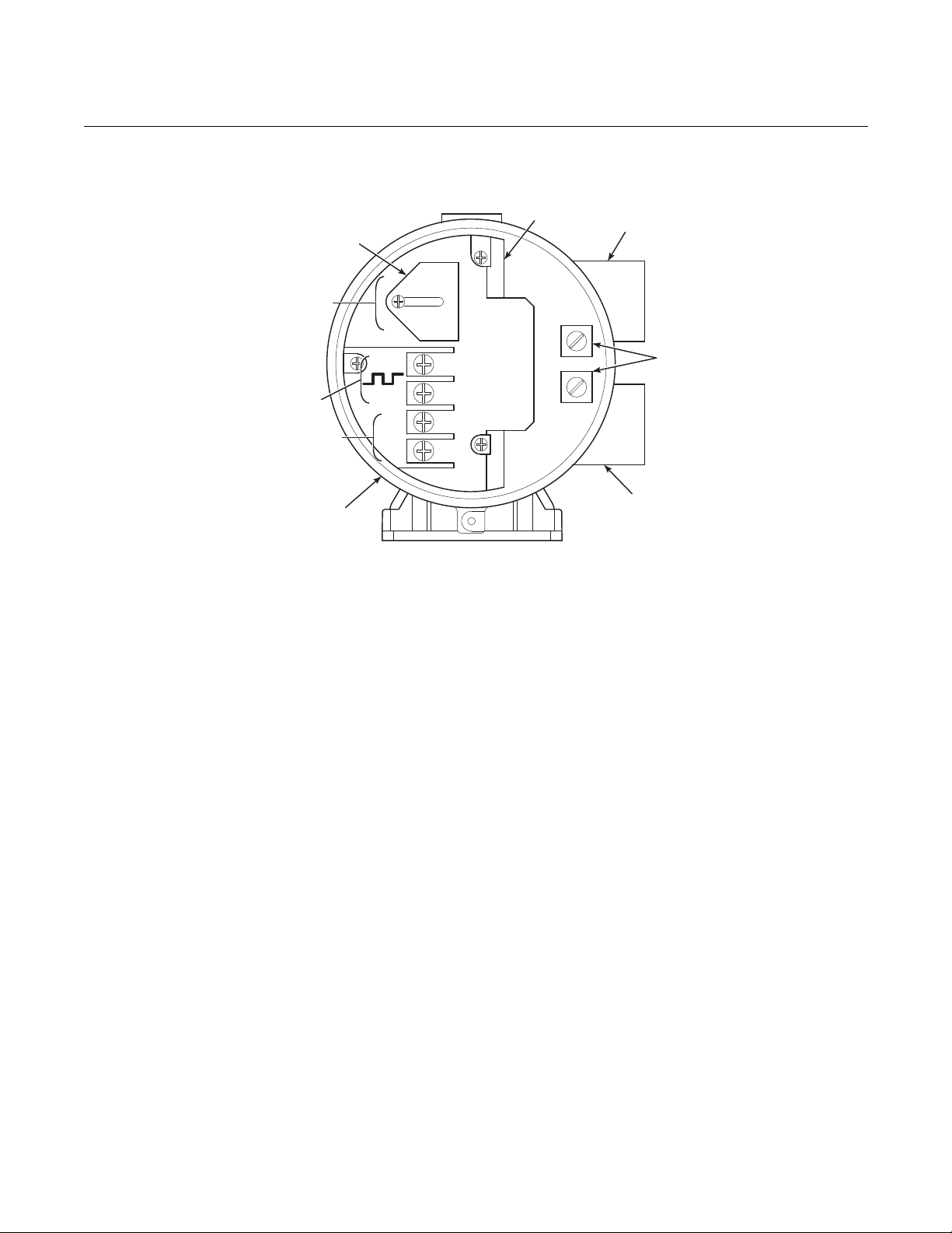
1. Remove cover (27) to expose terminal block (25).
2. Check the terminal block wiring (Figure 2-1). Be sure the power,
4-20 mA signal, and the logic outputs are properly connected and
secure. To avoid a shock hazard, the power terminal cover must be
installed. For units with remote electronics, check the terminal block
wiring at the probe and at the remote electronics unit.
3. Install housing cover (27, Figure 9-3 or Figure 9-4) on terminal block
(25).
http://www.raihome.com
Page 40

Oxymitter 4000
38890009
ACL1
ACN
+
+
-
-
4-20
500 VA
SERIAL NO.
TAG NO.
OXYMITTER 4000
WATTS:VOLTS:
FUSE:LINEOUTPUT:
RosemountAnalyticalInc.
Solon,OH44139
85-264 VAC 48-62 Hz
TM
800-433-6076
4-20 mA
R
5 Amps
TM
HART
SMART FAMILY
DIAGNOSTIC
ALARMS
TEST
POINTS
HEATERT/C
HEATER
02CELL
CALIBRATION
CALIBRATIONRECOMMENDED
02CELLmV+
02CELLmvHEATERT/C+
HEATERT/C-
INC INC
DEC DEC
HIGH
GAS
LOW
GAS
CAL
TESTGAS+
PROCESS-
%02
SW2
TP1
J1
TP2
TP3
RED
YEL
GRN
ORG
TP4
TP5
TP6
ON
4-20mA
Signal
LogicI/O
GroundLugs
Terminal
Block
Oxymitter4000
Electronics
Housing
Figure 2-1. Electronics Housing
Terminals and Membrane
Keypad
Instruction Manual
IM-106-340, Rev. 4.2
July 2008
Oxymitter 4000 Configuration
2-2
Located on the microprocessor board, the top board, are two switches that
configure outputs for the Oxymitter 4000 (Figure 2-2). SW1 determines if the
4-20 mA signal is internally or externally powered. SW2 determines:
1. Oxymitter 4000 status, HART or LOCAL.
2. Oxygen range, 0 to 10% O2 or 0 to 25% O2. (0 to 40% O2 is also
configurable only through HART/AMS.)
3. The 4-20 mA signal, at fault or power up, 3.5 mA or 21.6 mA.
Remove power from the Oxymitter 4000 before changing defaults. If defaults are changed
under power, damage to the electronics package may occur.
SW1 Setting
The two settings are internally or externally powering the 4-20 mA signal. The
factory setting is for the 4-20 mA signal to be internally powered.
Page 41

Instruction Manual
IM-106-340, Rev. 4.2
July 2008
Oxymitter 4000
SW2 Setting
The factory sets this switch as follows:
1. Position 1 is HART/LOCAL. This switch setting controls the configuration of the Oxymitter 4000. The defaults cannot be changed via
HART/AMS unless the switch is in the HART position. Placing SW2,
position 1 in the LOCAL position forces the O2 range to the setting of
position 2. The position 1 switch must be placed in the LOCAL position
or changes in SW2, position 2 will have no effect.
2. Position 2 determines the O2 range. This can be set to either 0 to 10%
O2 or 0 to 25% O2. The factory setting is 0 to 10% O2. If necessary, the
O2 range can be configured from 0 to 40% O2. To select values within
this range, set SW2, position 1 to HART and then enter the range via
HART/AMS. Do not change SW2, position 1 to LOCAL unless you want
to operate in the range specified by SW2, position 2.
Typically, the probe's sensing cell, in direct contact with the process gases, is heated to
approximately 1357°F (736°C). The external temperat ure of the probe body may exceed
842°F (450°C). If operating conditions also contain high oxygen levels and combustible
gases, the Oxymitter 4000 may self-ignite.
3. Position 3 determines the output at startup or at an alarm. The settings
are 3.5 mA or 21.6 mA. The factory setting is 3.5 mA. At startup, the
current at the analog output is 3.5 mA or 21.6 mA.
4. Position 4 can be used to set the heater for 115 or 220 VAC operation.
This switch is functional only when the software is set for manual
voltage selection (Auto Tune = No). Otherwise, the internal electronics
auto detect the input line voltage and sets the heater voltage
accordingly (Auto Tune = Yes).
2-3
Page 42

Oxymitter 4000
38890010
DIAGNOSTIC
ALARMS
TEST
POINTS
HEATER T/C
HEATER
O2 CELL
CALIBRATION
CALIBRATION RECOMMENDED
O2 CELL mV +
O2 CELL mV -
HEATER T/C +
HEATER T/C -
INC INC
DEC DEC
HIGH
GAS
LOW
GAS
CAL
TEST GAS +
PROCESS -
% O2
SW2
SW1
TP1
J1
TP2
TP3
RED
YEL
GRN
ORG
TP4
TP5
TP6
ON
4-20mA
isinternally
powered(Default)
4-20mA requires
externalpower
HART
0to10%O
2
3.5mA
220V 115V
0to25%O
2
Local
21.6mA
Default
position
(Ex-factory)
3.5mA/21.6mA:
0to25%O :
2
0to10%O /
2
Local:
HART:
O RangesetbyHART/AMS
(From0to40%O )
O RangesetbyPos2
O Range
Whenalarmexists,oronpowerup,outputcurrentgoestothis
value
2
2
2
2
1
2
3
4
ON
OFF
Note:
The115Voptionatswitch
SW2position4isactiveonly
whentheheatervoltage
optionissettomanualinthe
software
(autotune=no).
Figure 2-2. Defaults - Oxymitter
4000 with Membrane Keypad
Instruction Manual
IM-106-340, Rev. 4.2
July 2008
Read O2 Concentration
Once the cell is up to operating temperature, the O2 percentage can be read:
1. Access TP5 and TP6 next to the membrane keypad. Attach a
multimeter across TP5 and TP6. The calibration and process gases can
now be monitored. Pressing the INC or DEC once will cause the output
to switch from the process gas to the calibration gas. Pressing INC or
DEC a second time will increase or decrease the calibration gas
parameter. If the keys have been inactive for one minute, the output
reverts to the process gas. If the keys have been inactive for one
minute, the output reverts to the process gas.
2-4
Page 43

Instruction Manual
IM-106-340, Rev. 4.2
July 2008
Oxymitter 4000
When a calibration has been initiated, the value at TP5 and TP6 is the
% O2 seen by the cell.
Oxygen levels, as seen on the multimeter, are:
8.0% O2 = 8.0 VDC
0.4% O2 = 0.4 VDC
2. HART/AMS.
3. Model 751. The loop-driven LCD display.
LOGIC I/O
Table 2-1. Logic I/O
Configuration (as set at
HART/AMS or LOI)
This two-terminal logic contact can be configured either as a solid-state
relay-activated alarm or as a bi-directional calibration handshake signal to an
IMPS 4000 or SPS 4001B. The configuration of this signal depends on the
setting of the LOGIC I/O PIN MODE via HART/AMS or LOI. The ten different
modes available are explained in Table 2-1.
Mode Configuration
0 The unit is not configured for any alarm condition.
1 The unit is configured for a Unit Alarm.
2 The unit is configured for Low O2.
3 The unit is configured for both a Unit Alarm and Low O2.
4 The unit is configured for a High AC Impedance/CALIBRATION
RECOMMENDED.
5* The unit is configured for both a Unit Alarm and a High AC
Impedance/CALIBRATION RECOMMENDED.
6 The unit is configured for both a Low O2 and High AC Impedance/CALIBRATION
RECOMMENDED.
7 The unit is configured for a Unit Alarm, a Low O2, and a High AC
Impedance/CALIBRATION RECOMMENDED.
8** The unit is configured for a calibration handshake with IMPS 4000 or SPS 4001B.
CALIBRATION RECOMMENDED will initiate the calibration cycle.
9 The unit is configured for a calibration handshake. CALIBRATION
RECOMMENDED will not initiate the calibration cycle with the IMPS 4000 or
SPS 4001B.
*The default condition for an Oxymitter 4000 without an IMPS 4000 or SPS 4001B.
**The default condition for an Oxymitter 4000 with an IMPS 4000 or SPS 4001B.
Alarm
When configured as an alarm, this signal alerts you to an out-of-spec
condition. The output is 5 V in series with a 340 ohm resistor. For optimum
performance, Emerson Process Management recommends connecting the
output to a Potter & Brumfield 3.2 mA DC relay (P/N R10S-E1Y1-J1.0K).
Of the ten modes in Table 2-1, mode 1 through mode 7 are the alarm modes.
The factory default is mode 5 for Oxymitter 4000 units without an IMPS 4000
or SPS 4001B. In this mode, the output will signal when a unit alarm or a
CALIBRATION RECOMMENDED indication occurs.
2-5
Page 44

Oxymitter 4000
Instruction Manual
IM-106-340, Rev. 4.2
July 2008
Calibration Handshake Signal
If using an optional IMPS 4000 or SPS 4001B, the logic I/O must be
configured for calibration handshaking. Of the ten modes in Table 2-1, only
modes 8 and 9 are configured for calibration handshaking. For an Oxymitter
4000 with an IMPS 4000 or an SPS 4001B, the factory sets the default to
mode 8. In this mode, the logic I/O will be used to communicate between the
Oxymitter 4000 and sequencer and to signal the sequencer when a
CALIBRATION RECOMMENDATION indication occurs.
Recommended Configuration
4-20 mA Signal Upon Critical Alarm
Emerson Process Management recommends that the factory default be
utilized. The 4-20 mA signal will go to the 3.5 mA level upon any critical alarm
which will cause the O2 reading to be unusable. Customer can also select
21.6 mA as the failure setting if normal operations cause O2 readings to go
below the zero % O2 (3.5 mA) level.
If the O2 measurement is being utilized as part of an automatic control loop,
the loop should be placed into manual upon this failure event or other
appropriate action should be taken.
Calibration
Emerson Process Management recommends utilizing an autocalibration
system, actuated by the "calibration recommended" diagnostic. New O2 cells
may operate for more than a year, but older cells may require recalibration
every few weeks as they near the end of their life. This strategy ensures that
the O2 reading is always accurate, and eliminates many unnecessary
calibrations based on calendar days or weeks since previous calibration.
When utilizing the SPS 4001B or IMPS 4000, consider wiring some or all
associated alarm contacts.
1. CALIBRATION INITIATE. Contact from the control room to an
SPS 4001B or IMPS 4000 (one per probe) provides the ability to
manually initiate a calibration at any time from the control room. Note
that calibrations can also be initiated from a HART handheld
communicator, from Asset Management Solutions software, or from the
keypad on the Oxymitter 4000.
2. IN CALIBRATION. One contact per probe provides notification to the
control room that the "calibration recommended" diagnostic has initiated
an automatic calibration through the SPS 4001B or IMPS 4000. If the O2
signal is being utilized in an automatic control loop, this contact should
be utilized to place the control loop into manual during calibration.
3. CALIBRATION FAILED. One contact per probe from an SPS 4001B or
IMPS 4000 to the control room for notification that the calibration
procedure failed. Grouped with this alarm is an output from a pressure
switch which indicates when the calibration gas bottles are empty.
4. 4-20 mA SIGNAL DURING CALIBRATION. The 4-20 mA signal can be
configured to respond normally during any calibration, or it can be
configured to hold the last O2 value upon the initiation of calibration. The
factory default is for the 4-20 mA signal to operate normally throughout
calibration. Holding the last O2 value may be useful if several probes are
being averaged for the purpose of automatic control. Unless several
probes are being averaged, always place control loops that are using
the O2 signal into the manual mode prior to starting the calibration.
2-6
Page 45

Instruction Manual
IM-106-340, Rev. 4.2
July 2008
Section 3 Installation
Mechanical Installation . . . . . . . . . . . . . . . . . . . . . . . . . . . page 3-2
Electrical Installation (with Integral Electronics) . . . . . . .page 3-10
Electrical Installation (with Remote Electronics) . . . . . . .page 3-13
Pneumatic Installation . . . . . . . . . . . . . . . . . . . . . . . . . . . .page 3-16
IMPS 4000 Connections . . . . . . . . . . . . . . . . . . . . . . . . . . .page 3-18
SPS 4001B Connections . . . . . . . . . . . . . . . . . . . . . . . . . .page 3-18
Before installing this equipment, read the "Safety instructions for the wiring and installation
of this apparatus" at the front of this Instruction Manual. Failure to follow safety instructions
could result in serious injury or death.
Oxymitter 4000
Install all protective equipment covers and safety ground leads after installation. Failure to
install covers and ground leads could result in serious injury or death.
The Oxymitter 4000 (OXT4A) can be installed in general purpose areas only. Do not install
the OXT4A in hazardous areas. For hazardous areas use the OXT4C.
http://www.raihome.com
Page 46

Oxymitter 4000
MECHANICAL INSTALLATION
Instruction Manual
IM-106-340, Rev. 4.2
July 2008
Selecting Location
1. The location of the Oxymitter 4000 in the stack or flue is most important
for maximum accuracy in the oxygen analyzing process. The Oxymitter
4000 must be positioned so the gas it measures is representative of the
process. Best results are normally obtained if the Oxymitter 4000 is
positioned near the center of the duct (40-60% insertion). Longer ducts
may require several Oxymitter 4000 units since the O2 can vary due to
stratification. A point too near the wall of the duct, or the inside radius of
a bend, may not provide a representative sample because of the very
low flow conditions. The sensing point should be selected so the
process gas temperature falls within a range of 32° to 1300°F
(0° to 704°C). Figure 3-1 through Figure 3-8 provide mechanical
installation references. The ambient temperature of the integral
electronics housing must not exceed 185°F (85°C). F or higher ambient
temperatures, we recommend the remote mounted electronics option.
2. Check the flue or stack for holes and air leakage. The presence of this
condition will substantially affect the accuracy of the oxygen reading.
Therefore, either make the necessary repairs or install the Oxymitter
4000 upstream of any leakage.
3. Ensure the area is clear of internal and external obstructions that will
interfere with installation and maintenance access to the membrane
keypad or LOI. Allow adequate clearance for removal of the Oxymitter
4000.
Probe Installation
Do not allow the temperature of the Oxymitter 4000 electronics to exceed 185°F (85°C) or
damage to the unit may result.
1. Ensure all components are available to install the Oxymitter 4000. If
equipped with the optional ceramic diffusion element, ensure it is not
damaged.
2. The Oxymitter 4000 may be installed intact as it is received.
NOTE
An abrasive shield is recommended for high velocity particulates in the flue
stream (such as those in coal-fired boilers, kilns, and recovery boilers).
Vertical and horizontal brace clamps are provided for 9 ft and 12 ft (2,75 m
and 3,66 m) probes to provide mechanical support for the Oxymitter 4000.
Refer to Figure 3-6.
3. Weld or bolt adapter plate (Figure 3-5) onto the duct.
4. If using the optional ceramic diffusion element, the vee deflector must
be correctly oriented. Before inserting the Oxymitter 4000, check the
direction of gas flow in the duct. Orient the vee deflector so the apex
points upstream toward the flow (Figure 3-7). This may be done by
loosening the setscrews and rotating the vee deflector to the desired
position. Retighten the setscrews.
3-2
Page 47

Instruction Manual
CoverRemovaland Access
(305)
(305)
12
12
AddtoDim“A”
forprobewith
CeramicDiffuser
andFlame
Arrestor
5.14(131)
With
Standard
Snubber
Diffuser
Dim"A"
AddtoDim“A”
forprobe
withCeramic
Diffuser
Dim"B”
RemovalEnvelope
ElecConn
3/4NPT
ANSI1/4(6.35) Tube
DIN
6mm Tube
BottomView
P
S
U
E
I
T
P
I
C
R
H
W
E
N
T
H
G
C
K
E
N
I
-
E
E
R
W
A
V
I
S
O
L
P
-
X
O
M
T
A
G
N
I
N
-
R
I
T
L
A
I
V
E
-
E
E
H
4.77(121)
6.02(153)
12.50(318)
GAS
CAL.
500 VA
R
SERIAL NO.
TAG NO.
OXYMITTER 4000
VOLTS: WATTS:
OUTPUT: LINE FUSE:
RosemountAnalyticalInc.
Solon,OH44139
85-264 VAC 48-62 Hz
TM
800-433-6076
4-20 mA
R
5 Amps
TM
HART
SMART FAMILY
REF.
GAS
-
-
R
H
G
T
I
N
E
W
H
C
I
T
K
E
P
E
A
I
T
C
U
E
V
L
I
-
M
N
I
N
L
O
A
R
P
N
I
X
E
-
W
G
E
S
I
V
A
T
O
S
E
H
E
R
P
6.52
(166)
2.89
(73)
1.55
(39)
3.80(96)
Processflowmustbein
thisdirectionwithrespect
todeflector3534B48G01
DiaMax
2.27(58)
Insulateifexposedto
Ambientweatherconditions
Dimensionsarein
incheswithmillimeters
inparentheses.
Note:
3535B18H02
3535B45H01
DIN
ANSI
0.062 THKGasket
Hole
Flange
(4)Holes
EqSp
onBC
Dia
Dia
DIN
ANSI
4512C19H01
4.75
(121)
4512C17H01
6.00
(153)
(20)
0.75
(145)
5.71
(18)
0.71
7.28
(185)
DIM"A"
3ft
9ft
6ft
PROBE
18in.
12ft
DIM"B"
(2179)
85.8
(3094)
121.8
(4008)
157.8
(3607)
142
(2692)
106
70
(1778)
(864)
34
(1265)
49.8
(808)
31.8
(406)
16
38890069
15ft
(4923)
193.8
(4521)
178
18ft
(5837)
229.8
(5436)
214
Table1.MountingFlange
Table2.Installation/Removal
Ref Air
CalGas
IM-106-340, Rev. 4.2
July 2008
Figure 3-1. Oxymitter 4000
Probe Installation
Oxymitter 4000
3-3
Page 48

Oxymitter 4000
2.21
(56,0)
6.48
(164,6)
8.72(221,5)
3.33
(84,6)
2.44
(62,0)
DIA.
7.47
(189,8)
5.52
(140,2)
2.62
(66,5)
2.68(68,1)
PIPEMOUNT
CONFIGURATION
38890046
WALL MOUNT
CONFIGURATION
REMOTEELECTRONICS
WITHLOI ANDWINDOWCOVER
REMOTEELECTRONICS
WITHMEMBRANEKEYPAD ANDBLINDCOVER
Dimensionsareinincheswithmillimetersinparentheses.
Note:
Figure 3-2. Oxymitter 4000
Remote Electronics Installation
Instruction Manual
IM-106-340, Rev. 4.2
July 2008
3-4
Page 49

Instruction Manual
P
S
U
E
I
T
P
I
C
R
H
W
E
N
T
H
G
C
K
E
N
I
-
E
E
R
W
A
V
I
S
O
L
P
-
X
O
M
T
A
G
N
I
N
-
R
I
T
L
A
I
V
E
-
E
E
H
Deflector Assy
9ft
12ft
(3112)
(4026)
139
(3531)
158.5
Probe
3ft
6ft
Dim"B"
(1283)
(2197)
(2616)
103
67
(1702)
(787)
31
Dim"A"
122.5
86.5
50.5
Diffuser/Dust
Seal Assy
*AddcheckvalveinCalGasline
6.02
(153)
4.77
(121)
3/4NPT Electrical
Connection
Ref Air
ANSI
DIN
1/4in. Tube
6mm Tube
GAS
CAL.
Snubber/Dust
Seal Assembly
0.2
(5)
3.6(91)DiaNominal
3.9
(99)
Dim"A"
andarenotpressurerated.
1. These flat-faced flanges aremanufactured to ANSI, DINboltpatternsand
Notes:
Removal Envelope
Dim"B"
7.00
(178)
12.50
(318)
38890070
(8)Holes
EqSp
onBC
Hole
Dia
Flange
Dia
9.00
(229)
9.25
(235)
(19)
0.75
(24)
0.94
7.50
(190)
7.48
(190)
Flange
ANSI
DIN
2.Dimensionsareinincheswithmillimetersinparentheses.
15ft
(4940)
175
(4445)
194.5
18ft
(5855)
211
(5359)
230.5
18in.
(826)
(330)
13
32.5
CalGas*
TABLE4. AbrasiveShield-3D39003
TABLE3.
Installation/RemovalTable
IM-106-340, Rev. 4.2
July 2008
Figure 3-3. Oxymitter 4000 with
Abrasive Shield
Oxymitter 4000
3-5
Page 50

Oxymitter 4000
22.5
o
B
C
8threadedholes
equallyspacedon
DDiaB.C.
AbrasiveShield
FlangeO.D.
A
A
Dimensions
in.
(mm)
Dimensions
in.
(mm)
ANSI
(P/N4512C34G01)
ANSI
(P/N3535B58G02)
DIN
(P/N4512C36G01)
DIN
(P/N3535B58G06)
"A"
"A"
"B"
Thread
"B"
Dia
"D"
Dia
"C"
Dia
"C"
Thread
6.00
(153)
9.00
(229)
0.625-11
4.75
(121)
7.50
(191)
4.75
(121)
0.625-11
7.5
(191)
9.25
(235)
(M-16x2)
3.94
(100)
7.48
(190)
5.708
(145)
(M-16x2)
*Partnumbersforadapterplatesinclude
attachinghardware.
*Partnumbersforadapterplatesinclude
attachinghardware.
Adapterplatefor3,6,9,
and12ft. AbrasiveShield
Installations.Seefigure2-3.
Crosshatchedareain4
cornersmaybeusedto
provideadditionalholesfor
fieldboltingofplateto
outsidewallsurface.
Adapterplate
forOxymitter4000
Installation.See
Figure2-1.
4studs,
lockwashersand
nutsequally
spacedon
CDiaB.C.
A
A
2.500Dia
(63,5)
45
o
C
B
Note: Dimensionsare
inincheswith
millimetersin
parentheses.
38890071
ADAPTORPLATEOUTLINE
TABLE5. ADAPTERPLATE*DIMENSIONSFOROXYMITTER4000
TABLE6. ADAPTERPLATE*DIMENSIONSFOROXYMITTER
4000WITH ABRASIVESHIELD
Figure 3-4. Oxymitter 4000
Adapter Plate Dimensions
Instruction Manual
IM-106-340, Rev. 4.2
July 2008
3-6
Page 51

Instruction Manual
38890072
0.50 13( )
3.75 95( )
MinimumDia
holeinwall
Stackorduct
metalwall
Mountingholes
shownrotated45
o
Weldorboltmountingplatetometalwall
ofstackorduct;Jointmustbeairtight.
0.50 13( )
4.50 114( )
O.D.Ref
Pipe4.00in.Sched40Pipe
Sleeve(NotbyEmerson
ProcessManagement)
lengthbyCustomer
Masonry
stackwall
Outsidewall
surface
Jointmust
beairtight
MountingHoles
shownrotated45
oftrueposition
o
Fieldweldpipe
toadapterplate
Boltmountingplateto
outsidewallsurface
2.50(63,5)
MinimumDia
holeinwall
Stackorduct
metalwall
Weldorboltadapterplateto
metalwallofstackorduct.
Jointmustbeairtight.
Fieldweldpipe
toadapterplate
3.5(89)
O.D.Ref
Pipe3.00in.Sched40Pipe
Sleeve(Notby
)
lengthbyCustomer
Emerson
ProcessManagement
Masonry
stackwall
Outsidewall
surface
Jointmust
beairtight
Boltadapterplateto
outsidewallsurface
INSTALLATIONFORMASONRY
WALL STACKCONSTRUCTION
INSTALLATIONFORMETAL WALL
STACKORDUCTCONSTRUCTION
Notes:
1.Dimensionsarein with
inparentheses.
inches
millimeters
outoftrueposition
out
2. Allmasonrystackworkandjointsexceptadaptor
platearenotfurnishedby .EmersonProcessManagement
IM-106-340, Rev. 4.2
July 2008
Figure 3-5. Oxymitter 4000
Adapter Plate Installation
Oxymitter 4000
3-7
Page 52

Oxymitter 4000
BraceBars
(Notby)Emerson
ProcessManagement
2.00
(51)
Note: Dimensionsareinincheswith
millimetersinparentheses.
Verticalbraceclampassy.
AbrasiveShield
Horizontalbraceclampassy.
(Bothbraceclampassembliesarethesame.
Installationandlocationofclampassemblies
andbracebarstobedoneinfield.)
By EmersonProcess
Management
}
2Holes-0.625
(16)Diafor
0.50(12)Dia
Bolt
Note: BracingisforverticalandhorizontalOxymitter4000
1.00
(25)Max
0.375
(10)
1.00
(25)
4.12
(105)
4.12
(105)
60 Max
o
30
o
5.62
(143)
5.62
(143)
36.00(914)
Installation.Externalbracingrequiredfor9ft.through18ft.
(2,75mthrough5,49m)probesasshownabove.
38890073
Min
Figure 3-6. Oxymitter 4000 Abrasive Shield Bracing Installation
Instruction Manual
IM-106-340, Rev. 4.2
July 2008
5. In vertical installations, ensure the system cable drops vertically from
the Oxymitter 4000 and the conduit is routed below the level of the
electronics housing. This drip loop minimizes the possibility that
moisture will damage the electronics (Figure 3-8).
6. If the system has an abrasive shield, check the dust seal gaskets. The
joints in the two gaskets must be staggered 180°. Also, make sure the
gaskets are in the hub grooves as the Oxymitter 4000 slides into the 15°
forcing cone in the abrasive shield.
7. Insert probe through the opening in the mounting flange and bolt the unit
to the flange. When probe lengths selected are 9 to 18 ft (2.74 to
5.49 m), special brackets are supplied to provide additional support for
the probe inside the flue or stack (Figure 3-6).
NOTE
If process temperatures will exceed 392°F (200°C), use anti-seize compound
on stud threads to ease future removal of Oxymitter 4000. For ambient
temperatures that will exceed 185°F (85°C), we reco mmend the remote
mounted electronics option.
3-8
Page 53

Instruction Manual
Vee
Deflector
Vee
Deflector
Diffusion
Element
Setscrew
Filter
GasFlow
Direction
Apex
38890074
IM-106-340, Rev. 4.2
July 2008
Figure 3-7. Orienting the
Optional Vee Deflector
Oxymitter 4000
Remote Electronics Installation
Uninsulated stacks or ducts may cause ambient temperatures around the electronics to
exceed 185°F (85°C), which may cause overheating da mage to the electronics.
8. If insulation is being removed to access the duct work for Oxymitter
4000 mounting, make sure the insulation is replaced afterward
(Figure 3-8).
For an Oxymitter 4000 equipped with remote electronics, install the probe
according to the instructions in "Probe Installation". Install the remote
electronics unit on a stand pipe or similar structure, Figure 3-2.
3-9
Page 54

Oxymitter 4000
P
S
U
E
I
T
P
I
C
R
H
W
E
N
T
H
G
C
K
E
N
I
-
E
E
R
W
A
V
I
S
O
L
P
-
X
O
M
T
A
G
N
I
N
-
R
I
T
L
A
I
V
E
-
E
E
H
GAS
CAL.
Drip
Loop
LogicI/O,
4-20mA Signal
Line
Voltage
ReplaceInsulation
afterInstalling
Oxymitter4000
Insulation
Adapter
Plate
StackorDuct
MetalWall
38890075
Figure 3-8. Installation with Drip
Loop and Insulation Removal
Instruction Manual
IM-106-340, Rev. 4.2
July 2008
ELECTRICAL INSTALLATION (WITH INTEGRAL ELECTRONICS)
For Oxymitter 4000 with Integral Electronics
All wiring must conform to local and national codes.
Disconnect and lock out power before connecting the power supply.
Install all protective covers and safety ground leads after installation. Failure to install covers
and ground leads could result in serious injury or death.
To meet the Safety Requirements of IEC 1010 (EC requirement), and ensure safe operation
of this equipment, connection to the main electrical power supply must be made through a
circuit breaker (min 10 A) which will disconnect all current-carrying conductors during a fault
situation. This circuit breaker should also include a mechanically operated isolating switch.
If not, then another external means of disconnecting the supply from the equipment should
be located close by. Circuit breakers or switches must comply with a recognized standard
such as IEC 947.
3-10
Page 55

Instruction Manual
IM-106-340, Rev. 4.2
July 2008
Oxymitter 4000
NOTE
To maintain proper earth grounding, ensure a positive connection exists
between the sensor housing, the electronics housing, and earth. The
connecting ground wire must be 14 AWG minimum. Refer to Figure 3-9.
NOTE
Line voltage, signal, and relay wiring must be rated for at least 221°F (105°C).
1. Remove cover (27).
2. Connect Line Voltage.
a. Connect the line, or L1 wire to the L1 terminal and the neutral, or
L2 wire, to the N terminal (Figure 3-9). The Oxymitter 4000
automatically will configure itself for 90-250 VAC line voltage and
50/60 Hz. The power supply requires no setup.
3. Connect 4-20 mA Signal and Calibration Handshake/Logic I/O Leads.
Use individual shielded twisted wire pairs. Terminate the shield only at
the electronics housing.
a. 4-20 mA Signal. The 4-20 mA signal represents the O2 value and
can also operate the Model 751 Remote Powered Loop LCD Display
or any other loop powered display. Superimposed on the 4-20 mA
signal is HART information that is accessible through a Model
275/375 Handheld Communicator or AMS software.
b. Calibration Handshake/Logic I/O. The output can either be an alarm
or provide the handshaking to interface with an IMPS 4000 or
SPS 4001B. For more information, refer to "Logic I/O" in Section 4:
Configuration of Oxymitter 4000 with LOI, and either the IMPS 4000
Intelligent Multiprobe Test Gas Sequencer Instruction Manual or the
SPS 4001B Single Probe Autocalibration Sequencer Instruction
Manual.
c. If autocalibration is not utilized, a common bi-directional logic contact
is provided for any of the diagnostic alarms listed in Table 8-1. The
assignment of alarms which can actuate this contact can be modified
to one of seven additional groupings listed in Table 2-1 and
Table 4-1.
The logic contact is self-powered, +5 VDC, 340 ohm series
resistance. An interposing relay will be required if this contact is to be
utilized to annunciate a higher voltage device, such as a light or
horn, and may also be required for certain DCS input cards. A Potter
& Brumfield R10S-E1Y1-J1.0K 3.2 mA DC or an equal interposing
relay will be mounted where the contact wires terminate in the
control/relay room.
d. Install cover (27, Figure 9-3).
3-11
Page 56

Oxymitter 4000
38890051
INTEGRAL ELECTRONICS
WITHOUTSPS4001B
4-20mA Signal
AC L1
AC N
+
+
-
-
LogicI/O+
LogicI/O–
Ground
Line1
Neutral
Ground
90-250VAC,50-60Hz
LineVoltageInput
CalibrationHandshake
RefertoIMPS4000
InstructionManual
INTEGRAL ELECTRONICS
WITHREMOTESPS4001B
INTEGRAL ELECTRONICS
WITHREMOTEIMPS4000
Line1
Neutral
Ground
90-250VAC,50-60Hz
LineVoltageInput
Calibration
Handshake
LineVoltage
Calibration
Handshake/
LogicI/O
Terminal
Block
Ground
Lugs
Line1
Neutral
Ground
+
-
Ground
90-250VAC,50-60Hz
LineVoltageInput
90-250VAC,50-60Hz
LineVoltageInput
Line1
Neutral
Ground
Ground
4-20mA
4-20mA
4-20mA
Signal
4-20mA
4-20mA
+
–
+
–
RefertoSPS4001B
InstructionManual
Figure 3-9. Electrical Installation - Oxymitter 4000 with Integral Electronics
Instruction Manual
IM-106-340, Rev. 4.2
July 2008
3-12
Page 57

Instruction Manual
IM-106-340, Rev. 4.2
July 2008
Oxymitter 4000
ELECTRICAL INSTALLATION (WITH REMOTE ELECTRONICS)
For Oxymitter 4000 with Remote Electronics
All wiring must conform to local and national codes.
Disconnect and lock out power before connecting the power supply.
Install all protective covers and safety ground leads after installation. Failure to install covers
and ground leads could result in serious injury or death.
To meet the Safety Requirements of IEC 1010 (EC requirement), and ensure safe operation
of this equipment, connection to the main electrical power supply must be made through a
circuit breaker (min 10 A) which will disconnect all current-carrying conductors during a fault
situation. This circuit breaker should also include a mechanically operated isolating switch.
If not, then another external means of disconnecting the supply from the equipment should
be located close by. Circuit breakers or switches must comply with a recognized standard
such as IEC 947.
NOTE
To maintain proper earth grounding, ensure a positive connection exists
between the sensor housing, the electronics housing, and earth. The
connecting ground wire must be 14 AWG minimum. Refer to Figure 3-10.
NOTE
Line voltage, signal, and relay wiring must be rated for at least 221°F (105°C).
1. Remove cover (27) from remote electronics.
2. Connect Line Voltage.
a. Connect the line, or L1 wire to the L1 terminal and the neutral, or
L2 wire, to the N terminal (Figure 3-10). The Oxymitter 4000
automatically will configure itself for 90-250 VAC line voltage and
50/60 Hz. The power supply requires no setup.
3. Connect 4-20 mA Signal and Calibration Handshake/Logic I/O Leads
(Figure 3-10). Use individual shielded twisted wire pairs. Terminate the
shield only at the electronics housing.
a. 4-20 mA Signal. The 4-20 mA signal represents the O2 value and
can also operate the Model 751 Remote Powered Loop LCD Display
or any other loop powered display. Superimposed on the 4-20 mA
signal is HART information that is accessible through a Model
275/375 Handheld Communicator or AMS software.
3-13
Page 58

Oxymitter 4000
Instruction Manual
IM-106-340, Rev. 4.2
July 2008
b. Calibration Handshake/Logic I/O. The output can either be an alarm
or provide the handshaking to interface with an IMPS 4000 or
SPS 4001B. For more information, refer to "Logic I/O" in Section 4:
Configuration of Oxymitter 4000 with LOI, and either the IMPS 4000
Intelligent Multiprobe Test Gas Sequencer Instruction Manual or the
SPS 4001B Single Probe Autocalibration Sequencer Instruction
Manual.
c. If autocalibration is not utilized, a common bi-directional logic contact
is provided for any of the diagnostic alarms listed in Table 8-1. The
assignment of alarms which can actuate this contact can be modified
to one of seven additional groupings listed in Table 4-1.
The logic contact is self-powered, +5 VDC, 340 ohm series
resistance. An interposing relay will be required if this contact is to be
utilized to annunciate a higher voltage device, such as a light or
horn, and may also be required for certain DCS input cards. A Potter
& Brumfield R10S-E1Y1-J1.0K 3.2 mA DC or an equal interposing
relay will be mounted where the contact wires terminate in the
control/relay room.
4. Install cover (27, Figure 9-4).
5. Install Interconnecting Cable.
a. Remove cover (3) from junction box (5). Connect the electronics end
of the interconnecting cable to the "FROM PROBE" side of the
terminal block (Figure 3-10).
b. Remove housing cover (27).
c. Connect the heater power leads, the thermocouple leads and the
oxygen signal leads at the terminal block. The leads are tagged for
polarity.
3-14
Page 59

Instruction Manual
Oxygen
Signal
+
+
-
-
Terminal
Block
Ground
Lugs
38890052
4-20mA
Signal
ACL1
ACN
+
+
-
-
4-20
Terminal
Block
GroundLugs
1 2 3 4 5 6
GRN
ORN
YEL
RED
BLK
BLK
BLU
ORN
YEL
RED
WHT
BLK
HTR
T/C
O
CELL
2
(BY FACTORY)
TOELECTRONICS
FROMPROBE
BLU
ORN
RED
YEL
BLK
WHT
PROBE
REMOTE
ELECTRONICS
ToIMPS4000orSPS4001B
ifused.RefertoIMPS4000
or
InstructionManual
SPS4001B
LogicI/O+
LogicI/O-
Line1
Neutral
Ground
90-250VAC,50-60Hz
LineVoltageInput
Interconnecting
Cable
4-20mA +
4-20mA -
Ground
GRN
GRN
GRN
LineVoltage
Calibration
Handshake/
LogicI/O
HeaterPower
(BelowCover)
TypeK
Thermocouple
Signal
IM-106-340, Rev. 4.2
July 2008
Figure 3-10. Electrical
Installation - Oxymitter 4000 with
Remote Electronics
Oxymitter 4000
3-15
Page 60

Oxymitter 4000
Instruction Manual
IM-106-340, Rev. 4.2
July 2008
Install Interconnecting Cable
PNEUMATIC INSTALLATION
NOTE
If interconnect cable was not purchased with the Oxymitter 4000, consult the
factory for the proper wire type and gauge.
1. Remove cover (27, Figure 9-4) from junction box (5). Connect the
electronics end of the interconnecting cable (9) to the "FROM PROBE"
side of terminal block (Figure 3-10).
2. Remove cover (27).
3. See (Figure 3-10). Connect the heater power leads, the thermocouple
leads, and the oxygen signal leads of the interconnecting cable to the
terminal block. The cable leads are tagged for polarity. To avoid a shock
hazard, the heater power terminal cover must be installed.
4. Install covers (27, Figure 9-3 and Figure 9-4).
OXYMITTER 4000
Reference Air Package
After the Oxymitter 4000 is installed, connect the reference air set to the
Oxymitter 4000. Refer to Figure 3-11.
Instrument Air (Reference Air): 10 psig (68.95 kPag) minimum, 225 psig
(1551.38 kPag) maximum at 1 l/min (2 scfh) maximum; less than 40 parts
per million total hydrocarbons. Regulator outlet pressure should be set at 5
psi (35 kPa). Reference air can be supplied by the reference air set of the
IMPS 4000 or SPS 4001B.
If using an IMPS 4000, refer to the IMPS 4000 Intelligent Multiprobe Test
Gas Sequencer Instruction Manual for the proper reference air connections.
If using an SPS 4001B, refer to the SPS 4001B Single Probe Autocalibration Sequencer Instruction Manual for the proper reference air connections.
Do not use 100% nitrogen as a low gas (zero gas). It is suggested that gas for the low (zero)
be between 0.4% and 2.0% O2. Do not use gases with hydrocarbon concentrations of more
than 40 parts per million. Failure to use proper gases will result in erroneous readings.
Calibration Gas
Two calibration gas concentrations are used with the Oxymitter 4000, Low
Gas - 0.4% O2 and High Gas - 8% O2. See Figure 3-12 for the Oxymitter
4000 connections.
3-16
Page 61

Instruction Manual
ToElectronics
Ref AirSet
263C152G01
1Flowmeter0.2-2.0scfh771B635H02
22"PressureGage0-15psig275431-006
3CombinationFilter-Reg.0-30psig4505C21G01
Note: Dimensionsareinincheswith
millimetersinparentheses.
1
2
3
4.81(122,17)
FlowSet
PointKnob
0.125-27NPT Female
OutletConnection
1.19
(30,22)
10.0
(254)
REF
DrainValve
3.12(79,25)Max
8.50
(215,90)
Max
2.0
(50,80)
2MountingHoles
3.19(81,03)Lg
throughBodyfor
0.312(7,92)DiaBolts
1.50
(38,10)
2.250(57,15)
SchematicHookupforReference AirSupplyonOxymitter4000ProbeHead.
Outlet
0.25-18NPT Female
InletConnection
Instrument AirSupply
10-225psigMaxPressure
38890076
0.250or6mmO.D. Tubing
(SuppliedbyCustomer)
500 VA
SERIAL NO.
TAG NO.
OXYMITTER 4000
WATTS:VOLTS:
FUSE:LINEOUTPUT:
RosemountAnalyticalInc.
Solon,OH44139
85-264 VAC 48-62 Hz
TM
800-433-6076
4-20 mA
R
5 Amps
TM
HART
SMART FAMILY
ReplacementParts
500VA
R
SERIALNO.
TAGNO.
OXYMITTER4000
VOLTS:WATTS:
OUTPUT: LINE FUSE:
RosemountAnalyticalInc.
Solon,OH44139
85-264VAC48-62Hz
TM
800-433-6076
4-20 mA
R
5Amps
TM
HART
SMARTFAMILY
CalibrationGas
Reference Air
38890077
IM-106-340, Rev. 4.2
July 2008
Figure 3-11. Air Set, Plant Air
Connection
Oxymitter 4000
Figure 3-12. Oxymitter 4000
Gas Connections Calibration
Gas Connections
3-17
Page 62

Oxymitter 4000
Instruction Manual
IM-106-340, Rev. 4.2
July 2008
IMPS 4000 CONNECTIONS
SPS 4001B CONNECTIONS
See the IMPS 4000 Intelligent Multiprobe Sequencer Instruction Manual for
wiring and pneumatic connection.
See the SPS 4001B Single Probe Autocalibration Sequencer Instruction
Manual for wiring and pneumatic connection.
NOTE:
Upon completing installation, make sure that the Oxymitter 4000 is turned on
and operating prior to firing up the combustion process. Damage can result
from having a cold Oxymitter 4000 exposed to the process gases.
During outages, and if possible, leave all Oxymitter 4000 units running to
prevent condensation and premature aging from thermal cycling.
If the ducts will be washed down during outage, MAKE SURE to power down the Oxymitter
4000 units and remove them from the wash areas.
3-18
Page 63

Instruction Manual
IM-106-340, Rev. 4.2
July 2008
Oxymitter 4000
Section 4 Configuration of Oxymitter 4000
with LOI
Verify installation . . . . . . . . . . . . . . . . . . . . . . . . . . . . . . . . page 4-1
Logic I/O . . . . . . . . . . . . . . . . . . . . . . . . . . . . . . . . . . . . . . . page 4-4
VERIFY INSTALLATION
Mechanical Installation
Terminal Block Wiring
Install all protective equipment covers and safety ground leads before equipment startup.
Failure to install covers and ground leads could result in serious injury or death.
Ensure the Oxymitter 4000 is installed correctly. See Section 3: Installation.
1. Remove cover (27) to expose terminal block (25).
2. Check the terminal block wiring, Figure 4-1. Be sure the power, 4-20 mA
signal, and logic outputs are properly connected and secure.
3. Install housing cover (27, Figure 9-3 or Figure 9-4) on terminal block
(25).
http://www.raihome.com
Page 64

Oxymitter 4000
38890011
AC L1
AC N
+
+
-
-
4-20
500 VA
SERIAL NO.
TAG NO.
OXYMITTER 4000
WATTS:VOLTS:
FUSE:LINEOUTPUT:
RosemountAnalyticalInc.
Solon,OH44139
85-264 VAC 48-62 Hz
TM
800-433-6076
4-20 mA
R
5 Amps
TM
HART
SMART FAMILY
4-20mA
Signal
LogicI/O
GroundLugs
Terminal
Block
Oxymitter4000
Electronics
Housing
LOI
Figure 4-1. Electronics Housing
Terminals with LOI
Instruction Manual
IM-106-340, Rev. 4.2
July 2008
Oxymitter 4000 Configuration
Located on the microprocessor board are two switches that configure outputs
(Figure 4-2). To access these switches, the LOI module must be removed.
SW1 determines if the 4-20 mA signal is internally or externally powered.
SW2 determines:
1. Range control, HART or LOCAL.
2. Oxygen range, 0 to 10% O2 or 0 to 25% O2. (0 to 40% O2 is also
configurable only through HART/AMS.)
3. The 4-20 mA signal, at fault or power up, 3.5 mA or 21.6 mA.
Remove power before changing defaults. If defaults are changed under power, damage to
the electronics package may occur.
SW1 Setting
The two settings are internally or externally powering the 4-20 mA signal. The
factory setting is for the 4-20 mA signal to be internally powered.
4-2
Page 65

Instruction Manual
IM-106-340, Rev. 4.2
July 2008
Oxymitter 4000
SW2 Setting
The factory sets this switch as follows:
1. Position 1 is HART/LOCAL. This switch setting controls the configuration of the Oxymitter 4000. The defaults cannot be changed via
HART/AMS or the LOI unless the switch is in the HART position. Placing
SW2, position 1 in the LOCAL position forces the O2 range to the setting
of position 2. The position 1 switch must be in the LOCAL position or
changes in SW2, position 2 will have no effect.
2. Position 2 determines the O2 range. This can be set to either 0 to 10%
O2 or 0 to 25% O2. The factory setting is 0 to 10% O2. If necessary, the
O2 range can be configured from 0 to 40% O2. To select values within
this range, set SW2, position 1 to HART and then enter the range via
HART/AMS or the LOI. Do not change SW2, position 1 to LOCAL
unless you want to operate in the range specified by SW2, position 2.
Typically, the probe's sensing cell, in direct contact with the process gases, is heated to
approximately 1357°F (736°C). The external temperat ure of the probe body may exceed
842°F (450°C). If operating conditions also contain high oxygen levels and combustible
gases, the Oxymitter 4000 may self-ignite.
3. Position 3 determines the output at startup or at an alarm. The settings
are 3.5 mA or 21.6 mA. The factory setting is 3.5 mA. At startup, the
current at the analog output is 3.5 mA or 21.6 mA.
4. Position 4 can be used to set the heater for 115 or 220 VAC operation.
This switch is functional only when the software is set for manual
voltage selection (Auto Tune = No). Otherwise, the internal electronics
auto detect the input line voltage and sets the heater voltage
accordingly (Auto Tune = Yes).
Read O2 Concentration
Once the cell is up to operating temperature, the O2 percentage can be read:
1. To access TP5 and TP6 under the LOI module (Figure 4-2), power
down the Oxymitter 4000 and remove the LOI module. Attach alligator
leads from a multimeter across TP5 and TP6. Install the LOI module
and power up the Oxymitter 4000. Allow time for the cell to reach
operating temperature. The calibration and process gases can now be
monitored. When a calibration has been initiated, the value at TP5 and
TP6 is the % O2 seen by the cell. Oxygen levels, as seen on the
multimeter, are:
8.0% O2 = 8.0 VDC
0.4% O2 = 0.4 VDC
2. HART/AMS.
3. Model 751. The loop-driven LCD display.
4-3
Page 66

Oxymitter 4000
38890012
SW2
SW1
1
2
3
4
TP1
J1
TP2
TP3
RED
YEL
GRN
ORG
TP4
TP5
TP6
4-20mA
isinternally
powered
(Default)
4-20mA requires
externalpower
HART
0to10%O
2
3.5mA
220V 115V
0to25%O
2
Local
21.6mA
Default
position
(Ex-factory)
3.5mA/21.6mA
0to25%O :
2
0to10%O /
2
Local:
HART:
O RangesetbyHART/AMS
(From0to40%O )
O RangesetbyPos2
O Range
Whenalarmexists,or
onpowerup,current
outputgoestothisvalue
2
2
2
2
ON
OFF
Note:
The115Voption
atswitchSW2
position4isactive
onlywhenthe
heatervoltage
optionissetto
manualinthe
software.
Figure 4-2. Defaults - Oxymitter
4000 with LOI
Instruction Manual
IM-106-340, Rev. 4.2
July 2008
LOGIC I/O
This two-terminal logic contact can be configured either as a solid-state
relay-activated alarm or as a bi-directional calibration handshake signal to an
IMPS 4000 or SPS 4001B. The configuration of this signal depends on the
setting of the LOGIC I/O PIN MODE via HART/AMS or LOI. The ten different
modes available are explained in Table 4-1.
Alarm
When configured as an alarm, this signal alerts you to an out-of-spec
condition. The output is +5 Vdc in series with a 340 ohm resistor.
4-4
For optimum performance, Emerson Process Management recommends
connecting the output to a Potter & Brumfield 3.2 mA DC relay (P/N
R10S-E1Y1-J1.0K).
Page 67

Instruction Manual
IM-106-340, Rev. 4.2
July 2008
Table 4-1. Logic I/O
Configuration (as set at
HART/AMS or LOI)
Oxymitter 4000
Of the ten modes in Table 4-1, mode 1 through mode 7 are the alarm modes.
The factory default is mode 5 for Oxymitter 4000 units without an IMPS 4000
or SPS 4001B. In this mode, the output will signal when a unit alarm or a
CALIBRATION RECOMMENDED indication occurs.
Calibration Handshake Signal
If using an optional IMPS 4000 or SPS 4001B, the logic I/O must be
configured for calibration handshaking. Of the ten modes in Table 4-1, only
modes 8 and 9 are configured for calibration handshaking. For an Oxymitter
4000 with an IMPS 4000 or an SPS 4001B, the factory sets the default to
mode 8. In this mode, the logic I/O will be used to communicate between the
Oxymitter 4000 and the sequencer and to signal the sequencer when a
CALIBRATION RECOMMENDED indication occurs.
Mode Configuration
0 The unit is not configured for any alarm condition.
1 The unit is configured for a Unit Alarm.
2 The unit is configured for Low O2.
3 The unit is configured for both a Unit Alarm and Low O2.
4 The unit is configured for a High AC Impedance/CALIBRATION
RECOMMENDED.
5* The unit is configured for both a Unit Alarm and a High AC
Impedance/CALIBRATION RECOMMENDED.
6 The unit is configured for both a Low O2 and High AC Impedance/CALIBRATION
RECOMMENDED.
7 The unit is configured for a Unit Alarm, a Low O2, and a High AC
Impedance/CALIBRATION RECOMMENDED.
8** The unit is configured for a calibration handshake with IMPS 4000 or SPS 4001B.
CALIBRATION RECOMMENDED will initiate the calibration cycle.
9 The unit is configured for a calibration handshake. CALIBRATION
RECOMMENDED will not initiate the calibration cycle with the IMPS 4000 or SPS
4001B.
*The default condition for an Oxymitter 4000 without an IMPS 4000 or SPS 4001B.
**The default condition for an Oxymitter 4000 with an IMPS 4000 or SPS 4001B.
4-5
Page 68

Oxymitter 4000
Instruction Manual
IM-106-340, Rev. 4.2
July 2008
Recommended Configuration
Recommended Configuration
4-20 mA Signal
The 4-20 mA signal is linear, and can be ranged by the user for O2 range from
0-40% O2. It should be noted that the 4-20 mA signal will go to one of several
default values under certain conditions:
Condition Default Option
In calibration 4-20 mA signal responds
normally to cal gas
O2 over preset
range
Critical alarm 4-20 mA signal defaults to
Dead Instrument 4-20 mA signal goes to
4-20 mA signal defaults to
20.5 mA
3.5 mA
zero mA
4-20 mA signal holds last value during
cal. (recommended only if several O2
probes are being averaged together)
none
4-20 mA signal dfaults to 21.1 mA
none
It is very important that the control system be configured to recognize these
various signal levels, and operators be briefed as to their meaning.
Calibration
Emerson Process Management recommends utilizing an autocalibration
system, actuated by the "calibration recommended" diagnostic. New O2 cells
may operate for more than a year, but older cells may require recalibration
every few weeks as they near the end of their life. This strategy ensures that
the O2 reading is always accurate, and eliminates many unnecessary
calibrations based on calendar days or weeks since previous calibration.
When utilizing the SPS 4001B or IMPS 4000, consider wiring some or all
associated alarm contacts.
1. CALIBRATION INITIATE. Contact from the control room to an SPS
4001B or IMPS 4000 (one per probe) provides the ability to manually
initiate a calibration at any time from the control room. Note that
calibrations can also be initiated from a HART handheld communicator,
from Asset Management Solutions software, or from the keypad on the
Oxymitter 4000.
2. IN CALIBRATION. One contact per probe provides notification to the
control room that the "calibration recommended" diagnostic has initiated
an automatic calibration through the SPS 4001B or IMPS 4000. If the O2
signal is being utilized in an automatic control loop, this contact should
be utilized to place the control loop into manual during calibration.
3. CALIBRATION FAILED. One contact per probe from an SPS 4001B or
IMPS 4000 to the control room for notification that the calibration
procedure failed. Grouped with this alarm is an output from a pressure
switch which indicates when the calibration gas bottles are empty.
4. 4-20 mA SIGNAL DURING CALIBRATION. The 4-20 mA signal can be
configured to respond normally during any calibration, or it can be
configured to hold the last O2 value upon the initiation of calibration. The
factory default is for the 4-20 mA signal to track (operate normally)
throughout calibration. Holding the last O2 value may be useful if
several probes are being averaged for the purpose of automatic control.
Unless several probes are being averaged, always place control loops
that are using the O2 signal into the manual mode prior to starting the
calibration.
4-6
Page 69

Instruction Manual
DIAGNOSTIC
ALARMS
TEST
POINTS
HEATER T/C
HEATER
O2 CELL
CALIBRATION
CALIBRATION RECOMMENDED
O2 CELL mV +
O2 CELL mv HEATER T/C +
HEATER T/C -
INC INC
DEC DEC
HIGH
GAS
LOW
GAS
CAL
TEST GAS +
PROCESS -
% O2
SW2
TP1
J1
TP2
TP3
RED
YEL
GRN
ORG
TP4
TP5
TP6
ON
HEATER T/C
HEATER
O CELL
2
CALIBRATION
1 2 3 4 1 2 3 4
HEATER T/C
HEATER
O CELL
2
CALIBRATION
1 2 3 4 1 2 3 4
Lightingsequenceduringnormaloperation
(Operatingdisplay)
Lightingsequenceduringwarm-up
(Startupdisplay)
38890078
IM-106-340, Rev. 4.2
July 2008
Oxymitter 4000
Section 5 Startup and Operation of
Oxymitter 4000 with Membrane
Keypad
Power Up . . . . . . . . . . . . . . . . . . . . . . . . . . . . . . . . . . . . . . .page 5-1
Operation . . . . . . . . . . . . . . . . . . . . . . . . . . . . . . . . . . . . . . . page 5-2
POWER UP
Startup Display
When power is applied to the probe, the cell heater turns on. It takes
approximately one half hour for the cell to heat to operating temperature. This
condition is indicated by the top four LEDs (DIAGNOSTIC ALARMS) on the
membrane keypad (Figure 5-1). Starting with the CALIBRATION LED, the
LEDs light in ascending order until all four LEDs are on. At this point, all four
turn off and the cycle starts again. This ramp cycle continues until the cell is
up to operating temperature.
Operating Display
The ramp cycle turns into a cycle where the diagnostic LEDs light in sequence
from the top to the bottom, one at a time. After the bottom LED turns on, the
sequence starts again at the top with the HEATER T/C LED (Figure 5-1).
Figure 5-1. Startup and Normal Operation
http://www.raihome.com
Page 70

Oxymitter 4000
OPERATION
Instruction Manual
IM-106-340, Rev. 4.2
July 2008
Error
If there is an error condition at startup, one of the diagnostics LEDs will be
blinking. Refer to Section 8: Troubleshooting, to determine the cause of the
error. Clear the error, cycle power, and the operating display should return.
Keypad
The five membrane keys on the membrane keypad are only used during
calibration to adjust the high and low gas and to initiate the calibration
sequence (Figure 5-2).
Reference Air
Ensure reference air, if used, is set to 1 l/min (2 scfh)
Overview
Ensure the Oxymitter 4000 is at normal operation. The diagnostic LEDs will
display the operating cycle. All other LEDs should be off (Figure 5-1).
DIAGNOSTIC ALARM LEDs
If there is an error in the system, one of these LEDs will flash various blink
codes (Section 8: Troubleshooting). In the case of multiple errors, only one
will be displayed based on a priority system. Correct the problem and cycle
power. The operating display will return or the next error will be displayed. The
alarms are:
HEATER T/C
HEATER
O2 CELL
CALIBRATION
CALIBRATION RECOMMENDED LED
Turns on when the system determines that a calibration is recommended.
Further information is available in Section 9: Maintenance and Service.
TEST POINTS
Test points 1 through 6 will allow you to monitor with a multimeter: the heater
thermocouple, O2 cell millivolt, and the process O2.
1. TP1 and TP2 monitor the oxygen cell millivolt output which equates to
the percentage of oxygen present.
2. TP3 and TP4 monitor the heater thermocouple.
3. TP5 and TP6 monitor the process gas or the calibration gas parameter.
5-2
CAL LED
The CAL LED is on steady or flashing during calibration. Further information
is available in Section 9: Maintenance and Service.
Page 71

Instruction Manual
DIAGNOSTIC
ALARMS
TEST
POINTS
HEATER T/C
HEATER
02 CELL
CALIBRATION
CALIBRATION RECOMMENDED
02 CELL mV +
02 CELL mv HEATER T/C +
HEATER T/C -
INC INC
DEC DEC
HIGH
GAS
LOW
GAS
CAL
TEST GAS +
PROCESS -
% 02
Membrane
Keys
Membrane
Keys
Membrane
Key
Diagnostic
LEDs
38890079
IM-106-340, Rev. 4.2
July 2008
Oxymitter 4000
Figure 5-2. Calibration Keys
Keys
INC and DEC. The INC and DEC keys are used to set the values of the
calibration gases. Attach a multimeter across TP5 and TP6. The calibration
and process gases can now be monitored. Pressing the INC or DEC once will
cause the output to switch from the process gas to the calibration gas.
Pressing INC or DEC a second time will increase or decrease the calibration
gas parameter. If the keys have been inactive for one minute, the output
reverts to the process gas. When a calibration has been initiated, the value at
TP5 and TP6 is the % O2 seen by the cell.
Oxygen levels, as seen on the multimeter, are:
8.0% O2 = 8.0 volts DC
0.4% O2 = 0.4 volts DC
CAL
The CAL key can:
• Initiate a calibration.
• Sequence through calibration.
• Abort the calibration.
NOTE
Refer Section 9: Maintenance and Service, for calibration instructions.
Model 751 Remote Powered Loop LCD Display (Optional)
Refer to Remote Powered Loop LCD manual for calibration and operation.
5-3
Page 72

Oxymitter 4000
Instruction Manual
IM-106-340, Rev. 4.2
July 2008
5-4
Page 73

Instruction Manual
IM-106-340, Rev. 4.2
July 2008
Oxymitter 4000
Section 6 Startup and Operation of
Oxymitter 4000 with LOI
Power Up . . . . . . . . . . . . . . . . . . . . . . . . . . . . . . . . . . . . . . .page 6-1
Start Up Oxymitter 4000 Calibration . . . . . . . . . . . . . . . . .page 6-3
Navigating the Local Operator Interface . . . . . . . . . . . . . page 6-3
LOI Key Designations . . . . . . . . . . . . . . . . . . . . . . . . . . . . .page 6-4
LOI Menu Tree . . . . . . . . . . . . . . . . . . . . . . . . . . . . . . . . . . . page 6-4
Oxymitter 4000 Setup at the LOI . . . . . . . . . . . . . . . . . . . . page 6-6
LOI Installation . . . . . . . . . . . . . . . . . . . . . . . . . . . . . . . . . . page 6-9
Oxymitter 4000 Test Points . . . . . . . . . . . . . . . . . . . . . . . .page 6-10
Remote Powered Loop LCD Display (Optional) . . . . . . . . page 6-10
POWER UP
Startup Display
When power is applied to the probe, the cell heater turns on. It takes
approximately one half hour for the cell to heat to operating temperature. This
condition is indicated by a "warm up" display on the LOI (Figure 6-1). This
message will continue to display until the cell is up to operating temperature.
Operating Display
The normal operating display is the % O2 concentration. The "normal" display
is shown in Figure 6-2.
Error
If there is an error condition at startup, an alarm message will be displayed.
Refer to Section 8: Troubleshooting, to determine the cause of the error. Clear
the error, cycle power, and the % O2 display should return.
LOI
The Local Operator Interface can be used to change the software and alarm
settings, to adjust the high and low gas settings, and to initiate the calibration
sequence. Refer to the LOI menu (Figure 6-4).
http://www.raihome.com
Page 74

Oxymitter 4000
O2:Ø.ØØ%LK
warmup367dgC
38890035
38890036
O2:2.59%LK
normal
Instruction Manual
IM-106-340, Rev. 4.2
July 2008
Figure 6-1. Startup Display
Figure 6-2. O2 Concentration
Display
6-2
Page 75

Instruction Manual
38890054
Selection
Arrow
Touch
Confirmation
LED
LCD
Display
Window
Selection
Arrow
Selection
Arrows
IM-106-340, Rev. 4.2
July 2008
Figure 6-3. LOI Features
Oxymitter 4000
START UP OXYMITTER 4000 CALIBRATION
NAVIGATING THE LOCAL OPERATOR INTERFACE
Overview
Lockout
Refer to Section 9: Maintenance and Service, for calibration instructions.
The Local Operator Interface (LOI), shown in Figure 6-3, utilizes a bright blue
gas-fluorescent display. Intensity is adjustable. There is an Infrared LED
source and a detector for each key. The detectors can detect a finger placed
above the button through the glass window. There is no need to open the
instrument in bad weather in order to access the electronics.
It should be noted that the Oxymitter 4000 also utilizes HART communications, permitting access to all instrument functionality anywhere the 4-20 mA
signal terminates via a HART model 275/375 handheld communicator.
The Local Operator Interface (LOI) has a lockout feature that prevents nuisance actuation by someone brushing against the glass window, raindrops,
dirt, insects, etc. This lockout mode is automatically established when no buttons are pushed for 30 seconds (default). This countdown to lockout is configurable.
6-3
Page 76

Oxymitter 4000
Instruction Manual
IM-106-340, Rev. 4.2
July 2008
In order to unlock the display, input a "Z" pattern. First, push the top left (gray)
arrow, then the top right, followed by the bottom left and finally the bottom
right. The "LK" notation in the upper right corner of the display will now disappear. Push the gray arrow at the top left hand corner once more to enter
into the menu structure. Once one moves deeper into the menu structure,
additional time is provided to the user so that the lockout initiation does not
become a nuisance. This additional "revert" time is defaulted at one hour and
is also user configurable.
NOTE
Always clean dust and soil away from the LOI screen each time the LOI is
used. Excessive dust can prevent the LOI from entering lockout. This
condition can cause uncommanded operations to occur.
LOI KEY DESIGNATIONS
LOI MENU TREE
The gray key (top left) will move one level higher in the menu structure. When
entering numbers, this key will move the cursor to the left. This key also doubles as an "Enter" key, once numbers are entered, and when the cursor is
moved to it's left-most position. The new data entry value will appear in the
top line of the LOI display once it is accepted.
The blue key (bottom left) acts as a selector when choosing from among a
number of menu items. This key also will move the cursor to the right when
entering numbers.
Up/Down keys (to the left side of the keypad) are used to increment up and
down when selecting from a series of menu picks. They are also used for
incrementing values up and down for data input.
This LOI menu for the Oxymitter 4000 is shown in Figure 6-4. This menu tree
is specific to the Oxymitter 4000. The menu tree will assist in navigating the
LOI.
Menu items in normal text display information, only. Menu Items in italics permit data entry. Menu items in bold text are procedures.
6-4
Page 77

Instruction Manual
Temperatures
SENSOR
DATA
Voltages
O2 Analog% _____%
O2 AnalogmA ____mA
OutputValues
O2 2.59%LK
normal
%
38890017
(CONTINUEDON
SHEET 2)
O2 Temp _____dgC
O2 Temp-MAX _____dgC
Board Temp _____dgC
Board Temp-MAX _____dgC
O2Sensor _____mV
O2Sensor T/C _____mV
Board TempIC _____mV
CALIBRATION
StartCalib
AbortCalib
CalConstants
O2Slope ____mV/D
O2Constant ____mV
O2CellImped ____ohm
CalStatus
CurrentCalib
Previous
FailedCalib
PreO2Slope _____mV/D
PreO2Constant _______mV
BadO2Slope _____mV/D
BadO2Constant _______mV
CalibStep _______
___Sec.
___H
CalibTime
NextO2Cal
NOTE
Forthismenucolumn,the
selectionsin are
userconfigurable. Allother
parametersaredisplayonly.
Italics
Idle
RecommendCal
ApplyGas1
FlowGas1
ReadGas1
DoneGas1
ApplyGas2
FlowGas2
ReadGas2
DoneGas2
Cal Abort
StopGas
Purge
NOTE
UseZpattern
touchcommand
tounlockmenu.
IM-106-340, Rev. 4.2
July 2008
Figure 6-4. Menu Tree for Local
Operator Interface on the
Oxymitter 4000 (Sheet 1 of 2)
Oxymitter 4000
6-5
Page 78

Oxymitter 4000
SYSTEM
O2Gas1
O2Gas2
O2-ResetVals
O2
O2CalIntervl
O2GasTime
PurgeTime
_____%
_____%
____H
___Sec.
Yes/No
Yes/No
____H
___Sec.
Yes/No
OutTracks
NextCal
AutoCalib?
O2Type
O2Range
O2 AlarmLeve
_______
______%
l _____mA
DoO2Trim
CalibSetup
Input/Output
Parameters
Status
Software
38890018
(CONTINUEDFROM
SHEET 1)
Analog
Digital
NOTE
Incolumnfourofthismenu,theselectionsin areuserconfigurable. textselectionsare
procedures;relatedinstructionsaredisplayedontheLOI. Allotherparametersaredisplayonly.
Italics Bold
Version xxx
Checksum xxx
BuildNumber xxx
BuildDate xxxxxx
TestCode xx
SWErrFile xx
SWErrLine xx
Alarms __________
PIDParameters 115/220
Yes/No
(Cal.requiredafterreset)
ResetDevice?
O2Slope
O2Constant
O2T90Time
AutoTune?
LockoutTime
RevertTime
Luminance
____mV/D
____mV
0:00
Yes/No
0:00
0:00
______
LogicIOMode
LowO2 Alarm
InputState
ForceOutput
See Table4-1
See“Abort
Calibration”inSection9.
Figure 6-4. Menu Tree for Local
Operator Interface (LOI) on the
Oxymitter 4000 (Sheet 2 of 2)
Instruction Manual
IM-106-340, Rev. 4.2
July 2008
OXYMITTER 4000 SETUP AT THE LOI
In setting up the Oxymitter 4000 from the LOI, it is best to start at the
SYSTEM/Calibration Setup menu, Figure 6-4.
SYSTEM/Calibration Setup
O2 Gas #1 - Enter the high or low cal gas value (the order is not important).
O2 Gas #2 - Enter the second cal gas value.
NOTE
Refer to Section 9: Maintenance and Service, for calibration instructions.
6-6
Page 79

Instruction Manual
IM-106-340, Rev. 4.2
July 2008
Oxymitter 4000
NOTE
Emerson Process Management recommends 0.4% O2 and 8% O2 for
calibration gases.
O2 Reset Values - Resets factory default values.
O2 Output Tracks - 4 to 20 mA signal can be held at the last value during
calibration, or the signal can be left to track the cal gases.
O2 Cal Interval - If automatic calibration is selected, this selects the interval
between calibrations.
O2 Next Cal - If automatic calibration is selected, this selects the time until
the first initial calibration takes place.
Gas Time - How long should each cal gas flow. Factory default is 300
seconds, but the user may want to vary this depending upon the length of
calibration gas tubing runs.
Purge Time - Used if the O2 output is selected to hold the last value during
calibration. After the second cal gas is removed, how long until the sensor
comes back to the normal process reading, and the 4-20 mA signal can be
released.
Auto Calib? - Select "Yes" if an SPS or IMPS autocalibration system is part of
the system.
SYSTEM/Input/Output
Analog
Pertaining to the analog 4-20 mA signal representing O2.
O2 Type - 4-20 mA signal may be configured to increase with increasing
O2 or the reverse.
O2 Range - Upper O2 range is user selectable.
O2 Alarm Level - User can configure the digital output to alarm at a given
O2 level.
Do O2 Trim - Procedure for calibrating the 4-20 mA signal to a precision
mA source. Procedure is intuitive.
Digital
A bi-directional logic signal may be configured as an alarm, or as a calibration
handshake signal.
Logic I/O Mode - One of 9 different sets of conditions can be set for the
digital signal. See Table 8-2.
Low O2 Alarm - If any of the conditions noted above include a low O2
process alarm, set the value here.
Input State - Notes the current condition of the bi-directional digital signal.
Force Output - Forces the output state of the signal to either open or
closed. This is used primarily when diagnosing potential problems with this
signal.
6-7
Page 80

Oxymitter 4000
Instruction Manual
IM-106-340, Rev. 4.2
July 2008
SYSTEM/Parameters
O2 Slope - O2 slope is data regarding the strength of the sensing cell output.
This information is automatically calculated after a calibration, and the user
does not normally input this data.
O2 Constant - O2 constant is the amount of voltage a cell generates with
ambient air as the calibration gas. Again, this is normally calculated as a
result of calibration, and is not normally input by the user.
O2 T90 Time - Some users may feel that the O2 reading is too active for
certain processes. This feature permits the user to dampen the O2 signal. The
default value is zero seconds dampening.
Auto Tune - The electronics detects the line voltage powering the instrument
automatically, and picks proper algorithms for heater control. User can force a
high voltage algorithm, or a low, but Auto Tune is the default, and is
recommended.
Lockout Time - Keypad lockout time default is 30 sec., but it is user
configurable. A "Z" keypad pattern will unlock the keypad.
Revert Time - Once a user goes one level deep into the menu structure, an
additional "revert time" is provided to prevent nuisance lockouts. One hour is
the default, and it is user configurable.
Luminance - Gas fluorescence brightness is user adjustable.
SYSTEM/Status
Alarms - Diagnostic alarms. Section 8: Troubleshooting.
PID Parameter - Displays the line voltage, powering the Oxymitter, and infers
the temperature control algorithm being used to control heater temperature.
Reset Device - Device can be reset here as opposed to re-powering.
Calibration parameters will be lost.
SYSTEM/Software
This is data regarding the Oxymitter 4000 software version, and errors that
may have occurred.
SENSOR DATA
Displays information about the O2 cell and thermocouple.
6-8
Page 81

Instruction Manual
38890055
Connector
Receptacles
LOIModule
RearView
IM-106-340, Rev. 4.2
July 2008
Oxymitter 4000
Temperatures
O2 Temp - Indicates the thermocouple temperature at the sensing cell;
this should always be 1357°F (736°C).
O2 Temp Max - Maximum temperature the cell has seen. (Some process
temperatures can exceed the 1357°F (736°C) setpoint temperature, and
this will indicate this condition.)
Board Temp - The temperature inside the Oxymitter electronics housing
185°F (85°C), is the max.
Board Temp Max - This is the maximum temperature that the electronics
has experienced over time.
Voltages
The raw mV signals feeding the temperature indications listed in the
previous paragraph.
Output Values
Indication of the current readings for O2 and mA.
LOI INSTALLATION
Figure 6-5. LOI Module
Connectors
The LOI module connects to the top of the electronic assembly in the
electronics housing. There are four matching connectors (Figure 6-5) on the
back of the LOI module that allow the user to orient (rotate) the LOI as
desired.
6-9
Page 82

Oxymitter 4000
38890037
TP1
J1
TP2
TP3
RED
YEL
GRN
ORG
TP4
TP5
TP6
Instruction Manual
IM-106-340, Rev. 4.2
July 2008
OXYMITTER 4000 TEST POINTS
REMOTE POWERED LOOP LCD DISPLAY (OPTIONAL)
Figure 6-6. Oxymitter 4000 Test Points
Refer to Figure 6-6. System test points are located on the board below the
LOI module. Test points 1 through 6 allow you to monitor with a multimeter:
the heater thermocouple, the O2 cell millivolt, and the process O2.
• TP1 and TP2 monitor the oxygen cell millivolt output which equates to
the percentage of oxygen present.
• TP3 and TP4 monitor the heater thermocouple.
• TP5 and TP6 monitor the process gas or the calibration gas parameter.
Refer to Remote Powered Loop LCD manual for calibration and operation.
6-10
Page 83

Instruction Manual
IM-106-340, Rev. 4.2
July 2008
Section 7 HART/AMS
Overview . . . . . . . . . . . . . . . . . . . . . . . . . . . . . . . . . . . . . . .page 7-1
HART Communicator Signal Line Connections . . . . . . .page 7-2
HART Communicator PC Connections . . . . . . . . . . . . . . . page 7-2
Off-Line and On-Line Operations . . . . . . . . . . . . . . . . . . . page 7-4
Logic I/O Configurations . . . . . . . . . . . . . . . . . . . . . . . . . . page 7-4
HART/AMS Menu Tree . . . . . . . . . . . . . . . . . . . . . . . . . . . .page 7-4
HART Communicator O2 Cal Method . . . . . . . . . . . . . . . . page 7-8
Defining a Timed Calibration via HART . . . . . . . . . . . . . . page 7-9
D/A Trim Procedure . . . . . . . . . . . . . . . . . . . . . . . . . . . . . . page 7-9
Oxymitter 4000
OVERVIEW
The HART Communicator is a handheld communications interface device. It
provides a common communications link to all microprocessor-based instruments that are HART compatible. The handheld communicator contains an
8 x 21 character liquid crystal display (LCD) and 25 keys. A pocket-sized
manual, included with the HART Communicator, details the specific functions
of all the keys.
To interface with the Oxymitter 4000, the HART Communicator requires a termination point along the 4-20 mA current loop and a minimum load resistance
of 250 ohms between the communicator and the power supply.
The HART Communicator accomplishes its task using a frequency shift keying (FSK) technique. With the use of FSK, high-frequency digital communication signals are superimposed on the Oxymitter 4000's 4-20 mA current loop.
The HART communicator does not disturb the 4-20 mA signal, since no net
energy is added to the loop.
The HART Communicator may be interfaced with a personal computer (PC),
providing that special software has been installed. To connect the HART Communicator to a PC, an interface adapter is required. Refer to the proper HART
Communicator documentation in regard to the PC interface option.
http://www.raihome.com
Page 84

Oxymitter 4000
Instruction Manual
IM-106-340, Rev. 4.2
July 2008
HART COMMUNICATOR SIGNAL LINE CONNECTIONS
The HART Communicator can connect to the Oxymitter 4000's analog output
signal line at any wiring termination in the 4-20 mA current loop. There are
two methods of connecting the HART Communicator to the signal line. For
applications in which the signal line has a load resistance of 250 ohms or
more, refer to method 1. For applications in which the signal line load resistance is less than 250 ohms, refer to method 2.
Method 1, For Load Resistance
Refer to Figure 7-1 and the following steps to connect the HART Communicator to a signal line < 250 ohms or more of load resistance.
Explosions can result in death or serious injury. Do not make connections to the HART
Communicator's serial port, 4-20 mV signal line, or NiCad recharger jack in an explosive
atmosphere.
Using the supplied lead set, connect the HART Communicator in parallel with
to the Oxymitter 4000. Use any wiring termination points in the analog output
4-20 mA signal line.
≥
250 Ohms
Method 2, For Load Resistance < 250 ohms
Refer to Figure 7-2 and the following steps to connect the HART Communicator to a signal line with < 250 ohms load resistance.
HART COMMUNICATOR PC CONNECTIONS
Explosions can result in death or serious injury. Do not make connections to the HART
Communicator's serial port, 4-20 mA signal line, or NiCad recharger jack in an explosive
atmosphere.
1. At a convenient point, break the analog output 4-20 mA signal line and
install the optional 250 ohm load resistor.
2. Plug the load resistor into the loop connectors (located on the rear panel
of the HART Communicator).
There is an option to interface the HART Communicator with a personal computer. Load the designated AMS software into the PC. Then link the HART
Communicator to the PC using the interface PC adapter that connects to the
serial port (on the communicator rear panel).
Refer to the proper HART Communicator documentation in regard to the PC
interface option.
7-2
Page 85

Instruction Manual
38890080
LOOP CONNECTORS
USE INTERFACE
00275 0013 ONLY
SERIAL PORT & BATTERY
CHARGER MUST
NOT BE USED IN
HAZARDOUS AREAS
SERIAL PORT
AC L1
AC N
+
+
-
-
4-20
TerminalBlock
LoopConnectors
4-20mA SignalLine
HART
Communicator
RL ≥ 250Ω
AnalogOutputDevice
LeadSet
HART Communicator
RearPanel
38890081
LOOP CONNECTORS
USE INTERFACE
00275 0013 ONLY
SERIAL PORT & BATTERY
CHARGER MUST
NOT BE USED IN
HAZARDOUS AREAS
SERIAL PORT
AC L1
AC N
+
+
-
-
4-20
TerminalBlock
LoopConnectors
4-20mA SignalLine
HART
Communicator
AnalogOutputDevice
HART Communicator
RearPanel
Note: Thesignalloopmustbebroken
toinserttheoptional250Ohm
loadresistor.
RL < 250Ω
250OhmLoad
Resistor
(Note)
IM-106-340, Rev. 4.2
July 2008
Figure 7-1. Signal Line Connections, ≥ 250 Ohms Load Resistance
Oxymitter 4000
Figure 7-2. Signal Line Connections, < 250 Ohms Load Resistance
7-3
Page 86

Oxymitter 4000
Instruction Manual
IM-106-340, Rev. 4.2
July 2008
OFF-LINE AND ON-LINE OPERATIONS
LOGIC I/O CONFIGURATIONS
The HART Communicator can be operated both off-line and on-line.
Off-line operations are those in which the communicator is not connected to
the Oxymitter 4000. Off-line operations can include interfacing the HART
Communicator with a PC (refer to applicable HART documentation regarding
HART/PC applications.
In the on-line mode, the communicator is connected to the 4-20 mA analog
output signal line. The communicator is connected in parallel to the Oxymitter
4000 or in parallel to the 250 ohm load resistor.
NOTE
If the HART Communicator is turned on while connected to the 4-20 mA
analog output signal line, an undefined status indication appears while the
communicator warms up. Wait until the warm-up period ends to continue.
The opening menu displayed on the LCD is different for on-line and off-line
operations. When powering up a disconnected (off-line) communicator, the
LCD will display the Main Menu. When powering up a connected (on-line)
communicator, the LCD will display the On-line Menu. Refer to the HART
Communicator manual for detailed menu information.
The Oxymitter 4000 logic I/O output can be configured for ten different modes
through HART/AMS. The factory default condition is Mode 5. A list of possible
configurations appear in Table 7-1.
HART/AMS MENU TREE
Table 7-1. Logic I/O
Configuration (as set at
HART/AMS or LOI)
The Unit Alarm configuration available for Modes 1, 3, 5, and 7 refers to the
diagnostic alarm faults in Table 8-1.
This section consists of a menu tree for the HART Communicator. This menu
is specific to Oxymitter 4000 applications.
Mode Configuration
0 The unit is not configured for any alarm condition.
1 The unit is configured for a Unit Alarm.
2 The unit is configured for Low O2.
3 The unit is configured for both a Unit Alarm and Low O2.
4 The unit is configured for a High AC Impedance/CALIBRATION
RECOMMENDED.
5* The unit is configured for both a Unit Alarm and a High AC
Impedance/CALIBRATION RECOMMENDED.
6 The unit is configured for both a Low O2 and High AC Impedance/CALIBRATION
RECOMMENDED.
7 The unit is configured for a Unit Alarm, a Low O2, and a High AC
Impedance/CALIBRATION RECOMMENDED.
8** The unit is configured for a calibration handshake with IMPS 4000 or SPS 4001B.
CALIBRATION RECOMMENDED will initiate the calibration cycle.
9 The unit is configured for a calibration handshake. CALIBRATION
RECOMMENDED will not initiate the calibration cycle with the IMPS 4000 or SPS
4001B.
*The default condition for an Oxymitter 4000 without an IMPS 4000 or SPS 4001B.
**The default condition for an Oxymitter 4000 with an IMPS 4000 or SPS 4001B.
7-4
Page 87

Instruction Manual
O2value
O2celltemp
CJtemp
VIEWFLD
DEVVARS
PVis
PVO2value
PV%rnge
PV AO
SVisColdJunct
SV__mV
PROCESS
VARIABLES
DIAG/SERVICE
VIEWSV
VIEW TV
VIEWPV-Aout
VIEWOUTPUT
VARS
VIEW4V
TVisCell
TV__mV
4VisCell TC
4V__mV
Open T/C
Shorted T/C
Reversed T/C
HeaterOpen
Cell TempVeryHI
HighCase Temp
Cell TempLow
Cell TempHigh
CellOpen
HighCellImp.
CK.ER-EEPROM
Cal.ErrorSlope
Cal.Recommended
AO1OutRngelim
Cal.ErrorConst.
LastCal.Failed
CellmV
Cell TCmV
CJmV
VIEWFLD
DEVmV
STATUS
AOFixed
MaxCase Temp
AOSaturated
OperateModel
StatusGroup3
StatusGroup2
StatusGroup1
LOOP TEST
Looptest
method...
O2Cal
Optrak TG?
CalState
PERFORMO2
CAL
O2CALIBRATE
CalState
TimeRemain
PresentO2
O2CAL
STATUS
Calslope
Calconst
CellImp
LAST
CALCONSTANTS
Reset
CalConstants
method...
RESET
CALCONSTANTS
D/A trimmethod
D/A TRIM
O2Calmethod...
Referto“HART
CommunicatorO2Cal
Method”forthe
completeO2calibration
methodusingthe
HART Communicator.
DEVICESETUP
PV
PV AO
PVLRV
PVURV
(CONTINUEDON
SHEET2)
38890082
IM-106-340, Rev. 4.2
July 2008
Figure 7-3. HART/AMS Menu
Tree (Sheet 1 of 3)
Oxymitter 4000
7-5
Page 88

Oxymitter 4000
DEVICESETUP
PV
PV AO
PVLRV
PVURV
(CONTINUEDON
SHEET 3)
Tag
ASSIGN
PV&SV
SELECT O2
RANGE
DEVICE
INFORMATION
S/WVERSION
INFO
Devid
Descriptor
Message
Date
Finalasmblynum
Snsrs/n
Ver
Chksum
Bldnum
Blddate
O2
O2CELLTEMP
COLDJUNCTEMP
O2CELL MV
O2CELLTCMV
COLDJUNCMV
PVURV
PVLRV
PV%rnge
ANALOG
OUTPUT
HART OUTPUT
ALARM
OUTPUT
SLOPE
CONSTANT
OP locks
OP tracks
Manual
Auto
HighTG
LowTG
OPtrak TG?
TGtime
PurgeTime
CalMode
CalIntrvlh
NextCalTimeh
LoAlarmSP
SENSORS
LIMITSDISPLAYED
SIGNAL
CONDITION
OUTPUT
CONDITION
O2
O2
CALIBRATION
O2 ALARMS
(CONTINUEDFROM
SHEET 1)
BASICSETUP
DETAILED
SETUP
PV AO____mA
PV AO Alrmtyp
LOOP TEST
D/A TRIM
Polladdr
Numreqpreams
LogicI/OPinState
LogicI/OPinMode
Looptest
method...
D/A trimmethod...
No Alarm
Unit Alarm
LowO2 Alarm
LowO2/Unit Alarm
CalRec
CalRec/Unit Alarm
LowO2/CalRec
LowO2/Unit/CalRec
CalRec/Handshake
Handshake
PVisOxygen
SVisColdJunct
TVisCell
4VisCell TC
URV____%
LRV____%
38890083
Figure 7-3. HART/AMS Menu
Tree (Sheet 2 of 3)
Instruction Manual
IM-106-340, Rev. 4.2
July 2008
7-6
Page 89

Instruction Manual
DEVICESETUP
PV
PV AO
PVLRV
PVURV
(CONTINUEDFROM
SHEET 2)
Manufacturer
Model
Devid
Tag
Descriptor
Message
Date
Finalasmblynum
Snsrs/n
Flddevrev
Hardwarerev
Softwarerev
Universalrev
Optrak TG?
Tgtime
PurgeTime
LowTG
HighTG
Calslope
Calconst
CellImp
ImpDelta
Slope
Constant
URV
LRV
LoAlarmSP
I/OPinMode
Polladdr
Numreqpreams
DEVICE
INFORMATION
CAL INFO
DEVICECONFIG
OUTPUTS
CONFIG
REVIEW
38890084
IM-106-340, Rev. 4.2
July 2008
Figure 7-3. HART/AMS Menu
Tree (Sheet 3 of 3)
Oxymitter 4000
7-7
Page 90

Oxymitter 4000
Instruction Manual
IM-106-340, Rev. 4.2
July 2008
HART COMMUNICATOR O2 CAL METHOD
Use the following procedure to perform a calibration using the HART Communicator. If necessary, use the menu tree in Figure 7-3 (sheet 1 of 3) for
reference.
NOTE
To select a menu item, either use the up and down arrow keys to scroll to the
menu item and press the right arrow key or use the number keypad to select
the menu item number. To return to a preceding menu, press the left arrow
key.
1. From the PERFORM O2 CAL screen, select menu item 1, O2 CAL, to
access the O2 calibration procedure.
Failure to remove the Oxymitter 4000 from automatic control loops prior to performing this
procedure may result in a dangerous operating condition.
2. In the first O2 CAL screen, a "Loop should be removed from automatic
control" warning appears. Remove the Oxymitter 4000 from any automatic control loops to avoid a potentially dangerous operating condition
and press OK.
3. The next several screens indicate the calibration status. At each of the
following status prompts, select menu item 2, NEXT CAL STEP:
COMPLETE
CAL RECOMMENDED
APPLY GAS 1
GAS 1 FLOW
4. At this point, select menu item 4, EXIT, to leave the O2 CAL procedure.
5. From the PERFORM O2 CAL screen, view menu item 3, CALSTATE, to
monitor the calibration status as it updates. Or, access the O2 CALIBRATE screen and select menu item 2, O2 CAL STATUS, to view menu
item 1, CALSTATE; menu item 2, TIMEREMAIN; and menu item 3,
PRESENT O2, as the calibration status updates.
6. When CALSTATE displays APPLY GAS 2, return to the O2 CAL
procedure.
7. When the "Loop should be removed from automatic control" warning
appears, return the Oxymitter 4000 to the automatic control loops previously removed and press OK.
8. At the STOP GAS status prompt, select menu item 2, NEXT CAL STEP.
When the status displays PURGING, select menu item 4, EXIT, to leave
the O2 CAL procedure.
9. From the PERFORM O2 CAL screen, view menu item 3, CALSTATE, to
monitor the calibration status as it updates. Or, access the O2 CALIBRATE screen and select menu item 2, O2 CAL STATUS, to view menu
item 1, CALSTATE; menu item 2, TIMEREMAIN; and menu item 3,
PRESENT O2, as the calibration status updates.
10. When CALSTATE displays STOP GAS, return to the O2 CAL procedure.
7-8
Page 91

Instruction Manual
IM-106-340, Rev. 4.2
July 2008
Oxymitter 4000
11. When the "Loop should be returned to automatic control" message
appears, return the Hazardous Area Oxymitter 4000 to the automatic
control loops previously removed and press OK.
12. At the STOP GAS status prompt, select menu item 2, NEXT CAL STEP
When the status displays PURGING, select menu item 4, EXIT, to leave
the O2 CAL procedure.
13. From the PERFORM O2 CAL screen, view menu item 3, CALSTATE, to
monitor the calibration status as it updates. Or, access the O2 CALIBRATE screen and select menu item 2, O2 CAL STATUS, to view menu
item 1, CAL-STATE; menu item 2, TIMEREMAIN; and menu item 3,
PRESENT O2, as the calibration status updates.
14. When CALSTATE displays COMPLETE, the calibration is finished.
DEFINING A TIMED CALIBRATION VIA HART
D/A TRIM PROCEDURE
Use the following procedure to specify a time interval (in hours) at which the
Oxymitter 4000 will be automatically calibrated. If necessary, use the menu
tree in Figure 7-3 (Sheet 2 of 3) for reference.
NOTE
To select a menu item, either use the up and down arrow keys to scroll to the
menu item and press the right arrow key or use the number keypad to select
the menu item number. To return to a preceding menu, press the left arrow
key.
1. From the DEVICE SETUP screen, select DETAILED SETUP.
2. From the DETAILED SETUP screen, select O2 CALIBRATION.
3. From the O2 CALIBRATION screen, select menu item 6, CAL MODE.
Set the CAL MODE to AUTO.
4. Return to the O2 CALIBRATION screen and select menu item 7, CAL
INTRVL.
5. At the prompt, input a time interval (in hours) at which an automatic
calibration will occur; then press ENTER.
The D/A trim procedure is used to calibrate the 4-20 mA output signal to a
precision mA measurement device (calibrated digital ammeter, etc.). The
procedure is interactive and stored in the Oxymitter software.
Use one of the following communication methods to access the D/A trim
procedure:
LOI Menu
1. Use the "Z" pattern key entry to access the LOI menu.
2. Press the down key two times to access the SYSTEM menu.
3. Press the down key once to access the Input/Output menu.
4. From the Analog selection, press the right-pointing key to display the
Analog submenu listing.
5. Press the down key as needed to access Trim O2 Out.
6. Press the Enter key to start the trim procedure. Follow the LOI display
prompts to perform the trim procedure.
7-9
Page 92

Oxymitter 4000
Instruction Manual
IM-106-340, Rev. 4.2
July 2008
7-10
Page 93

Instruction Manual
IM-106-340, Rev. 4.2
July 2008
Section 8 Troubleshooting
Overview . . . . . . . . . . . . . . . . . . . . . . . . . . . . . . . . . . . . . . .page 8-1
General . . . . . . . . . . . . . . . . . . . . . . . . . . . . . . . . . . . . . . . . page 8-3
Alarm Indications . . . . . . . . . . . . . . . . . . . . . . . . . . . . . . . .page 8-3
Alarm Contacts . . . . . . . . . . . . . . . . . . . . . . . . . . . . . . . . . .page 8-4
Identifying and Correcting Alarm Indications . . . . . . . . .page 8-5
Heater Not Open, but Unable to Reach 736°C Setpoint .page 8-22
Calibration Passes, but Still Reads Incorrectly . . . . . . . .page 8-22
Oxymitter 4000
OVERVIEW
While the Oxymitter 4000 electronics provides a significant number of
diagnostic alarms to assist in troubleshooting potential problems, it is good to
place these alarms in perspective with respect to the instrument's operating
principles:
When the Zirconium Oxide sensing cell is heated to its setpoint [1357°F
(736°C)], the cell will generate a voltage that represents the difference
between the process O2% and the reference O2% inside the probe (20.95%
O2 ambient air).
Test points, Figure 8-1, are provided to read the raw millivolt value generated
by the thermocouple that controls the cell temperature and also the raw cell
signal.
The cell temperature at test points 3 and 4 should always be stable at
approximately 29 to 30 millivolts, which represents the [1357°F (736°C)]
setpoint temperature.
When flowing calibration gasses, the raw cell millivolt value at test points 1
and 2 should represent the levels on the chart in Figure 8-1. Note that the raw
cell millivolt value increases logarithmically as the O2 concentration
decreases.
http://www.processanalytic.com
Page 94

Oxymitter 4000
38890043
1001010.01 0.10
0
50
100
150
200
ConcentrationO (%)
2
EMF(mV)
OSensorPerformanceat1357
2
O
F
(736OC)
O2 %
100 20 15 10 9 8 7 6 5 4
EMF(mV)
-34 1.0 7.25 16.1 18.4 21.1 23.8 27.2 31.2 36.0
O2 %
3 2 1 0.8 0.6 0.5 0.4 0.2 0.1 0.01
EMF(mV)
42.3 51.1 66.1 71.0 77.5 81.5 86.3 101.4 116.6 166.8
Figure 8-1. O2 Sensor mV
Reading vs. % O2 at 1357°F
(736°C) (Reference Air, 20.9%
O2)
Instruction Manual
IM-106-340, Rev. 4.2
July 2008
8-2
Page 95

Instruction Manual
IM-106-340, Rev. 4.2
July 2008
Oxymitter 4000
Install all protective equipment covers and safety ground leads after troubleshooting. Failure
to install covers and ground leads could result in serious injury or death.
GENERAL
The troubleshooting section describes how to identify and isolate faults that
may develop in the Oxymitter 4000. When troubleshooting, reference the
following.
Grounding
It is essential that adequate grounding precautions are taken when installing
the system. Thoroughly check both the probe and electronics to ensure the
grounding quality has not degraded during fault finding. The system provides
facilities for 100% effective grounding and the total elimination of ground
loops.
Electrical Noise
The Oxymitter 4000 has been designed to operate in the type of environment
normally found in a boiler room or control room. Noise suppression circuits
are employed on all field terminations and main inputs. When fault finding,
evaluate the electrical noise being generated in the immediate circuitry of a
faulty system. Ensure all cable shields are connected to earth.
Loose Integrated Circuits
The Oxymitter 4000 uses a microprocessor and supporting integrated circuits
(IC). If the electronics are handled roughly during installation or located where
subjected to severe vibration, the ICs could work loose. Before troubleshooting the system, ensure all ICs are fully seated.
Electrostatic Discharge
Electrostatic discharge can damage the ICs used in the electronics. Before
removing or handling the processor board or the ICs, ensure you are at
ground potential.
ALARM INDICATIONS
The first indication of a problem at the analyzer usually comes from the Operators running the process. Critical alarms that render the O2 measurement
unusable will force the 4-20 mA analog output signal representing O2 to go to
a default condition, as follows:
4-20 mA Signal Alarm Levels
4-20 mA signal Analyzer Condition
0 mA Analyzer unpowered, or completely failed
3.5 mA Critical Alarm - analyzer reading unusable (factory default)
3.8 mA
4 to 20 mA Normal Operation
20.5 mA Reading Over Range (Example - range is 0-10%. Current reading is 12%)
>21 mA
Reading Under Range (Example - user sets range to 2-10%. Current
reading is 1.9%)
Critical Alarm - analyzer reading is unuasble (user can choose this alarm
level instead of the factory default level of 3.5 to 3.6 mA)
8-3
Page 96

Oxymitter 4000
38890044
DIAGNOSTIC
ALARMS
TEST
POINTS
HEATER T/C
HEATER
02 CELL
CALIBRATION
CALIBRATION RECOMMENDED
02 CELL mV +
02 CELL mv HEATER T/C +
HEATER T/C -
INC INC
DEC DEC
HIGH
GAS
LOW
GAS
CAL
TEST GAS +
PROCESS -
% 02
Diagnostic
LEDs
Instruction Manual
IM-106-340, Rev. 4.2
July 2008
NOTE
Make sure that the Control System is configured to interpret these signal
levels correctly!
Once an alarm condition is indentified, the Oxymitter 4000 electronics offers a
number of diagnostics to interpret the specific alarm.
If the Oxymitter 4000 has the simple keypad operator interface, the majority of
fault conditions will be indicated by one of the four LEDs referred to as
diagnostic, or unit alarms on the operator's keypad (Figure 8-2). An LED will
flash a code that will correspond to an error message. Only one LED will blink
at a time. An alarm code guide is provided inside the screw-on cover for the
electronics.
Alarm indications will also be available via the optional LOI or the HART
Model 275/375 hand-held communicator and Rosemount Analytical's Asset
Management software. When the error is corrected and/or power is cycled,
the diagnostic alarms will clear or the next error on the priority list will appear.
Figure 8-2. Diagnostic LEDs
ALARM CONTACTS
8-4
If autocalibration is not utilized, a common bidirectional logic contact is provided for any of the diagnostic alarms listed in Table 8-1. The assignment of
alarms which can actuate this contact can be modified to one of seven additional groupings (mode 0 through mode 7) listed in Table 7-1.
The logic contact is self-powered, +5 VDC, with a 340 ohm series resistance.
An interposing relay will be required if this contact is to be utilized to annunciate a higher voltage device, such as a light or horn. An interposing relay may
also be required for certain DCS input cards.
Page 97

Instruction Manual
IM-106-340, Rev. 4.2
July 2008
Oxymitter 4000
A Potter & Brumfield R10S-E1Y1-J1.0K 3.2 mA DC or an equal interposing
relay will be mounted where the contact wires terminate in the control/relay
room.
If autocalibration systems are utilized, the bidirectional logic contact is utilized
as a "hand-shake" signal between the autocalibration system (SPS 4001B or
IMPS 4000) and is unavailable for alarming purposes. Additional contacts are
provided through the autocalibration systems, noted below.
SPS 4001B and IMPS 4000, 1-4 probes
• One contact closure per probe from the control room to the SPS 4001B
or IMPS 4000 for "calibration initiate".
• One contact output per probe from the SPS 4001B or IMPS 4000 to the
control room for "in calibration" notification.
• One contact output per probe from the SPS 4001B or IMPS 4000 to the
control room for "calibration failed" notification. (Includes output from
pressure switch indicating "cal gas bottles empty").
Additional IMPS 4000 Alarm Contacts
• One contact per IMPS 4000 for "low calibration gas flowing".
• One contact per IMPS 4000 for "high calibration gas flowing".
IDENTIFYING AND CORRECTING ALARM INDICATIONS
NOTE
The 4-20 mA signal can be configured to respond normally during any
calibration, or can be configured to hold the last O2 value upon the initiation of
calibration. Factory default is for the 4-20 mA signal to operate normally
throughout calibration.
NOTE
Holding the last O2 value may be useful if several probes are being averaged
for the purpose of automatic control. Unless several probes are being
averaged, always place any control loops using the O2 signal into manual
prior to calibrating.
For an Oxymitter 4000 with a membrane keypad, faults are indicated by four
diagnostic, or unit, alarm LEDs. A pattern of repeating blinks define the
problem. A condensed table of the errors and the corresponding blink codes
can be found on the inside right cover of the electronics housing. Table 8-1
also identifies the blink code and fault status of each LED as well as the
output of the 4-20 mA signal line and a fault number that corresponds to the
troubleshooting instructions provided in this section.
For an Oxymitter 4000 with the optional LOI, alarm messages are displayed
on the LOI display window when the alarm status display is accessed via the
LOI menu. A listing of the alarm/fault messages and the related fault status
descriptions and fault numbers are shown in Table 8-2.
8-5
Page 98

Instruction Manual
IM-106-340, Rev. 4.2
Oxymitter 4000
Table 8-1. Diagnostic/Unit
Alarm Fault Definitions Membrane Keypad Only
LED Flashes Status 4-20 mA Line Fault Recoverable
HEATER T/C 1
HEATER 1
O2 CELL 1
CALIBRATION 1
*Critical alarm conditions will render the O2 measurement as unusable, and any of these events will cause the 4-20 mA signal to go to a
user-selectable limit of 3.5 mA or 21.6 mA (position 3 of SW2). Factory default value is 3.5 mA. Alarms which are not self-clearing
(Self-Clearing = NO) will require a reset. Perform the Reset Procedure in Section 2: Configuration of Oxymitter 4000 with Membrane
Keypad to continue operation.
**The CALIBRATION RECOMMENDED alarm flashes the Calibration Recommended LED on the operator's keypad.
Open
2
Shorted
3
Reversed
4
A/D Comm Error
Open
2
High High Temp
3
High Case Temp
4
Low Temp
5
High Temp
High mV
3
Bad
4
EEprom Corrupt
Invalid Slope
2
Invalid Constant
3
Last Calibration Failed
**
Calibration Recommended
3.5 mA (factory default)*
3.5 mA (factory default)*
3.5 mA (factory default)*
3.5 mA (factory default)*
3.5 mA (factory default)*
3.5 mA (factory default)*
3.5 mA (factory default)*
3.5 mA (factory default)*
3.5 mA (factory default)*
3.5 mA (factory default)*
Track O
2
3.5 mA (factory default)*
Track O
2
Track O
2
Track O
2
Track O
2
1
2
3
4
5
6
7
8
9
10
11
12
13
14
15
July 2008
No
No
No
No
No
No
Yes
Yes
Yes
Yes
Yes
No
Yes
Yes
Yes
Yes
Table 8-2. Diagnostic/Unit
Alarm Fault Definitions - LOI
Message Status Fault Number Self Clearing
O2 T/C OPEN Heater T/C Open 1 No
O2 T/C SHORTED Heater T/CShorted 2 No
O2 T/C REVERSED Heater T/C Polarity Reversed 3 No
ADC ERROR A/D Comm Error 4 No
O2 HEATER OPEN O2 Heater Open 5 No
VERY HI O2 TEMP Very High Process Temperature 6 No
BOARD TEMP HI Electronics Overheated 7 Yes
O2 TEMP LOW Low Process Temperature 8 Yes
O2 TEMP HI High Process Temperature 9 Yes
O2 CELL OPEN O2 Cell Open 10 Yes
O2 CELL BAD O2 Cell Failed 11, 13, 14 Yes
EEPROM CORRUPT EEprom Failed 12 No
CALIB FAILED Last Calibration Failed 15 Yes
LINE FREQ ERROR Incorrect Input Line Frequency Detected on Power Up No
8-6
Page 99

Instruction Manual
38890019
LOI
KEYPAD
DIAGNOSTIC
ALARMS
TEST
POINTS
HEATER T/C
HEATER
O2 CELL
CALIBRATION
CALIBRATION RECOMMENDED
O2 CELL mV +
O2 CELL mv -
HEATER T/C +
HEATER T/C -
INC INC
DEC DEC
HIGH
GAS
LOW
GAS
CAL
TEST GAS +
PROCESS -
% O2
SW2
TP1
J1
TP2
TP3
RED
YEL
GRN
ORG
TP4
TP5
TP6
ON
Alarms
O2T/COpen
IM-106-340, Rev. 4.2
July 2008
Oxymitter 4000
Figure 8-3. Fault 1, Open Thermocouple
Fault 1, Open Thermocouple
Figure 8-3 shows the electronic assembly for an
Oxymitter 4000 with a membrane keypad (upper
view) and a Oxymitter 4000 with an LOI (lower
view). The upper view also shows J1 and test
points TP1 through TP6, located on the
microprocessor board, below the membrane
keypad or the LOI module.
Membrane Keypad
When Fault 1 is detected, the HEATER T/C LED
flashes once, pauses for three seconds, and
repeats.
1. Check connector J1. Ensure the connector
is properly seated.
2. Using a multimeter, measure the voltage
from TP3+ to TP4-. If the reading is 1.2
VDC ±0.1 VDC, the thermocouple is open.
3. Remove power. Disconnect J1. Measure
the resistance across the red and yellow
thermocouple leads. The resistance should
be approximately 1 ohm.
4. If the thermocouple is open, see "Heater
Strut Replacement" in Section 9:
Maintenance and Service.
LOI
When Fault 1 is detected, the LOI displays the
"O2 T/C Open" message.
1. Remove power. Unscrew and remove the
LOI module from the electronic assembly.
2. Reconnect power to the Oxymitter 4000.
3. Perform the diagnostic steps 1 through 4
shown for the membrane keypad.
8-7
Page 100

Oxymitter 4000
38890020
LOI
KEYPAD
Alarms
O2T/CShorted
DIAGNOSTIC
ALARMS
TEST
POINTS
HEATER T/C
HEATER
O2 CELL
CALIBRATION
CALIBRATION RECOMMENDED
O2 CELL mV +
O2 CELL mv -
HEATER T/C +
HEATER T/C -
INC INC
DEC DEC
HIGH
GAS
LOW
GAS
CAL
TEST GAS +
PROCESS -
% O2
SW2
TP1
J1
TP2
TP3
RED
YEL
GRN
ORG
TP4
TP5
TP6
ON
Instruction Manual
IM-106-340, Rev. 4.2
July 2008
Figure 8-4. Fault 2, Shorted Thermocouple
Fault 2, Shorted Thermocouple
Figure 8-4 shows the electronic assembly for an
Oxymitter 4000 with a membrane keypad (upper
view) and an Oxymitter 4000 with an LOI (lower
view). The upper view also shows J1 and test
points TP1 through TP6, located on the
microprocessor board, below the membrane
keypad or the LOI module.
Membrane Keypad
When Fault 2 is detected, the HEATER T/C LED
flashes twice, pauses for three seconds, and
repeats.
1. Using a multimeter, measure the voltage
from TP3+ to TP4-. If the reading is 0 ±0.5
mV, then a shorted thermocouple is likely.
2. Remove power and disconnect J1.
3. Measure the resistance from TP3+ to TP4-.
The reading should be approximately 20K
ohms.
4. If so, the short is not on the PC board. The
thermocouple wiring or the thermocouple is
shorted. See "Heater Strut Replacement" in
Section 9: Maintenance and Service.
LOI
When Fault 2 is detected, the LOI displays the
"O2 T/C Shorted" message.
1. Remove power. Unscrew and remove the
LOI module from the electronic assembly.
2. Reconnect power to the Oxymitter 4000.
3. Perform the diagnostic steps 1 through 4
shown for the membrane keypad.
8-8
 Loading...