

Page 1
Xi Advanced Electronics
Offered With
Now
Oxymitter
TM
CMB-PDS-340-B01
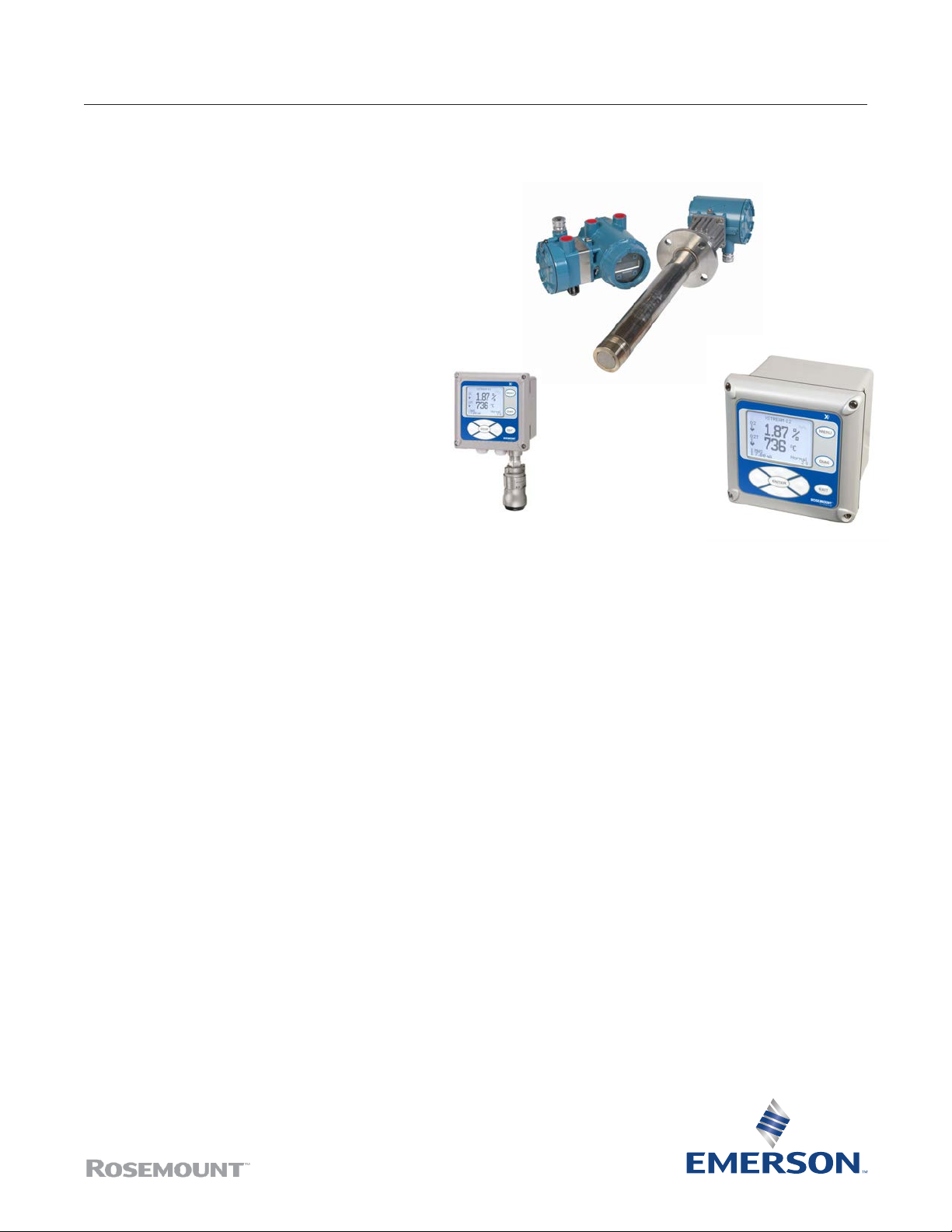
Oxymitter 4000
In Situ Oxygen Transmitter
▀ Outstanding accuracy
▀ Electronics mounted to probe
or separate
▀ Optional Xi advanced electronics
– large backlit LCD display
– advanced software features
– Wireless - via THUM Adaptor
▀ Adaptable to any existing O2 probe
installation
▀ Advanced sensor diagnostics
– alarm indicates when calibration
is recommended
▀ Optional explosion-proof ratings
▀ Digital HART
®
or FOUNDATION™
eldbus communications
– AMS/PlantWeb® compatible
▀ Fully eld-repairable
▀ Variable probe insertion option
THE LATEST BREAKTHROUGH FOR
COMBUSTION FLUE GAS ANALYSIS
The Oxymitter In Situ Oxygen Transmitter was the world’s
rst in situ, zirconium oxide-based oxygen transmitter for
ue gas measurement. These oxygen measurements can
be used in a control system or by a boiler operator to ne
tune burner fuel/air ratios for maximum efciency. Ideal for:
•
• process heaters • reheat furnaces
Emerson is the leader in oxygen ue gas analyzer technol-
ogy. Our in situ, zirconium oxide oxygen analyzers have
long been established as industry standards. We’ve combined our expertise with the latest Rosemount transmitter
technology to create a truly
revolutionary package – the Oxymitter.
The Oxymitter integrates an oxygen probe and eld
electronics into a single, compact package. The probe
inserts directly into a ue gas duct to measure oxygen in
combustion processes. No sampling system is required.
A NEMA 4X, IP 66 Rosemount transmitter housing mounts
directly to the probe and contains the transmitter’s
electronics, replacing common stand-alone eld
electronics. This integrated design minimizes the costs of
installing separate probe cable, conduit and electronics.
boilers • kilns
Wireless THUM
mounts to either electronics
Product Data Sheet
August 2017
Integral or Remote
electronics
TM
Adaptor
Optional Xi
enhanced interface
The Oxymitter electronics also require 95% less power
to operate. So, its components last longer. Traditional
architecture with remote-mounted electronics is also
offered.
The HART
Web
Instrument technicians can interface with the Oxymitter
from the control room or any location where the transmitter’s signal wires terminate. Service diagnostics and
calibrations can be performed remotely with a HART
hand-held communicator or a personal computer equipped
with AMS.
The Oxymitter is fully eld-repairable. The probe’s design
provides convenient access to internal probe components
so technicians can service the unit in house. The cell and
heater/thermocouple are fully eld-replaceable. The
Oxymitter contains no potentiometer adjustments or
jumpers.
The Oxymitter In Situ Oxygen Transmitter operates at
process temperatures up to 1300°F (700°C), providing a
fast response with high accuracy and reliability. Available
lengths from 18 inches to 18 feet.
Optional accessories for the Oxymitter include:
– auto calibration gas sequencer
– remote, loop-powered Vacuum Fluorescent display
of oxygen reading
– high temperature accessories for temperatures
up to 1832°F (1000°C)
– ame arrestor
– abrasive shield
®
protocol provides a link into Emerson’s Plant-
®
eld-based architecture.
Page 2
Oxymitter
TM
August 2017
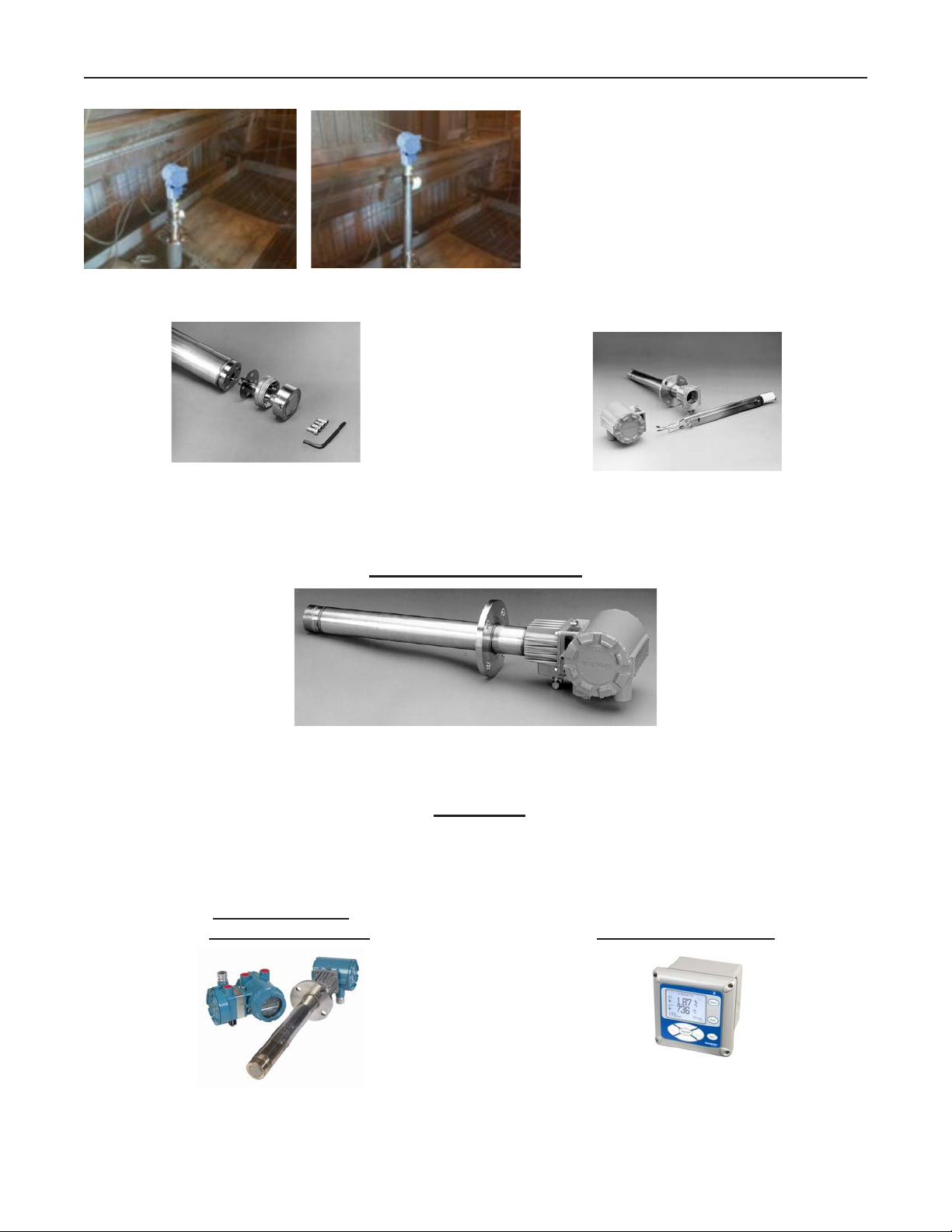
VARIABLE INSERTION OPTION
The new varible insertion option permits ideal
placement of the probe into the ue gas duct.
Probe can be adjusted at any time on-line to
characterize stratication across large ducts.
THE OXYMITTER OXYGEN TRANSMITTER IS COMPLETELY FIELD-REPAIRABLE
Diffusion Filter and Sensor Cell Assembly
•
Outstanding accuracy– + or - .75% of reading or .05% O
• Special cells for tough service in SO2 and HCL
• Rugged steel cell holder – cells will not crack
General Purpose – OXT4A
• Lengths from 18” (.9m) to 18’ (5.5m)
• ANSI, DIN and special anges (1.8m) (5.5m)
• Flat-faced (snubber), Hastelloy and Ceramic Diffusers
• -40°F to 185°F(-40°C to 70°C) ambient temperature limit
• HART or FOUNDATION™ Fieldbus communications
• “Calibration Recommended” diagnostic
Integral to Probe
or Remote Mounted
2
Heater/Thermocouple Assembly
Electronics
Xi Enhanced Interface
Easy-to-read backlit display
• Lowest cost of installation
• Bright gas uorescent local operator interface (LOI)
• Thru-glass infrared pushbuttons are suitable for hazardous areas
2 3www.Emerson.com/RosemountGasAnalysis www.Emerson.com/RosemountGasAnalysis
•
• Easy-to-use keypad
• IP66 (NEMA 4X) enclosure
• Advanced software features
• Loss of ame relay option turns heater off upon ame loss
Page 3
August 2017
Advanced Features
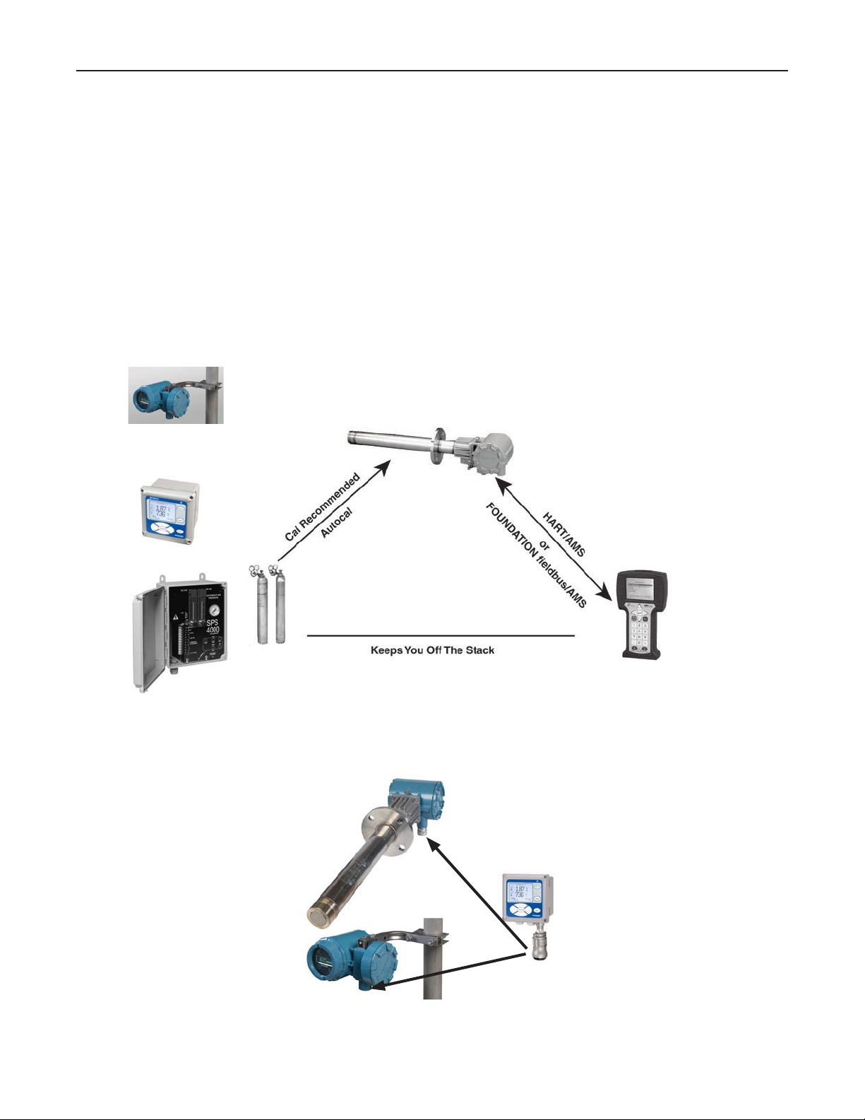
Automatic Calibration - available with Oxymitter
or Xi electronics
Plant personnel often ask how frequently an oxygen
analyzer requires calibration. The answer is very
application-dependent based upon the fuels being burned,
normal levels of oxygen and the sulfur content in the ue
gases. The X-STREAM Xi addresses this concern by
providing an on-line diagnostic that determines when
a calibration should be conducted, eliminating many
unneeded calibrations and the technician and gas
resources they consume. The X-STREAM electronics has
an on-line impedance measurement for the sensing cell.
Oxymitter or Xi Enhanced
Interface and Advanced
Feature Electronics
Oxymitter
This feature can trigger a fully automatic calibration by
sequencing solenoids to introduce calibration gases to the
sensing cell. The Single Probe Sequencer (SPS) switches
CAL gases to a single probe, while a Multi-Probe
Sequencer (IMPS) can handle 1 to 4 probes. Many
needless calibrations based on “time in service” are
eliminated. A contact closure noties the control room
when a calibration is taking place. The oxygen output
signal can be held at its last value, or released during
calibration. The X-STREAM can also initiate calibrations
by traditional methods:
• Contact closure from the user’s control room
• Time since last calibration feature – established by
the autocalibration system
• Xi enhanced interface
• HART/AMS
TM
Single Probe Sequencer (SPS)
Optional Wireless THUM Adaptor
Transmit the O
2
Model 375/475
Handheld Communicator
signal, along with all HART information.
Page 4
Oxymitter
TM
Advanced Software features (available only with the Xi electronics)
Extended Process Temperature Range to
800°C (1562°F)
The X-STREAM oxygen analyzer employs a heater and
thermocouple to maintain a temperature setpoint at 736°C
(1357°F). Temperature control is maintained within ±1°C
to process temperatures of about 705°C (1300°F). This is
satisfactory for most applications, but excursions to higher
temperatures can occur in many processes. In these
instances, the heater is turned off and the process
temperature is utilized to heat the sensing cell.
The oxygen reading is adjusted immediately to
compensate for the varying process temperatures. It
should be noted that cell life will be reduced by
continuous operation at temperatures above 705°C
(1300°F). If process temperatures are expected to
continuously be above 705°C, we recommend the use of
a bypass or probe mounting jacket accessory (see page
10).
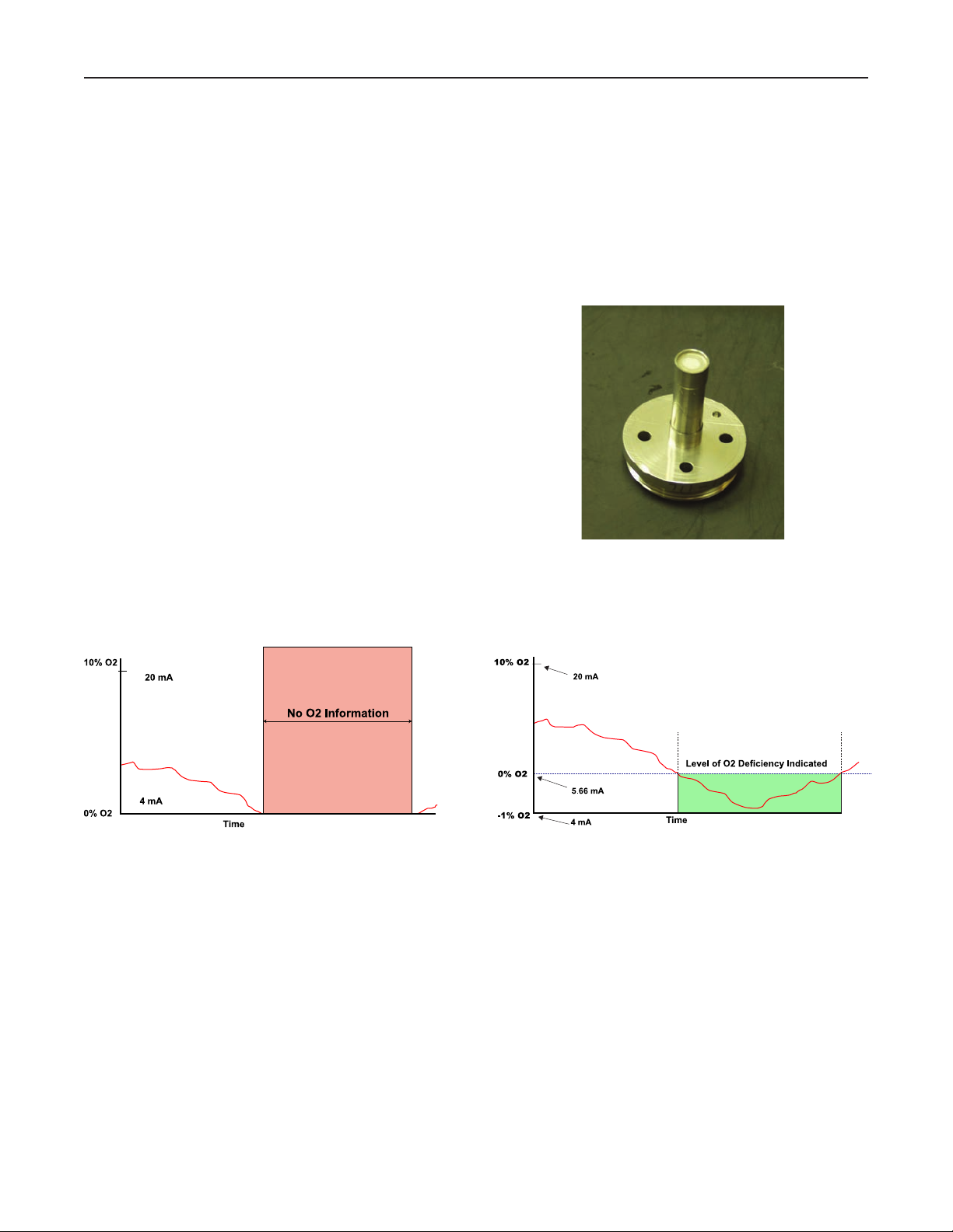
Stoichiometer
Process upsets can sometimes cause a combustion
process to go into substoichiometric or reducing conditions. The oxygen readings from one or more probes may
decline all the way to zero. The stoichiometer cell will
measure the amount of oxygen deciency during these
reducing conditions. The trends in your DCS can be set
up for a lower range limit of -1 or -2% oxygen to depict the
level of oxygen deciency.
The operator can see if his control actions to recover are
having the desired effect. These types of events do not
occur frequently, but knowing the parameters of the
situation prevents overcorrecting while coming out of the
reducing condition.
Acid-Resistant Stoichiometer Cell
August 2017
Typical DCS Trend During a Reducing Process
Event
Programmable Reference
The zirconium oxide sensing technology has historically
measured process oxygen by using ambient or instrument
air as a reference (20.95% oxygen). The sensor develops
most of its signal at the low oxygen levels typically found
in combustion ue gases (2-4% oxygen) and is most
accurate at these levels. When measuring at levels
near ambient, however, the sensor develops only a few
millivolts of signal and accuracy degrades.
The programmable reference feature permits the user
to use a bottled reference gas of low oxygen value (.4%
oxygen recommended). When measuring at or near 21%
oxygen, a strong negative oxygen signal results with much
improved accuracy. A bottle of reference gas typically lasts
about a month at the low ows required.
DCS Trend With X-STREAM Stoichiometer Feature
Typical applications include:
Flue Gas Recirculation – controlling the mixing of ue
gases into the burner windbox prior to the burner to reduce
NOx emissions.
Moisture Monitoring – measuring the amount of moisture
coming off of industrial dryers by noting the dilution effect
water vapor has on the normal 20.95% ambient drying air.
Enriched Oxygen Combustion – Pure oxygen is
sometimes mixed in with the combustion air to increase
heat at the ame. This is used in steel and other
metals reduction processes and also in some catalyst
regenerators.
4 5www.Emerson.com/RosemountGasAnalysis www.Emerson.com/RosemountGasAnalysis
Page 5

August 2017
SPECIFICATIONS
MeasurementSpecications
Net O2 Range: variable 0-10% to 0-40%
(Xi electronics offer 0-50% O2 range)
Accuracy in
Oxidizing conditions:
O2, whichever is greater
Lowest
detectable limit— .02% O
Process
Temperature Effect— less than .05% O2 from 100-700°C
System Speed of
Response to
Calibration Gas:
T90 in less than 8 seconds. Response to
process gas changes will vary, depending
on process gas velocity and particulate
loading of the diffuser
Calibration Validity: Presentation of calibration gases matches
the normal process to within ±.02% O
Accuracy in
reducing conditions: ±.10% of reading, or .1% O2, whichever
is greater
System Response in
Reducing Conditions: going from oxidizing to reducing
-T90 in 120 sec.
going from reducing to oxidizing
-T90 in 30 sec.
EnvironmentalSpecications
Transmitter Probe: Process-wetted materials are 316L or 304
stainless steel
Process
Temperature Limits: 0 to 705°C (32-1300°F) with
Oxymitter electronics
0 to 800°C (32-1472°F) with
Xi electronics
*reduced cell life can be expected if
operated continuously at temperatures
above 705°C (1300°F) optional bypass
and jacket accessories permit operation
to 1050°C (1922°F)
Oxymitter Transmitter
Electronics Housing
(integral to probe, or
remote mounted): Low copper aluminum IP 66 (NEMA 4X),
with reference air exhuast port piped to
clean area
General Purpose
Certications:
Oxymitter
electronics
ambient temp.
Limits: -40° to 80°C (-40° to 176°F)
Temperature limit
as measured inside
Oxymitter electronics: -40° to 85°C (-40° to 185°F)
Temperature limit of
see-thru
IR pushbuttons: -40° to 70°C (-40° to 158°F)
Optional
Xi Electronics: NEMA 4X, Polycarbonite Material
1
±0.75% of reading or 0.05%
2
Initial response in less than 3 seconds,
2
Oxymitter
TM
General Purpose
Certications:
Xi Ambient Temp.
Limits: -20° to 55°C (-4° to 131°F)
Xi Temp. Limits as
measured inside
the housing: -20° to 55°C (-4° to 113°F)
Xi LCD display
Temp. Limits:
-20° to 55°C (-4° to 131°F)
InstallationSpecications
Probe Mounting
Flange: vertical or horizontal — 2” 150# (4.75”
(121mm) bolt circle)
DIN (145mm (5.71”) bolt circle)
Note: anges are at-faced, and for
mounting only. Flanges are not
pressure-rated.
Spool piece P/N 3D39761G02 is available,
to offset electronics housing from hot
ductwork.
Many adaptor anges are available to
mate to existing anges.
Probe Lengths and Approximate Shipping weights:
18 in. (457 mm) package: 16 pounds (7.3 kg)
3 foot (0.91 m) package: 21 pounds (9.5 kg)
6 foot (1.83 m) package: 27 pounds (12.2 kg)
9 foot (2.74 m) package: 33 pounds (15.0 kg)
12 foot (3.66 m) package: 39 pounds (17.7 kg)
15 foot (4.6 m) package: 45 pounds (20.5 kg)
18 foot (5.5 m) package: 51 pounds (23 kg)
Reference Air
(optional): 2 scfh (1l/m), clean, dry, instrument
quality air (20.95% O2), regulated to
2.5 psi (34kPa)
Calibration: Semi-automatic or automatic
Cal Gases: .4% O2 and 8%, balance N2
recommended
Cal Gas Flow: 5 scfh (2.5 l/m)
Heater Electrical
Power: 100 - 240V, ±10% 50/60 Hz 1/2”— 14”
NPT conduit ports
Traditional
Architecture Cable: 200 foot (61m) maximum length
Power Consumption
of Probe Heater: 776VA maximum during warm-up
Electrical Power of
Oxymitter or optional
Xi electronics: 120 to 240V, ±10% 50/60 Hz
Power Consumption
of Xi: 10 watts maximum
Xi Alarms Relays: 2 provided - 2 amps, 30 VDC
Xi Optional Loss of
Flame Contact: Removes heater power
Page 6
Oxymitter
Electrical Noise:
Meets EN 61326, Class A
Traditional Architecture
Cable: 200ft (61m) maximum length
Power Consumption of
Probe Heater: 776VA maximum during warm-up
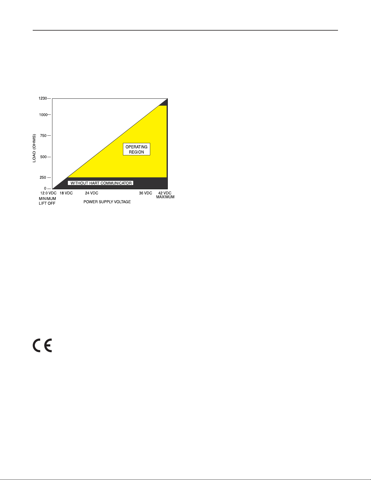
Transmitter Electrical
Power: 12 – 42VDC, (loop-powered from the
control room or from the Xi box)
TM
August 2017
General Purpose
HART communications - OXT4A pg. 11
FOUNDATION
Fieldbus Communications - OXT5A pg. 13
Direct Replacement Probe
(for use with existing electronics) - OXT4ADR pg. 15
Automatic calibration systems - XSO2Cal pg. 16
Optional Xi advanced electronics - Xi pg. 17
Power Supply and Load Requirements
Electrictical Power
for Xi: 100-240V ±10%, 50-60Hz
Power Consumption
of Xi: 12VA maximum or
776VA maximum with Traditional
Architecture, 120V, Probes.
450VA maximum with Traditional
Architecture, 44V Probes
Alarm Relay Outputs: Two provided - 2 Amperes, 30 VDO,
Form-C
Optional Loss of
Flame Input: internally powered input to remove
heater power, actuated via dry
contact output from prove of ame
device.
Emerson has satised all
obligations coming from the European legislation
to harmonize the product requirements in Europe.
operating variables constant. Specications subject
to change without notice.
1
All static performance characteristics are with
6 7www.Emerson.com/RosemountGasAnalysis www.Emerson.com/RosemountGasAnalysis
Page 7

August 2017
2.26
(58)
Oxymitter
OUTLINE DIMENSIONS FOR OXYMITTER OXYGEN TRANSMITTER FOR GENERAL
PURPOSE APPLICATIONS (OXT4A, OXT5A, OXT4ADR)
TM
Table I. Mounting Plate
Dimensions Dia. in. (mm)
ANSI DIN JIS
Mtg. Plate (x) 6.0 7.5 6.5
(153) (190) (165)
Stud Size 5/8” – 11 M16 x 2 M12 x 1.75
4 Studs Eq. 4.75 BC 5.71 BC 5.12BC
Sp. on BC (121) BC (145) BC (130) BC
Flange (Y) 6.0 7.3 6.1
(153) (185) (155)
Table II. Removal/Installation
Dim “A” Dim. “B”
Probe Insertion Removal
Length Depth Envelope
18 in. (457 mm) 16.00 28.6
Probes (407) (725)
3 ft. (0.91 m) 34.00 46.6
Probes (864) (1182)
6 ft. (1.83 m) 70.00 82.6
Probes (1778) (2097)
9 ft. (0.91 m) 106.00 118.6
Probes (2692) (3011)
12 ft. (3.66 m) 142.00 154.6
Probes (3607) (3926)
Page 8

Oxymitter
38890070
TM
OXYMITTER 4000 WITH ABRASIVE SHIELD
-
E
R
E
H
P
S
O
-
M
T
G
A
N
I
N
E
R
V
A
I
W
S
O
-
L
P
X
E
N
I
August 2017
E
V
I
L
A
T
I
U
C
R
I
C
N
E
H
W
T
H
G
I
T
P
-
E
E
K
noitcennoC
and
epolevnElavomeR
(318)
12.50
7.00
(178)
riAfeR
.LAC
SAG
6.02
(153)
4.77
(121)
ISNA
NID
NID
9.25
(235)
0.94
(24)
7.48
(190)
ISNA
(19)
0.75
eloH
7.50
(190)
aiD
9.00
(229)
egnalF
egnalF
aiD
tsuD/resuffiD
yssAlaeS
)2113(
(826)
(330)
50.5
31
86.5
(1283)
67
(787)
122.5
(2197)
103
(1702)
158.5
139
(2616)
194.5
(4026)
175
(3531)
230.5
(4940)
112
(4445)
(5855)
(5359)
32.5
tsuD/rebbunS
ylbmessAlaeS
3.9
(99)
:setoN
0.2
(5)
yssArotcelfeD
13
eborP
Note: For probes 9 ft. or longer, bracing for cell end of probe is required inside the ue gas
ductwork. (Brackets provided with abrasive shield)
8 9www.Emerson.com/RosemountGasAnalysis www.Emerson.com/RosemountGasAnalysis
Page 9

August 2017
B
OXYMITTER 4000 ADAPTOR PLATE WITH ABRASIVE SHIELD
snoisnemiD
(mm)
.ni
ISNA
NID
Oxymitter
TM
"B"
aiD
Thread
"D"
aiD
"A"
"C"
9.00
(229)
4.75
(121)
7.50
(191)
9.25
(235)
3.94
(100)
11-526.0
7.48
(190)
o
22.5
A
A
C
Page 10

Oxymitter
TM
OPTIONAL VARIABLE INSERTION MOUNTING* (OXT4A, OXT5A, OXT4ADR)
August 2017
PROBE SIZE L D X1 ±2 (51) X2 ±2 (51)
9 ft. (2.73) 118 (2997) 18 (457) < D<103 (2616) 72 (1829) –
12 ft. (3.64) 154 (3912) 18 (457) < D<139 (3531) 60 (1524) 120 (3948)
15 ft. (4.55) 190 (4826) 18 (457) < D<175 (4445) 70 (1778) 150 (3810)
18 ft. (5.45) 226 (5740) 18 (457) < D<211 (5359) 80 (2032) 160 (4064)
*Note - cannot be used with abrasion shield,
not recommended for highly abrasive ue gases
order by part #6A00319G03
10 11www.Emerson.com/RosemountGasAnalysis www.Emerson.com/RosemountGasAnalysis
Page 11

August 2017
Oxymitter
ORDERING INFORMATION – General Purpose Oxymitter with 4-20 mA Output Signal,
®
and HART
Communications. Optional Xi electronics not applicable.
TM
Model Description
OXT4A In Situ Oxygen Transmitter – HART
1 Sensing Probe Type
Level
®
Smart (Oxymitter 4000)
1 Ceramic diffusion element probe (ANSI)
3 Snubber diffusion element (ANSI)
4 Ceramic diffusion element probe (DIN)
6 Snubber diffusion element (DIN)
7 Ceramic diffusion element probe (JIS)
9 Snubber diffusion element (JIS)
Level 2 Probe Assembly
0 18” (457mm) probe
1 18” (457mm) probe with abrasive shield
2 3’ (0.91m) probe
3 3’ (0.91m) probe with abrasive shield
4 6’ (1.83m) probe
5 6’ (1.83m) probe with abrasive shield
6 9’ (2.74m) probe
7 9’ (2.74m) probe with abrasive shield
8 12’ (3.66m) probe
9 12’ (3.66m) probe with abrasive shield
A 15’ (4.57m) probe with abrasive shield
B 18’ (5.49m) probe with abrasive shield
Level 3 Mounting Hardware (stack side)
0 No mounting hardware
1 New Installation – square weld plate with studs
2 Mounting to Model 218 mounting plate (with Model 218 shield removed)
3 Mounting to existing Model 218 support shield
4 Mounting to other mounting
5 Mounting to Model 132 adapter plate
Level 4 Mounting Hardware (probe side)
0 No mounting hardware
1 Probe only (ANSI)
2 New bypass or new abrasive shield (ANSI)
4 Probe only (DIN)
5 New bypass or new abrasive shield (DIN)
7 Probe only (JIS)
8 New bypass or new abrasive shield (JIS)
Level 5 Electronic Housing and Filtered Customer Termination – NEMA 4X, IP 66
12 For HART® electronics integrally mounted to probe with transient protected ltered termination – no cable required
14 For HART® electronics mounted remotely with transient protected ltered termination – must select cable below
Level 6 Communications
1 Membrane keypad – HART capable, blind cover
2 Membrane keypad – HART capable, glass cover
3 Gas uorescent LOI HART capable, glass cover, English only
Page 12

Oxymitter
TM
ORDERING INFORMATION (continued)
August 2017
Level 7 Language
1 English
2 German
3 French
4 Spanish
5 Italian
Level 8 Termination Filtering
00 Specied as part of electronic housing
Level 9 Calibration Accessories
00 No hardware
01 Cal./ref. owmeter and ref. pressure regulator
02 Autocalibration Systems – order by separate part number (for safe areas only)
Level 10 Electronics to Probe Cable
00 No cable – integral electronics
10 20’ (6m) cable – remote electronics
11 40’ (12m) cable – remote electronics
12 60’ (18m) cable – remote electronics
13 80’ (24m) cable – remote electronics
14 100’ (30m) cable – remote electronics
15 150’ (45m) cable – remote electronics
16 200’ (61m) cable – remote electronics
12 13www.Emerson.com/RosemountGasAnalysis www.Emerson.com/RosemountGasAnalysis
Page 13

August 2017
Oxymitter
TM
ORDERING INFORMATION – Direct Replacement Oxymitter Probe replaces all older Westinghouse and Rosemount probes, as well as most competitive probes.
Operates on most existing electronics, and also on the Xi enhanced interface electronics.
Model Description
OXT4ADR In Situ Oxygen Transmitter – for use with existing electronics or Xi electronics
Level 1 Sensing Probe Type
1 Ceramic diffusion element probe (ANSI)
3 Snubber diffusion element (ANSI)
4 Ceramic diffusion element probe (DIN)
6 Snubber diffusion element (DIN)
7 Ceramic diffusion element probe (JIS)
9 Snubber diffusion element (JIS)
Level 2 Probe Assembly
0 18” (457mm) Probe
1 18” (457mm) Probe with abrasive shield
2 3’ (0.91m) Probe
3 3’ (0.91m) Probe with abrasive shield 4
4 6’ (1.83m) Probe
5 6’ (1.83m) Probe with abrasive shield 4
6 9’ (2.74m) Probe
7 9’ (2.74m) Probe with abrasive shield 4
8 12’ (3.66m)Probe 1
9 12’ (3.66m) Probe with abrasive shield
A 15’ (4.57m) Probe with abrasive shield
B 18’ (5.49m) Probe with abrasive shield
Level 3 Mounting Adapter – Stack Side
0 No adapter plate
1 Mounting to stack (new installation)
2 Mounting to model 218/225/240 mounting plate (with probe support tube removed)
3 Mounting into existing model 218/225/240 probe support tube or bypass
4 Mounting into competitor’s mounting 3
5 Model 132 / World Class 3000 adapter plate
2
4
Level 4 Mounting Adapter – Probe Side
0 No mounting hardware
1 Mounting probe only (ANSI)
2 Mounting probe with abrasive shield (ANSI)
4 Mounting probe only (DIN)
5 Mounting probe with abrasive shield (DIN)
7 Mounting probe only (JIS)
8 Mounting probe with abrasive shield (JIS)
Level 5 Termination Unit
11 Standard ltered termination
12 Transient protected ltered termination
Level 6 Arrangement-Existing Electronics
03 No hardware. For use with 218 analog electronics, world-class IFT electronics or Oxymitter electronics, Xi electronics
04 Westinghouse/Rosemount digital (218A) or universal electronics
05 VeriTrim electronics
07 Model 132 digital electronics
08 For use with Yokogawa electronics (cold junction comp. in probe junction box)
09 For use with other competitive oxygen analyzer systems
Note:
Order manual calibration accessories separately
263C152G01 Reference air regulator set
771B635H01 (2 required) owmeters for calibration and reference air
Page 14

Oxymitter
TM
Option Notes for Oxt4A, Oxt5A and Oxt4ADR
Notes: In-Situ Oxygen Transmitter – HART® Smart
High Sulfur Service:
High sulfur cell can be selected for any probe; add a line item note to your purchase order requesting the
high sulfur ZrO2 cell in place of the standard ZrO2 cell. Add 4232 UOM to the system matrix UOM total.
Example:
Note: Delete – standard cell P/N 4847B63G01
Add – high sulfur cell P/N 4847B63G02
Cell replacement kits for high sulfur service are also available. Consult P/N 4849B94XX in the
Combustion Solutions Center Spare Parts list.
Level 2: Option: 0
25/55 kgs/lbs shipping weight
Level 2: Option: 2
27/60 kgs/lbs shipping weight
Level 2: Option: 4
30/66 kgs/lbs shipping weight
Level 2: Option: 6
33/72 kgs/lbs shipping weight
Level 2: Option: 8
35/78 kgs/lbs shipping weight
Level 2: Option: 3
45/100 kgs/lbs shipping weight
Level 2: Option: 5
50/110 kgs/lbs shipping weight
Level 2: Option: 1, 7
54/120 kgs/lbs shipping weight
Level 2: Option: 9
60/130 kgs/lbs shipping weight
Level 2: Option: A
66/145 kgs/lbs shipping weight
Level 2: Option: B
72/158 kgs/lbs shipping weight
Level 2: Option: 1, 3, 5, 7, 9, A, B
Recommended usages: high velocity particulates in ue stream, installation within 10’ (3.5 m) of soot
blowers or heavy salt cake build up. Applications: pulverized coal, recovery boilers, lime kiln.
Regardless of application, abrasive shields with support brackets are recommended for 9’ (2.74 m)
and 12’ (3.66 m) , 16’ (4.57 m) and 18’ (5.49 M) probe installations, particularly horizontal installations.
Level 3: Option: 4
Where possible, specify SPS number, otherwise provide details of the existing mounting plate as follows:
Plate with studs: Bolt circle diameter, number and arrangements of studs, stud thread, stud
height above mounting plate.
Plate without studs: Bolt circle diameter, number and arrangement of holes, thread, depth of
stud mounting plate with accessories.
Level 6: Option: 1
Startup, calibration and operation can be implemented using the standard membrane keypad.
Remote access and additional functionality available via HART®/FOUNDATION Field Communications
(Model 375 Hand-held Communicator or AMS) with Oxymitter device descriptor (DD) required.
August 2017
ORDERING INFORMATION – AUTOCALIBRATION ACCESSORIES
Model Description
XSO2CAL O2 Autocalibration Accessories - apply to Oxymitter or Xi electronics. General purpose only.
Level 1 Single Probe Sequencers Autocalibration options
00 None
01 SPS 4001 Single Probe Sequencer, general purpose NEMA 4X, includes check valve for probe
Level 2 Intelligent Multiprobe Sequencers (IMPS)
00 None
01 IMPS Intelligent Probe Sequencer, single-probe, general purpose NEMX 4X, includes valve for probe
02 IMPS Intelligent Probe Sequencer, two-probe, general purpose NEMX 4X, includes valve for probe
03 IMPS Intelligent Probe Sequencer, three-probe, general purpose NEMX 4X, includes valve for probe
04 IMPS Intelligent Probe Sequencer, four-probe, general purpose NEMX 4X, includes valve for probe
05 IMPS Intelligent Probe Sequencer, single-probe, 115V heated general purpose NEMX 4X, includes valve for probe
06 IMPS Intelligent Probe Sequencer, two-probe, 115V heated general purpose NEMX 4X, includes valve for probe
07 IMPS Intelligent Probe Sequencer, three-probe, 115V heated general purpose NEMX 4X, includes valve for probe
08 IMPS Intelligent Probe Sequencer, four-probe, 115V heated general purpose NEMX 4X, includes valve for probe
09 IMPS Intelligent Probe Sequencer, single-probe, 220V heated general purpose NEMX 4X, includes valve for probe
010 IMPS Intelligent Probe Sequencer, two-probe, 220V heated general purpose NEMX 4X, includes valve for probe
011 IMPS Intelligent Probe Sequencer, three-probe, 220V heated general purpose NEMX 4X, includes valve for probe
012 IMPS Intelligent Probe Sequencer, four-probe, 220V heated general purpose NEMX 4X, includes valve for probe
14 15www.Emerson.com/RosemountGasAnalysis www.Emerson.com/RosemountGasAnalysis
Page 15

August 2017
ORDERING INFORMATION – OPTIONAL Xi ADVANCED ELECTRONICS
Model Description
XI O2 Advanced electronics
Oxymitter
TM
Level 1 Xi Type
01 Future
02 Future
03 Future
04 Traditional Architecture Xi - all signal conditioning and operator interface via the Xi. Cable required, single channel only.
05 Traditional Architecture Xi - all signal conditioning and operator interface via the Xi. Cable required, single channel only,
set up to run 44V world class probe
Level 2 Mounting
00 None
01 Panel Mount Kit with Gasket
02 2” Pipe/Wall Mount Kit
Level 3 Cable (For Traditional Architecture Xi Only)
00 None
10 20’ (6m) Cable
11 40’ (12m) Cable
12 60’ (18m) Cable
13 80’ (24m) Cable
14 100’ (30m) Cable
15 150’ (45m) Cable
16 200’ (60m) Cable
Level 4 Stoichiometer Function
00 No
01 Single Channel
02 Dual Channel, (second channel not available for traditional architecture Xi)
Level 5 Programmable Reference Function
00 No
01 Single Channel
02 Dual Channel, (second channel not available for traditional architecture Xi)
Level 6 825 Deg C Process Function
00 No
01 Single Channel
02 Dual Channel, (second channel not available for traditional architecture Xi)
NOTES: Order Direct Replacement Oxymitter probe separately - Oxt4ADR
Page 16

Oxymitter
TM
Xi Enhanced Interface - Panel Mounting Details
Xi Enhanced Interface - Wall/Surface and Pipe Mounting Details
August 2017
16 17www.Emerson.com/RosemountGasAnalysis www.Emerson.com/RosemountGasAnalysis
Page 17

August 2017
OXYMITTER ACCESSORIES
HART® Hand-held 475 Communicator
The FOUNDATION™ Fieldbus 475 Communicator is an
interface device that provides a common communication
link to HART
ments, such as the Sulfur-Resistant Oxymitter. HART
Communications Protocol permits all the information
available from the Sulfur-Resistant Oxymitter electronics
to be transmitted over standard 4-20 mA signal wires or
FOUNDATION eldbus wires. By attaching the hand-held
communicator at a termination point along the signal line,
a technician can diagnose problems and congure and
calibrate the Sulfur-Resistant Oxymitter as if he or she
were standing in front of the instrument.
Bypass Packages
The specially designed Rosemount Bypass Package
for oxygen analyzers has proven to withstand the high
temperatures in process heaters while providing the same
advantages offered by the in situ sensor. Inconel tubes
provide effective resistance to corrosion, and the other
components common to other sampling systems.
®
/FOUNDATION eldbus compatible instru-
®
Oxymitter
TM
O2 Calibration Gas Kits - pn. 6296A27G01
Rosemount’s O2 Calibration Gas and
Service Kits have been carefully designed to provide
a more convenient and fully portable means of testing,
calibrating, and servicing Rosemount’s oxygen analyzers.
These lightweight, disposable gas cylinders eliminate the
need to rent gas bottles.
Wireless THUMTM Adaptor
The Smart Wireless THUM Adaptor converts the standard
4-20mA signal from the Xi electronics to a wireless signal.
All HART information is transmitted in addition to the
process O2 value.
Page 18

Oxymitter
TM
SPECIAL ARRANGEMENTS
Special Cells for High Acid Service
Many combustion processes use fuels that contain sulfur
of HCI. Special cells provide extended life in these difcult
applications.
Catalyst Regeneration
Measure O2 in regenerators at pressures up to 50 psi.
In situ design resists plugging due to catalyst nes
Class I, Div. I, Group B, C and D. Optional pressure
balancing arrangement. Optional isolation valving system
permits installation and withdrawal while the process is
running. Specied by UOP. See Application Data Sheet
ADS 106-300F.A01.
Isolation
Valving
System
August 2017
O2 Probe in
Retracted Position
Pressure balanced in situ O
isolation valving system (probe withdrawn)
Integral Pressure
Balancing Assembly
probe with optional
2
18 19www.Emerson.com/RosemountGasAnalysis www.Emerson.com/RosemountGasAnalysis
Page 19

August 2017
Notes
Oxymitter
TM
Page 20

Oxymitter
TM
CMB-PDS-340-B01
Global Headquarters
Emerson Automation Solutions
6021 Innovation Blvd.
Shakopee, MN 55379, USA
+1 800 999 9307 or +1 952 906 8888
+1 952 949 7001
Gas.CSC@Emerson.com
North America Regional Office
Emerson Automation Solutions
8200 Market Blvd.
Chanhassen, MN 55317, USA
+1 800 999 9307 or +1 952 906 8888
+1 952 949 7001
RFQ-NA.RCCRFQ@Emerson.com
Latin America Regional Office
Emerson Automation Solutions
1300 Concord Terrace, Suite 400
Sunrise, FL 33323, USA
+1 954 846 5030
+1 952846 5121
RFQ.RMD-RCC@Emerson.com
Product Data Sheet
August 2017
Europe Regional Office
Emerson Automation Solutions Europe GmbH
Neuhofstrasse 19a P.O. Box 1046
CH 6340 Baar
Switzerland
+1 954 846 5030
+1 952846 5121
RFQ.RMD-RCC@Emerson.com
Asia Pacific Regional Office
Emerson Automation Solutions Asia Pacific Pte LTD
1 Pandan Crescent
Singapore 128461
+65 6777 8211
+65 6777 0947
Enquiries@AP.Emerson.com
Middle East and Africa Regional Office
Emerson Automation Solutions
Emerson FZE P.O. Box 17033
Jebel Ali Free Zone - South 2
+971 4 8118100
+971 4 88665465
RFQ.RMTMEA@Emerson.com
Analyticexpert.com
Linkedin.com/company/Emerson-Automation-Solutions
Twitter.com/Rosemount_News
Facebook.com/Rosemount
Youtube.com/user/RosemountMeasurement
Google.com/+RosemountMeasurement
The Emerson logo is a trademark and service mark of Emerson Electric
Co.
Rosemount and Rosemount logotype are trademarks of Emerson.
All other marks are the property of their respective owners.
© 2017 Emerson. All rights reserved.
 Loading...