

Page 1
Rosemount MCL Monochloramine System
LIQ-PDS-MCL
Product Data Sheet
July 2017
Rosemount
TM
MCL
Monochloramine System
A trusted system for making your monochloramine measurements
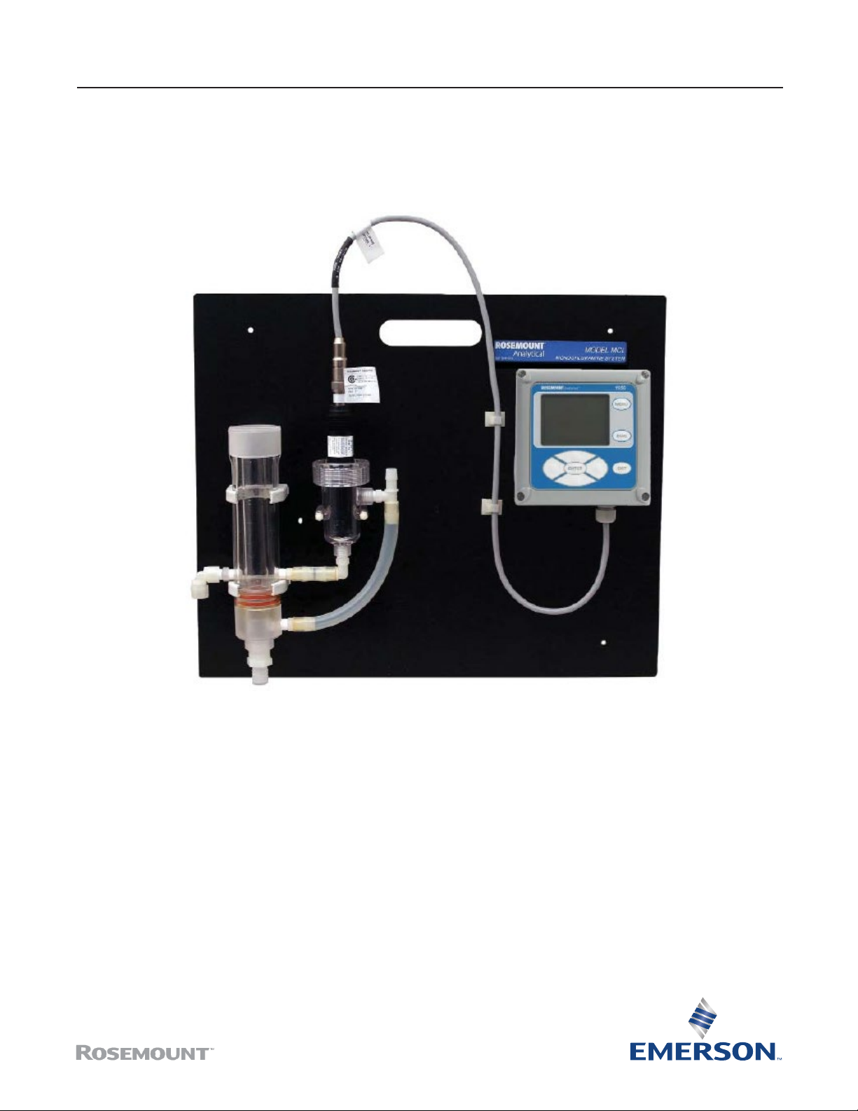
The RosemountTM MCL monochloramine system is a complete system suitable for measuring monochloramine in fresh water. The
system requires zero sample conditioning reagents.
Page 2
Rosemount MCL Monochloramine System Rosemount MCL Monochloramine System
July 2017 July 2017
Overview
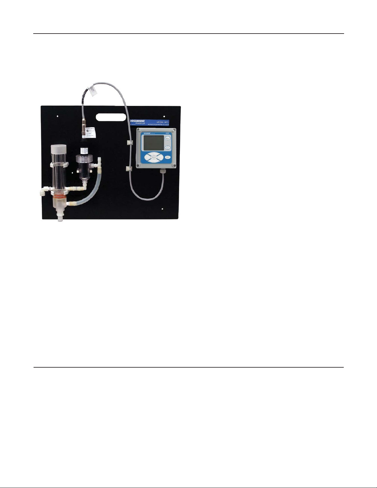
Ease of Use and Maintenance.
The Rosemount MCL features a Rosemount 499ACL-03
monochloramine sensor, a transmitter, and constant
head flow controller mounted on a backplate for easy
installation.
Integrated constant head flow controller eliminates the
need to install additional valves, rotameters, or pressure
regulators.
Easily replace and perform maintenance and calibration
on the sensor with quick-disconnect Variopol fittings.
Replacing sensor membrane and electrolyte solution
requires no special tools or fixtures and takes only
minutes.
Reliable Transmitter Options
Rosemount 56 and 1056 Transmitters are easy to use with
simple and intuitive programming and calibration.
Both transmitters have fully programmable analog
outputs and fully programmable alarm relays.
Contents
Ordering Information ........................................................................................................................................................................3
Specications ....................................................................................................................................................................................3
Dimensional Drawings .......................................................................................................................................................................6
Rosemount MCL-1056 Engineering Specication ...............................................................................................................................7
Rosemount MCL - 56 Engineering Specication ................................................................................................................................. 8
Component Parts ..............................................................................................................................................................................9
Accessories........................................................................................................................................................................................ 9
2
www.Emerson.com/RosemountLiquidAnalysis
Page 3
Ordering Information
The Rosemount MCL Monochloramine System consists of a sensor, a
transmitter, quick-disconnect Variopol cable, and constant head flow
controller. All components are mounted on a backplate, and the cable is
pre-wired to the transmitter. Three replacement membranes and a 4 oz
(120 mL) bottle of electrolyte solution are shipped with the sensor.
Table 1. Rosemount MCL Monochloramine System Ordering Information
Model Sensor type
MCL Monochloramine System
Transmitter
220 Rosemount 1056 transmitter, single input, with alarm relays (1056-03-24-38-AN)
240 Rosemount 56 Transmitter, single input (56-03-24-38-HT)
Typical model number: MCL-240
Specifications
Table 2. General Specifications
General
Sample conductivity > 10 µS/cm at 25 °C (77 °F)
Process connection 1/4 in. OD tubing compression fitting (can be removed and replaced with barbed fitting
for soft tubing).
Drain connection 1/4 in. barbed fitting. Sample must drain to open atmosphere.
Wetted parts Acrylic, nylon, polycarbonate, polyester, Kynar1, silicone, Noryl2, Viton3, silicone, and
Zitex4, PTFE , (gold mesh cathode - not normally wetted)
Response time to step change in monochloramine
concentration
Weight/shipping weight (rounded up to the nearest 1
lb or 0.5 kg)
Sample requirements
Pressure 3 to 65 psig (122 to 549 kPa abs). Inlet check valve opens at 3 psig (122 kPa abs). If the
Flow 3 to 80 gal/hr (11 to 303 L/hr)
Temperature 0 to 50 °C (32 to 122 °F)
1. Kynar is a registered trademark of Elf Atochem North America.
2. Noryl is a registered trademark of General Electric.
3. Viton is a registered trademark of E.I. duPont de Nemours & Co.
4. Zitex is a registered trademark of Performance Plastic Corp.
<60 sec to 95% of final reading for inlet sample flow of 17 gph (64 L/hr)
10 lb/143 lb (4.5 kg/6.0 kg))
check valve is removed, minimum pressure is 1 psig (108 kPa abs).
www.Emerson.com/RosemountLiquidAnalysis 3
Page 4
Rosemount MCL Monochloramine System Rosemount MCL Monochloramine System
July 2017 July 2017
Table 3. Sensor Specifications
Range 0 to 6 ppm as Cl2. For higher ranges, consult the factory.
pH range Signal is practically independent of pH between pH 7.0 and 10.0. Sensor current at pH
10.0 is within 5% of sensor current at pH 7.0.
Accuracy Accuracy depends on the accuracy of the chemical test used to calibrate the sensor.
Linearity 2% (typ.)
Interferences Free chlorine and other oxidizing agents
Electrolyte volume 25 mL (approx.)
Electrolyte life 2 months (approx.)
Table 4. Rosemount 1056 Transmitter Specifications
Display Monochromatic back-lit LCD. Main character height 0.6 in. (15 mm). Display is user-programmable.
Languages English, French, German, Italian, Spanish, Portuguese, and Chinese
Ambient temperature and humidity 0 to 55 °C (32 to 131 °F); relative humidity 5 to 95% (non-condensing)
Storage temperature -20 to 60 °C (-4 to 140 °F)
Power 85 to 265 Vac, 47.5 to 65.0 Hz, switching, 15 W
Equipment protected by double insulation.
RFI/EMI
LVD
Alarms Four alarm relays. Any relay can be configured as a fault alarm instead of a process alarm. Each relay can be
Conduit openings Accepts PG 13.5 or 1/2 in. conduit fittings
Terminal connections rating Power connector (3-leads): 18-12 AWG wire size. Current output connectors (2-leads): 24-16 AWG wire
Relay contact ratings
Relays Form C, SPDT, epoxy sealed
Case Polycarbonate NEMA 4X/CSA 4 (IP65)
Hazardous location approvals For more information, refer to the Rosemount 1056 product data sheet. Approvals apply to the transmit-
EN 61326
EN 6101-01
configured independently, and each can be programmed with interval timer settings.
size. Alarm relay terminal blocks: 18 - 16 AWG wire size
5A at 28 Vdc or 300 Vac (resistive)
1/8 HP at 120/240 Vac
ter only. The MCL is not suitable for use in hazardous areas.
4
www.Emerson.com/RosemountLiquidAnalysis
Page 5

Table 5. Rosemount 56 Transmitter Specifications
Display Full color LCD, 3.75 x 2.20 in. (95 x 56 mm); display can be customized..
Languages English, French, German, Italian, Spanish, Portuguese, Chinese, Russian, and Polish
Ambient temperature and humidity -10 to 60 °C (14 to 140 °F); relative humidity 5 to 95% (non-condensing). Between -5 and 55 °C (23 and
131 °F) there is no visible degradation in display response or performance.
Storage temperature -20 to 60 °C (-4 to 140 °F)
Power 85 to 265 Vac, 47.5 to 65.0 Hz,20 W.
RFI/EMI
LVD
Alarms and timers Four relays, fully configurable as a setpoint alarm, interval timer, TPC, bleed and feed timer, delay timer,
Outputs Four 4-20 or 0-20 mA isolated current outputs; assignable to measurement or temperature; fully scalable;
Control features PID control (analog ouput) and time proportional control or TPC (relays) are standard.
Relay contact ratings
Relays Form C, SPDT, epoxy sealed
Case Polycarbonate
Hazardous location approvals For more information, refer to the Rosemount 56 product data sheet. Approvals apply to the transmitter
Data logger Data automatically stored every 30 seconds for 30 days; older data removed to make room for new data.
Event logger Stores up to 300 events with date and time stamps: faults, warnings, calibration data, calibration results
Data and event downloading Through USB port on front panel
Graphical display Dual graphical display shows measurement data on the Y-axis and time on the X-axis. Y-axis is fully assign-
Digital communication HART digital communication is standard.
EN 61326
EN 6101-01
date and time timer, and fault alarm
maximum load 550 Ω. HART digital signal is superimposed on output 1.
5A at 28 Vdc or 300 Vac (resistive)
1/8 HP at 120/240 Vac
only. The MCL is not suitable for use in hazardous areas.
The following data are automatically stored: date and time, ppm, temperature, and raw sensor current.
(pass or fail), power on/off cycles, and hold on/off. Alarm relay activation and deactivation can also be
stored. Older events are automatically removed to make room for new events.
able and scalable. X-axis can be set to 1 hour, 1 day, 7 days, or 30 days.
www.Emerson.com/RosemountLiquidAnalysis 5
Page 6

Rosemount MCL Monochloramine System Rosemount MCL Monochloramine System
July 2017 July 2017
Dimensional Drawings
Figure 1. Rosemount MCL-220 shown. All versions of the Rosemount MCL have the same overall dimensions.
MILLIMETER
INCH
6
www.Emerson.com/RosemountLiquidAnalysis
Page 7

Rosemount MCL-1056 Engineering Specification
1. The system shall be suitable for the determination of
monochloramine in water without sample conditioning
reagents. Systems that use sample conditioning reagents
are not acceptable.
2. The system shall consist of a transmitter, a
monochloramine sensor, a ow cell for the sensor, and
a ow controller. The components shall be mounted on
a back plate. The sensor cable shall be pre-wired to the
transmitter and shall plug into the cable using a Variopol
quick disconnect tting. The ow cell shall be clear plastic
to allow the sensor to be easily inspected for fouling. The
inlet shall be tted with a check valve to ensure the sensors
remain wet in the event sample ow is lost.
3. The system shall use no mechanical devices, such as
pressure regulators, valves, or rotameters, to control ow.
Instead, ow shall be regulated using a constant head ow
controller. Minimum sample ow shall be not more than
about 3 gallons per hour (11 liters per hour). Maximum
ow can be as high as 80 gallons per hour (303 liters per
hour). The ow controller shall be able to handle inlet
pressure between 3 and 65 psig (122 and 549 kPa abs) and
temperature between 0 and 50 °C (32 and 122 °F).
4. The monochloramine sensor shall be a two electrode
membrane-covered sensor with a gold mesh cathode
and a silver/silver chloride anode. The ll solution shall
be a solution of potassium bromide in dilute acetic acid.
The sensor shall be tted with an RTD to allow continuous
correction for changes in membrane permeability caused
by temperature.
10. The transmitter shall have a four line, back-lit display. The
display shall show ppm monochloramine and temperature
on one screen. The user shall be able to customize the main
display to show additional information, such as raw sensor
current.
11. The transmitter shall be capable of operating between 0
and 55 °C (32 and 131 °F) and between 5 and 95% relative
humidity (non-condensing).
12. The transmitter shall have dual 0/4-20 isolated outputs.
Outputs shall be fully scalable and assignable independent
to monochloramine or temperature.
13. The transmitter shall have four alarm relays, fully
programmable for logic (high or low operation), deadband,
and set point. Relays can also be congured to energize
when the transmitter detects a fault with the sensor or the
transmitter.
14. All transmitter programming shall be through a front panel
membrane keypad. The language (English, Spanish, Italian,
Portuguese, German, or French) used in the menu screens
shall be selectable by the user.
15. The transmitter shall have a security feature to prevent
unauthorized tampering with calibration and conguration
settings.
16. The transmitter shall be Rosemount Model MCL-220.
5. The effect of pH on sensor response shall be less than 5%
between pH 7.0 and 10.0.
6. The linear range of the sensor shall be at least 0 to 6 ppm
as Cl2.
7. The linearity shall be about 2%.
8. The transmitter shall receive the raw signal from the
monochloramine sensor and automatically correct it for
temperature effects. Results shall be displayed as ppm Cl2.
9. The transmitter shall require single point calibration if the
expected monochloramine level is within the linear range
of the sensor. A correction for the sensor zero current shall
also be available.
www.Emerson.com/RosemountLiquidAnalysis 7
Page 8

Rosemount MCL Monochloramine System Rosemount MCL Monochloramine System
July 2017 July 2017
Rosemount MCL - 56 Engineering Specification
1. The system shall be suitable for the determination of
monochloramine in water without the use of reagents.
Systems that use sample conditioning reagents are not
acceptable.
2. The system shall consist of a transmitter, a
monochloramine sensor, a ow cell for the transmitter,
and a ow controller. The components shall be mounted
on a back plate. The sensor cable shall be pre-wired to the
transmitter, and the sensor shall plug into the cable using a
Variopol quick disconnect tting. The sensor ow cell shall
be clear plastic to allow the sensor to be easily inspected
for fouling. The inlet shall be tted with a check valve to
ensure the sensor remains wet if sample ow is lost. The
inlet connector shall be a 1/4 inch tubing compression
tting.
3. The system shall use no mechanical devices, such as
pressure regulators, valves, or rotameters, to control ow.
Instead, ow shall be regulated using a constant head ow
controller. Minimum sample ow shall be no more than
about 3 gallons per hour (11 liters per hour). Maximum
ow can be as high as 80 gallons per hour (303 liters per
hour). The ow controller shall be able to handle inlet
pressure between 3 and 65 psig (122 and 549 kPa abs) and
temperature between 0 and 50 °C (32 and 122 °F).
4. The monochloramine sensor shall be a two-electrode,
membrane-covered amperometric sensor using a gold
mesh cathode and a silver/silver chloride anode. The ll
solution shall be a solution of potassium bromide in dilute
acetic acid. The sensor shall be tted with a pt100 RTD
to allow continuous correction for changes in membrane
permeability caused by temperature.
5. The effect of pH on sensor response shall be less than 5%
between pH 8.0 and 10.0.
6. The linear range of the sensor shall be at least 0 to 6 ppm
as Cl2.
7. The linearity shall be about 2%.
8. Sensor electrolyte life shall be about four months.
9. The transmitter shall use a single point calibration based on
the results of a test run on a grab sample. A correction for
the zero current shall also be available.
10. The transmitter shall have a four line, back-lit display.
The display shall show ppm chlorine, pH (if required),
and temperature on one screen. The display shall be
programmable to show additional information, such as raw
sensor current.
11. The transmitter shall be capable of operating between -10
and 60 °C (14 and 140 °F) and between 5 and 95% relative
humidity.
12. The transmitter shall have four 0/4-20 mA isolated outputs
and HART digital communications. Outputs shall be fully
scalable and assignable independently to chlorine, pH, or
temperature. PID control shall be available as a standard
feature.
13. The transmitter shall have four alarm relays, fully
programmable as a high/low alarm with adjustable
deadband or as a timer. Timer functions shall include an
interval timer, bleed and feed timer, delay timer, and
date and time timer. Time-proportional control shall also
be available. In addition, relays shall be congurable to
energize when the transmitter detects a fault with itself or
the sensor.
14. All transmitter programming shall be through a front panel
membrane keypad. The language (English, Spanish, Italian,
Portuguese, German, French, Russian, Polish, or Chinese)
used in the menu screens shall be selectable by the user.
15. The transmitter shall have a data logger that automatically
stores data every 30 seconds for 30 days, with older data
being discarded to make room for newer data. In addition
to storing date and time, chlorine concentration, pH, and
temperature, the transmitter shall store raw sensor current
(chlorine sensor) and mV reading and glass and reference
impedance (pH sensor). Stored data shall be downloadable
through a USB port.
16. The transmitter shall have a dual graphic display that allows
data to be viewed over 1 hour, 1 day, 7 days, and 1 month
intervals.
17. The transmitter shall have a data logger that stores up to
300 events.
18. The transmitter shall have help screens, available at
the touch of a button, that provide information about
conguration, calibration, and troubleshooting.
19. The transmitter shall have a security feature to prevent
unauthorized tampering with calibration and conguration
settings.
20. The transmitter shall be Rosemount Model MCL-240 or
approved equal.
8
www.Emerson.com/RosemountLiquidAnalysis
Page 9

Component Parts
Transmitter model Description
1056-03-38-AN Rosemount 1056 Transmitter, single input, with alarm relays, 85 - 265 Vac, 47.5 - 65.0 Hz
56-03-24-38-HT Rosemount 56 Transmitter, single input, 85 - 265 Vac, 47.5 - 65.0 Hz
Sensor model Description
499ACL-03-54-VP Monochloramine sensor with Variopol connector
Sensor cabler Description
23747-04 Interconnecting cable, Variopol for Rosemount 499ACL sensor, 4 ft
Accessories
Part number Description
9240048-00 Tag, stainless steel (specify marking)
23750-00 Fill plug with wooden osmotic pressure relief port
9550094 O-ring, Viton 2-014
33521-00 Membrane retainer cap
23502-09 Monochloramine membrane kit: includes 3 membrane assemblies and 3 O-rings
9210372 Monochloramine sensor fill solution, 4 oz (120 mL)
www.Emerson.com/RosemountLiquidAnalysis 9
Page 10

Rosemount MCL Monochloramine System Rosemount MCL Monochloramine System
July 2017 July 2017
Notes
10
www.Emerson.com/RosemountLiquidAnalysis
Page 11

Notes
www.Emerson.com/RosemountLiquidAnalysis 11
Page 12

Rosemount MCL Monochloramine System
LIQ-PDS-MCL
Global Headquarters
Emerson Automation Solutions
8200 Market Blvd.
Chanhassen, MN 55317, USA
+1 800 999 9307 or +1 952 906 8888
+1 952 949 7001
Liquid.CSC@Emerson.com
Latin America Regional Office
Emerson Automation Solutions
1300 Concord Terrace, Suite 400
Sunrise, FL 33323, USA
+1 954 846 5030
+1 952846 5121
RFQ.RMD-RCC@Emerson.com
Product Data Sheet
July 2017
Europe Regional Office
Emerson Automation Solutions Europe GmbH
Neuhofstrasse 19a P.O. Box 1046
CH 6340 Baar
Switzerland
+1 954 846 5030
+1 952846 5121
RFQ.RMD-RCC@Emerson.com
Asia Pacific Regional Office
Emerson Automation Solutions Asia Pacific Pte LTD
1 Pandan Crescent
Singapore 128461
+65 6777 8211
+65 6777 0947
Enquiries@AP.Emerson.com
Middle East and Africa Regional Office
Emerson Automation Solutions
Emerson FZE P.O. Box 17033
Jebel Ali Free Zone - South 2
+971 4 8118100
+971 4 88665465
RFQ.RMTMEA@Emerson.com
Analyticexpert.com
Linkedin.com/company/Emerson-Automation-Solutions
Twitter.com/Rosemount_News
Facebook.com/Rosemount
Youtube.com/user/RosemountMeasurement
Google.com/+RosemountMeasurement
The Emerson logo is a trademark and service mark of Emerson Electric
Co.
Rosemount and Rosemount logotype are trademarks of Emerson.
All other marks are the property of their respective owners.
© 2017 Emerson. All rights reserved.
 Loading...