

Page 1
Instruction Manual
IB-106-322N Original Issue
June, 2000
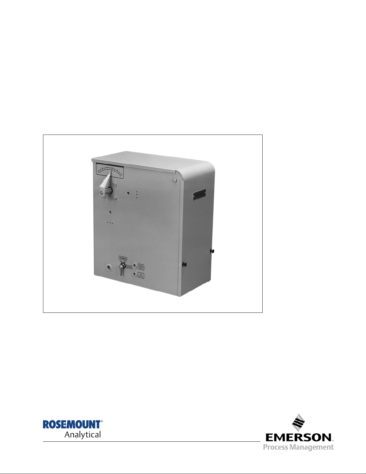
Hagan 2-1/2 x 5 and 4 x 5
Econo Torque Type Floor Mounted
Power Positioner
http://www.processanalytic.com
Page 2

ESSENTIAL INSTRUCTIONS
READ THIS PAGE BEFORE PROCEEDING!
Rosemount Analytical designs, manufactures and tests its products to meet many national and
international standards. Because these instruments are sophisticated technical products, you
MUST properly install, use, and maintain them to ensure they continue to operate within their
normal specifications. The following instructions MUST be adhered to and integrated into your
safety program when installing, using, and maintaining Rosemount Analytical products. Failure to
follow the proper instructions may cause any one of the following situations to occur: Loss of life;
personal injury; property damage; damage to this instrument; and warranty invalidation.
• Read all instructions prior to installing, operating, and servicing the product.
• If you do not understand any of the instructions, contact your Rosemount Analytical repre-
sentative for clarification.
• Follow all warnings, cautions, and instructions marked on and supplied with the product.
• Inform and educate your personnel in the proper installation, operation, and mainte-
nance of the product.
• Install your equipment as specified in the Installation Instructions of the appropriate In-
struction Manual and per applicable local and national codes. Connect all products to the
proper electrical and pressure sources.
• To ensure proper performance, use qualified personnel to install, operate, update, program,
and maintain the product.
• When replacement parts are required, ensure that qualified people use replacement parts
specified by Rosemount. Unauthorized parts and procedures can affect the product’s performance, place the safe operation of your process at risk, and VOID YOUR WARRANTY.
Look-alike substitutions may result in fire, electrical hazards, or improper operation.
• Ensure that all equipment doors are closed and protective covers are in place, except
when maintenance is being performed by qualified persons, to prevent electrical shock
and personal injury.
The information contained in this document is subject to change without notice.
Emerson Process Management
Rosemount Analytical Inc.
Process Analytic Division
1201 N. Main St.
Orrville, OH 44667-0901
T (330) 682-9010
F (330) 684-4434
e-mail: gas.csc@EmersonProcess.com
http://www.processanalytic.com
Page 3

Hagan 2-1/2 x 5 and 4 x 5
TABLE OF CONTENTS
PREFACE........................................................................................................................ P-1
Definitions ........................................................................................................................P-1
Safety Instructions .......................................................................................................... P-2
1-0 DESCRIPTION AND SPECIFICATIONS........................................................................ 1-1
1-1 General ............................................................................................................................ 1-1
1-2 Specifications................................................................................................................... 1-2
1-3 Model Number Encoding (6296A02, Rev. 2)................................................................ 1-3
2-0 INSTALLATION .............................................................................................................. 2-1
2-1 Mechanical (REFER TO Figure 2-1) ............................................................................ 2-1
2-2 Electrical .......................................................................................................................... 2-4
3-0 CALIBRATION ................................................................................................................ 3-1
3-1 Calibration Procedures ................................................................................................... 3-1
Instruction Manual
IB-106-322N Original Issue
June 2000
4-0 THEORY OF OPERATION ........................................................................................... 4-1
4-1 General ............................................................................................................................ 4-1
4-2 Pilot Valve....................................................................................................................... 4-2
5-0 MAINTENANCE .............................................................................................................. 5-1
5-1 General Maintenance Procedures................................................................................. 5-1
6-0 RETURN OF MATERIAL .............................................................................................. 6-1
7-0 ASSEMBLY DRAWINGS AND PARTS LISTINGS.................................................... 7-1
Rosemount Analytical Inc. A Division of Emerson Process Management i
Page 4

Instruction Manual
IB-106-322N Original Issue
June 2000
Figure 1-1. Model PP075T Power Positioner ........................................................................... 1-1
Figure 2-1. Model PP075T Power Positioner, Mounting Dimensions (263C469, Rev. 2) ....... 2-2
Figure 2-2. Typical Air Supply Installation ................................................................................ 2-3
Figure 2-3. Heater/Thermostat Wiring Diagram ....................................................................... 2-4
Figure 3-1. Characterized Unit, Top View ................................................................................ 3-1
Figure 3-2. Characterized Unit, Front View.............................................................................. 3-1
Figure 3-3. Noncharacterized Unit, Front View ........................................................................ 3-3
Figure 4-1. Cylinder Unit - Main Components.......................................................................... 4-1
Figure 5-1. Pilot Valve Assembly - Exploded View .................................................................. 5-3
Figure 5-2. Cylinder Assembly - Exploded View ...................................................................... 5-6
Figure 5-3. Example of Desired and Actual Process and Input Signal Relationship ............. 5-10
Figure 5-4. Blank Scale Layouts for Developing Cam Contour ............................................. 5-11
Figure 5-5. Example of Field Shaped Cam Plot ..................................................................... 5-11
Figure 7-1. Model PP075T Power Positioner (Sheet 1 of 16).................................................. 7-2
Figure 7-2. 4 X 5 Power Positioner (Sheet 1 of 2) ................................................................. 7-18
Figure 7-3. 2-1/2 x 5 Power Positioner (Sheet 1 of 2)............................................................ 7-20
Figure 7-4. Air Supply Filter.................................................................................................... 7-22
Figure 7-5. Feedback Lever on Roller Assembly................................................................... 7-23
Figure 7-6. Main Shaft Assembly ........................................................................................... 7-24
Hagan 2-1/2 x 5 and 4 x 5
LIST OF ILLUSTRATIONS
LIST OF TABLES
Table 5-1. Troubleshooting Chart ........................................................................................... 5-5
Table 5-2. Tabulation of Percent Input Signal vs. Percent Cam Rotation ............................ 5-10
ii Rosemount Analytical Inc. A Division of Emerson Process Management
Page 5
Hagan 2-1/2 x 5 and 4 x 5
The purpose of this manual is to provide information concerning the components, functions, installation and maintenance of the Hagan 2-1/2 x 5 and 4 x 5 Econo Torque Type
Floor Mounted Power Positioner.
Some sections may describe equipment not used in your configuration. The user should
become thoroughly familiar with the operation of this module before operating it. Read
this instruction manual completely.
The following definitions apply to WARNINGS, CAUTIONS, and NOTES found throughout this
publication.
Instruction Manual
IB-106-322N Original Issue
June 2000
PREFACE
DEFINITIONS
Highlights an operation or maintenance
procedure, practice, condition, statement, etc. If not strictly observed, could
result in injury, death, or long-term
health hazards of personnel.
Highlights an essential operating procedure,
condition, or statement.
: EARTH (GROUND) TERMINAL
: PROTECTIVE CONDUCTOR TERMINAL
: RISK OF ELECTRICAL SHOCK
: WARNING: REFER TO INSTRUCTION BULLETIN
NOTE TO USERS
Highlights an operation or maintenance
procedure, practice, condition, statement, etc. If not strictly observed, could
result in damage to or destruction of
equipment, or loss of effectiveness.
NOTE
The number in the lower right corner of each illustration in this publication is a manual illustration number. It is not a part number, and is not related to the illustration in any technical
manner.
Rosemount Analytical Inc. A Division of Emerson Process Management P-1
Page 6
Instruction Manual
IB-106-322N Original Issue
June 2000
FOR THE WIRING AND INSTALLATION
The following safety instructions apply specifically to all EU member states. They should
be strictly adhered to in order to assure compliance with the Low Voltage Directive. NonEU states should also comply with the following unless superseded by local or National
Standards.
1. Adequate earth connections should be made to all earthing points, internal and external,
where provided.
2. After installation or troubleshooting, all safety covers and safety grounds must be replaced.
The integrity of all earth terminals must be maintained at all times.
3. Mains supply cords should comply with the requirements of IEC227 or IEC245.
Hagan 2-1/2 x 5 and 4 x 5
IMPORTANT
SAFETY INSTRUCTIONS
OF THIS APPARATUS
4. All wiring shall be suitable for use in an ambient temperature of greater than 75°C.
5. All cable glands used should be of such internal dimensions as to provide adequate cable
anchorage.
6. To ensure safe operation of this equipment, connection to the mains supply should only be
made through a circuit breaker which will disconnect all circuits carrying conductors during a
fault situation. The circuit breaker may also include a mechanically operated isolating switch.
If not, then another means of disconnecting the equipment from the supply must be provided
and clearly marked as such. Circuit breakers or switches must comply with a recognized
standard such as IEC947. All wiring must conform with any local standards.
7. Where equipment or covers are marked with the symbol to the right, hazard-
ous voltages are likely to be present beneath. These covers should only be
removed when power is removed from the equipment — and then only by
trained service personnel.
8. Where equipment or covers are marked with the symbol to the right, there is a
danger from hot surfaces beneath. These covers should only be removed by
trained service personnel when power is removed from the equipment. Certain surfaces may remain hot to the touch.
9. Where equipment or covers are marked with the symbol to the right, refer to
the Operator Manual for instructions.
10. All graphical symbols used in this product are from one or more of the follow-
ing standards: EN61010-1, IEC417, and ISO3864.
P-2 Rosemount Analytical Inc. A Division of Emerson Process Management
Page 7
Hagan 2-1/2 x 5 and 4 x 5
1
DESCRIPTION AND SPECIFICATIONS
Instruction Manual
IB-106-322N Original Issue
June 2000
SECTION 1
1-1 GENERAL
The Rosemount Model PP075T Econo Torque
Power Positioner (Figure 1-1) is a pneumatic,
double-acting, piston-type power positioner. The
unit converts a pneumatic input signal to a corresponding mechanical movement for positioning devices such as guide vanes, control valves,
and dampers.
As shown by the model number explanation in
paragraph 1-3, the positioner can be supplied
with either a 2-1/2 x 5 in. or 4 x 5 in. cylinder, as
required. Both cylinders are available with either
direct linear feedback or characterized cam
feedback depending upon system application. A
non-characterized unit can easily be converted
in the field to a characterized version with the
addition of a few bolt-on parts. Consult the factory for details.
Other options include an auto/manual transfer
valve, brake, limit switches, and heater/
thermostat.
Figure 1-1. Model PP075T Power Positioner
Rosemount Analytical Inc. A Division of Emerson Process Management Description and Specifications 1-1
Page 8

Instruction Manual
IB-106-322N Original Issue
June 2000
1-2 SPECIFICATIONS
Refer to Descriptive Bulletin 100-322.
Repeatability........................................................ 3% of Full Stroke
Sensitivity ............................................................ 6% of Full Stroke
Temperature Limit ............................................... 40° to 170° F (4° to 77° C)
Full Stroke
Time (unloaded) ....................................... 2 seconds or less
Air Supply
Maximum .................................................. 120 psi (827.4 kPa)
Minimum ................................................... 45 psi (310.3 kPa)
Recommended ......................................... 100 psi (689.5 kPa)
Air Consumption.................................................. 0.4 SCFM (11.3 L/min.)
Free Air
Hagan 2-1/2 x 5 and 4 x 5
Torque Load Data based on recommended air supply
Small Torque ............................................ 120 ft-lbs (162.7 N·m)
Control Torque.......................................... 75 ft-lbs (101.7 N·m)
Maximum Friction
Load.......................................................... 30 ft-lbs (40.7 N·m)
Maximum Allowable
Weight Load ............................................. 45 ft-lbs (60.0 N·m)
Input Signal ......................................................... 3-15, 3-27, or 0-30 psi (20.7-103.4, 20.7-186.2,
or 0-116.9 kPa)
Output Shaft Angle .............................................. 80°
Unit Weight.......................................................... 60 lbs (27.2 g)
1-2 Description and Specifications Rosemount Analytical Inc. A Division of Emerson Process Management
Page 9

Hagan 2-1/2 x 5 and 4 x 5
1
1-3 MODEL NUMBER ENCODING
(6296A02, REV. 2)
The complete model number for the Model
PP075T Power Positioner is derived as follows:
Pneumatic Power Positioner
Control Torque Rating – ft-lbs
Econo Torque Floor Mounted
Positioner Type
1 Noncharacterized
2 Characterized
Positioner Size (diameter and stroke in inches)
1 2-1/2 x 5 Cylinder
2 4 x 5 Cylinder
Instruction Manual
IB-106-322N Original Issue
June 2000
MODEL PP075T
Signal Range
1 3-15 psig (20.7-103.4 kPa)
2 3-27 psig (20.7-186.2 kPa)
3 0-30 psig (0-116.9 kPa)
4 4-20 mA (I/P Transducer mounted and piped)
Manual and Break Operation
0 None
1 Manual Operator Only
2 Manual Operator and Brake
3 Manual Operator, Manual Lock, and Soft Air Lock
4 Manual Operator, Manual Lock, and Fail Safe (fails to 100%)
Limit Switches
0 None
2 Two SPDT switches
3 Electric Positioner Transmitter (EPT)
4 Two SPDT Switches and EPT
Heater/Thermostat
0 None
1 117 Vac, 150 watt Heater with Thermostat
Rosemount Analytical Inc. A Division of Emerson Process Management Description and Specifications 1-3
Page 10

Instruction Manual
IB-106-322N Original Issue
June 2000
Hagan 2-1/2 x 5 and 4 x 5
1-4 Description and Specifications Rosemount Analytical Inc. A Division of Emerson Process Management
Page 11

Hagan 2-1/2 x 5 and 4 x 5
2
INSTALLATION
Instruction Manual
IB-106-322N Original Issue
June 2000
SECTION 2
2-1 MECHANICAL (Refer to Figure 2-1)
a. Location Selection
The power positioner should be located in a
dry area free of excessive shock and vibration with a continuous ambient temperature
meeting specifications listed in paragraph
1-2.
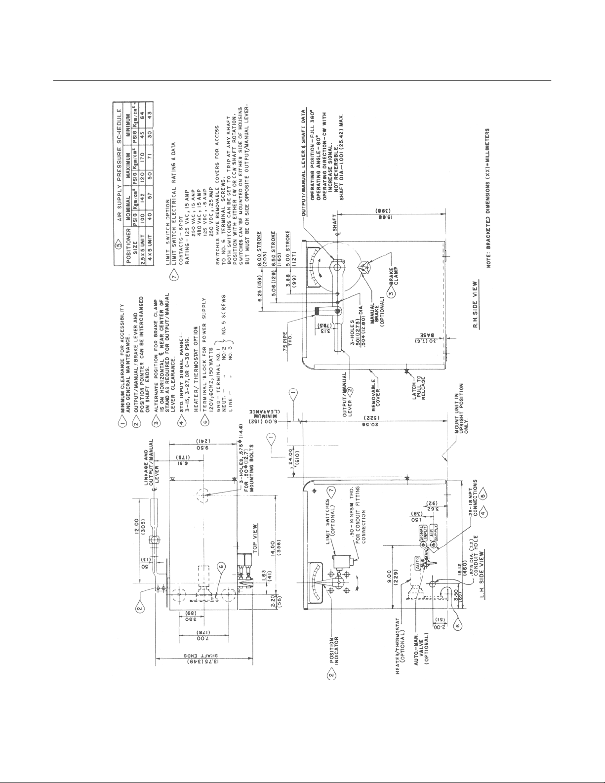
Sufficient clearance must be allowed for the
operating lever. Allow a 24 in. (610 mm)
minimum working space for front cover removal and maintenance.
b. Mount Power Positioner
The power positioner is designed to be
mounted in an upright position. The base of
the unit can be bolted to a horizontal surface using three 0.5 in. (12.7 mm) diameter
mounting bolts (not supplied).
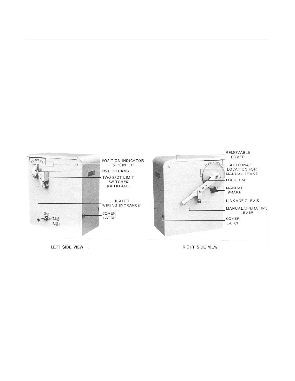
c. Position Operating Lever, Output Indica-
tor, and Manual Brake (Optional)
The operating lever, output indicator, and
manual brake (optional) can be installed on
either side of the power positioner as desired. This allows the unit to be used for
either right-hand or left-hand external linkage operation.
As viewed from the right side of the power
positioner, the operating lever will move
clockwise with an increasing input signal
(not reversible). To change the motion of
the operating lever with respect to the input
signal, the operating lever must be positioned on the left side of the power positioner or rotated 180 degrees.
The operating lever has an 80 degree operating angle range and can be installed at
any position around the shaft.
To prevent interference between the brake
clamp and the operating lever, provision
has been made to allow the brake clamp to
be located on either the shaft vertical or
horizontal centerline on either side of the
stand (Figure 2-1).
d. Position Limit Switches (Optional)
Both SPDT switches can be mounted on
either side of the housing; however, they
must be located on the side opposite the
output/manual lever.
The switches can be set to trip at any
position.
Rosemount Analytical Inc. A Division of Emerson Process Management Installation 2-1
Page 12
Instruction Manual
IB-106-322N Original Issue
June 2000
Hagan 2-1/2 x 5 and 4 x 5
Figure 2-1. Model PP075T Power Positioner, Mounting Dimensions (263C469, Rev. 2)
2-2 Installation Rosemount Analytical Inc. A Division of Emerson Process Management
Page 13
Hagan 2-1/2 x 5 and 4 x 5
2
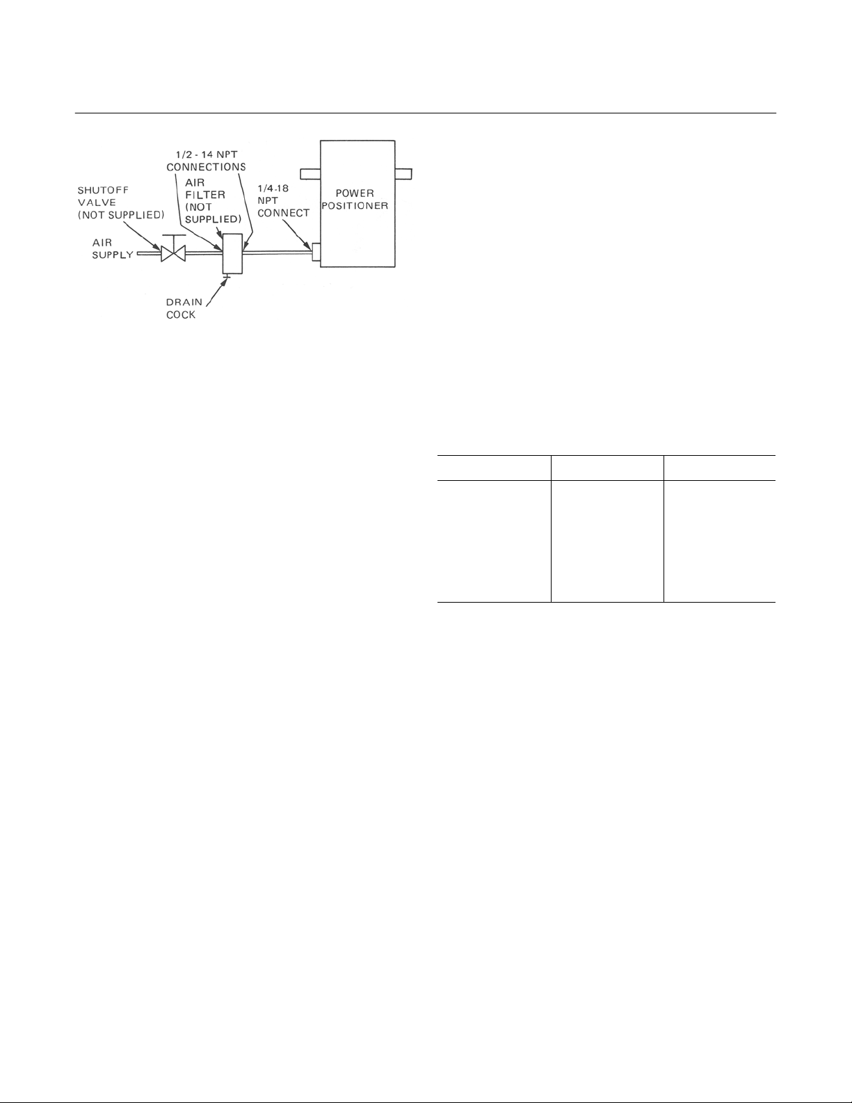
Figure 2-2. Typical Air Supply Installation
e. Connect Air Supply Piping
The air supply piping should be installed
with a manual shutoff valve and air filter as
shown in Figure 2-2. The shutoff valve is
necessary to isolate the power positioner
during servicing. Copper tubing with 1/4
inch O.D. and 0.035 in. (0.89 mm) wall
thickness is recommended for piping to the
air supply connection. A sealant may be
used, if necessary, to prevent leakage at
the connections. Use sparingly.
Air filter P/N 771B920 must be used in order
to provide reliable, continuous service.
When connected properly, the air filter will
remove finely dispersed water or oil droplets
from the air supply, thereby preventing
sticking action in the pilot valve. Port 2 (inlet) is connected to the air supply; Port 1
(outlet) is connected to the power
positioner.
Prior to connecting the air supply line to the
power positioner, the supply line should be
purged as follows:
1. Purge air supply line before connecting
air filter.
IB-106-322N Original Issue
2. Connect air filter and open drain cock.
3. Slowly open the air shutoff valve and
allow moisture and foreign particles to
be blown out through the drain cock.
4. Close the drain cock and allow compressed air to blow through the open
end of the air supply piping until all dirt
and foreign particles are blown out.
5. Shut off the compressed air supply.
6. Connect the air supply line to the 0.2518 NPT female connection on the
power positioner, Figure 1-1.
Air supply pressures are as follows:
2-1/2 x 5 Unit 4 x 5 Unit
Recommended 100 psig
(689.5 kPa)
Maximum 120 psig
(827.4 kPa)
Minimum 45 psig
(310.3 kPa)
f. Connect Input Signal Piping
Prior to connecting the input signal piping to
the power positioner, blow out piping by operating the relay station at the control panel
and manually set up a signal pressure between 50 and 100 percent. Allow the air to
blow through the open end of the tubing.
Reduce the signal pressure to zero and
connect the signal piping to the 0.25-18
NPT female connection (Figure 2-1) on the
power positioner.
Instruction Manual
June 2000
40 psig
(275.8 kPa)
50 psig
(344.8 kPa)
30 psig
(206.9 kPa)
Rosemount Analytical Inc. A Division of Emerson Process Management Installation 2-3
Page 14
Instruction Manual
IB-106-322N Original Issue
June 2000
Hagan 2-1/2 x 5 and 4 x 5
2-2 ELECTRICAL
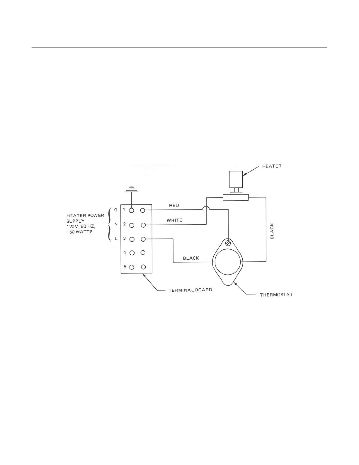
a. Heater/Thermostat Wiring (Optional)
Heater power consumption is 150 watts
using a 120 Vac, 60 Hz power source.
Feed the heater power supply wiring
through the 0.5 in. (12.7 mm) conduit hole
located on the lower left-hand side of the
housing (Figure 1-1) and connect to the internal terminal board using the No. 5 connection screws (Figure 2-3).
b. Limit Switch Wiring (Optional)
Each switch has a 0.5-14 NPSM threaded
opening suitable for a 0.5 in. (12.7 mm)
flexible conduit fitting. A removable cover on
the switch permits access to No. 6 screw
terminals.
Electrical ratings for the limit switch SPDT
contacts are as follows:
15.00A at 125 Vac, 250 Vac, or 480 Vac
0.50A at 125 Vdc
0.25A at 250 Vdc
Figure 2-3. Heater/Thermostat Wiring Diagram
2-4 Installation Rosemount Analytical Inc. A Division of Emerson Process Management
Page 15
Hagan 2-1/2 x 5 and 4 x 5
3
CALIBRATION
3-1 CALIBRATION PROCEDURES
The power positioner must be calibrated so that
the piston is at its lower limit when the control
signal is at minimum pressure and moves to its
upper limit when the signal is increased to
maximum pressure.
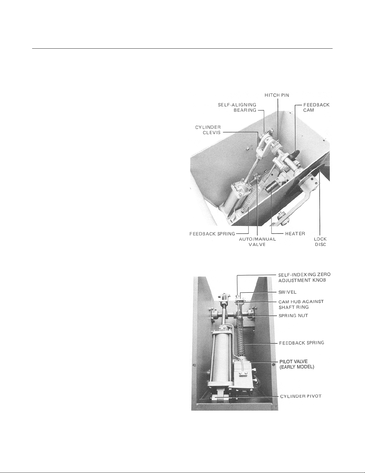
a. Characterized Units (Figure 3-1 and
Figure 3-2).
1. Using the manual/operating lever, position the piston against its lower stop.
2. Disconnect the external mechanical
linkage at the clevis (Figure 1-1).
Instruction Manual
IB-106-322N Original Issue
June 2000
SECTION 3
3. Slide the feedback cam (Figure 3-1)
mounted on a split hub clamp along the
output shaft until hub clamp bears
against the right side of the shaft ring
(Figure 3-2).
4. Rotate the cam until the roller on feedback lever (51, Figure 7-1) drops into
the cam pocket and just starts to rise
out of the pocket. At this point, there
will be a slight upward movement at
the swivel end of the feedback lever.
NOTE
The feedback spring should be under
some slight tension to ensure the cam
roller contacts the cam face.
5. At this position, tighten the hub on the
output shaft.
6. Apply minimum control signal to the
pilot valve. The piston should move to
the lowest position, against bottom
cylinder head. Check this zero adjust in
the following manner:
Figure 3-1. Characterized Unit, Top View
(a) Maintain minimum control signal
on the pilot valve.
(b) Loosen the set screw on the posi-
tioner arm.
Rosemount Analytical Inc. A Division of Emerson Process Management Calibration 3-1
Figure 3-2. Characterized Unit, Front View
Page 16

Instruction Manual
IB-106-322N Original Issue
June 2000
Hagan 2-1/2 x 5 and 4 x 5
(c) Move the positioner arm up until
the piston moves to the bottom of
the cylinder.
(d) Move the positioner arm down until
the piston begins to move upward.
(e) Move the positioner arm down until
the piston just returns to lowest
position.
(f) Lock this setting by tightening the
set screw until the positioner arm
binds to the piston rod.
7. With the piston at the bottom of the
cylinder, place a mark on either the
clevis or the 0.5 in. (12.7 mm) diameter
chrome-plated piston rod. The mark is
for use in measuring the piston stroke.
If the stroke is not correct, increase or
decrease the number of active coils in
the calibration spring. Active coils are
those that are free of the positioner
arm and that flex when under load.
Determine stroke by increasing control
signal pressure slowly and observing
travel of the mark (discussed in preceding paragraph).
(a) If the piston moves to upper limit
before the control signal reaches
maximum pressure, the number of
active coils must be decreased as
described in step 8.
(c) Determine the exact control signal
pressure at which the piston
reaches upper limit.
(d) Determine the number of active
coils required by using the following equation:
Pa
x Ca =
Pm
Where:
Pa = Signal pressure at which
Pm = Maximum control signal
Ca = Actual number of active
(e) Reduce active coils to the number
required by turning the calibration
spring further onto the positioner
arm.
(f) Repeat step 7 to check the stroke
again.
9. To increase the number of active coils,
use the following procedure:
(a) Reduce control signal to zero.
(b) Count active coils of calibration
spring. Active coils are those that
are free of the positioner arm and
that flex when under load.
Number of active
coils required
piston reaches upper limit
pressure to be used
coils
(b) If piston travel is less than desired
when maximum signal is applied,
the number of active coils must be
increased as described in step 9.
Maximum travel is approximately 5
in. (127 mm).
(c) If piston stroke is satisfactory,
perform steps 10, 11, and 12.
8. To decrease the number of active coils,
use the following procedure:
(a) Reduce control signal to zero.
(b) Count the active coils of calibration
spring. Active coils are those that
are free of the positioner arm and
that flex when under load.
3-2 Calibration Rosemount Analytical Inc. A Division of Emerson Process Management
(c) Determine exact piston stroke by
measuring amount of travel of the
mark (on piston rod or clevis) when
control signal is increased from
zero to maximum pressure.
(d) Determine the number of active
coils required by using the following equation:
Sr
x Ca =
Sa
Where:
Sa = Actual stroke
Pm = Required stroke
Ca = Actual number of active
Number of active
coils required
coils
Page 17
Hagan 2-1/2 x 5 and 4 x 5
3
Instruction Manual
IB-106-322N Original Issue
June 2000
(e) Increase the number of active coils
by turning spring off of the positioner arm.
(f) Repeat step 7 to see if desired
stroke is obtained.
10. Repeat step 6 to check minimum setting again.
11. Check mechanical linkage between the
positioner and the damper or valve that
the positioner positions. All links must
be properly aligned.
12. Reconnect mechanical linkage to
clevis.
b. Noncharacterized Units (Figure 3-3).
1. Using the manual/operating lever, position the piston against its lower stop.
2. Disconnect the external mechanical
linkage at the clevis, Figure 1-1.
3. Apply minimum control signal to the
pilot valve. The piston should move to
the lowest position, against bottom
cylinder head. Check this zero adjust in
the following manner:
(a) Maintain minimum control signal
on the pilot valve.
(b) Loosen the set screw on the posi-
tioner arm.
(c) Move the positioner arm up until
the piston moves to the bottom of
the cylinder.
(d) Move the positioner arm down until
the piston begins to move upward.
(e) Move the positioner arm down until
the piston just returns to lowest
position.
(f) Lock this setting by tightening the
set screw until the positioner arm
binds to the piston rod.
4. With the piston at the bottom of the
cylinder, place a mark on either the
clevis or the 0.5 in. (12.7 mm) diameter
chrome-plated piston rod. The mark is
for use in measuring the piston stroke.
If the stroke is not correct, increase or
decrease the number of active coils in
the calibration spring. Active coils are
those that are free of the positioner
arm and that flex when under load.
Determine stroke by increasing control
signal pressure slowly and observing
travel of the mark (discussed in preceding paragraph).
(a) If the piston moves to upper limit
before the control signal reaches
maximum pressure, the number of
active coils must be decreased as
described in step 5.
(b) If piston travel is less than desired
when maximum signal is applied,
the number of active coils must be
increased as described in step 6.
Figure 3-3. Noncharacterized Unit, Front View
Rosemount Analytical Inc. A Division of Emerson Process Management Calibration 3-3
Maximum travel is approximately 5
in. (127 mm).
Page 18

Instruction Manual
IB-106-322N Original Issue
June 2000
Hagan 2-1/2 x 5 and 4 x 5
(c) If piston stroke is satisfactory,
perform steps 7, 8, and 9.
5. To decrease the number of active coils,
use the following procedure:
(a) Reduce control signal to zero.
(b) Count the active coils of calibration
spring. Active coils are those that
are free of the positioner arm and
that flex when under load.
(c) Determine the exact control signal
pressure at which the piston
reaches upper limit.
(d) Determine the number of active
coils required by using the following equation:
Pa
x Ca =
Pm
Where:
Pa = Signal pressure at which
Pm = Maximum control signal
Ca = Actual number of active
(e) Reduce active coils to the number
required by turning the calibration
spring further onto the positioner
arm.
(f) Repeat step 4 to check the stroke
again.
6. To increase the number of active coils,
use the following procedure:
(a) Reduce control signal to zero.
Number of active
coils required
piston reaches upper limit
pressure to be used
coils
(b) Count active coils of calibration
spring. Active coils are those that
are free of the positioner arm and
that flex when under load.
(c) Determine exact piston stroke by
measuring amount of travel of the
mark (on piston rod or clevis) when
control signal is increased from
zero to maximum pressure.
(d) Determine the number of active
coils required by using the following equation:
Sr
x Ca =
Sa
Where:
Sa = Actual stroke
Pm = Required stroke
Ca = Actual number of active
(e) Increase the number of active coils
by turning spring off of the positioner arm.
(f) Repeat step 4 to see if desired
stroke is obtained.
7. Repeat step 3 to check minimum setting again.
8. Check mechanical linkage between the
positioner and the damper or valve that
the positioner positions. All links must
be properly aligned.
9. Reconnect mechanical linkage to
clevis.
Number of active
coils required
coils
3-4 Calibration Rosemount Analytical Inc. A Division of Emerson Process Management
Page 19

Hagan 2-1/2 x 5 and 4 x 5
4
THEORY OF OPERATION
Instruction Manual
IB-106-322N Original Issue
June 2000
SECTION 4
4-1 GENERAL
The piston assembly and power take-off clevis
of the power positioner (Figure 4-1) move away
from the mounting pivot with an increase in
control signal pressure. Movement of the piston,
which is equipped with graphite-impregnated
teflon piston cups, begins when the increasing
NOTE: AN ASTERISK (*) INDICATES ITEMS ARE
INCLUDED IN THE PILOT VALVE ASSEMBLY.
POSITIONER ARM
control signal at the pilot valve assembly causes
the stainless steel stem to move downward from
the neutral setting. The pilot valve assembly
then directs power air through the bottom tubing
assembly to the bottom of the aluminum cylinder and exhausts air at the other end of the cylinder to atmosphere. The resulting pressure
difference across the piston moves it upward.
POWER TAKE-OFF CLEVIS
TOP HEAD ASSEMBLY
DIAPHRAGM
ASSEMBLY*
INPUT SIGNAL
(CONTROL AIR)
(CUSTOMER
SUPPLIED)
POWER AIR
(CUSTOMER
CYLINDER
CALIBRATION
SPRING
TEFLON
PISTON CUPS
SUPPLIED)
PILOT VALVE
ASSEMBLY
STEM AND SLEEVE ASSEMBLY*
Figure 4-1. Cylinder Unit - Main Components
TOP TUBING ASSEMBLY
PISTON ASSEMBLY
(INCLUDES TEFLON CUPS)
BOTTOM TUBING
ASSEMBLY
MOUNTING PIVOT
35960001
Rosemount Analytical Inc. A Division of Emerson Process Management Theory of Operation 4-1
Page 20

Instruction Manual
IB-106-322N Original Issue
June 2000
Hagan 2-1/2 x 5 and 4 x 5
Characterized power positioners employ a
feedback cam in series with the calibration
spring, adjusting linkage, and the output shaft.
The shape of the cam affects the force exerted
by the feedback spring, thereby providing the
desired relationship between the piston position
and the input air pressure signal.
Two cams are available for the positioner. The
normally supplied standard linear cam has a linear function on one half and a square function
on the other half. The other cam (optional) has a
square root function on one half with the other
half blank for cutting a special function in the
field.
The AUTO/MANUAL valve (optional) allows the
operating lever to be used for manual positioning. In MANUAL, the air supply to the pilot valve
will be blocked off and the manual brake clamp
can be applied to hold the unit in the desired
position.
As the piston moves upward, it raises the upper
end of the calibration spring. Tension in the
spring is the feedback force in the pilot valve
assembly. Piston movement continues until the
spring force equals the force from the control
signal, which restores the pilot valve stem to the
neutral position. This blocks the flow of power
air to cylinder and prevents further piston
movement until signal pressure changes again.
For each control signal pressure, the piston is at
a particular distance from the bottom of the cylinder. At the minimum signal, it is at the lowest
point in the cylinder. At the maximum signal, it is
at the upper limit, a distance of 5 in. (127 mm)
from the lowest point. At any other signal, the
distance from the bottom of the cylinder is proportional to the signal pressure. Full stroke time
is two seconds or less. Toggling of the piston
rod at or near full stroke is prevented by the
large area guide bearings, which are set relatively far apart in the top head assembly. The
guide bearings are made of sintered teflon.
4-2 PILOT VALVE
The pilot valve is a force/balance device. The
pilot valve makes use of an external calibration
spring (connected to the positioner arm), an internal dual-diaphragm assembly, and a sleeve
and stem assembly.
Pilot valve operation is determined by the interaction of two primary forces:
a. A downward force developed by the control
signal as it acts upon the diaphragm assembly.
b. An upward force created by the tension of
the calibration spring.
In operation, the pilot valve diaphragm assembly moves up or down and repositions the stem
when the force of the calibration spring and the
force due to the signal pressure are not in balance. Starting with the stem in the neutral position, an increase of the control signal pressure
causes a downward movement of the pilot valve
diaphragm assembly. This forces the stem
downward, uncovering ports in a stainless
sleeve which permit power air to flow into the
lower end of the cylinder and the air in the upper
end to exhaust to atmosphere. The piston
moves upward and pulls on the calibration
spring. Tension in this spring increases until it
balances the force due to the control signal
acting in the diaphragm assembly. The stem
then returns to the neutral position and blocks
the ports in the sleeve, which prevents further
movement of the piston.
With a decrease in control signal pressure, the
opposite actions occur. In this case, the force
due to the control signal becomes less than the
force of the calibration spring. The spring then
pulls the spring post and stem seat upward. The
stem is pushed upward by the spring in the pilot
valve assembly and uncovers ports that transmit
power air from the pilot valve to the top of the
cylinder and exhaust the bottom of the cylinder.
The piston then moves downward, which reduces the tension in the calibration spring until it
balances the force due to the lower control signal. The pilot valve assembly stem will then be
in the neutral position again and prevent further
movement of the piston.
4-2 Theory of Operation Rosemount Analytical Inc. A Division of Emerson Process Management
Page 21

Hagan 2-1/2 x 5 and 4 x 5
5
MAINTENANCE
Instruction Manual
IB-106-322N Original Issue
June 2000
SECTION 5
5-1 GENERAL MAINTENANCE PROCEDURES
Proper functioning of the Rosemount Model
PP075T Econo Torque Power Positioner depends on proper maintenance procedures. All
procedures in this section must be followed
carefully.
a. Cylinder and Stand Assembly Access
To gain access to the cylinder assembly
and other items inside the stand assembly
for maintenance, perform the following
steps:
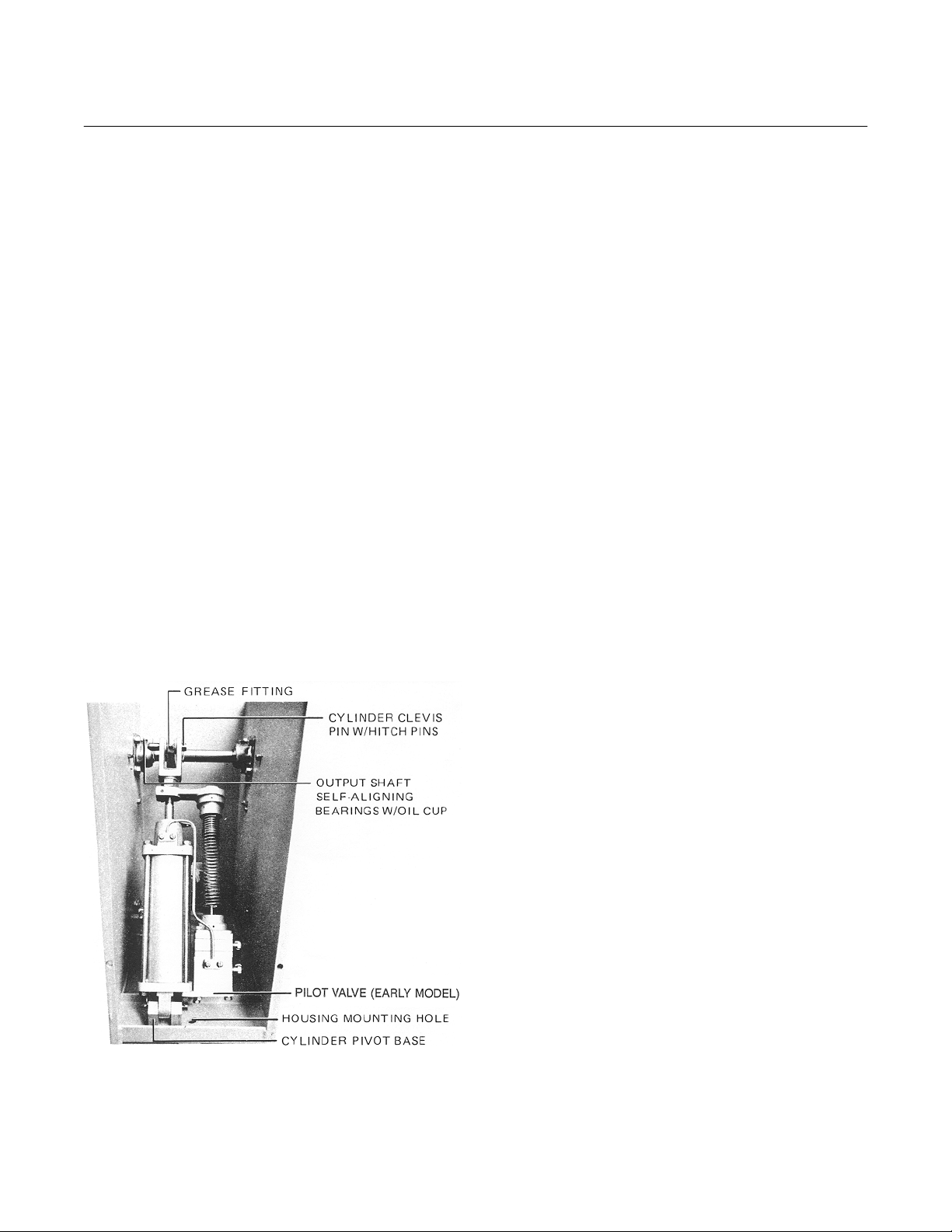
1. Pull one top hitch pin (Figure 3-1) and
the cylinder clevis pin (Figure 3-3).
NOTE
For the characterized unit, it will be
necessary to unhook the feedback
screw swivel from the feedback lever.
2. Swing the cylinder outward through the
front opening of the stand assembly.
b. Lubrication
1. Using a grease gun, periodically lubricate the fitting (Figure 3-3) on the top
end of the cylinder with moly disulfide
grease.
2. Periodically fill the oil cups on the two
self-aligning output shaft bearings with
SAE No. 10 oil.
3. At regular intervals, apply a few drops
of SAE No. 30 oil to both the power
take-off clevis pin and the mounting
pivot pin.
4. Occasionally oil the mechanical linkage
between the power positioner and the
controlled element.
NOTE
The cam follower roller and the feedback lever needle bearings are prelubed and sealed at the factory and thus
require no additional maintenance.
If required, the cylinder assembly can
be completely removed from the stand
assembly.
(a) Disconnect all air tubes from
cylinder.
(b) Pull one hitch pin and cylinder pin
at both ends of the cylinder.
NOTE
The characterized unit will also require
that the feedback lever be unhooked.
Routine maintenance includes periodic lubrication, draining, and cleaning the air filter, the pilot valve stem, and sleeve. Other
maintenance will be required only when the
positioner fails to operate satisfactorily.
Refer to the troubleshooting procedure in
paragraph e.
Rosemount Analytical Inc. A Division of Emerson Process Management Maintenance 5-1
c. Air Supply Filter (P/N 771B920)
The air supply filter should be drained as
necessary and never be allowed to become
over one-half full of condensation.
Disposable filter elements within the filter
should be inspected occasionally and replaced if necessary. New filter elements are
available from the factory in quantities of ten
per box, P/N 6292A98H01.
d. Cleaning Pilot Valve Sleeve and Stem
When clean and dry compressed air is used
and the positioner is operated in a normal
manner, the sleeve and stem should be removed from the pilot valve assembly,
cleaned, and inspected once every six
months. More frequent cleaning and inspection may be required if the condition of
the air is poor or if operating conditions are
severe.
Page 22

Instruction Manual
IB-106-322N Original Issue
June 2000
A sticking stem will cause sluggish piston
response during control signal changes. A
worn stem will cause power air to continuously blow through the exhaust ports in the
pilot valve body.
Use the following procedure for cleaning
and inspecting the pilot valve:
1. Shut off the compressed air supply to
the pilot valve assembly.
2. Reduce the control signal to zero.
3. Remove the pilot valve stem and
sleeve as follows:
Hagan 2-1/2 x 5 and 4 x 5
Do not use any abrasives or sharp
tools to clean stem and sleeve.
(e) Check the stem for straightness by
rolling it on a flat surface. If not
perfectly straight, it must be
replaced.
NOTE
Both the stem and the sleeve must be
replaced together as a complete
assembly.
NOTE
The pilot valve stem and sleeve can be
removed without disconnecting the
cylinder from the cylinder lever, or the
cylinder can be disconnected at the
cylinder lever and laid back inside
stand housing. The characterized unit
will require the lower end of the range
spring to be slid off the pilot valve
spring post.
(a) Unscrew sleeve retainer (18,
Figure 5-1).
(b) Remove bottom loading spring (17)
and bottom stem seat (16).
Be careful not to lose stem, bottom
stem seat, and bottom loading spring.
(c) Allow the stem to fall from pilot
valve assembly.
Be careful that the stem does not fall
on a hard surface. If the stem will not
fall, use the special cap screw fixture
to remove the sleeve and stem assembly.
(d) Wash the stem and sleeve with
solvent. Dry the sleeve with compressed air and wipe off the stem
with a clean cloth.
(f) Check that o-rings on the stem
and sleeve assembly are in good
condition. Install new o-rings if
necessary.
(g) Insert the stem into the bore of the
sleeve.
NOTE
Since the stem is symmetrical, it may
be installed with either end toward the
bottom of the sleeve.
(h) Install the sleeve in the pilot valve
assembly using the special cap
screw fixture.
(i) Replace the pilot valve bottom
stem seat (16, Figure 5-1), bottom
loading spring (17), and sleeve
retainer (18).
(j) Tighten the sleeve retainer until it
contacts the bottom of the sleeve.
(k) Turn on the air supply pressure
and reapply the control signal. The
power positioner is now ready for
operation.
e. Troubleshooting
The four most common causes of unsatisfactory operation of the Model PP075T
power positioner are listed below. Check if
any of these conditions exist and correct
them before removing the positioner from
service.
5-2 Maintenance Rosemount Analytical Inc. A Division of Emerson Process Management
Page 23

Hagan 2-1/2 x 5 and 4 x 5
5
2
1
(NOTE 1)
3
4
EXHAUST PORT
(1 OF 2)
12
Instruction Manual
IB-106-322N Original Issue
June 2000
PORT TO
CYLINDER TOP (*)
SPRING POST
7
INPUT SIGNAL
PORT (*)
9
PORT TO
CYLINDER BOTTOM (*)
POWER
5
6
AIR
SUPPLY
PORT (*)
14
13
1. Socket Head Cap Screw
2. Rubber Boot
3. Top Spring Retainer,
15
Standard
4. Top Loading Spring
5. Top Diaphragm Seat
16
6. Top Diaphragm
7. Center Block
8. Center Diaphragm Post
8
17
9. Bottom Diaphragm
10. Bottom Diaphragm Seat
11. Top Stem Seat
18
12. Valve Body
13. O-rings (4)
14. Sleeve
15. Stem
16. Bottom Stem Seat
10
11
685010
17. Bottom Loading Spring
18. Sleeve Retainer
NOTE 1: 2-1/2 X 5 POWER POSITIONERS USING AN EPT REQUIRE A MODIFIED TOP SPRING RETAINER AND A
TOP DIAPHRAGM COVER IN PLACE OF ITEM (3). IN THE STANDARD PILOT VALVE ASSEMBLY A TOP
DIAPHRAGM COVER IS NOT USED.
NOTE 2: AN ASTERISK (*) INDICATES A 1/8 NPT TAPPED PORT.
Figure 5-1. Pilot Valve Assembly - Exploded View
Rosemount Analytical Inc. A Division of Emerson Process Management Maintenance 5-3
Page 24

Instruction Manual
IB-106-322N Original Issue
June 2000
Hagan 2-1/2 x 5 and 4 x 5
1. Complete loss of air supply or air supply pressure is below normal. Check
for the following conditions:
(a) Air supply shut off at a valve or a
break (or blockage) in piping.
(b) Pressure reducing valves incor-
rectly adjusted. Adjust valves.
(c) Restricted air filter elements. Blow
down all filters.
2. Plugged air signal line. Check that all
lines are clean and free of foreign
material.
3. Leaks in air signal lines. Apply soap
suds on each connection and check for
leaks.
4. Excessive friction at mounting pivot,
take-off clevis, and associated mechanical linkage. Check that these
points are well oiled and not binding.
If none of these causes of trouble are
found, refer to the troubleshooting
chart (Table 5-1).
f. Replacement of Pilot Valve Diaphragms
1. General. Diaphragms (6 and 9, Figure
5-1) in the pilot valve assembly must
be replaced if they are soft and
spongy, hard and brittle, or broken. A
broken diaphragm shows up as erratic
operation of the power positioner with
piston not moving to upper limit when
the maximum signal is applied to pilot
valve. If the break is large, considerable signal air will be noticed leaking
continuously from pilot valve assembly.
2. Procedure. Use the following procedure when inspecting and replacing
diaphragms.
(a) Shut off air supply.
(b) Reduce control (input) signal to
positioner to zero and disconnect
input signal line at pilot valve
assembly.
(c) Disconnect calibration spring from
top diaphragm seat (5) spring post.
(d) Remove socket head cap screws
(1). Remove items (2) through (11)
as an assembled unit.
(e) Remove top spring retainer (3) with
attached rubber boot (2).
(f) Remove top loading spring (4).
NOTE
Top stem seat (11) unthreads from top
diaphragm seat (5), which allows both
diaphragms (6 and 9) to be removed.
(g) Hold top diaphragm seat (5) sta-
tionary by placing a box wrench on
the flats of seat. Unthread top stem
seat (11) from top diaphragm seat
(5).
Excessive clamping pressure produced by exceeding torque valve will
damage diaphragms. Do not exceed
specified torque valves.
(h) Replace diaphragms if broken, hard
and brittle, or soft and spongy. Reassemble diaphragm assembly with
TM
Loctite
stem seat (11). Torque assembly to
1 to 1.5 ft-lbs (1 to 2 N·m).
(i) Reassemble items (1) through (11)
to valve body (12). Only tighten
screws (1) by hand at this time.
(j) Apply and maintain 10 psi (69 kPa)
air pressure between diaphragms
through signal input port.
(k) Turn screws (1) alternately and in
steps to a torque of 2 ft-lbs
(3 N·m).
(l) Remove input signal air pressure.
(m) Turn screws (1) alternately and in
steps to a torque of 4 ft-lbs
(5 N·m).
(n) Connect the calibration spring to
spring post.
(o) Remove the 10 psi (69 kPa) line
and reconnect the control signal
line to pilot valve assembly. Turn
on air supply pressure. The power
positioner is now ready for
operation.
sealant on threads of top
5-4 Maintenance Rosemount Analytical Inc. A Division of Emerson Process Management
Page 25

Hagan 2-1/2 x 5 and 4 x 5
5
Table 5-1. Troubleshooting Chart
Unless otherwise indicated, item numbers are in reference to Figure 5-2.
Symptom Cause Solution
1. Erratic operation along with one of
the following:
Instruction Manual
IB-106-322N Original Issue
June 2000
NOTE
a. Piston moves in a jerky manner. a. Sticky material on inside of
cylinder wall.
b. Piston fails to move to desired
position quickly when signal
changes.
c. Power air continuously blows
through exhaust ports of pilot
valve assembly.
2. Piston does not travel full stroke
when maximum signal is applied
and one of the following symptoms
is present:
a. No other symptoms. a. Too few active coils in cali-
b. Signal air continuously leaking
from exhaust ports of pilot valve
assembly (27).
c. Power air blows continuously
through exhaust ports of pilot
valve assembly (27).
3. Piston does not return to bottom of
cylinder when signal is zero and one
of the following symptoms is
present:
b. Pilot valve stem (15, Figure
5-1) sticking due to gummy
deposits.
c. Pilot valve stem (15, Figure
5-1) excessively worn.
bration spring (8).
b. Broken diaphragm in pilot
valve assembly.
c. Piston cups (22) worn. c. Replace both piston cups.
a. Clean cylinder walls.
b. Clean stem and sleeve.
c. Replace stem and sleeve.
a. Increase number of active
coils in spring.
b. Replace broken diaphragm.
a. No other symptoms. a. Zero adjustment incorrect. a. Recalibrate unit.
b. Power air leaking past piston
rod (5) at seal retainer (11).
c. Power air continuously blows
out of exhaust ports of pilot
valve assembly (27).
Rosemount Analytical Inc. A Division of Emerson Process Management Maintenance 5-5
b. Piston rod seal (12) worn. b. Replace piston rod seal.
c. Piston cups (22) worn. c. Replace both piston cups.
Page 26

Instruction Manual
IB-106-322N Original Issue
June 2000
Hagan 2-1/2 x 5 and 4 x 5
9
1
2
12
15
3
4
5
17
6
10
11
13
14
16
17
24
18
25
19
20
26
16
22
21
20
23
16
727006
1. Retaining Ring
2. Clevis Pin
3. Clevis
4. Locknut
5. Piston Rod
6. Positioner Arm
7. Clamping Screw
8. Calibration Spring
7
8
9. Cap Screw
10. Lockwasher
11. Seal Retainer
12. Seal
13. Hex Nut
14. Lockwasher
15. Top Head Assembly
16. Elbow Fitting
21
27
22
3016
29
28
17. Cylinder Head Gasket
18. Top Tubing
19. Cylinder
20. Garter Spring
21. Piston Cup Follower
22. Piston Cup
23. Bottom Tubing
24. Washer
25. Elastic Stop Nut
26. Bottom Cylinder Head
27. Pilot Valve Assembly
28. Tie-Rod
29. Hex Head Cap Screw
(4 x 5 Only)
30. Lockwasher
(4 x 5 Only)
Figure 5-2. Cylinder Assembly - Exploded View
5-6 Maintenance Rosemount Analytical Inc. A Division of Emerson Process Management
Page 27

Hagan 2-1/2 x 5 and 4 x 5
5
Instruction Manual
IB-106-322N Original Issue
June 2000
g. Repairs to Cylinder Assembly
1. Replacement of Piston Rod Seal. Excessive air leakage from the top head
assembly (15, Figure 5-2) past the
piston rod (5) indicates that the silicone
seal (12) is worn and must be replaced. To replace piston rod seal proceed as follows:
NOTE
Loosening of clamp screw and removal of feedback arm applies to noncharacterized unit only.
(a) Move piston to bottom of cylinder
by reducing control signal to zero.
Then shut off air supply.
(b) Disconnect linkage at clevis (3).
(c) Mark the location of positioner arm
(6) on piston rod (5). Disconnect
lower end of calibration spring (8)
from pilot valve spring post.
(i) Before installing new seal, remove
tape installed in step g. Retape
threads in opposite direction. Tape
should be overlapped with raised,
sharp edges facing downward so
they will not scratch seal as it is
pulled down piston rod. Tape
should also be lubricated with a
light coating of McLube
TM
MOS2-
200 grease.
(j) Install a new seal after lubricating it
with McLube
TM
MOS2-200 grease.
(k) Reassemble power positioner us-
ing preceding steps in reverse order. Clevis and arm must be
properly aligned and located. Use
the mark made in step (c) when
reassembling arm (6, Figure 5-2)
on standard units.
(l) After reassembling unit, perform
steps in paragraph 3-1, Calibration
Procedures. The positioner will
then be ready for operation.
(d) Loosen clamping screw (7) in arm
(6).
(e) Hold clevis and loosen locknut (4)
with a wrench. Unscrew clevis and
locknut, and remove the arm from
the piston rod.
(f) Unscrew cap screws (9), and re-
move lockwasher (10) and seal
retainer (11) to expose seal (12).
(g) In order to ease removal of seal,
place one layer of plastic electricaltype tape over piston rod threads.
Start tape at outer end of piston
rod and overlap it with raised
edges facing the same direction
the seal is to be removed. The
tape should also be lubricated with
a coating of McLube
TM
MOS2-200
grease.
(h) Slip seal off piston rod.
2. Replacement of Piston Cups. If the
piston moves in a jerky manner, it is
usually an indication of an accumulation of sticky material on the inside
walls of the cylinder (19). For the positioner to operate properly, the cylinder
walls must be clean.
If graphite-impregnated teflon piston
cups (22) wear to the extent that air
leaks past the piston, they should be
replaced. This is indicated by power air
blowing continuously through the exhaust openings of the pilot valve.
Before cleaning the cylinder walls or
replacing the piston cups, make sure
there is no problem in the control system. Both standard and on/off units can
operate like there is a piston cup problem when their control systems are
dirty. Before replacing piston cups, follow cleaning procedures in paragraph
Rosemount Analytical Inc. A Division of Emerson Process Management Maintenance 5-7
Page 28

Instruction Manual
IB-106-322N Original Issue
June 2000
5-1d. If this does not solve the problem, proceed as follows:
(a) Shut off all air supply.
(b) Disconnect power and control air
supply lines to pilot valve assembly
(27). Disconnect mechanical linkage at clevis (3).
(c) Remove pivot pin through bottom
cylinder head (26) and place positioner on a work bench.
(d) Disconnect calibration spring (8,
Figure 5-2) from pilot valve.
(e) Disconnect tubing (18) from pilot
valve.
(f) Remove hex nuts (13), lockwash-
ers (14), and four steel tie-rods
(28).
(g) Remove pilot valve assembly (27)
and bottom cylinder head (26) as
an assembly.
(h) Invert the remaining positioner as-
sembly and support it vertically by
clamping clevis (3) in a vise.
(i) Remove cylinder (19) from piston
assembly by slowly turning the
cylinder clockwise while pulling it
upward away from top head assembly (15).
(j) Clean out bore of cylinder with a
cloth soaked in a solvent. Do not
scrape with sharp tools or use
abrasive materials such as emery
cloth.
(k) Inspect piston cups (22). If worn,
creased, or scratched, they must
both be replaced.
(l) If piston cups require replacement,
remove elastic stop nut (25) and
washer (24) from rod (5). Two piston cup followers (21) and piston
cups may then be slipped off the
end of the piston rod.
Hagan 2-1/2 x 5 and 4 x 5
Be careful that piston cups are not
creased or scratched during assembly. Use piston insertion sleeve, P/N
4847B54H01. Damaged piston cups
will impair positioner performance.
(m) Reassemble piston assembly and
insert it into cylinder in the following manner:
1 Assemble parts of piston on
end of piston rod except outer
garter spring (20) and outer
piston cup.
2 Turn elastic stop nut (25) until
only finger tight.
3 Check that gasket (17) is in
place at top head assembly
and then slip cylinder down
over the piston assembly until
washer (24) is about 1/4 in.
(6 mm) from end of cylinder.
4 Remove elastic stop nut (25),
washer (24), and outer piston
cup follower (21). Install outer
piston cup (22), outer piston
cup follower (21) and garter
spring (20); reassemble entire
piston. Tighten elastic stop
nut (25).
5 Hold top head assembly and
pull cylinder back over piston
assembly until piston is approximately half way into
cylinder.
(n) Remove positioner from vise. Pull
top head assembly along piston
rod until it hits the end of the
cylinder.
(o) Reassemble positioner by install-
ing pilot valve and bottom cylinder
head at lower end of cylinder and
installing tie-rods, lockwashers,
and nuts.
(p) Connect tubing (18) to pilot valve
assembly.
5-8 Maintenance Rosemount Analytical Inc. A Division of Emerson Process Management
Page 29

Hagan 2-1/2 x 5 and 4 x 5
5
Instruction Manual
IB-106-322N Original Issue
June 2000
(q) Connect calibration spring to pilot
valve assembly.
(r) Mount positioner and connect link-
age to clevis. Connect power air
supply and control air signal lines
to control system. Open control
signal air.
(s) Turn on power air supply pressure.
The positioner is now ready for
operation.
h. Cam Manufacture for Special Function
Applications
Field shaping of a cam from a cam blank
may be required in some applications where
the process-to-input signal relationship does
not conform to the standard available cam
shapes. The following procedure is recommended for developing a non-standard
cam.
1. Preliminary Steps.
(a) Determine the minimum and
maximum positions of the final
control element (e.g., valve or
damper) being operated by the
power positioner.
(b) Adjust the mechanical linkage so
the power positioner travels
through its full stroke while the
element being positioned travels
from its required minimum to
maximum position.
(c) Set the power positioner stroke, as
directed in paragraph 3-1, Calibration Procedures, so the positioner
reaches the bottom of its stroke
when the input signal is zero.
When the input signal is maximum,
adjust the positioner so the piston
just reaches the top of its stroke.
30 psig (0 to 116.9 kPa) input signal, a 6 psig (41.4 kPa) increment].
(b) Plot the curve X (Figure 5-3) from
the data obtained from the previous step.
(c) In this example, the desired char-
acteristic (curve Y, Figure 5-3) has
been chosen to be a straight line.
Curve Y is plotted between minimum and maximum values on
curve X. A characteristic other than
a straight line may be plotted in the
same fashion on Curve Y, if
desired.
(d) At each 20 percent of input signal
(Figure 5-3), project a horizontal
line to straight line curve Y. Project
vertically downward from the intersection of the horizontal line and
curve Y to curve X. From the intersection of the vertical projection
and curve X, project a horizontal
line to the right. Read and tabulate
the actual percent of cam rotation,
indicated on the right margin, versus the percent of input signal as
shown in the example table (Table
5-2).
(e) Using the blank scale layout (Fig-
ure 5-4) and the information from
Table 5-2, plot the cam roller centers on the scale (Figure 5-5).
(f) Using a compass set to 0.5 in.
(12.7 mm) diameter, draw the cam
roller circles with the plotted points
as centers.
(g) Carefully draw a smooth curve
through the tangent points on the
inner side of the circles.
(h) Cut out the paper cam leaving the
cam contour and the two mounting
holes.
2. Procedure.
(a) Determine the percent of process
(e.g., flow) at each 20 percent increment of input signal [e.g., 0 to
Rosemount Analytical Inc. A Division of Emerson Process Management Maintenance 5-9
3. Carefully line up the two mounting
holes and cement the cutout to the
blank cam section of the square root
cam for final shaping using coarse and
fine files.
Page 30

Instruction Manual
IB-106-322N Original Issue
June 2000
Table 5-2. Tabulation of Percent Input Signal vs. Percent Cam Rotation
Example Developed Table
Input Signal % Cam Rotation % Input Signal % Cam Rotation %
Hagan 2-1/2 x 5 and 4 x 5
20
40
60
80
100
0
25
45
70
100
0
9
0
20
40
60
80
100
Curve X represents the process versus the input signal relationship determined from field data.
Curve Y represents the desired process versus the input signal relationship. This relationship is maintained by the operation
of the Power Positioner after the cam is properly shaped.
(*) These values represent the radial location of the center points of the cam roller and are used to
plot the cam curve shown in Figure 5-3.
Figure 5-3. Example of Desired and Actual Process and Input Signal Relationship
5-10 Maintenance Rosemount Analytical Inc. A Division of Emerson Process Management
Page 31

Hagan 2-1/2 x 5 and 4 x 5
5
Instruction Manual
IB-106-322N Original Issue
June 2000
Figure 5-4. Blank Scale Layouts for Developing Cam Contour
Figure 5-5. Example of Field Shaped Cam Plot
Rosemount Analytical Inc. A Division of Emerson Process Management Maintenance 5-11
Page 32

Instruction Manual
IB-106-322N Original Issue
June 2000
Hagan 2-1/2 x 5 and 4 x 5
5-12 Maintenance Rosemount Analytical Inc. A Division of Emerson Process Management
Page 33

Hagan 2-1/2 x 5 and 4 x 5
6
RETURN OF MATERIAL
Instruction Manual
IB-106-322N Original Issue
June 2000
SECTION 6
6-1 If factory repair of defective equipment is re-
quired, proceed as follows:
a. Secure a return authorization number from
a Rosemount Analytical Sales Office or
Representative before returning the equipment. Equipment must be returned with
complete identification in accordance with
Rosemount instructions or it will not be
accepted.
In no event will Rosemount be responsible
for equipment returned without proper
authorization and identification.
b. Carefully pack defective unit in a sturdy box
with sufficient shock absorbing material to
ensure no additional damage will occur
during shipping.
c. In a cover letter, describe completely:
1. The symptoms from which it was determined that the equipment is faulty.
2. The environment in which the equipment was operating (housing, weather,
vibration, dust, etc.).
3. Site from which equipment was removed.
5. Complete shipping instructions for return of equipment.
6. Reference the return authorization
number.
d. Enclose a cover letter and purchase order
and ship the defective equipment according
to instructions provided in Rosemount Return Authorization, prepaid, to:
Rosemount Analytical Inc.
RMR Department
1201 North Main Street
Orrville, Ohio 44667
If warranty service is requested, the defective unit will be carefully inspected and
tested at the factory. If failure was due to
conditions listed in the standard Rosemount
warranty, the defective unit will be repaired
or replaced at Rosemount's option, and an
operating unit will be returned to the customer in accordance with shipping instructions furnished in the cover letter.
For equipment no longer under warranty,
the equipment will be repaired at the factory
and returned as directed by the purchase
order and shipping instructions.
4. Whether warranty or nonwarranty
service is requested.
Rosemount Analytical Inc. A Division of Emerson Process Management Return of Material 6-1
Page 34

Instruction Manual
IB-106-322N Original Issue
June 2000
Hagan 2-1/2 x 5 and 4 x 5
6-2 Return of Material Rosemount Analytical Inc. A Division of Emerson Process Management
Page 35

Hagan 2-1/2 x 5 and 4 x 5
7
ASSEMBLY DRAWINGS AND PARTS LISTINGS
Figure 7-1. Model PP075T Power Positioner (16 Sheets)
Figure 7-2. 4 x 5 Power Positioner (2 Sheets)
Figure 7-3. 2-1/2 x 5 Power Positioner (2 Sheets)
Figure 7-4. Air Supply Filter
Instruction Manual
IB-106-322N Original Issue
June 2000
SECTION 7
Figure 7-5. Feedback Lever on Roller Assembly
Figure 7-6. Main Shaft Assembly
Rosemount Analytical Inc. A Division of Emerson Process Management Drawings and Schematics 7-1
Page 36

Instruction Manual
IB-106-322N Original Issue
June 2000
Hagan 2-1/2 x 5 and 4 x 5
Figure 7-1. Model PP075T Power Positioner (Sheet 1 of 16)
7-2 Drawings and Schematics Rosemount Analytical Inc. A Division of Emerson Process Management
Page 37

Hagan 2-1/2 x 5 and 4 x 5
7
Instruction Manual
IB-106-322N Original Issue
June 2000
Figure 7-1. Model PP075T Power Positioner (Sheet 2 of 16)
Rosemount Analytical Inc. A Division of Emerson Process Management Drawings and Schematics 7-3
Page 38

Instruction Manual
IB-106-322N Original Issue
June 2000
Hagan 2-1/2 x 5 and 4 x 5
NOTE: SEE CONVERSION CHART DWG. 1547B90 FOR LISTED ASSY. VARIATIONS.
Figure 7-1. Model PP075T Power Positioner (Sheet 3 of 16)
7-4 Drawings and Schematics Rosemount Analytical Inc. A Division of Emerson Process Management
Page 39

Hagan 2-1/2 x 5 and 4 x 5
7
Instruction Manual
IB-106-322N Original Issue
June 2000
Figure 7-1. Model PP075T Power Positioner (Sheet 4 of 16)
Rosemount Analytical Inc. A Division of Emerson Process Management Drawings and Schematics 7-5
Page 40

Instruction Manual
IB-106-322N Original Issue
June 2000
Hagan 2-1/2 x 5 and 4 x 5
Figure 7-1. Model PP075T Power Positioner (Sheet 5 of 16)
7-6 Drawings and Schematics Rosemount Analytical Inc. A Division of Emerson Process Management
Page 41

Hagan 2-1/2 x 5 and 4 x 5
7
Instruction Manual
IB-106-322N Original Issue
June 2000
Figure 7-1. Model PP075T Power Positioner (Sheet 6 of 16)
Rosemount Analytical Inc. A Division of Emerson Process Management Drawings and Schematics 7-7
Page 42

Instruction Manual
IB-106-322N Original Issue
June 2000
Hagan 2-1/2 x 5 and 4 x 5
Figure 7-1. Model PP075T Power Positioner (Sheet 7 of 16)
7-8 Drawings and Schematics Rosemount Analytical Inc. A Division of Emerson Process Management
Page 43

Hagan 2-1/2 x 5 and 4 x 5
7
Instruction Manual
IB-106-322N Original Issue
June 2000
Figure 7-1. Model PP075T Power Positioner (Sheet 8 of 16)
Rosemount Analytical Inc. A Division of Emerson Process Management Drawings and Schematics 7-9
Page 44

Instruction Manual
IB-106-322N Original Issue
June 2000
Hagan 2-1/2 x 5 and 4 x 5
Figure 7-1. Model PP075T Power Positioner (Sheet 9 of 16)
7-10 Drawings and Schematics Rosemount Analytical Inc. A Division of Emerson Process Management
Page 45

Hagan 2-1/2 x 5 and 4 x 5
7
Instruction Manual
IB-106-322N Original Issue
June 2000
Figure 7-1. Model PP075T Power Positioner (Sheet 10 of 16)
Rosemount Analytical Inc. A Division of Emerson Process Management Drawings and Schematics 7-11
Page 46

Instruction Manual
IB-106-322N Original Issue
June 2000
Hagan 2-1/2 x 5 and 4 x 5
Figure 7-1. Model PP075T Power Positioner (Sheet 11 of 16)
7-12 Drawings and Schematics Rosemount Analytical Inc. A Division of Emerson Process Management
Page 47

Hagan 2-1/2 x 5 and 4 x 5
7
Instruction Manual
IB-106-322N Original Issue
June 2000
Figure 7-1. Model PP075T Power Positioner (Sheet 12 of 16)
Rosemount Analytical Inc. A Division of Emerson Process Management Drawings and Schematics 7-13
Page 48

Instruction Manual
IB-106-322N Original Issue
June 2000
Hagan 2-1/2 x 5 and 4 x 5
Figure 7-1. Model PP075T Power Positioner (Sheet 13 of 16)
7-14 Drawings and Schematics Rosemount Analytical Inc. A Division of Emerson Process Management
Page 49

Hagan 2-1/2 x 5 and 4 x 5
7
Instruction Manual
IB-106-322N Original Issue
June 2000
Figure 7-1. Model PP075T Power Positioner (Sheet 14 of 16)
Rosemount Analytical Inc. A Division of Emerson Process Management Drawings and Schematics 7-15
Page 50

Instruction Manual
IB-106-322N Original Issue
June 2000
Hagan 2-1/2 x 5 and 4 x 5
Figure 7-1. Model PP075T Power Positioner (Sheet 15 of 16)
7-16 Drawings and Schematics Rosemount Analytical Inc. A Division of Emerson Process Management
Page 51

Hagan 2-1/2 x 5 and 4 x 5
7
Instruction Manual
IB-106-322N Original Issue
June 2000
Figure 7-1. Model PP075T Power Positioner (Sheet 16 of 16)
Rosemount Analytical Inc. A Division of Emerson Process Management Drawings and Schematics 7-17
Page 52

Instruction Manual
IB-106-322N Original Issue
June 2000
Hagan 2-1/2 x 5 and 4 x 5
Figure 7-2. 4 X 5 Power Positioner (Sheet 1 of 2)
7-18 Drawings and Schematics Rosemount Analytical Inc. A Division of Emerson Process Management
Page 53

Hagan 2-1/2 x 5 and 4 x 5
7
Instruction Manual
IB-106-322N Original Issue
June 2000
Figure 7-2. 4 X 5 Power Positioner (Sheet 2 of 2)
Rosemount Analytical Inc. A Division of Emerson Process Management Drawings and Schematics 7-19
Page 54

Instruction Manual
IB-106-322N Original Issue
June 2000
Hagan 2-1/2 x 5 and 4 x 5
Figure 7-3. 2-1/2 x 5 Power Positioner (Sheet 1 of 2)
7-20 Drawings and Schematics Rosemount Analytical Inc. A Division of Emerson Process Management
Page 55

Hagan 2-1/2 x 5 and 4 x 5
7
Instruction Manual
IB-106-322N Original Issue
June 2000
NOTE: FIGURE BASED ON ROSEMOUNT
DWG. NO. 3D39395.
Figure 7-3. 2-1/2 X 5 Power Positioner (Sheet 2 of 2)
Rosemount Analytical Inc. A Division of Emerson Process Management Drawings and Schematics 7-21
Page 56

Instruction Manual
IB-106-322N Original Issue
June 2000
Hagan 2-1/2 x 5 and 4 x 5
Figure 7-4. Air Supply Filter
7-22 Drawings and Schematics Rosemount Analytical Inc. A Division of Emerson Process Management
Page 57

Hagan 2-1/2 x 5 and 4 x 5
7
Instruction Manual
IB-106-322N Original Issue
June 2000
Figure 7-5. Feedback Lever on Roller Assembly
Rosemount Analytical Inc. A Division of Emerson Process Management Drawings and Schematics 7-23
Page 58

Instruction Manual
IB-106-322N Original Issue
June 2000
Hagan 2-1/2 x 5 and 4 x 5
Figure 7-6. Main Shaft Assembly
7-24 Drawings and Schematics Rosemount Analytical Inc. A Division of Emerson Process Management
Page 59

WARRANTY
Goods and part(s) (excluding consumables) manufactured by Seller are warranted to be free from
defects in workmanship and material under normal use and service for a period of twelve (12)
months from the date of shipment by Seller. Consumables, glass electrodes, membranes, liquid
junctions, electrolyte, o-rings, etc., are warranted to be free from defects in workmanship and
material under normal use and service for a period of ninety (90) days from date of shipment by
Seller. Goods, part(s) and consumables proven by Seller to be defective in workmanship and/or
material shall be replaced or repaired, free of charge, F.O.B. Seller's factory provided that the
goods, part(s) or consumables are returned to Seller's designated factory, transportation charges
prepaid, within the twelve (12) month period of warranty in the case of goods and part(s), and in
the case of consumables, within the ninety (90) day period of warranty. This warranty shall be in
effect for replacement or repaired goods, part(s) and the remaining portion of the ninety (90) day
warranty in the case of consumables. A defect in goods, part(s) and consumables of the commercial unit shall not operate to condemn such commercial unit when such goods, part(s) and
consumables are capable of being renewed, repaired or replaced.
The Seller shall not be liable to the Buyer, or to any other person, for the loss or damage directly
or indirectly, arising from the use of the equipment or goods, from breach of any warranty, or from
any other cause. All other warranties, expressed or implied are hereby excluded.
IN CONSIDERATION OF THE HEREIN STATED PURCHASE PRICE OF THE GOODS,
SELLER GRANTS ONLY THE ABOVE STATED EXPRESS WARRANTY. NO OTHER WARRANTIES ARE GRANTED INCLUDING, BUT NOT LIMITED TO, EXPRESS AND IMPLIED
WARRANTIES OR MERCHANTABILITY AND FITNESS FOR A PARTICULAR PURPOSE.
Limitations of Remedy. SELLER SHALL NOT BE LIABLE FOR DAMAGES CAUSED BY DELAY IN PERFORMANCE. THE SOLE AND EXCLUSIVE REMEDY FOR BREACH OF WARRANTY SHALL BE LIMITED TO REPAIR OR REPLACEMENT UNDER THE STANDARD
WARRANTY CLAUSE. IN NO CASE, REGARDLESS OF THE FORM OF THE CAUSE OF ACTION, SHALL SELLER'S LIABILITY EXCEED THE PRICE TO BUYER OF THE SPECIFIC
GOODS MANUFACTURED BY SELLER GIVING RISE TO THE CAUSE OF ACTION. BUYER
AGREES THAT IN NO EVENT SHALL SELLER'S LIABILITY EXTEND TO INCLUDE INCIDENTAL OR CONSEQUENTIAL DAMAGES. CONSEQUENTIAL DAMAGES SHALL INCLUDE, BUT
ARE NOT LIMITED TO, LOSS OF ANTICIPATED PROFITS, LOSS OF USE, LOSS OF REVENUE, COST OF CAPITAL AND DAMAGE OR LOSS OF OTHER PROPERTY OR EQUIPMENT.
IN NO EVENT SHALL SELLER BE OBLIGATED TO INDEMNIFY BUYER IN ANY MANNER
NOR SHALL SELLER BE LIABLE FOR PROPERTY DAMAGE AND/OR THIRD PARTY CLAIMS
COVERED BY UMBRELLA INSURANCE AND/OR INDEMNITY COVERAGE PROVIDED TO
BUYER, ITS ASSIGNS, AND EACH SUCCESSOR INTEREST TO THE GOODS PROVIDED
HEREUNDER.
Force Majeure. Seller shall not be liable for failure to perform due to labor strikes or acts beyond
Seller's direct control.
3352/6-00
Page 60

Instruction Manual
IB-106-322N Original Issue
June 2000
Hagan 2-1/2 x 5 and 4 x 5
Emerson Process Management
Rosemount Analytical Inc.
Process Analytic Division
1201 N. Main St.
Orrville, OH 44667-0901
T (330) 682-9010
F (330) 684-4434
E gas.csc@emersonprocess.com
ASIA - PACIFIC
Fisher-Rosemount
Singapore Private Ltd.
1 Pandan Crescent
Singapore 128461
Republic of Singapore
T 65-777-8211
F 65-777-0947
http://www.processanalytic.com
© Rosemount Analytical Inc. 2001
Fisher-Rosemount GmbH & Co.
Industriestrasse 1
63594 Hasselroth
Germany
T 49-6055-884 0
F 49-6055-884209
EUROPE, MIDDLE EAST, AFRICA
Fisher-Rosemount Ltd.
Heath Place
Bognor Regis
West Sussex PO22 9SH
England
T 44-1243-863121
F 44-1243-845354
LATIN AMERICA
Fisher - Rosemount
Av. das Americas
3333 sala 1004
Rio de Janeiro, RJ
Brazil 22631-003
T 55-21-2431-1882
 Loading...