

Page 1
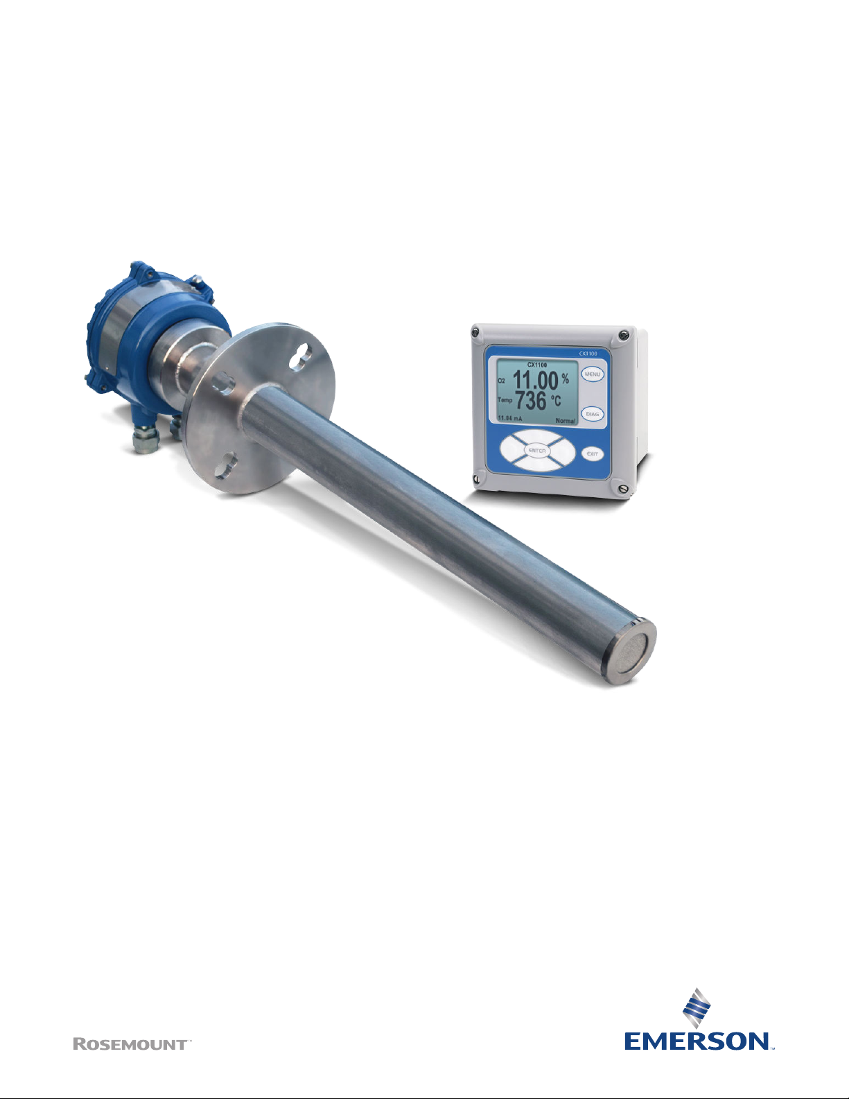
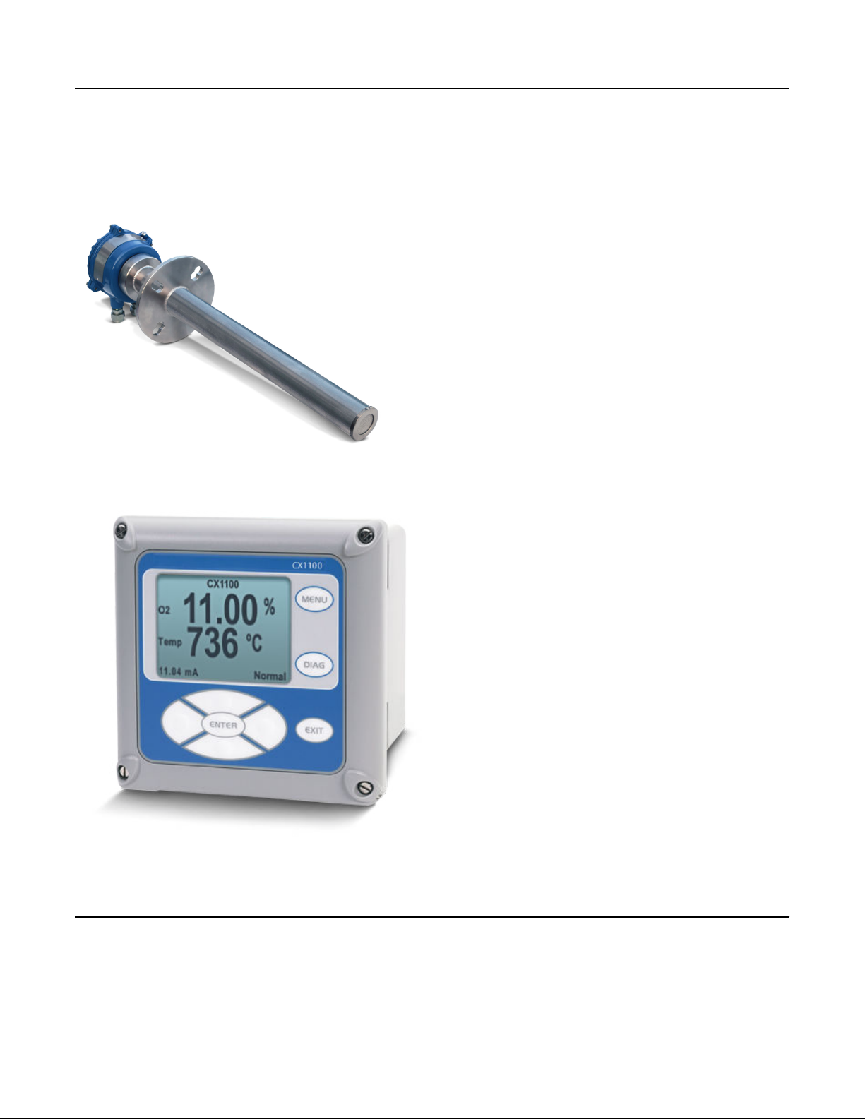
Rosemount™ CX1100
In-Situ Oxygen Transmitter
Product Data Sheet
00813-0100-4110, Rev AA
July 2018
Page 2
Rosemount CX1100
Product benefits
Reliable combustion measurement
July 2018
■ Robust zirconia oxygen sensor provides measurement of furnace exhaust gas critical for boiler trim applications.
■ Good measurement repeatability of 0.1% O2 or 1.0% of reading and multiple probe length options to suit your application needs.
■ Optional remote mounted LCD display and interface for easy
access to process information and simplified maintenance.
CX1100 remote display
Remote display and interface for configuration, calibration,
■
and maintenance without the need for additional tools.
■ Bright, back-lit display and an easy-to-use keypad.
Contents
Product benefits ........................................................................................................................................................... 2
Specifications ............................................................................................................................................................... 4
Product certifications ................................................................................................................................................... 6
Dimensional drawings .................................................................................................................................................. 7
2 www.Emerson.com
Page 3
July 2018
Rosemount CX1100
Rosemount CX1100 In-Situ Oxygen Transmitter ordering information
Model Product description
CX1100 In Situ Oxygen Transmitter
Material
A 304L stainless steel
Probe length
050 1.64 ft. (0.5 m) oxygen probe
100 3.28 ft. (1.0 m) oxygen probe
200 6.56 ft. (2.0 m) oxygen probe
Probe mounting flange
F20 ANSI/DIN: 4.75 in. / 5.71 in. bolt circle, 0.75 in. holes
Transmitter
M7 Remote transmitter with LCD display and interface
M0 Probe only (no transmitter)
Product certification
G6 CSA ordinary location
Probe mounting hardware
N1 New installation plate - ANSI pattern
N2 New installation plate - DIN pattern
Transmitter mounting hardware
T2 Panel mount kit with gasket
T3 2-in. pipe / wall mount kit
Calibration accessories
F1 Calibration gas flowmeter
www.Emerson.com 3
Page 4
Rosemount CX1100
July 2018
Specifications
System Measurement SpecificationsTable 1:
Specification Description
Net O2 range 0 - 23%
Repeatability 0.1% of O2 or 1.0% of reading, whichever is lower
Lowest detectable limit 0.05% O
Process temperature effect Less than 0.3% O2 from 77 to 1292 °F (25 to 700 °C)
System speed of response to calibration gas Initial response in less than 3 seconds, T90 in 10 seconds. Re-
sponse to process gas changes will vary depending on process
gas velocity and particulate loading of the diffuser.
Environmental specifications
ProbeTable 2:
Specification Description
Probe Process wetted materials are 304 stainless steel.
Maximum process temperature 752 °F (400 °C)
2
Probe TerminationsTable 3:
Specification Description
Rosemount™ CX1100 probe ambient temperature limits -4 to 158 °F (-20 to 70 °C)
Remote DisplayTable 4:
Specification Description
Materials Polycarbonate
Ambient temperature limits -4 to 122 °F (-20 to 50 °C)
Installation specifications
ProbeTable 5:
Specification Description
Probe mounting range Vertical or horizontal: 2-in. 150# (4.75 in. (121 mm) bolt circle) and DIN145
Note
Flanges are flat-faced and for mounting only. Flanges are not pressure-rated. A 2.5-in.
diameter hole in the process is required.
Many adapter flanges are available to mate to existing flanges.
Reference air No instrument air required. Ambient air diffuses into the probe passively. Ensure that
ambient air is fresh (20.95% O2).
Calibration Semi-automatic manual gas switching. New calibration values are calculated in the
remote electronics.
Cal gases 0.4% and 8% O2, balance N2 recommended. Instrument air may be used as a high cal
gas, but is not recommended. 100% nitrogen cannot be used as a low cal gas.
4 www.Emerson.com
Page 5

July 2018
Rosemount CX1100
Probe (continued)Table 5:
Specification Description
Calibration gas flow 5 scfh (2.5 l/min) at 15 PSI
Heater electrical power 120/240 Vac, 50/60 Hz, 1.8 A Max
Traditional architecture cable Customer-supplied
Power consumption of probe heater 150 watts max. during initial warm-up
Remote ElectronicsTable 6:
Specification Description
Electrical power 120/240 Vac, 50/60 Hz, 1.8 A Max
Power consumption 150 watts during initial warm-up
Analog output 4-20 mA. Max load 550 Ohms
Alarms relays Two SPDT Form C, epoxy sealed contacts rated 5A, 30 Vdc, 120
Vac, or 230 Vac; user configurable to alarm.
Resistive load: 5A at 28 Vdc or 300 Vac
Inductive load: 1/8 HP at 120/240 Vac
Probe sensing cable 3 twisted pair conductors, 22 ga overall shielded cable to con-
nect the TC, O2, and CJC signals
Heater cable 3 multi conductor 18 ga shielded cable to connect the heater
control signal
Rosemount CX1100 Probe Shipping weight Actual weight
19.68 in. (0.5 m) 19 lb. (8.6 kg) 13.5 lb. (6.1 kg)
39.37 in. (1 m) 23 lb. (10.43 kg) 16.8 lb. (7.6 kg)
78.74 in. (2 m) 30.5 lb. (13.8 kg) 23 lb. (10.43 kg)
Rosemount CX1100 Remote
Transmitter dimensions in
inches (millimeters) Shipping weight Actual weight Part number
6.10 x 6.10 x 5.15 in. (155 x
155 x 131 mm)
Accessory Part number
Calibration flowmeter 771B635H01
Cal gas adaptor kit to mate to existing tubing arrangement 1A98771H07
4 lb. (1.8 kg)_ 3 lb. (1.4 kg) 24490-00
www.Emerson.com 5
Page 6

Rosemount CX1100
July 2018
Product certifications
European Directive information
A copy of the EC Declaration of Conformity can be found at the end of the Quick Start Guide. The most recent revision of the EC
Declaration of Conformity can be found at Emerson.com/Rosemount.
Ordinary location certification
As standard, the transmitter has been examined and tested to determine that the design meets the basic electrical, mechanical,
and fire protection requirements by a nationally recognized test laboratory (NRTL) as accredited by the Federal Occupational Safety
and Health Administration (OSHA).
Installing equipment in North America
The US National Electrical Code (NEC) and the Canadian Electrical Code (CEC) permit the use of Division marked equipment in Zones
and Zone marked equipment in Divisions. The marking must be suitable for the area classification, gas, and temperature class. This
information is clearly defined in the respective codes.
North America
CSA
Certificate: 70172073
Standards: CAN/CSA C22.2 No. 61010-1-12, CAN/CSA C22.2 No. 61010-2-010:15, UL 61010-1 (3rd Edition), UL 61010-2-10 (3rd
Edition), UL 50E (2012), C22.2 No. 94.2-07, IEC 60529:2013 (Edition 2.2)
Markings: Type 4X, IP66
Condition of acceptability:
1. The measuring of net O2 range is limited 0-23%.
2. The equipment shall be installed in accordance with manufacturer's specification by qualified personnel.
3. This equipment is for permanently connection to power source with approved power cord at end installation in accordance with
local codes.
4. The Probe unit of the equipment shall be connected to PE separately at end installation.
5. End installation to provide the means of disconnection from power sources.
6. End installation to comply with the requirement of IP66 and 4X.
6 www.Emerson.com
Page 7

July 2018
Dimensional drawings
Probe Installation DimensionsFigure 1:
Rosemount CX1100
A. M6 x 1 x 25 hex head machine screw (3x)
B. Calibration gas 3/16-in. tube fitting 2.82 liter/min (10 SCFH), 138 kPa (20 psi)
C. M5 x 0.8 x 10 pan head machine screw
D. 1/2 NPT conduit connection (power, signal)
E. Breather port
F. Calibration gas connection
Note
All dimensions are in meters with inches in parentheses.
Removal/InstallationTable 7:
Probe length Removal envelope
.5 m (19.68 in.) 750 mm (30 in.)
1 m (39.37 in.) 1250 mm (49 in.)
3 m (78.74 in.) 2250 mm (89 in.)
www.Emerson.com 7
Page 8

Rosemount CX1100
Mounting FlangeTable 8:
Diameter ANSI DIN
Flange dia 185 mm (7.28 in.)
Hold dia 19.1 mm (.75 in.)
(4) holes eq sp on BC 120.7 mm (4.75 in.) 145 mm (5.71 in.)
July 2018
8 www.Emerson.com
Page 9

July 2018
Rosemount CX1100
Square Weld Plate, ANSI PatternFigure 2:
Square Weld Plate, DIN PatternFigure 3:
www.Emerson.com 9
Page 10

Rosemount CX1100
Panel Mounting DetailsFigure 4:
July 2018
A. Maximum panel thickness 0.375 (9,52)
B. Panel mount gasket
C. 4 X mounting brackets and screws provided
A. 6 x 1/2 in. NPT conduit openings
10 www.Emerson.com
Page 11

July 2018
Wall/Surface Mounting DetailsFigure 5:
A. 4X cover screw
Rosemount CX1100
Pipe Mounting DetailsFigure 6:
A. Front panel
B. 6 x 1/2-in. NPT conduit openings
C. Mounting bracket
D. U-bolts
E. 2-in. pipe supplied by customer
www.Emerson.com 11
Page 12

Rosemount CX1100
00813-0100-4110, Rev AA
Product Data Sheet
July 2018
GLOBAL HEADQUARTERS
Emerson Automation Solutions
6021 Innovation Blvd
Shakopee, MN 55379, USA
+1 800 999 9307 or +1 952 906 8888
+1 952 949 7001
gas.csc@emerson.com
EUROPE
Emerson Automation Solutions
Neuhofstrasse 19a P.O. Box 1046
CH-6340 Baar
Switzerland
+ 41 (0) 41 768 6111
+ 41 (0) 41 768 6300
gas.csc@emerson.com
Linkedin.com/company/Emerson-Automation-Solutions
twitter.com/rosemount_news
Facebook.com/Rosemount
youtube.com/RosemountMeasurement
google.com/+RosemountMeasurement
AnalyticExpert.com
NORTH AMERICA
Rosemount
8200 Market Boulevard
Chanhassen, MN 55317
MIDDLE EAST AND AFRICA
Emerson Automation Solutions
Emerson FZE
Jebel Ali Free Zone
Dubai, United Arab Emirates, P.O. Box
17033
+1 800 999 9307
+1 952 949 7001
gas.csc@emerson.com
+971 4 811 8100
+971 4 886 5465
gas.csc@emerson.com
©
2018 Emerson. All rights reserved.
The Emerson logo is a trademark and service mark of Emerson Electric Co. Rosemount
is a mark of one of the Emerson family of companies. All other marks are the property
of their respective owners.
ASIA-PACIFIC
Emerson Automation Solutions
1 Pandan Crescent
Singapore 128461
Singapore
+65 777 8211
+65 777 0947
gas.csc@emerson.com
 Loading...