

Page 1
Rosemount™ CX1100 In Situ Oxygen
Transmitter
Quick Start Guide
00825-0100-4110, Rev AA
July 2018
Page 2

Essential instructions
EmersonTM designs, manufactures, and tests its products to meet many national and international standards. Because these
instruments are sophisticated technical products, you must properly install, use, and maintain them to ensure they continue to
operate within their normal specifications. The following instructions must be adhered to and integrated into your safety program
when installing, using, and maintaining Emerson products.
• Read all instructions prior to installing, operating, and servicing the product.
• Install equipment as specified in the installation instructions of the appropriate instruction manual and per applicable local
and national codes. Connect all products to the proper electrical and pressure sources.
Symbols
Earth (ground) terminal
Protective conductor terminal
Risk of electrical shock
Refer to reference manual.
Page 3

Contents
Contents
Chapter 1 Install .............................................................................................................................1
1.1 Probe installation .........................................................................................................................1
1.2 Mount remote display ..................................................................................................................4
Chapter 2 Wire .............................................................................................................................. 8
2.1 Installation specifications - interconnect cable .............................................................................8
2.2 Connect the cables ...................................................................................................................... 8
Chapter 3 Startup .........................................................................................................................13
Chapter 4 Calibration ................................................................................................................... 14
4.1 Procedure ..................................................................................................................................14
Appendices and reference
Appendix A Product certifications ...................................................................................................16
A.1 European Directive information ................................................................................................. 16
A.2 Ordinary location certification ................................................................................................... 16
A.3 Installing equipment in North America ...................................................................................... 16
A.4 Rosemount CX1100 In-Situ Oxygen Transmitter ........................................................................16
A.4.1 North America .............................................................................................................16
Quick Start Guide i
Page 4

Contents
ii Rosemount™ CX1100
Page 5

1 Install
WARNING!
Before installing this equipment, read the Essential Instructions at the front of this Quick Start
Guide. Failure to follow safety instructions could result in serious injury or death.
1.1 Probe installation
A weld plate for welding to the flue gas duct can be supplied for new installations.
1. If using the standard square weld plate (Figure 1-2) or an optional flange mounting
plate, weld or bolt the plate onto the duct.
The through hole diameter in the stack or duct wall and refractory material must be
at least 2.5 in. (63.5 mm).
2. Insert probe through the opening in the mounting flange and bolt through the
probe gasket and flange.
Install
For horizontal installations, the breather port must be oriented such that it is facing
downward.
Quick Start Guide 1
Page 6
Install
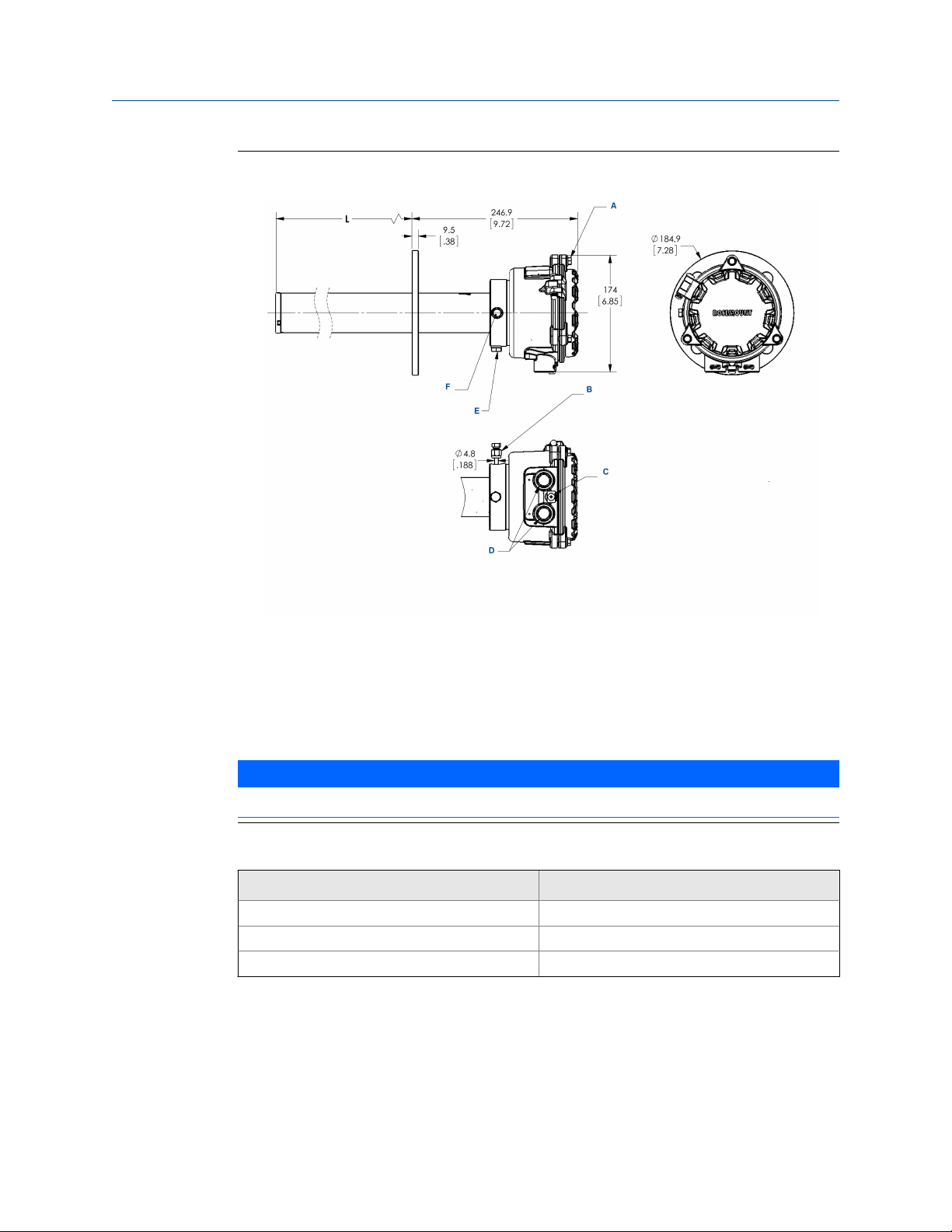
Probe InstallationFigure 1-1:
A. M6 X 1 X 25 hex head machine screw (3X)
B. Calibration gas, 3/16-in. tube fitting, 2.82 liter/min (10 SCFH), 138 kPa (20 psi)
C. M5 X 0.8 x 10 pan head machine screw, ground screw
D. 1/2 NPT conduit connection (power, signal)
E. Breather port
F. Calibration gas connection
NOTICE
All dimensions are in millimeters with inches in parentheses.
Removal/InstallationTable 1-1:
Probe length Removal envelope
.5 m (19.68 in.) 750 mm (30 in.)
1 m (39.37 in.) 1250 mm (49 in.)
2 m (78.74 in.) 2250 mm (89 in.)
2 Rosemount™ CX1100
Page 7
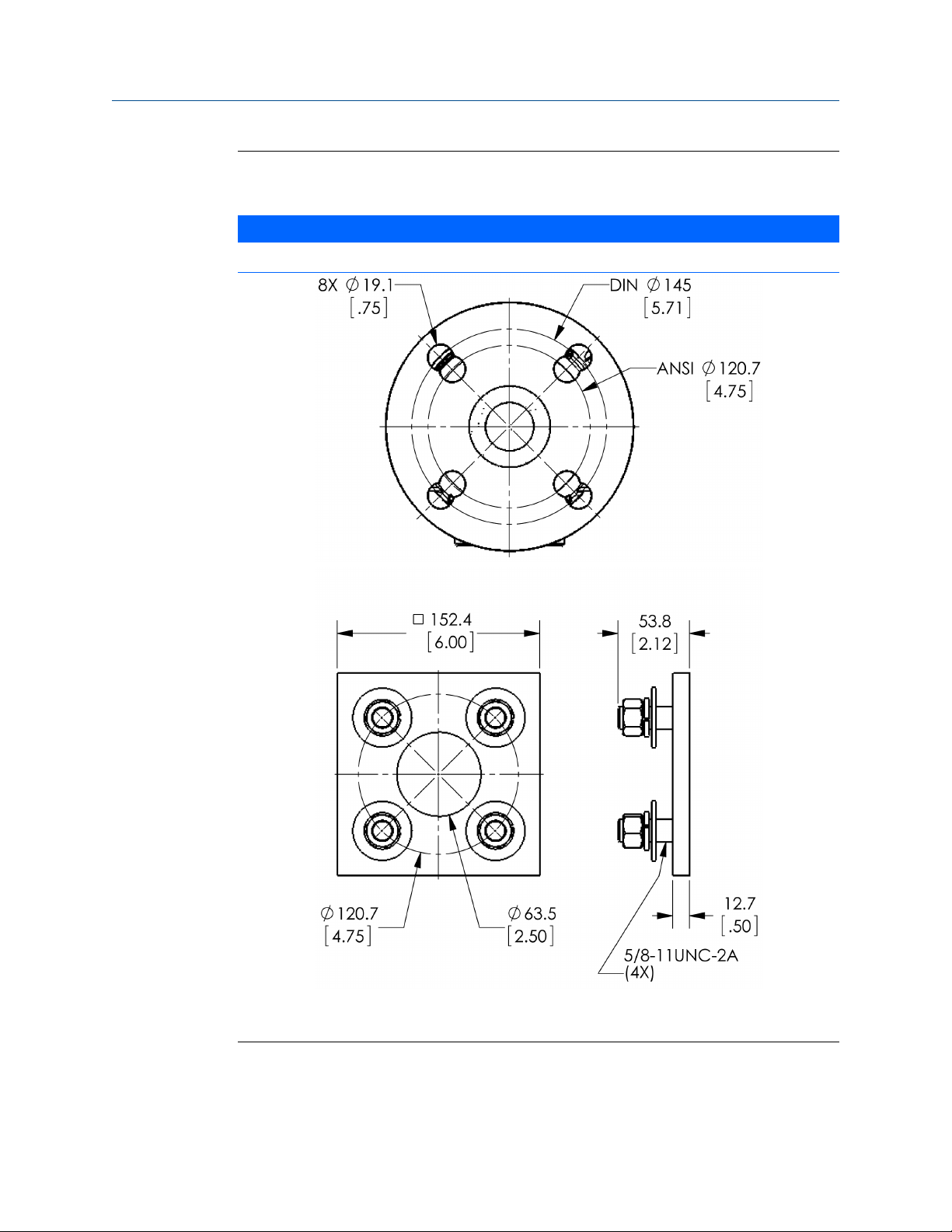
Rosemount CX1100 Probe InstallationFigure 1-2:
NOTICE
All dimensions are in millimeters with inches in parentheses.
Install
Square weld plate, ANSI pattern part 4512C34G01
Quick Start Guide 3
Page 8
Install
Mounting FlangeTable 1-2:
ANSI DIN
Flange dia 185 mm (7.28 in.)
Hold dia 19.1 mm (.75 in.)
4 holes eq sp on BC 120.7 mm (4.75 in.) 145 mm (5.71 in.)
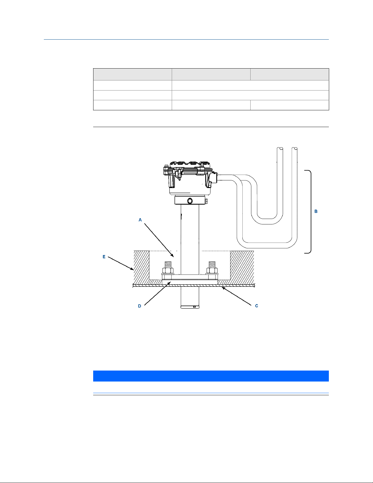
Drip loop and Insulation RemovalFigure 1-3:
A.
Note
Replace insulation after installing CX1100.
B. Drip loop
C. Stack duct or metal wall
D. Adapter plate
E. Insulation
NOTICE
Probe installation may be vertical or horizontal.
1.2
4 Rosemount™ CX1100
Mount remote display
Complete the following steps to install the Rosemount CX1100 Remote Transmitter.
Page 9

Install
The Rosemount CX1100 Remote Transmitter is available in a panel mounting or wall/pipe
mounting configuration. Refer to Figure 1-4 or Figure 1-5 for the panel, wall, or pipe
mounting details. You need a wrench and bolts to mount the transmitter.
Procedure
1. Ensure all components are available to install the Rosemount CX1100 Remote
Transmitter.
2. Select a mounting location near or removed from the Rosemount CX1100 Probe.
Consider the temperature limitations of the Rosemount CX1100 Remote
Transmitter. Refer to product specifications when selecting the mounting location.
3. Mount at a height convenient for viewing and operating the interface.
Emerson recommends approximately 5 ft. (1.5 m).
4. The keypad window on the Rosemount CX1100 Remote Transmitter may have an
exterior protective membrane. Remove the protective membrane prior to use of the
Rosemount CX1100 Remote transmitter.
Failure to remove the protective membrane may cause the display to appear
distorted. The membrane may become difficult or impossible to remove after
extended use at elevated temperatures.
Quick Start Guide 5
Page 10

Install
Wall/Surface and Pipe MountFigure 1-4:
6 Rosemount™ CX1100
Page 11

Install
Panel MountFigure 1-5:
Quick Start Guide 7
Page 12

Wire
2 Wire
All wiring must conform to local and national codes.
WARNING!
Before installing the equipment, read the Safety Instructions at the front of this manual. Failure
to follow safety instructions could result in serious injury or death.
NOTICE
To maintain proper earth grounding, ensure a positive connection exists between the probe
terminations housing and earth. The connecting wire must be 14 AWG minimum.
NOTICE
Line voltage, signal, and relay wiring must be rated for at least 221 °F (105 °C).
2.1
2.2
NOTICE
If metal conduit is used with the Rosemount™ CX1100 Remote Transmitter, reliably bond the
conduit to protective earth. The grounding plate inside the Rosemount CX1100 Remote
Transmitter is not bonded to PE and does not provide adequate grounding.
Installation specifications - interconnect cable
Customer supplied cable up to 200 ft. (60 m) long, rated for -40 to 194 °F (-40 to 90 °C)
and voltage 300 VACrms.
Heater power: 3 multi conductor 18ga shielded cable to connect the heater control signal
Probe sensing: 3 twisted pair conductors 22ga overall shielded cable to connect the TC,
O2, and CJC signals.
Cable may be purchased as two separate cables.
Connect the cables
Raw voltages from the oxygen sensor and heater thermocouple are transmitted from the
Rosemount CX1100 Probe to the Rosemount CX1100 Remote Transmitter. The remote
transmitter also controls power to the probe heater in order to maintain the correct sensor
temperature.
This arrangement calls for interconnect wiring consisting of nine conductors. Given the
recommended wire specifications, the maximum length for this cable is 200 ft (60 m)
(refer to Section 2.1).
8 Rosemount™ CX1100
Page 13

Wire
NOTICE
To maintain EMC/EMI noise protection, connect the customer supplied 9 conductor cable and
cable glands properly to ground.
Procedure
1. Run the signal and power cables between the probe and the installation site for the
optional Rosemount CX1100 Remote Transmitter.
2. Remove the covers from the probe and the remote transmitter (if applicable).
3. Feed all probe wiring through the conduit port of the probe.
4. Refer to Figure 2-2. Connect probe heater power leads to probe connector.
5. Connect O2 signal, thermocouple, and cold junction (CJC) wires from probe to the
Rosemount CX1100 Remote Transmitter.
6. At the Rosemount CX1100 Remote Transmitter, connect the cable leads to the
connectors on the sensor board as indicated in Figure 2-1.
Quick Start Guide 9
Page 14

Wire
Wiring DiagramFigure 2-1:
A. Heater power to probe
B. Alternate 4-20 mA out
C. Signal from probe
D. Power to remote transmitter
E. Alarm relay
10 Rosemount™ CX1100
Page 15

F. 4-20 mA out
G. Power supply
H. Combustion sensor
I. Shield ground
J. Heater power terminates to underside of the sensor board.
K. Probe sensing connect shield to GND
L. S1 Dip switch is for factory use only and should be in the Off position.
AC power wires from power supply board to the underside of the sensor board are provided with
the sensor board.
Wire
Quick Start Guide 11
Page 16

Wire
Closeup Wiring DiagramFigure 2-2:
A. M4 X 0.7 X 8 pan head screw machine screw (internal ground)
12 Rosemount™ CX1100
Page 17

3 Startup
1. Apply AC line power to the Rosemount™ CX1100 Remote Transmitter.
The probe takes approximately 45 minutes to warm up to the 1357 °F (736 °C)
setpoint. The 4-20 mA signal remains at a default value of 3.5 mA, and the O
reading remains at 0% through the warmup period.
2. After warmup, the probe begins reading oxygen, and the 4-20 mA output is based
on the default range of 0-10% O2.
If there is an error condition at startup, an alarm message is displayed on the
Rosemount CX1100 Remote Transmitter.
Startup
2
Quick Start Guide 13
Page 18

Calibration
4 Calibration
The Rosemount™ CX1100 In Situ Oxygen Transmitter can be calibrated in the installed
position without removing the instrument from the process duct and also while the
combustion process is online.Gas is applied to the sensor through the calibration gas
fitting. New Rosemount CX1100 In Situ Oxygen Transmitter systems are factory calibrated
and are generally acceptable for initial startup and operation. High accuracy can be gained
by calibrating a system during normal operating conditions. Emerson ™recommends
calibrating on a semi-annual to annual basis for most applications; however actual
calibration frequency may vary per process unit.
Calibrations are conducted using a two point calibration. Factory calibration uses 0.4% O
and 8.0% O2 gases with a balance of nitrogen and is therefore recommended. Calibration
gases with other oxygen concentrations are acceptable. If using different calibration gas
values, additional configuration through the Rosemount CX1100 Remote Transmitter is
required. Emerson does not recommend pure nitrogen as a calibration gas. Use a twostage pressure regulator to establish a pressure of 20 psi from the bottles and set the
flowmeter to 5 scfh (2.5 L/min) flow rate.
4.1 Procedure
The calibration of the Rosemount CX1100 Probe is initiated from the Rosemount CX1100
Remote Transmitter. The Rosemount CX1100 Remote Transmitter display prompts you
with the calibration instructions.
1. Press the x1 or x2 menu button on the Rosemount CX1100 Remote Transmitter
display to enter the probe.
2. Navigate, using Up and Down buttons to Setup; press Enter.
3. Navigate to Cal Gas values; press Enter.
4. Navigate to Cal Gas 1 and press Enter twice to highlight the value setting.
5. Use the Up and Down buttons to set Cal Gas 1 value and Left and Right buttons
to move to decimals setting.
6. After setting the correct value, press Enter and press Left to go to the Calibration
Setup for Cal Gas 2, Gas time, and Purge time settings.
2
7. After setting the values (0.4% O2, 8.0% O2, and 300s are the defaults), press Left to
go up to the Calibration submenu.
8. Navigate using the Up and Down buttons to Calibration and press Enter to start.
9. Follow the instructions on the display, manually applying calibration gases (0.4% and
8.0% O2 at 5 SCFH are recommended) to the calibration port.
10. After the calibration is finished, press Left and use the Up and Down buttons the
check the current and previous 10 calibrations log.
14 Rosemount™ CX1100
Page 19

Calibration
After completing the procedure, the Rosemount CX1100 software calculates new
calibration values and determines whether they meet an acceptance criteria. If successful,
the new calibration values automatically replace the previous values. In the event the
calibration values do not meet the accepted performance criteria, the existing calibration
values remain in effect, and Emerson recommends replacing the Rosemount CX1100
Probe.
CAUTION!
EQUIPMENT DAMAGE
Make sure that the calibration gas cap is replaced tightly after calibration is complete. Many
combustion processes operate at a slight negative pressure (draft pressure) and can draw
ambient air down the cal gas lines and into the sensing cell, causing a false elevated oxygen
reading. The same phenomenon is possible if the calibration gas hoses become degraded or
loose.
Quick Start Guide 15
Page 20

Product certifications
Appendix A
Product certifications
A.1 European Directive information
A copy of the EC Declaration of Conformity can be found at the end of the Quick Start
Guide. The most recent revision of the EC Declaration of Conformity can be found at
Emerson.com/Rosemount.
A.2 Ordinary location certification
As standard, the transmitter has been examined and tested to determine that the design
meets the basic electrical, mechanical, and fire protection requirements by a nationally
recognized test laboratory (NRTL) as accredited by the Federal Occupational Safety and
Health Administration (OSHA).
A.3 Installing equipment in North America
The US National Electrical Code (NEC) and the Canadian Electrical Code (CEC) permit the
use of Division marked equipment in Zones and Zone marked equipment in Divisions. The
marking must be suitable for the area classification, gas, and temperature class. This
information is clearly defined in the respective codes.
A.4
A.4.1 North America
Rosemount CX1100 In-Situ Oxygen Transmitter
CSA
Certificate: 70172073
Standards: CAN/CSA C22.2 No. 61010-1-12, CAN/CSA C22.2 No. 61010-2-010:15, UL
61010-1 (3rd Edition), UL 61010-2-10 (3rd Edition), UL 50E (2012), C22.2 No. 94.2-07, IEC
60529:2013 (Edition 2.2)
Markings: Type 4X, IP66
16 Rosemount™ CX1100
Page 21

Product certifications
Condition of acceptability:
1. The measuring of net O2 range is limited 0-23%.
2. The equipment shall be installed in accordance with manufacturer's specification by
qualified personnel.
3. This equipment is for permanently connection to power source with approved
power cord at end installation in accordance with local codes.
4. The Probe unit of the equipment shall be connected to PE separately at end
installation.
5. End installation to provide the means of disconnection from power sources.
6. End installation to comply with the requirement of IP66 and 4X.
Quick Start Guide 17
Page 22

EU Declaration of Conformity
No: RAD1116 Rev. A
We,
Rosemount Inc.
8200 Market Boulevard
Chanhassen, MN 55317-9685
USA
declare under our sole responsibility that the product,
Rosemount™ Oxygen Analyzer, Model CX1100
manufactured by,
Rosemount Inc.
8200 Market Boulevard
Chanhassen, MN 55317-9685
USA
to which this declaration relates, is in conformity with the provisions of the European Union
Directives, including the latest amendments, as shown here. Assumption of conformity is based
on the application of the harmonized standards and, when applicable or required, a European
Union notified body certification.
EMC Directive (2014/30/EU)
Harmonized Standards: EN 61326-1:2013
Low Voltage Directive (2014/35/EU)
Harmonized Standards: EN 61010-1:2010
PED Directive (2014/68/EU)
Sound Engineering Practice
(signature)
Chris LaPoint
(name)
Page 1 of 1
Vice President of Global Quality
(function)
7-Mar-18; Shakopee, MN USA
(date of issue & place)
Page 23

Product certifications
18 Rosemount™ CX1100
Page 24

00825-0100-4110
Rev AA
2018
GLOBAL HEADQUARTERS
Emerson Automation Solutions
6021 Innovation Blvd
Shakopee, MN 55379, USA
+1 800 999 9307 or +1 952 906 8888
+1 952 949 7001
gas.csc@emerson.com
EUROPE
Emerson Automation Solutions
Neuhofstrasse 19a P.O. Box 1046
CH-6340 Baar
Switzerland
+ 41 (0) 41 768 6111
+ 41 (0) 41 768 6300
gas.csc@emerson.com
Linkedin.com/company/Emerson-Automation-Solutions
twitter.com/rosemount_news
Facebook.com/Rosemount
youtube.com/RosemountMeasurement
google.com/+RosemountMeasurement
AnalyticExpert.com
NORTH AMERICA
Rosemount
8200 Market Boulevard
Chanhassen, MN 55317
+1 800 999 9307
+1 952 949 7001
gas.csc@emerson.com
MIDDLE EAST AND AFRICA
Emerson Automation Solutions
Emerson FZE
Jebel Ali Free Zone
Dubai, United Arab Emirates, P.O. Box 17033
+971 4 811 8100
+971 4 886 5465
gas.csc@emerson.com
©
2018 Emerson. All rights reserved.
The Emerson logo is a trademark and service mark of Emerson Electric Co. Rosemount is a
mark of one of the Emerson family of companies. All other marks are the property of their
respective owners.
ASIA-PACIFIC
Emerson Automation Solutions
1 Pandan Crescent
Singapore 128461
Singapore
+65 777 8211
+65 777 0947
gas.csc@emerson.com
 Loading...