

Page 1
2.0 INSTALLATION
2.1 UNPACKING AND INSPECTION
Inspect the carton for damage. If damage is found, contact the carrier immediately.
2.2 SENSOR PREPARATION
Sensor Preparation Guidelines: Carefully remove the plastic cap covering
the sensing end of the sensor. Avoid causing a vacuum by gently and slowly
twisting the sensor and cap until it is removed. Sensor is shipped dry, so electrolyte must be added prior to installation.
Remove membrane cartridge. Add 2 ml of electrolyte to the membrane cartridge. Screw membrane cartridge back onto sensor body. Refer to Section
6.3 for additional details.
Connection of the Sensor to the Analyzer/ Transmitter:
1. Wire the sensor to the analyzer/transmitter. See the wiring tables in
Section 3.0.
2. Apply power to the analyzer/transmitter. After 24 hours, the sensor should
be ready for calibration. The polarization time is necessary to get stable
signals from the sensor. If the sensor is disconnected from the
analyzer/transmitter for a short time, allow the sensor to stabilize for at
least three times longer than the time is was disconnected. Time needed
for stabilization should not exceed 24 hours.
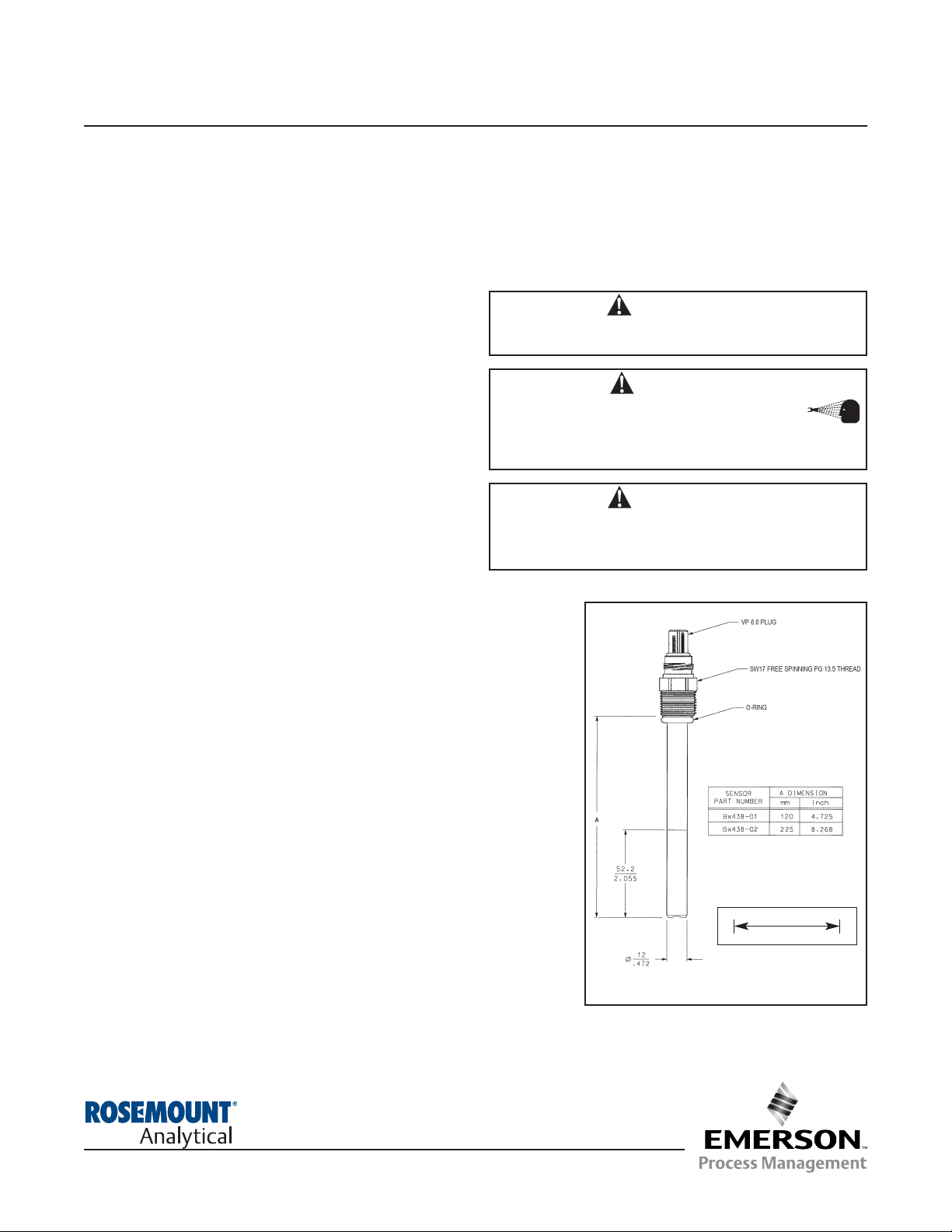
Mounting Guidelines: Mount the sensor using the PG 13.5 process thread.
NOTE
Do not install the sensor upside down.
Model Bx438
Dissolved Oxygen Sensor
Instruction Sheet
PN 51A-Bx438/rev.D
July 2005
MILLIMETER
INCH
WARNING
The electrolyte is acidic. Protect your hands with gloves and
use safety goggles. Avoid contact of the electrolyte with the
skin, eyes, and mucous membranes.
WARNING
Do not exceed temperature and pressure limitations of
100°C (212°F) and 174 psig (1200 kpa abs, 12 bar).
WARNING
Before removing the sensor, be absolutely
certain that the process pressure is reduced to
0 psig and the process temperature is lowered
to a safe level!
1.0 SPECIFICATIONS
Temperature Range: -10 to 100°C (14 to 212°F)
Maximum Pressure: 174 psig (1200 kpa abs, 12 bar)
Measurement Range: 10 ppb to 20 ppm or 0.1% to 200%
saturation, depending on instrument
Wetted Materials: Stainless Steel, Gold, Silicone, FDA-
approved EPDM
Process Connections: PG 13.5 thread
Cable Connector: Variopol
Cable Compatibility: VP 6.0
Compatible Analyzers: Rosemount Analytical Models 54eA,
5081-A, and Xmt-A
Compatible Mounting Accessory: Insertion or Retractable
Mounting Assembly, TriClamp Assembly
MODEL Bx438
For additional information, please refer to the Instruction Manuals CD shipped with this
product, or visit our website at www.emersonprocess.com/raihome/liquid/.
Page 2
2
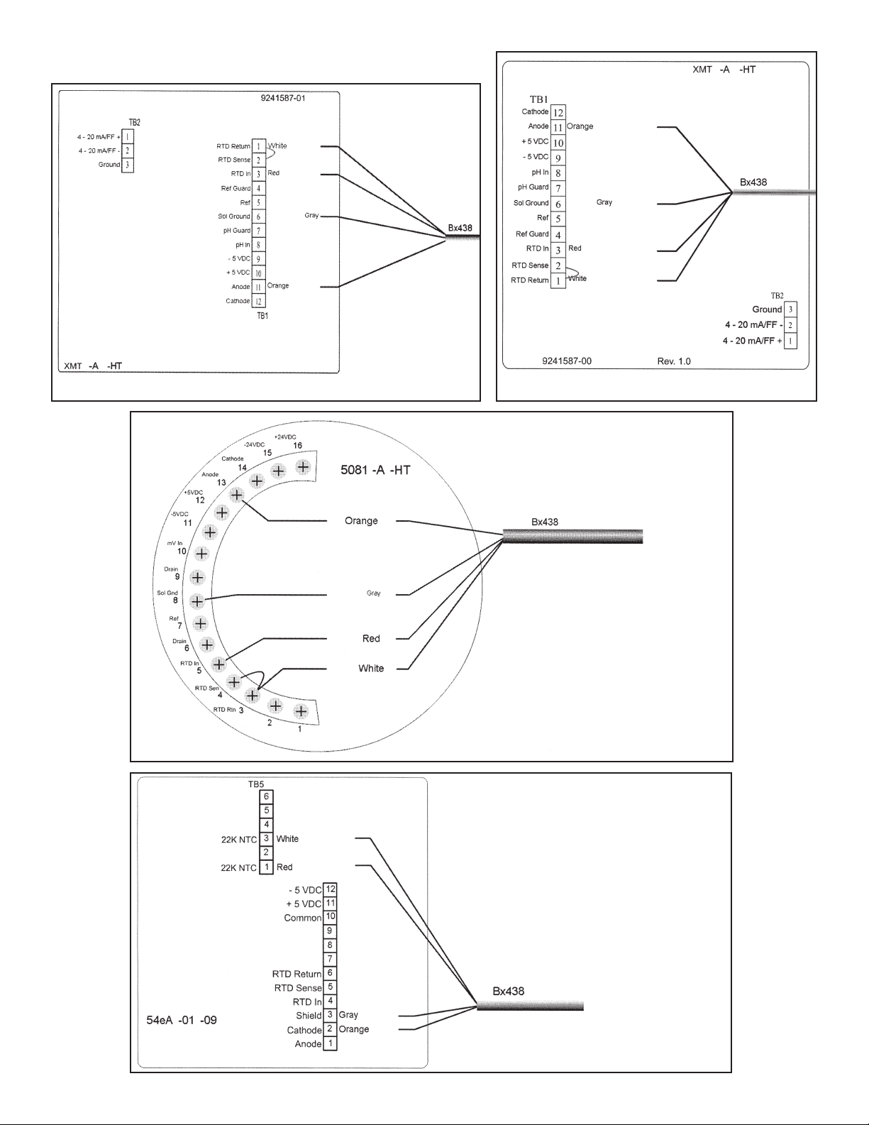
3.0 WIRING
Model 54eA Wiring
Model Bx438 uses a 22k NTC thermistor. The
thermistor is wired to terminals 1 and 3 of TB5.
Model Xmt-A-HT-10 WiringModel Xmt-A-HT-11 Wiring
Model 5081-A Wiring
Page 3

4.0 STERILIZATION
Before autoclaving the sensor, cover the connector end of
the sensor with a tight protective cap (PN 9160490). If the
connector end gets wet despite the protective cap, dry the
connector with pressurized air or a hair dryer. Drying prevents corrosion and damage to insulation.
No protection is necessary when doing in-situ sterilization.
5.0 INSTRUMENT SET-UP
The analyzer must be set up for the proper service.
5.1 MODEL 54eA
Program the 54eA as follows:
Measure: Oxygen
Sensor: SSDO other
Measure Units: % sat, ppb or ppm (depending on
service)
5.2 MODEL Xmt-A
Program the Xmt-A as follows:
Measure: Oxygen
Manufacturer: Rosemount
Application: Biopharm
Units: % sat, ppb or ppm (depending on service)
Refer to Model Xmt-A manual (PN 51-Xmt-A-HT) for additional set-up instructions.
5.3 MODEL 5081-A
Program the Xmt-A as follows:
Type: O
2
Units: ppm, ppb, or % (depending on service)
Sensor: Sd01
Refer to Model 5081-A manual (PN 51-5081A-HT) for additional set-up instructions.
6.0 CALIBRATION AND MAINTENANCE
Dismounting the sensor: Unscrew the free rotating PG
13.5 threaded connector and pull the sensor out of the
process or mounting assembly.
6.1 CALIBRATION
1. Refer to the analyzer instruction manual for details.
2. Be sure the sensor has been operating for at least 24
hours before zeroing and calibrating.
3. Perform a zero check of the sensor by placing it in
nitrogen gas or in water containing about 5% sodium
sulfite. If using nitrogen gas, be sure the membrane is
dry. Make sure the current output drops below 1 nA. If
the sensor does not reach 1 nA, then either the zero
solution needs to be replaced or the sensor membrane
needs to be replaced.
4. If sodium sulfite was used to zero the sensor, rinse the
sensor with water and gently dry the membrane. Place
the sensor in water-saturated air. Once the reading is
stable, complete the full-scale calibration. Consult the
analyzer instruction manual for details.
5. Calibration can also be done using air-saturated water
or air-saturated medium. Although the sensor has an
extremely low oxygen consumption rate, the liquid
should be gently stirred during calibration.
NOTE
A warning message “Sensor output very low/ high”
may appear on the 54eA. Press cont (F3 key).
Verify that the sensor output in air meets factory
specifications (180 nA - 400 nA).
6.2 SENSOR MAINTENANCE
Periodically check sensor response in air and nitrogen.
1. Place the sensor in air. Allow the reading to become
stable and note the value. Also note the sensor current,
which should be between 180 and 400 nA.
2. Place the sensor in nitrogen. A small plastic bag with a
stream of nitrogen gas discharging into the bottom
works well.
3. After 90 seconds, the sensor current should be less
than 2% of the value in air.
For troubleshooting information, see Section 7.0.
6.3 REPLACING THE ELECTROLYTE AND THE MEM-
BRANE CARTRIDGE:
Replace the membrane cartridge (membrane kit PN
24107-00) as follows:
1. Hold the sensor vertically with the membrane pointing
down. Carefully unscrew the membrane cartridge.
2. Carefully clean the tip of the glass body with a soft tissue, or clean with the polishing tool in one direction
only.
WARNING
Do not polish the cathode!
NOTE
When replacing the membrane cartridge,
do not touch the anode wire.
3. Check the small o-ring above the glass body. If it is
damaged, replace it.
4. Use the plastic pipette in the membrane kit to add
1.5 ml of electrolyte solution to the new membrane
cartridge.
5. Carefully screw the cartridge onto the sensor shaft. If
too much electrolyte solution was used, the excess
must be pushed out. Wash off the excess electrolyte
with water.
3
Page 4

7.0 TROUBLESHOOTING
Below is a list of possible problems and solutions for Model Bx438 dissolved oxygen sensor.
CURRENT IN AIR TOO HIGH SLUGGISH RESPONSE CURRENT IN AIR TOO LOW
(>500 nA at 25°C) (<80 nA at 25°C)
Problem Solution Problem Solution Problem Solution
Very thin or defective Replace with new Contaminated, fouled, Clean membrane or Contaminated, fouled, Clean membrane or
membrane membrane cartridge or dirty membrane replace with new or dirty membrane replace with new
membrane cartridge membrane cartridge
Defective glass body Return to Rosemount Loose membrane Replace with new Dried out electrolyte Loosen membrane
or connector Analytical, Liquid Div. membrane cartridge film cartridge and tighten
Poisoned anode Return to Rosemount Dried out electrolyte Loosen membrane Cathode contaminated Return to Rosemount
Analytical, Liquid Div. film cartridge and tighten by silver Analytical, Liquid Div
— — Cathode contaminated Return to Rosemount Exhausted electrolyte Fill with new
by silver Analytical, Liquid Div electrolyte
— — — — Defective glass body Return to Rosemount
or connector Analytical, Liquid Div
Membrane kit consists of three replacement membranes and spare o-rings. Reference part number 24107-00.
Electrolyte must be purchased separately. Reference part number 24108-00.
Credit Cards for U.S. Purchases Only.
The right people,
the right answers,
right now.
ON-LINE ORDERING NOW AVAILABLE ON OUR WEB SITE
http://www.raihome.com
Specifications subject to change without notice.
Emerson Process Management
Liquid Division
2400 Barranca Parkway
Irvine, CA 92606 USA
Tel: (949) 757-8500
Fax: (949) 474-7250
http://www.raihome.com
© Rosemount Analytical Inc. 2005
 Loading...