

Page 1

Instruction Manual
IM-106-5081, Rev 2.0
October 2008
Model 5081FG
Two-Wire In Situ
Oxygen Analyzer
(550° to 1600°C)
http://www.raihome.com
Page 2

Page 3

HIGHLIGHTS OF CHANGES
Effective October 31, 2008 Rev. 2.0
Page Summary
General Reformatted entire manual in accordance with Emerson Process Management style
guide. Revised all illustration formats.
Cover Updated manual revision level and release date.
1-5 Revised Figure 1-2.
1-7 Revised Specifications.
1-9 Revised Table 1-1, Product Matrix.
2-11 Corrected reference to installation drawings in the warning regarding intrinsically safe
applications.
2-14 Revised Reference Air Package illustrations.
3-3 Revised Figure 3-3.
3-5 Revised Figure 3-5 to reflect update to Diagnostics Menu.
3-7 Added Operator Adjustable Parameters discussion and Table 3-1.
3-18, 3-19 Added Current Slope and Current Constant diagnostic descriptions.
4-2, 4-3 Revised Figures 4-1 and 4-2.
4-5, 4-6, 4-7 Revised Figure 4-3, sheets 1, 2, and 3.
5-8 Added Calibration Passes discussion.
6-1 through 6-5 Revised all procedures to reflect changes to Figure 6-1.
6-2 Revised Figure 6-1 to reflect components configuration changes.
7-1 Revised Table 7-1, Replacement Parts list. Updated part numbers.
Appendix C Added new Appendix C containing installation drawings for intrinsically safe applications.
Page 4

Page 5

Instruction Manual
IM-106-5081, Rev 2.0
October 2008
Model 5081FG
Table of Contents
SECTION i
Introduction
SECTION 1
Description and
Specifications
SECTION 2
Installation
Preface. . . . . . . . . . . . . . . . . . . . . . . . . . . . . . . . . . . . . . . . . . . . . . . . . . iv
Definitions . . . . . . . . . . . . . . . . . . . . . . . . . . . . . . . . . . . . . . . . . . . . . . . iv
Symbols . . . . . . . . . . . . . . . . . . . . . . . . . . . . . . . . . . . . . . . . . . . . . . . . . iv
Technical Support Hotline: . . . . . . . . . . . . . . . . . . . . . . . . . . . . . . . . iv
Component Checklist . . . . . . . . . . . . . . . . . . . . . . . . . . . . . . . . . . . . . . 1-1
System Overview . . . . . . . . . . . . . . . . . . . . . . . . . . . . . . . . . . . . . . . . . 1-3
Scope . . . . . . . . . . . . . . . . . . . . . . . . . . . . . . . . . . . . . . . . . . . . . . .1-3
System Description . . . . . . . . . . . . . . . . . . . . . . . . . . . . . . . . . . . . .1-3
System Configuration . . . . . . . . . . . . . . . . . . . . . . . . . . . . . . . . . . . 1-4
System Features. . . . . . . . . . . . . . . . . . . . . . . . . . . . . . . . . . . . . . . 1-4
Handling the Analyzer . . . . . . . . . . . . . . . . . . . . . . . . . . . . . . . . . . . 1-6
System Considerations . . . . . . . . . . . . . . . . . . . . . . . . . . . . . . . . . .1-6
Specifications . . . . . . . . . . . . . . . . . . . . . . . . . . . . . . . . . . . . . . . . . . . . 1-7
Pre-Installation . . . . . . . . . . . . . . . . . . . . . . . . . . . . . . . . . . . . . . . . . . .2-2
Inspect . . . . . . . . . . . . . . . . . . . . . . . . . . . . . . . . . . . . . . . . . . . . . . 2-2
Packing List. . . . . . . . . . . . . . . . . . . . . . . . . . . . . . . . . . . . . . . . . . . 2-2
Mechanical Installation . . . . . . . . . . . . . . . . . . . . . . . . . . . . . . . . . . . . 2-2
Locating Oxygen Probe . . . . . . . . . . . . . . . . . . . . . . . . . . . . . . . . . 2-2
Installing Oxygen Probe . . . . . . . . . . . . . . . . . . . . . . . . . . . . . . . . .2-4
Locating Model 5081 Transmitter . . . . . . . . . . . . . . . . . . . . . . . . . . 2-7
Installing Model 5081 Transmitter. . . . . . . . . . . . . . . . . . . . . . . . . . 2-8
Electrical Installation . . . . . . . . . . . . . . . . . . . . . . . . . . . . . . . . . . . . . 2-11
General . . . . . . . . . . . . . . . . . . . . . . . . . . . . . . . . . . . . . . . . . . . . . 2-11
Oxygen Probe Signal Connections . . . . . . . . . . . . . . . . . . . . . . . .2-12
Model 5081 Transmitter 4-20 mA and Signal Connections . . . . . 2-13
Pneumatic Installation . . . . . . . . . . . . . . . . . . . . . . . . . . . . . . . . . . . .2-14
General . . . . . . . . . . . . . . . . . . . . . . . . . . . . . . . . . . . . . . . . . . . . . 2-14
Reference Air Package . . . . . . . . . . . . . . . . . . . . . . . . . . . . . . . . . 2-14
Instrument Air (Reference Air) . . . . . . . . . . . . . . . . . . . . . . . . . . . 2-14
Calibration Gas . . . . . . . . . . . . . . . . . . . . . . . . . . . . . . . . . . . . . . . 2-15
SECTION 3
Startup and
Operation
General . . . . . . . . . . . . . . . . . . . . . . . . . . . . . . . . . . . . . . . . . . . . . . . . 3-1
Power Up . . . . . . . . . . . . . . . . . . . . . . . . . . . . . . . . . . . . . . . . . . . . . . . 3-1
Establishing Proper Calibration Gas Flow Rate . . . . . . . . . . . . . . . . .3-3
Operation . . . . . . . . . . . . . . . . . . . . . . . . . . . . . . . . . . . . . . . . . . . . . . . 3-4
Overview . . . . . . . . . . . . . . . . . . . . . . . . . . . . . . . . . . . . . . . . . . . . . 3-4
Display . . . . . . . . . . . . . . . . . . . . . . . . . . . . . . . . . . . . . . . . . . . . . . 3-4
Menu Tree. . . . . . . . . . . . . . . . . . . . . . . . . . . . . . . . . . . . . . . . . . . .3-4
Navigation . . . . . . . . . . . . . . . . . . . . . . . . . . . . . . . . . . . . . . . . . . . . 3-6
Program Menu . . . . . . . . . . . . . . . . . . . . . . . . . . . . . . . . . . . . . . . . . . . 3-7
Operator Adjustable Parameters . . . . . . . . . . . . . . . . . . . . . . . . . .3-7
Code . . . . . . . . . . . . . . . . . . . . . . . . . . . . . . . . . . . . . . . . . . . . . . . . 3-8
Display Code. . . . . . . . . . . . . . . . . . . . . . . . . . . . . . . . . . . . . . . . . .3-9
Fault Val . . . . . . . . . . . . . . . . . . . . . . . . . . . . . . . . . . . . . . . . . . . . .3-9
Upper Range Val . . . . . . . . . . . . . . . . . . . . . . . . . . . . . . . . . . . . .3-10
TOC-1
Page 6

Model 5081FG
Instruction Manual
IM-106-5081, Rev 2.0
October 2008
Cell T Hi . . . . . . . . . . . . . . . . . . . . . . . . . . . . . . . . . . . . . . . . . . . . 3-10
Reset Max Cell T . . . . . . . . . . . . . . . . . . . . . . . . . . . . . . . . . . . . . 3-11
Set O2 Filter Time . . . . . . . . . . . . . . . . . . . . . . . . . . . . . . . . . . . . 3-11
Trim 4mA? . . . . . . . . . . . . . . . . . . . . . . . . . . . . . . . . . . . . . . . . . . 3-12
Trim 20mA? . . . . . . . . . . . . . . . . . . . . . . . . . . . . . . . . . . . . . . . . . 3-13
Set Hi Bottle O2 . . . . . . . . . . . . . . . . . . . . . . . . . . . . . . . . . . . . . . 3-14
Set Lo Bottle O2 . . . . . . . . . . . . . . . . . . . . . . . . . . . . . . . . . . . . . . 3-14
Set O2 Tracking . . . . . . . . . . . . . . . . . . . . . . . . . . . . . . . . . . . . . . 3-15
Set Code. . . . . . . . . . . . . . . . . . . . . . . . . . . . . . . . . . . . . . . . . . . . 3-15
Diagnostics Menu . . . . . . . . . . . . . . . . . . . . . . . . . . . . . . . . . . . . . . . 3-16
Show Fault . . . . . . . . . . . . . . . . . . . . . . . . . . . . . . . . . . . . . . . . . . 3-16
T/C mV . . . . . . . . . . . . . . . . . . . . . . . . . . . . . . . . . . . . . . . . . . . . . 3-17
O2 CELL mV . . . . . . . . . . . . . . . . . . . . . . . . . . . . . . . . . . . . . . . . 3-17
Cell Impedance. . . . . . . . . . . . . . . . . . . . . . . . . . . . . . . . . . . . . . . 3-18
Current Slope . . . . . . . . . . . . . . . . . . . . . . . . . . . . . . . . . . . . . . . . 3-18
Current Constant . . . . . . . . . . . . . . . . . . . . . . . . . . . . . . . . . . . . . 3-19
Previous Slope . . . . . . . . . . . . . . . . . . . . . . . . . . . . . . . . . . . . . . . 3-19
Previous Constant . . . . . . . . . . . . . . . . . . . . . . . . . . . . . . . . . . . . 3-20
Max Cell T . . . . . . . . . . . . . . . . . . . . . . . . . . . . . . . . . . . . . . . . . . 3-20
SW Ver (SOFt) . . . . . . . . . . . . . . . . . . . . . . . . . . . . . . . . . . . . . . . 3-21
Unit Ser # (SEr) . . . . . . . . . . . . . . . . . . . . . . . . . . . . . . . . . . . . . . 3-21
SW Build Number (bLdn) . . . . . . . . . . . . . . . . . . . . . . . . . . . . . . . 3-21
SW Build Date (bd). . . . . . . . . . . . . . . . . . . . . . . . . . . . . . . . . . . . 3-21
Cal Check Menu . . . . . . . . . . . . . . . . . . . . . . . . . . . . . . . . . . . . . . . . 3-21
In Manual? . . . . . . . . . . . . . . . . . . . . . . . . . . . . . . . . . . . . . . . . . . 3-21
Accept High O2 . . . . . . . . . . . . . . . . . . . . . . . . . . . . . . . . . . . . . . 3-22
Accept Low O2 . . . . . . . . . . . . . . . . . . . . . . . . . . . . . . . . . . . . . . . 3-22
Slope . . . . . . . . . . . . . . . . . . . . . . . . . . . . . . . . . . . . . . . . . . . . . . 3-23
Constant . . . . . . . . . . . . . . . . . . . . . . . . . . . . . . . . . . . . . . . . . . . . 3-23
SECTION 4
HART/AMS
SECTION 5
Troubleshooting
SECTION 6
Maintenance and Service
Overview . . . . . . . . . . . . . . . . . . . . . . . . . . . . . . . . . . . . . . . . . . . . . . . 4-1
Field Communicator Signal Line Connections. . . . . . . . . . . . . . . . . . . 4-2
Field Communicator PC Connections . . . . . . . . . . . . . . . . . . . . . . . . . 4-4
Off-Line and On-Line Operations. . . . . . . . . . . . . . . . . . . . . . . . . . . . . 4-4
HART/AMS Menu Tree . . . . . . . . . . . . . . . . . . . . . . . . . . . . . . . . . . . . 4-4
Field Communicator Start Cal Check Method . . . . . . . . . . . . . . . . . . . 4-8
General . . . . . . . . . . . . . . . . . . . . . . . . . . . . . . . . . . . . . . . . . . . . . . . . 5-1
Probe Life . . . . . . . . . . . . . . . . . . . . . . . . . . . . . . . . . . . . . . . . . . . . . . 5-1
Fault Indications. . . . . . . . . . . . . . . . . . . . . . . . . . . . . . . . . . . . . . . . . . 5-3
Identifying And Correcting Fault Indications . . . . . . . . . . . . . . . . . . . 5-4
Calibration Passes, But Still Reads Incorrectly . . . . . . . . . . . . . . . . . . 5-8
Probe Passes
Calibration, O2 Still
Reads High. . . . . . . . . . . . . . . . . . . . . . . . . . . . . . . . . . . . . . . . . . . 5-8
Overview . . . . . . . . . . . . . . . . . . . . . . . . . . . . . . . . . . . . . . . . . . . . . . . 6-1
Electronics
Replacement . . . . . . . . . . . . . . . . . . . . . . . . . . . . . . . . . . . . . . . . . . . . 6-1
Display Board Replacement . . . . . . . . . . . . . . . . . . . . . . . . . . . . . . 6-1
Spare Board Stack Replacement . . . . . . . . . . . . . . . . . . . . . . . . . . 6-3
Oxygen Probe Replacement . . . . . . . . . . . . . . . . . . . . . . . . . . . . . . . . 6-3
TOC-2
Page 7

Instruction Manual
IM-106-5081, Rev 2.0
October 2008
SECTION 7
Replacement Parts
Model 5081FG
APPENDIX A
Safety Data
APPENDIX B
Return of Material
APPENDIX C
Schematics
Safety Instructions . . . . . . . . . . . . . . . . . . . . . . . . . . . . . . . . . . . . . . . A-2
Safety Data Sheet for Ceramic Fiber Products . . . . . . . . . . . . . . . . A-24
. . . . . . . . . . . . . . . . . . . . . . . . . . . . . . . . . . . . . . . . . . . . . . . . . . . . . A-30
Returning Material . . . . . . . . . . . . . . . . . . . . . . . . . . . . . . . . . . . . . . . B-1
Installation Schematics . . . . . . . . . . . . . . . . . . . . . . . . . . . . . . . . . . . C-1
TOC-3
Page 8

Model 5081FG
Instruction Manual
IM-106-5081, Rev 2.0
October 2008
TOC-4
Page 9
Instruction Manual
IM-106-5081, Rev. 2.0
October 2008
Model 5081FG
Oxygen Analyzers
READ THIS PAGE BEFORE PROCEEDING!
ESSENTIAL INSTRUCTIONS
Emerson Process Management designs, manufactures and tests its products
to meet many national and international standards. Because these
instruments are sophisticated technical products, you MUST properly
install, use, and maintain them to ensure they continue to operate within
their normal specifications. The following instructions MUST be adhered to
and integrated into your safety program when installing, using, and
maintaining Emerson’s Rosemount Analytical products. Failure to follow the
proper instructions may cause any one of the following situations to occur:
Loss of life; personal injury; property damage; damage to this instrument; and
warranty invalidation.
• Read all instructions
product.
• If you do not understand any of the instructions, contact your
Emerson Process Management representative for clarification.
• Follow all warnings, cautions, and instructions
supplied with the product.
• Inform and educate your personnel in the proper installation,
operation, and maintenance of the product.
• Install your equipment as specified in the Installation Instructions
of the appropriate Instruction Manual and per applicable local and
national codes. Connect all products to the proper electrical and
pressure sources.
• To ensure proper performance, use qualified personnel
operate, update, program, and maintain the product.
• When replacement parts are required, ensure that qualified people use
replacement parts specified by Emerson Process Management.
Unauthorized parts and procedures can affect the product's
performance, place the safe operation of your process at risk, and
VOID YOUR WARRANTY. Look-alike substitutions may result in fire,
electrical hazards, or improper operation.
• Ensure that all equipment doors are closed and protective covers
are in place, except when maintenance is being performed by
qualified persons, to prevent electrical shock and personal injury.
prior to installing, operating, and servicing the
marked on and
to install,
http://www.raihome.com
The information contained in this document is subject to change without
notice.
If a Model 275/375 Universal HART® Communicator is used with this unit, the software
within the Model 275/375 may require modification. If a software modification is required,
please contact your local Emerson Process Management Service Group or National
Response Center at 1-800-433-6076 or 1-888-433-6829.
Page 10

Model 5081FG
Instruction Manual
IM-106-5081, Rev. 2.0
October 2008
ii
Page 11

Instruction Manual
IM-106-5081, Rev. 2.0
October 2008
Section i Introduction
Preface . . . . . . . . . . . . . . . . . . . . . . . . . . . . . . . . . . . . . . . . . page i-iv
Definitions . . . . . . . . . . . . . . . . . . . . . . . . . . . . . . . . . . . . . . page i-iv
Symbols . . . . . . . . . . . . . . . . . . . . . . . . . . . . . . . . . . . . . . . . page i-iv
Model 5081FG
http://www.raihome.com
Page 12
Instruction Manual
IM-106-5081, Rev. 2.0
Model 5081FG
October 2008
PREFACE The purpose of this manual is to provide information concerning the
components, functions, installation and maintenance of the Model 5081FG
Two-Wire In Situ Oxygen Analyzer (550° to 1600°C).
Some sections may describe equipment not used in your configuration. The
user should become thoroughly familiar with the operation of this module
before operating it. Read this instruction manual completely.
DEFINITIONS The following definitions apply to WARNINGS, CAUTIONS, and NOTES
found throughout this publication.
Highlights an operation or maintenance procedure, practice, condition, statement, etc. If not
strictly observed, could result in injury, death, or long-term health hazards of personnel.
Highlights an operation or maintenance procedure, practice, condition, statement, etc. If not
strictly observed, could result in damage to or destruction of equipment, or loss of
effectiveness.
SYMBOLS
Technical Support Hotline:
NOTE
Highlights an essential operating procedure, condition, or statement.
:
EARTH (GROUND) TERMINAL
:
PROTECTIVE CONDUCT OR TERMINAL
:
RISK OF ELECTRICAL SHOCK
:
WARNING: REFER TO INSTRUCTION MANUAL
NOTE TO USERS
The number in the lower right corner of each illustration in this publication is a
manual illustration number. It is not a part number, and is not related to the
illustration in any technical manner.
For assistance with technical problems, please call the Customer Support
Center (CSC). The CSC is staffed 24 hours a day, 7 days a week.
Phone: 1-800-433-6076 1-440-914-1261
In addition to the CSC, you may also contact Field Watch. Field Watch
coordinates Emerson Process Management’s field service throughout the
U.S. and abroad.
Phone: 1-800-654-RSMT (1-800-654-7768)
Emerson Process Management may also be reached via the Internet through:
e-mail: GAS.CSC@emerson.com
World Wide Web: www.raihome.com
iv
Page 13

Instruction Manual
IM-106-5081, Rev. 2.0
October 2008
Model 5081FG
Section 1 Description and Specifications
Component Checklist . . . . . . . . . . . . . . . . . . . . . . . . . . . . . page 1-1
System Overview . . . . . . . . . . . . . . . . . . . . . . . . . . . . . . . . page 1-3
Specifications . . . . . . . . . . . . . . . . . . . . . . . . . . . . . . . . . . . page 1-7
COMPONENT CHECKLIST
A typical Rosemount Analytical Two-Wire In Situ Oxygen Analyzer should
contain the items shown in Figure 1-1. Record the part number, serial number,
and order number for each component of your system in the table located on
the first page of this manual.
Also, use the product matrix in Table 1-1 at the end of this section to compare
your order number against your unit. The first part of the matrix defines the
model. The last part defines the various options and features of the Model
5081FG Analyzer. Ensure the features and options specified by your order
number are on or included with the unit.
http://www.raihome.com
Page 14
Model 5081FG
Figure 1-1. Typical System Package
Instruction Manual
IM-106-5081, Rev. 2.0
October 2008
1. Instruction Manual
2. Model 5081 Transmitter
3. Oxygen Probe
4. Adapter Plate with Mounting Hardware and Gasket (Optional)
5. Infrared Remote Control (IRC)
6. Reference Air Set (Optional)
7. Field Communicator Package (Optional)
8. Pipe Mounting Kit (Optional)
1-2
Page 15

Instruction Manual
IM-106-5081, Rev. 2.0
October 2008
Model 5081FG
SYSTEM OVERVIEW
Scope This Instruction Bulletin is designed to supply details needed to install, start
up, operate, and maintain the Rosemount Analytical Two-Wire In Situ Oxygen
Analyzer. The analyzer consists of an oxygen probe and Model 5081
transmitter. The signal conditioning electronics of the Model 5081 transmitter
outputs a 4-20 mA signal representing an O
control (IRC) allows access to setup, calibration, and diagnostics. This same
information, plus additional details, can be accessed with the HART field
communicator or Asset Management Solutions (AMS) software.
value. An infrared remote
2
System Description The Rosemount Analytical Two-Wire In Situ Oxygen Analyzer is designed to
measure the net concentration of oxygen in an industrial process; i.e., the
oxygen remaining after all fuels have been oxidized. The oxygen probe is
permanently positioned within an exhaust duct or stack and performs its task
without the use of a sampling system. The Model 5081 transmitter is mounted
remotely and conditions the oxygen probe outputs.
The equipment measures oxygen percentage by reading the voltage
developed across a heated electrochemical cell, which consists of a small
yttria stabilized, zirconia disc. Both sides of the disc are coated with porous
metal electrodes. When operated at the proper temperature, the millivolt
output voltage of the cell is given by the following Nernst equation:
EMF = KT log10(P1/P2) + C
Where:
1. P2 is the partial pressure of the oxygen in the measured gas on one
side of the cell.
2. P1 is the partial pressure of the oxygen in the reference air on the
opposite side of the cell.
3. T is the absolute temperature.
4. C is the cell constant.
5. K is an arithmetic constant.
NOTE
For best results, use clean, dry, instrument air (20.95% oxygen) as the
reference air.
NOTE
The probe uses a Type B thermocouple to measure the cell temperature.
When the cell is at operating temperature and there are unequal oxygen
concentrations across the cell, oxygen ions will travel from the high oxygen
partial pressure side to the low oxygen partial pressure side of the cell. The
resulting logarithmic output voltage is approximately 50 mV per decade.
The output is proportional to the inverse logarithm of the oxygen
concentration. Therefore, the output signal increases as the oxygen
concentration of the sample gas decreases. This characteristic enables the
Rosemount Analytical Two-Wire In Situ Oxygen Analyzer to provide
exceptional sensitivity at low oxygen concentrations.
1-3
Page 16

Instruction Manual
IM-106-5081, Rev. 2.0
Model 5081FG
The oxygen analyzer measures net oxygen concentration in the presence of
all the products of combustion, including water vapor. Therefore, it may be
considered an analysis on a "wet" basis. In comparison with older methods,
such as the portable apparatus, which provides an analysis on a "dry" gas
basis, the "wet" analysis will, in general, indicate a lower percentage of
oxygen. The difference will be proportional to the water content of the
sampled gas stream.
October 2008
System Configuration The equipment discussed in this manual consists of two major components:
the oxygen probe and the Model 5081 tModel 5081 transmitterransmitter.
Oxygen probes are available in three length options, providing in situ penetra-
tion appropriate to the size of the stack or duct. The options on length are 20
in. (508 mm), 26 in. (660 mm), or 38 in. (965 mm).
The Model 5081 transmitter is a two-wire transmitter providing an isolated output, 4-20 mA, that is proportional to the measured oxygen concentration. A
customer-supplied 24 VDC power source is required to simultaneously provide power to the electronics and a 4-20 mA signal loop. The transmitter
accepts millivolt signals generated by the probe and produces the outputs to
be used by other remotely connected devices. The output is an isolated 4-20
mA linearized current.
System Features 1. The cell output voltage and sensitivity increase as the oxygen
concentration decreases.
2. High process temperatures eliminate the need for external cell heating
and increase cell accuracy.
3. HART communication is standard. To use the HART capability, you
must have either:
(a) Field Communicator
(b) Asset Management Solutions (AMS) software for the PC
4. Easy probe replacement due to the light-weight, compact probe design.
5. Remote location of the Model 5081 transmitter removes the electronics
from high temperature or corrosive environments.
6. Power is supplied to the electronics through the 4-20 mA line for intrinsic
safety (IS) purposes.
7. Infrared remote control (IRC) allows interfacing without exposing the
electronics.
1-4
Page 17
Instruction Manual
IM-106-5081, Rev. 2.0
October 2008
Model 5081FG
8. An operator can operate and diagnostically troubleshoot the Two-Wire
In Situ Oxygen Analyzer in one of two ways:
a. Infrared Remote Control. The IRC allows access to fault indication
menus on the Model 5081 transmitter LCD display. Calibration can
be performed from the IRC keypad.
b. Optional HART Interface (Figure 1-2). The Two-Wire In Situ Oxygen
Analyzer's 4-20 mA output line transmits an analog signal
proportional to the oxygen level. The HART output is superimposed
on the 4-20 mA output line. This information can be accessed
through the following:
• Field Communicator - The field communicator requires Device
Description (DD) software specific to the Two-Wire In Situ
Oxygen Analyzer. The DD software will be supplied with many
field communicators but can also be programmed into existing
units at most Fisher-Rosemount Analytical service offices. See
Section 4: HART/AMS, for additional HART information.
• Personal Computer (PC) - The use of a personal computer
requires AMS software available from Fisher-Rosemount.
9. Selected Distributed Control Systems - The use of distributed control
systems requires input/output (I/O) hardware and AMS Security codes
are provided to (by infrared remote control) prevent unintended changes
to analyzers adjacent to the one being accessed.
10. A calibration check procedure is provided to determine if the Rosemount
Analytical Two-Wire In Situ Oxygen Analyzer is correctly measuring the
net oxygen concentration in the industrial process.
Figure 1-2. Two-Wire In Situ Oxygen Analyzer HART Connections and AMS Application
1-5
Page 18
Instruction Manual
IM-106-5081, Rev. 2.0
Model 5081FG
October 2008
Handling the Analyzer The probe was specially packaged to prevent breakage due to handling. Do
not remove the padding material from the probe until immediately before
installation.
It is important that printed circuit boards and integrated circuits are handled only when
adequate antistatic precautions have been taken to prevent possible equipment damage.
The oxygen probe is designed for industrial applications. Treat each component of the
system with care to avoid physical damage. Some probe components are made from
ceramics, which are susceptible to shock when mishandled.
System Considerations Prior to installing your Rosemount Analytical Two-Wire In Situ Oxygen
Analyzer, make sure you have all the components necessary to make the
system installation. Ensure all the components are properly integrated to
make the system functional.
After verifying that you have all the components, select mounting locations
and determine how each component will be placed in terms of available line
voltage, ambient temperatures, environmental considerations, convenience,
and serviceability. Figure 1-1 shows a typical system package. A typical
system installation is shown in Figure 1-3.
Figure 1-3. Typical System
Installation
1-6
Page 19

Instruction Manual
IM-106-5081, Rev. 2.0
October 2008
Model 5081FG
A source of instrument air is optional at the oxygen probe for reference air
use. Since the unit is equipped with an in place calibration feature, provisions
can be made to permanently connect calibration gas bottles to the oxygen
probe.
If the calibration gas bottles will be permanently connected, a check valve is
required next to the calibration fittings on the integral electronics.
This check valve is to prevent breathing of the calibration gas line and
subsequent flue gas condensation and corrosion. The check valve is in
addition to the stop valve in the calibration gas kit.
NOTE:
The electronics is rated NEMA 4X (IP65) and is capable of operation at
temperatures up to 65°C (149°F).
Retain the packaging in which the Rosemount Analytical Two-Wire In Situ
Oxygen Analyzer arrived from the factory in case any components are to be
shipped to another site. This packaging has been designed to protect the
product.
SPECIFICATIONS
Transmitter
Range 0 to 25% O
Net O
2
System Accuracy ±1.5% of reading or 0.05% O2, whichever is greater
System Response in Flue Gas Initial – less than 3 seconds,
Probe Lengths 20 in. (508 mm)
Process Temperature Limits: 550° to 1400°C (1022° to 2552°F)
Ambient Temperature Limits: -40° to 149°C (-40° to 300°F)
Mounting and Mounting Position Vertical or horizontal
Materials of Construction
(Process Wetted Parts):
Inner Probe
Outer Protection Tube
Probe Junction Box
Speed of Installation/Withdrawal 1 in. (25,4 mm) per minute
Hazardous Area Certification Intrinsically safe per EN50 014 (1977), clause 1.3
Reference Air Requirement 100 m per minute (2,119 scfh) of clean, dry
Calibration Check Gas Fittings 1/4 in. tube fittings
Cabling Two twisted pairs, shielded
T90 – less than 8 seconds
26 in. (660 mm)
38 in. (965 mm)
Operation to 1600°C (2912°F) with reduced cell life
Zirconia
Alumina [1600°C (2912°F) limit]
Inconel 600 [1000°C (1832°F) limit]
Cast aluminum
instrument air; 1/4 in. tube fittings
Continued on Next Page
2
(1)
1-7
Page 20
Model 5081FG
Instruction Manual
IM-106-5081, Rev. 2.0
October 2008
Electronics
Electronics Enclosure IP65 (NEMA 4X), weatherproof, and
Materials of Construction Low copper aluminum
Ambient Temperature Limits -20° to 65°C (-4° to 149°F)
Relative Humidity 95% with covers sealed
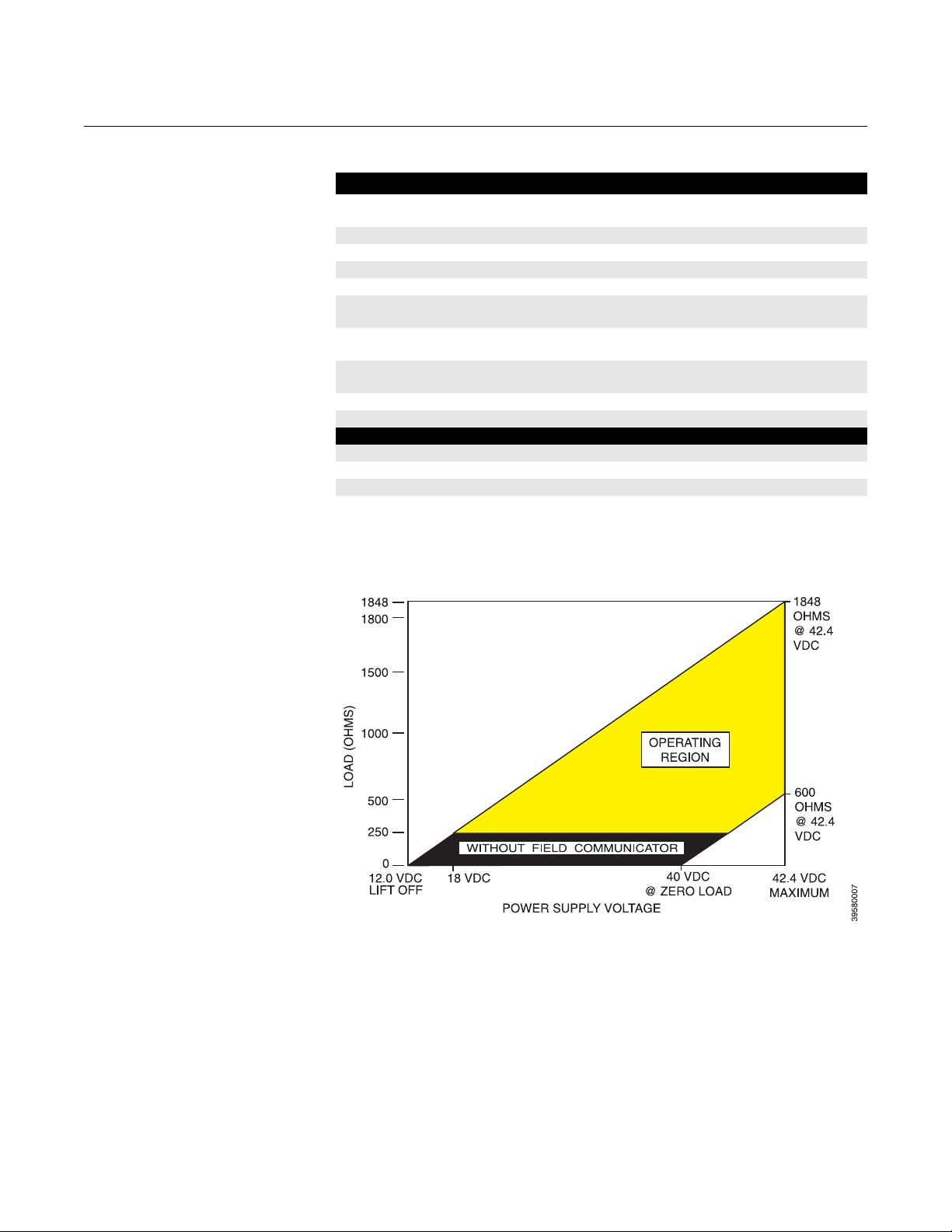
Power Supply and Load Requirements See Figure 1-4
Inputs (from O2 Probe) Two wires - O2 signal
Output One 4-20 mA signal with superimposed digital HART
Hazardous Area Certification ATEX EEx ia IIC T4 or T5
Power Transient Protection IEC 801-4
Shipping Weight 10 lbs (4,5 kg)
Infrared Remote Control
Power Requirements Three AAA Batteries
Hazardous Area Certification ATEX EEx ia IIC Class 1, Div 1, Group A, B, C, D
(1)
Thermocouple and O2 probe cell are both unpowered, developing a millivolt emf, and are
considered a "simple apparatus" by certifying agencies.
(2)
Dependent on ambient temperature limits.
corrosion-resistant
Two wires - type B thermocouple
signal
NEC Class 1 Div 1 Group B,C,D
(2)
Figure 1-4. Power Supply and
Load Requirements
1-8
Page 21
Instruction Manual
IM-106-5081, Rev. 2.0
October 2008
Table 1-1. Product Matrix
5081FG High Temperature Oxygen Flue Gas Analyzer
High Temperature Analyzer - Instruction Manual
Code Sensing Probe Type
1 20 in. (508 mm) probe, 1/4 in. tube fittings
2 26 in. (660 mm) probe, 1/4 in. tube fittings
3 38 in. (965 mm) probe, 1/4 in. tube fittings
Code Probe Outer Tube Material - Maximum Operating Temperature
1 Alumina - 2912°F (1600°C) maximum - 1.25 NPT mounting
2 Inconel Alloy - 1832°F (1000°C) maximum - 1.25 NPT mounting
Code Mounting Adapter- Stack Side
0 No adapter plate required uses 1.25 NPT
("0" must also be chosen under "Mounting Adapter" below)
1 New flanged installation - Square weld plate with studs (matches "Mounting Adapter" below)
2 Model 450 mounting ("4" must also be chosen under "Mounting Adapter" below)
3 Competitor's Mount ("5" must also be chosen under "Mounting Adapter" below)
Code Mounting Adapter - Probe Side
0 No adapter plate
1 ANSI 2 in. 150 lb flange to 1.25 NPT adapter
(6 in. dia. flange, 4.75 in. BC with 4 x 0.75 in. dia. holes)
2 DIN to 1.25 NPT adapter (184 mm flange, 145 mm BC with 4 x 18 mm dia. holes)
3 JIS to 1.25 NPT adapter (155 mm flange, 130 mm BC with 4 x 13 mm dia. holes)
4 Model 450 to 1.25 NPT adapter
5 Competitor's mounting flange
Code Electronics & Housing - Intrinsically Safe, NEMA 4X, IP65
1 5081 Electronics (Hart-compatible) - ATEX EEx ia IIC T5
2 5081 Electronics (Hart-compatible) - CSA pending
3 5081 Electronics (Hart-compatible) - FM Class 1, Div. 1, Groups B,C,D
Code Housing Mounting
1 Surface or wall mounting
2 1/2 to 2 in. pipe mounting
Code Communications
1 No remote control
2 Infrared Remote Control (IRC)
(LCD display through cover window
Code Calibration Accessories
1 No hardware
2 Calibration and reference air flowmeters and
reference air pressure regulator
Code Armored Cable Length
00 No cable
11 20 ft (6 m)
12 40 ft (12 m)
13 60 ft (18 m)
14 80 ft (24 m)
15 100 ft (30 m)
16 150 ft (45 m)
17 200 ft (61 m)
18 300 ft (91 m)
19 400 ft (122 m)
20 500 ft (152 m)
5081FG 2 1 0 0 1 1 1 2 11 Example
Model 5081FG
1-9
Page 22

Model 5081FG
Instruction Manual
IM-106-5081, Rev. 2.0
October 2008
1-10
Page 23
Instruction Manual
IM-106-5081, Rev. 2.0
October 2008
Section 2 Installation
Pre-Installation . . . . . . . . . . . . . . . . . . . . . . . . . . . . . . . . . . page 2-2
Mechanical Installation . . . . . . . . . . . . . . . . . . . . . . . . . . . page 2-2
Electrical Installation . . . . . . . . . . . . . . . . . . . . . . . . . . . . . page 2-11
Pneumatic Installation . . . . . . . . . . . . . . . . . . . . . . . . . . . . page 2-14
Before installing this equipment, read the "Safety instructions for the wiring and installation
of this apparatus" in Appendix A. Failure to follow safety instructions could result in serious
injury or death.
Model 5081FG
http://www.raihome.com
Page 24
Instruction Manual
IM-106-5081, Rev. 2.0
Model 5081FG
October 2008
PRE-INSTALLATION
Inspect Carefully inspect the shipping container for any evidence of damage. If the
container is damaged, notify the carrier immediately.
Packing List Confirm that all items shown on the packing list are present. Notify
Rosemount Analytical immediately if items are missing.
Before installing this equipment, read the "Safety instructions for the wiring and installation
of this apparatus" in Appendix A. Failure to follow safety instructions could result in serious
injury or death.
MECHANICAL INSTALLATION
Avoid installation locations near steam soot blowers.
Locating Oxygen Probe 1. The location of the oxygen probe in the stack or flue is important for
maximum accuracy in the oxygen analyzing process. The probe must
be positioned so the gas it measures is representative of the process.
Longer ducts may require several analyzers since the O
to stratification. A point too near the wall of the duct, or the in-side radius
of a bend, may not provide a representative sample because of the very
low flow conditions. The sensing point should be selected so the
process gas temperature falls within a range of 550° to 1400°C (1022°
to 2552°F). Figure 2-1 provides mechanical installation references.
2. Check the flue or stack for holes and air leakage. The presence of this
condition will substantially affect the accuracy of the oxygen reading.
Therefore, either make the necessary repairs or install the probe
upstream of any leakage.
3. Ensure the area is clear of internal and external obstructions that will
interfere with installation and maintenance access to the probe. Allow
adequate clearance for probe removal (Figure 2-1).
can vary due
2
2-2
Page 25
Instruction Manual
IM-106-5081, Rev. 2.0
October 2008
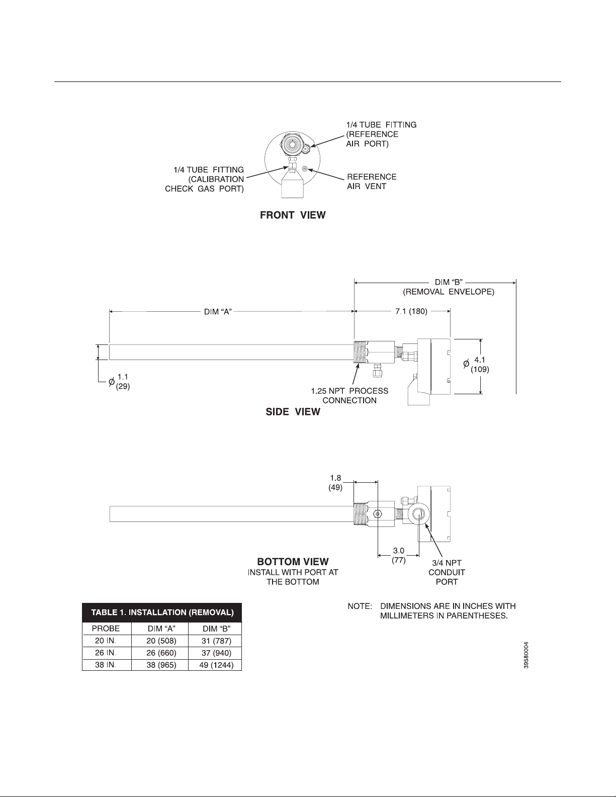
Figure 2-1. Probe Installation Details
Model 5081FG
2-3
Page 26
Model 5081FG
Installing Oxygen Probe
Instruction Manual
IM-106-5081, Rev. 2.0
October 2008
The probe was specially packaged to prevent breakage due to handling. Do not remove the
padding material from the probe until immediately before installation.
1. Ensure all components are available to install the probe.
NOTE
Leave the probe inner protective cover in place until installation. This is
required to protect the ceramic cell during movement.
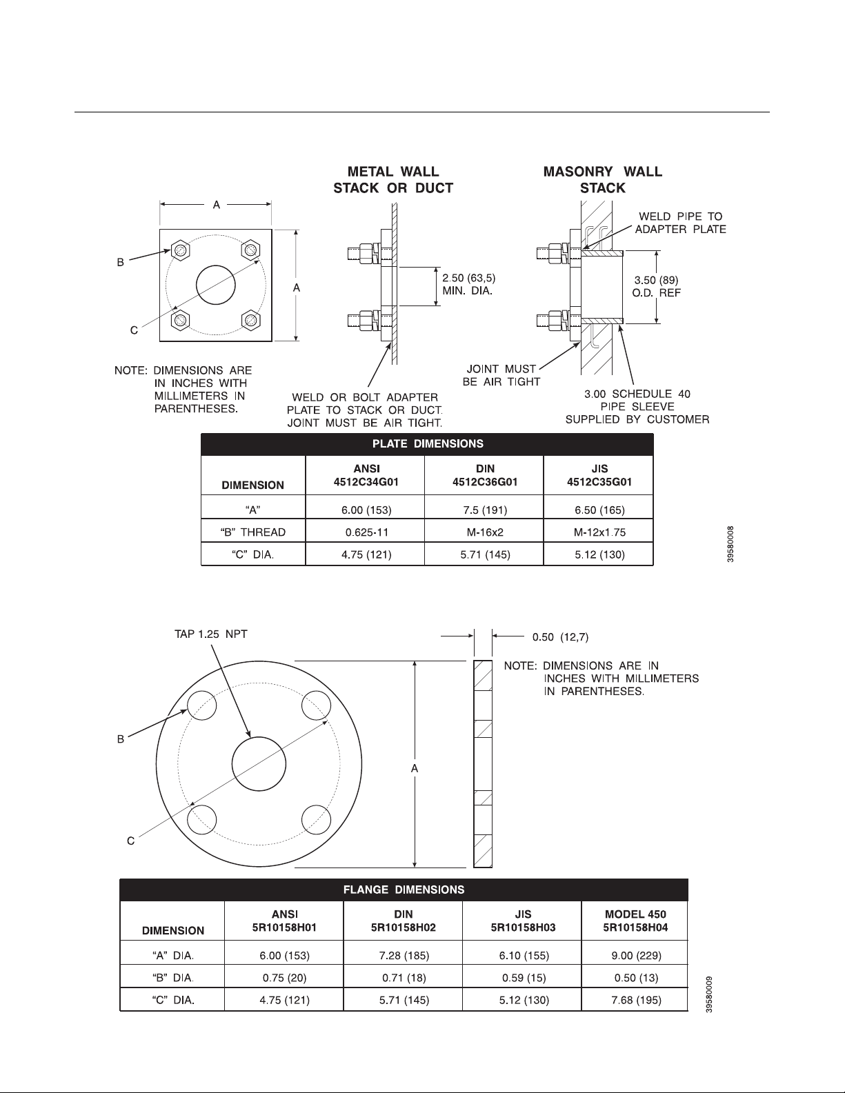
2. If using an optional adapter plate (Figure 2-2) or an optional mounting
flange (Figure 2-3), weld or bolt the component onto the duct. The
through hole in the stack or duct wall and refractory material must be
2 in. (50,8 mm) diameter, minimum.
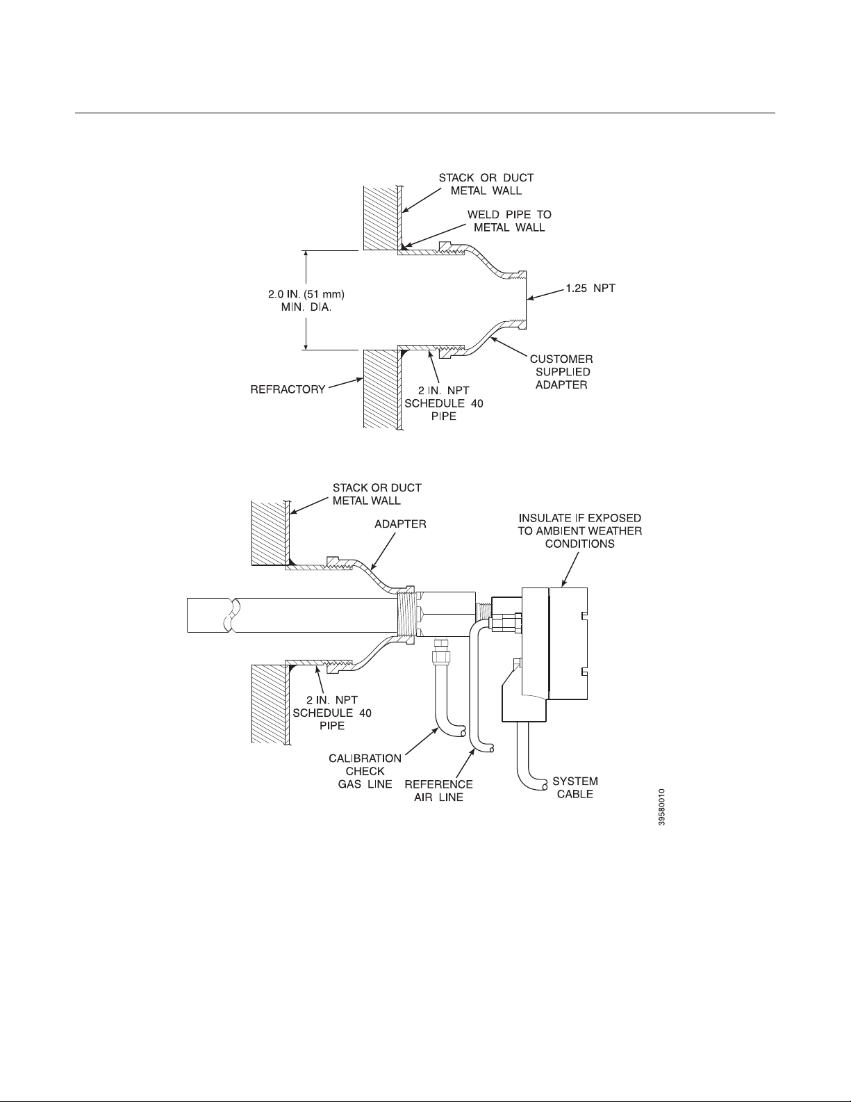
3. If the optional adapter plates are not used, a 2 in. NPT, schedule 40,
pipe nipple (Figure 2-4) should be welded to the stack or duct wall.
When a 2 in. NPT to 1.25 NPT adapter is threaded to the welded pipe
nipple, the adapter provides the pipe threads needed for the probe's
process fitting.
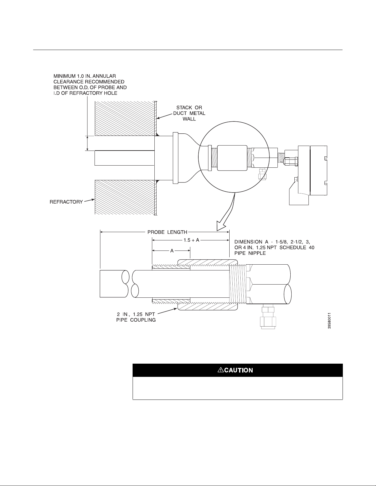
4. Where high particulate or slag is in the flue gas stream, it may be
desirable to inset the probe in the refractory as shown in Figure 2-5. Use
pipe couplings and nipples to adjust the probe insertion depth.
5. Use high temperature material (alumina wool) to seal around the probe
during insertion. This prevents hot gases from escaping or cold air from
entering the stack or duct.
6. Initially insert the probe to a depth of 3 in. (76,2 mm) or 1/2 the depth of
the stack or duct refractory, whichever is greater.
2-4
After initial insertion, do not insert the probe at a rate exceeding 1 in. per minute (25.4 mm
per minute) or damage to the probe may result due to thermal shock.
7. After initial insertion, insert the probe at a rate of 1 in. (25,4 mm) per
minute until the probe is fully inserted.
8. Install anti-seize compound on the pipe threads and screw the probe
into the process flange or adapter.
9. If insulation was removed to access the duct work for probe mounting,
make sure the insulation is replaced. See Figure 2-4.
If the ducts will be washed down during outage, MAKE SURE to power down the probes
and remove them from the wash area.
Page 27
Instruction Manual
IM-106-5081, Rev. 2.0
October 2008
Figure 2-2. Optional Adapter Plate
Model 5081FG
Figure 2-3. Optional Probe Mounting Flange
2-5
Page 28
Model 5081FG
Figure 2-4. Horizontal Probe Installation
Instruction Manual
IM-106-5081, Rev. 2.0
October 2008
2-6
Page 29
Instruction Manual
IM-106-5081, Rev. 2.0
October 2008
Figure 2-5. Adjusting Probe Insertion Depth
Model 5081FG
Locating Model 5081 Transmitter
1. Ensure the Model 5081 transmitter is easily accessible for maintenance
and service and for using the infrared remote control (if applicable).
Do not allow the temperature of the Model 5081 transmitter exceed 65°C (149°F) or
damage to the unit may result.
2. The ambient temperature of the transmitter housing must not exceed
65°C (149°F). Locate the electronics in an area where temperature
extremes, vibration, and electromagnetic and radio frequency
interference are minimal.
3. Locate the Model 5081 transmitter within 150 ft (45,7 m) of the oxygen
probe due to wiring and signal considerations.
2-7
Page 30
Model 5081FG
Instruction Manual
IM-106-5081, Rev. 2.0
October 2008
Installing Model 5081 Transmitter
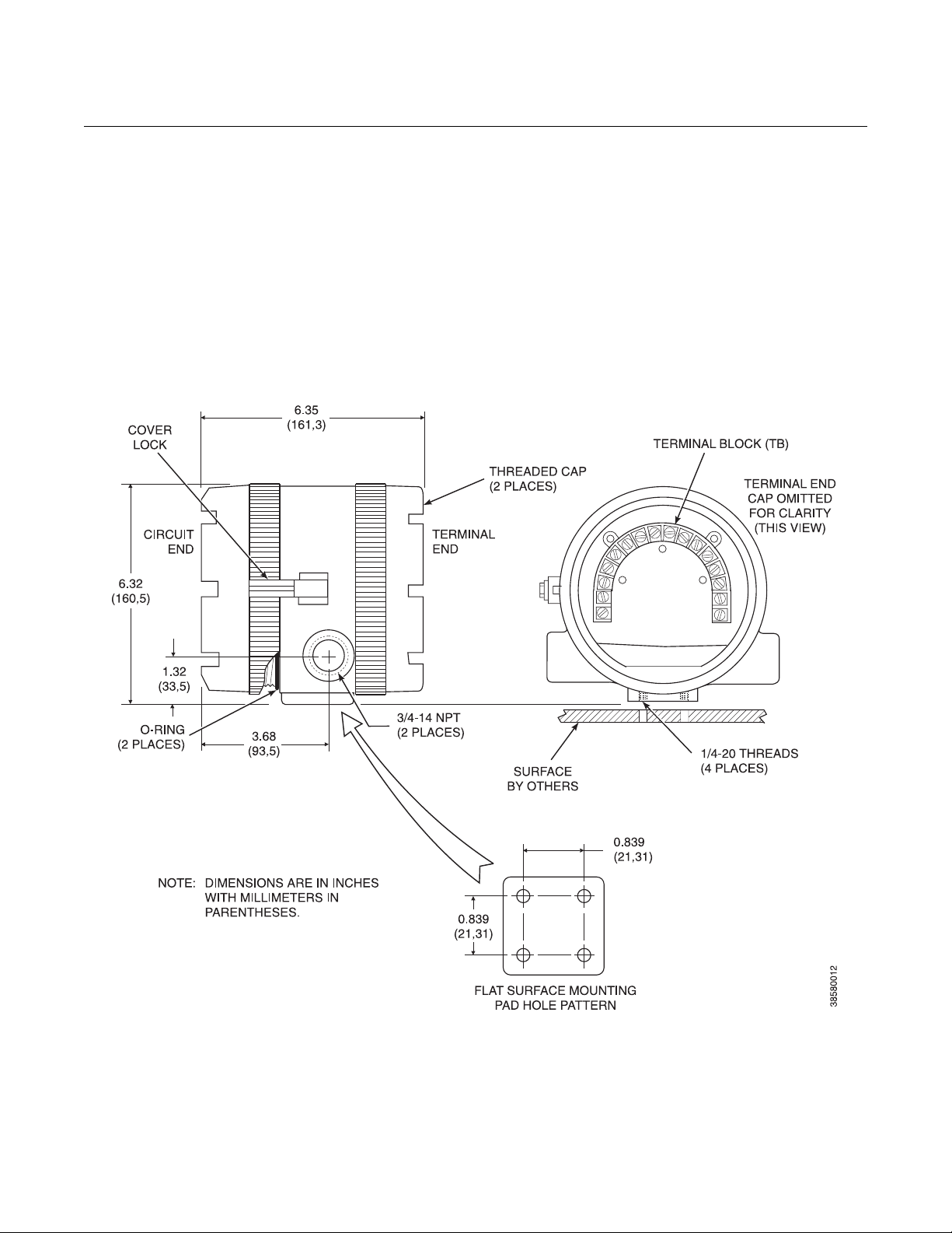
Figure 2-6. Flat Surface Mounting Dimensions
1. Ensure all components are available to install the Model 5081
transmitter.
2. Choose a method or location to mount the transmitter.
a. Flat Surface Mounting. The transmitter may be mounted on a flat
b. Pipe Mounting. An optional pipe mounting bracket is available for
surface using the threaded mounting holes located on the bottom of
the transmitter housing. Refer to Figure 2-6 for installation
references.
this type of installation. Refer to Figure 2-7 for installation references.
2-8
Page 31

Instruction Manual
IM-106-5081, Rev. 2.0
October 2008
Figure 2-7. Pipe Mounting Dimensions
Model 5081FG
2-9
Page 32

Model 5081FG
Figure 2-8. Display Positioning
Assembly
Instruction Manual
IM-106-5081, Rev. 2.0
October 2008
3. For correct viewing orientation, the display may be changed 90 degrees,
using the following procedure:
a. Refer to Figure 2-8. Loosen the cover lock screw until the cover lock
is disengaged from the knurled surface on the threaded circuit end
cap.
b. Remove the circuit end cap.
c. Remove the three screws retaining the display board in place.
d. Lift and rotate the display board 90 degrees either way.
e. Reposition the display board on the standoffs. Install and tighten all
three screws.
f. Install the circuit end cap and tighten the cover lock screw to secure
the cover lock in place.
2-10
Page 33

Instruction Manual
IM-106-5081, Rev. 2.0
October 2008
Model 5081FG
ELECTRICAL INSTALLATION
All wiring must conform to local and national codes.
For intrinsically safe applications, refer to the installation drawings in Appendix C of this
Instruction Manual.
Disconnect and lock out power before connecting the unit to the power supply.
Install all protective equipment covers and safety ground leads after installation. Failure to
install covers and ground leads could result in serious injury or death.
To meet the Safety Requirements of IEC 1010 (EC requirement), and ensure safe operation
of this equipment, connection to the main electrical power supply must be made through a
circuit breaker (min 10 A) which will disconnect all current-carrying conductors during a fault
situation. This circuit breaker should also include a mechanically operated isolating switch.
If not, then another external means of disconnecting the supply from the equipment should
be located close by. Circuit breakers or switches must comply with a recognized standard
such as IEC 947.
General The power supply and signal wiring should be shielded. Also, make sure the
signal wiring is grounded at the Model 5081 transmitter end only. Do not
ground the signal loop at more than one point. Twisted pairs are
recommended. Ground the transmitter housing to an earth ground to prevent
unwanted electromagnetic interference (EMI) or radio frequency interference
(RFI).
NOTE
For optimum EMI/RFI immunity, shield the 4-20 mA current loop cable and
enclose in an earth grounded metal conduit.
NOTE
Never run signal or sensor wiring in the same conduit, or open tray, with
power cables. Keep signal or sensor wiring at least 12 in. (0,3 m) away from
other electrical equipment and 6.5 ft (2 m) from heavy electrical equipment.
2-11
Page 34

Model 5081FG
Instruction Manual
IM-106-5081, Rev. 2.0
October 2008
Moisture accumulation in the transmitter housing can affect its performance and may void
its warranty.
It is necessary to prevent moisture from entering the Model 5081 transmitter
housing. The use of weather-tight cable glands is required. If conduit is used,
plug and seal connections on the transmitter housing to prevent moisture
accumulation in the terminal side of the housing.
Oxygen Probe Signal Connections
Figure 2-9. Oxygen Probe
Terminal Block
1. Two signals represent the O2 value and the cell temperature. The probe
provides these values to the Model 5081 transmitter for processing and
signal conditioning.
2. Wiring connections for the probe are shown in Figure 2-9.
2-12
Page 35

Instruction Manual
IM-106-5081, Rev. 2.0
October 2008
Model 5081FG
Model 5081 Transmitter 4-20 mA and Signal Connections
Figure 2-10. Transmitter
Terminal Block
1. A 4-20 mA signal represents the O2 value. Superimposed on the
4-20 mA signal is HART information that is accessible through a
HART field communicator or AMS software.
2. Two signals representing the O
supplied to the Model 5081 transmitter from the oxygen probe.
3. Wiring connections for the Model 5081 transmitter are shown in
Figure 2-10.
NOTE
The ground arrangement shown in Figure 2-10 limits the amount of noise
introduced into the electronics.
4. Connect wire shields to terminal 1. Connect earth ground as shown.
value and the cell temperature are
2
2-13
Page 36

Model 5081FG
PNEUMATIC INSTALLATION
Instruction Manual
IM-106-5081, Rev. 2.0
October 2008
General Reference air is required for O
required during a calibration check. Refer to Figure 2-11 for the gas
connections on the oxygen probe.
calculation, and calibration check gas is
2
Reference Air Package After the oxygen probe is installed, connect the reference air set. Install the
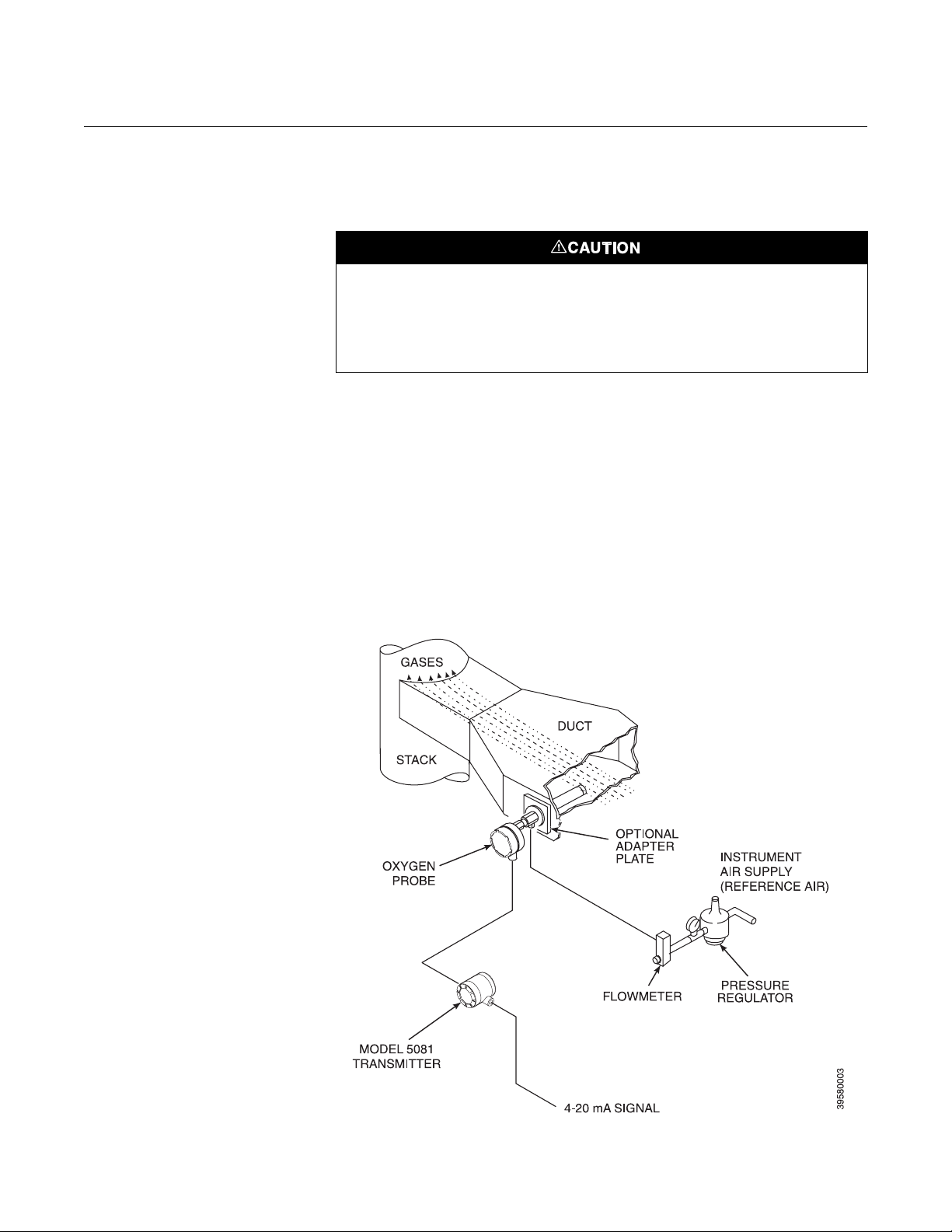
reference air set according to Figure 2-11.
Instrument Air (Reference Air)
Figure 2-11. Air Set, Plant Air Connections
Instrument air is required for reference. Refer to the reference air schematic,
Figure 2-12. Use 10 psig (68,95 kPa gage) minimum, 225 psig (1551,38 kPa
gage) at 0.2 scfh (100 m
hydrocarbons. Regulator outlet pressure should be set at 5 psi (35 kPa).
/min.); less than 40 parts-per-million total
Figure 2-12. Reference Air Schematic
2-14
Page 37

Instruction Manual
IM-106-5081, Rev. 2.0
October 2008
Model 5081FG
Calibration Gas Two calibration check gas concentrations are used with the Two-Wire In Situ
Oxygen Analyzer: Low Gas - 0.4% O
balance in nitrogen.
and High Gas - 8% O2, each with the
2
Figure 2-13. Gas Connections at
Oxygen Probe
Do not use 100% nitrogen as a low gas (zero gas). It is suggested that gas for the low (zero)
be between 0.4% and 2.0% O
than 40 parts per million. Failure to use proper gases will result in erroneous readings.
. Do not use gases with hydrocarbon concentrations of more
2
Do not use 100% nitrogen for the low (zero %) check gas. See Figure 2-13 for
the probe connections. Set both calibration check gases at the same flow
rate: 5 scfh (2,5
/min).
2-15
Page 38

Model 5081FG
Instruction Manual
IM-106-5081, Rev. 2.0
October 2008
2-16
Page 39

Instruction Manual
IM-106-5081, Rev. 2.0
October 2008
Section 3 Startup and Operation
General . . . . . . . . . . . . . . . . . . . . . . . . . . . . . . . . . . . . . . . . page 3-1
Power Up . . . . . . . . . . . . . . . . . . . . . . . . . . . . . . . . . . . . . . . page 3-1
Establishing Proper Calibration Gas Flow Rate . . . . . . .page 3-3
Operation . . . . . . . . . . . . . . . . . . . . . . . . . . . . . . . . . . . . . . . page 3-4
Program Menu . . . . . . . . . . . . . . . . . . . . . . . . . . . . . . . . . . . page 3-7
Diagnostics Menu . . . . . . . . . . . . . . . . . . . . . . . . . . . . . . . . page 3-16
Cal Check Menu . . . . . . . . . . . . . . . . . . . . . . . . . . . . . . . . . page 3-21
GENERAL
Install all protective equipment covers and safety ground leads before equipment startup.
Failure to install covers and ground leads could result in serious injury or death.
Model 5081FG
Verify Mechanical Installation
Ensure the Two-Wire In Situ Oxygen Analyzer is installed correctly. See
Mechanical Installation in Section 2: Installation for mechanical installation
information.
Verify Terminal Block Wiring
Ensure the wiring of both the oxygen probe terminal block and Model 5081
transmitter terminal block is correct. Refer to Electrical Installation in
Section 2: Installation for electrical installation and wiring information.
POWER UP General
The Two-Wire In Situ Oxygen Analyzer displays the current oxygen reading
on the LCD face of the Model 5081 transmitter. The O
temperature, and 4-20 mA output current are displayed as shown in
Figure 3-1. This and other information may also be accessed using
HART/AMS.
Startup Display
When the probe is first inserted into the stack, some time is required until the
minimum operating temperature [550°C (1022°F)] is reached. Some time is
also required for the electronics to reach an operating state. Therefore, when
the unit is first powered up, a faulted operation display as shown in Figure 3-2
may be displayed by the transmitter until the probe operating temperature is
reached and the electronics are working properly (approximately 5 minutes).
concentration, cell
2
http://www.raihome.com
Page 40

Model 5081FG
Instruction Manual
IM-106-5081, Rev. 2.0
October 2008
Operating Display
After the probe has reached operating temperatures, the Model 5081
transmitter display should look similar to Figure 3-1. The display will now track
the O
concentration, cell temperature, and 4-20 mA output current.
2
Figure 3-1. Normal Operation
Display
Figure 3-2. Faulted Operation
Display
3-2
Page 41

Instruction Manual
IM-106-5081, Rev. 2.0
October 2008
Model 5081FG
ESTABLISHING PROPER CALIBRATION GAS FLOW RATE
Figure 3-3. Proper Calibration Check Gas Flow Rate
The calibration gas flow must be enough to ensure that no combustion flue
gases mix with the calibration check gases and only clean, good calibration
check gas surrounds the cell without expending excess gas (Figure 3-3).
Monitor the O
calibration check gas flow rate as follows:
NOTE
Only set the calibration check gas flow rate at startup. It is not necessary to
perform this procedure for each calibration check.
1. Adjust the calibration check gas flow to 5 scfh (2,5
cell is surrounded by calibration check gas. Due to the cooling effect of
the gas, the cell temperature will decrease slightly, causing the O
concentration to drop. Once the electronics compensates for this effect,
the O
2. Next, slowly reduce the calibration check gas flow until the O
concentration changes, which indicates that the calibration check and
flue gases are mixing. Increase the flow rate until this effect is
eliminated.
2
concentration will stabilize.
2
concentration using an IRC or a field communicator. Set the
/min.) to ensure the
2
2
3-3
Page 42

Instruction Manual
IM-106-5081, Rev. 2.0
Model 5081FG
October 2008
OPERATION
Overview This section explains the operator controls and displays of the Two-Wire In
Situ Oxygen Analyzer. The use of the Infrared Remote Control (IRC) and the
Model 5081 transmitter Liquid Crystal Display (LCD) are described in detail.
HART/AMS operation is not covered here. Refer to Section 4: HART/AMS.
Display The LCD on the circuit end of the Model 5081 transmitter displays O
concentration, cell temperature, and 4-20 mA output current during normal
operation (Figure 3-4). The LCD will also display fault conditions when they
occur. To interact with the transmitter, use the IRC and navigate through a
series of menus displayed on the LCD.
2
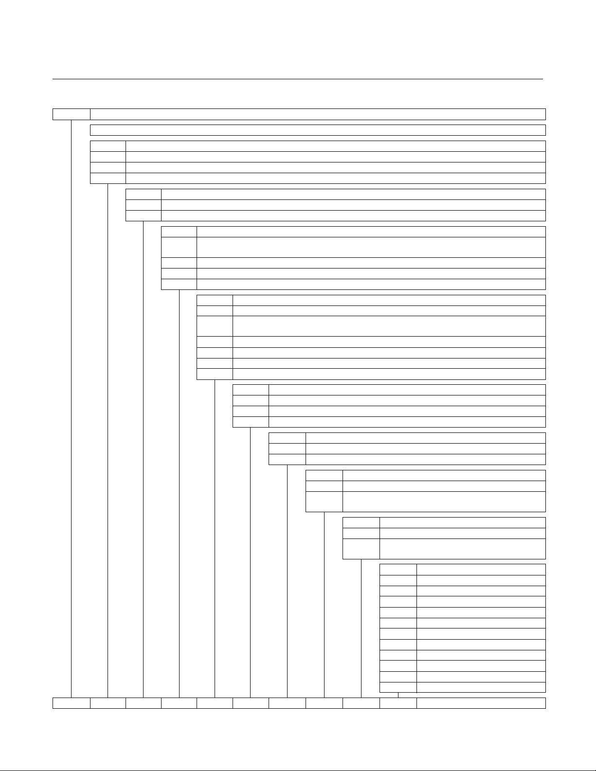
Menu Tree The screens that can be displayed are shown in the menu tree of Figure 3-5.
These screens are displayed on the LCD and are accessed using the IRC
keypad.
Figure 3-4. Normal Operation Display
3-4
Page 43

Instruction Manual
IM-106-5081, Rev. 2.0
October 2008
Figure 3-5. Transmitter Menu Tree
Model 5081FG
3-5
Page 44

Instruction Manual
IM-106-5081, Rev. 2.0
Model 5081FG
October 2008
Navigation The IRC in Figure 3-6 is used to interact with the Model 5081 transmitter and
navigate through the screens on the LCD.
1. Hold the IRC within 6 ft (1,8 m) of the Model 5081 transmitter and within
15 degrees from the centerline of the transmitter LCD. The amount of
ambient light may also affect IRC performance:
NOTE
The LCD may react slowly to IRC commands. Allow sufficient time between
key presses to avoid undesired or repeated commands from accumulating in
the command queue.
2. Use the keys on the IRC to navigate through the menu screens. Refer to
Figure 3-6. General usage is as follows:
a. RESET. Returns to the PROCESS DISPLAY screen at the top of the
menu tree. Any non-entered number in the exited state will be
ignored, and the previous data will be used.
b. HOLD. Not used.
c. Left/Right Arrow. Moves left and right among editable digits on the
display.
d. Up/Down Arrow. Increases or decreases the value of the currently
selected digit on the display.
e. CAL. Accesses the CALCHECK MENU branch of the menu tree.
Only works from the PROCESS DISPLAY screen.
Figure 3-6. Infrared Remote
Control (IRC)
3-6
Page 45

Instruction Manual
IM-106-5081, Rev. 2.0
October 2008
Model 5081FG
f. PROG. Accesses the PROGRAM MENU branch of the menu tree.
Only works from the PROCESS DISPLAY screen.
g. DIAG. Accesses the DIAGNOSTICS MENU branch of the menu
tree. Only works from the PROCESS DISPLAY screen.
h. ENTER. Initiates the editing process and causes the most
significant digit of the edited item to start flashing. Also processes the
entry so the previous value updates to the new value entered using
the arrow keys. Failure to press ENTER before exiting a screen will
cancel the input value and revert to the previous value.
i. NEXT. Accesses the next user screen as shown in the menu tree.
Any non-entered number in the exited state will be ignored, and the
previous data will be used.
j. EXIT. Exits from sub-branches of the menu tree where an exit option
is explicitly shown. Otherwise, returns to the PROCESS DISPLAY
screen at the top of the menu tree. Any non-entered number in the
exited state will be ignored, and the previous data will be used.
PROGRAM MENU The PROGRAM MENU branch of the menu tree allows you to program and
edit some process parameters, faults, outputs, and security codes. To access
this branch of the menu tree, press the PROG key on the IRC when in the
PROCESS DISPLAY screen (Normal or Faulted). If security is enabled, you
must enter the analyzer code to gain further access to the screens in this
branch. Each screen in this branch is accessed sequentially using the NEXT
key. Refer to Figure 3-5 during the following menu and screen descriptions.
NOTE
To edit a screen value, press ENTER to access the data field. Use the left and
right arrow keys to move among the digits in the data field. Note that the
editable position will be flashing. To change the value of a digit, use the up
and down arrow keys to increase or decrease the value. When finished
editing, press ENTER to accept the value. To go to the next screen in the
menu, press NEXT.
Operator Adjustable Parameters
Figure 3-1 lists the range and default value of operator-adjustable variables
used by the Model 5081 transmitter. Each of these variables may be adjusted
using the PROGRAM MENU screens.
Table 3-1. Adjusatble
Parameters
Parameter Function Range Factory Default
CODE Use to enter the access code for this analyzer; select 555
FAULT VAL Use to designate a 4-20mA value that when displayed
UPPER RANGE VAL Use to set upper O
CELL T HI Use to set upper cell temperature for no-fault condition 650°C - 1600°C 1600°C
SET O2 FILTER TIME Use to adjust analyzer response time to changing O
SET HI BOTTLE O2 Use to define actual O2% of high calibration check gas 8%
SET LO BOTTLE O2 Use to define actual O
SET CODE Use to set security code for this analyzer 000 - 999 (excluding 000 and 555) 000 (no code)
to display designated analyzer code
will indicate an analyzer-faulted condition
% limit equivalent to 20mA output
(adjust the slope of the analyzer)
2
% of low calibration check gas 2%
2
000 - 999 (excluding 000 and 555) 000 (no code)
3.8mA - 24mA 3.6mA
2.0% - 25.0% 25%
% 0 - 300 seconds 0 seconds
2
3-7
Page 46

Instruction Manual
IM-106-5081, Rev. 2.0
Model 5081FG
October 2008
Code Refer to Figure 3-7. After pressing the PROG key, this screen will display if
security is enabled (see Set Code). Use this screen to identify a specific
analyzer in a process to prevent accessing an adjacent analyzer when using
the IRC.
Press ENTER to begin editing. At this point, you can either specify the
analyzer by its access code or view its code if it is unknown.
1. To gain further access to the screens in the PROGRAM MENU branch,
enter the correct three-digit analyzer access code using the arrow keys
and press ENTER. If security is disabled, this screen does not appear
and the system displays the FAULT VAL screen.
2. If the analyzer access code is un-known, enter 555 and press ENTER to
access the DISPLAY CODE screen. In that screen you will be able to
view the analyzer access code.
Figure 3-7. Code
3-8
Page 47

Instruction Manual
IM-106-5081, Rev. 2.0
October 2008
Model 5081FG
Display Code Refer to Figure 3-8. This screen is accessible from the CODE screen by
entering 555 and pressing ENTER. The DISPLAY CODE screen identifies the
analyzer access code so you can return to the CODE screen and enter the
code as described in Code. To return to the CODE screen, press NEXT.
Fault Val Refer to Figure 3-9. Use this screen to set the value that the 4-20 mA output
will drive to and display during a fault condition. Press ENTER to begin
editing. Use the arrow keys to enter a fault value. The fault value can be
between 3.8 and 24 mA. Then, press ENTER to accept the value. Pressing
NEXT displays the UPPER RANGE VAL screen. Refer to Section 5:
Troubleshooting, for the actual fault conditions.
Figure 3-8. Display Code
Figure 3-9. Fault Val
3-9
Page 48

Instruction Manual
IM-106-5081, Rev. 2.0
Model 5081FG
October 2008
Upper Range Val Refer to Figure 3-10. Use this screen to set the value of the upper range limit.
This value is the maximum limit of the O
used to scale the 4-20 mA output. Press ENTER to begin editing. Use the
arrow keys to select and change the value. The upper range value can be
between 0 and 25%. Then, press ENTER to accept the value. Pressing NEXT
displays the CELL T HI screen.
concentration measurement and is
2
Cell T Hi Refer to Figure 3-11. Use this screen to set the value of the upper cell
temperature fault condition. This value is the maximum allowed cell
temperature before a fault condition is indicated. Press ENTER to begin
editing. Use the arrow keys to select and change the value. The value must
be between 550° and 1600°C. Press ENTER to accept the value. Pressing
NEXT displays the RESET MAX CELL T screen.
Figure 3-10. Upper Range Val
Figure 3-11. Cell T Hi
3-10
Page 49

Instruction Manual
IM-106-5081, Rev. 2.0
October 2008
Model 5081FG
Reset Max Cell T Refer to Figure 3-12. The transmitter tracks the maximum cell temperature
obtained. Use this screen to reset the maximum cell temperature attained
value to the current cell temperature. Press ENTER to begin editing. Use the
arrow keys to select and change the value (Y/N). Then, press ENTER to
accept the value. Pressing NEXT displays the SET O
FILTER TIME screen.
2
Set O2 Filter Time Refer to Figure 3-13. In some applications it is beneficial to dampen the raw
O
signal coming from the cell. Use this screen to enter the amount of time it
2
will take the O
editing. Use the arrow keys to select and change the screen value to the O
filter value (in seconds). Enter a value between 0 and 300 seconds and press
ENTER to accept the value. Press NEXT to access the TRIM 4 mA? screen.
to reach 90% of the new reading. Press ENTER to begin
2
2
Figure 3-12. Reset Max Cell T
Figure 3-13. Set O2 Filter Time
3-11
Page 50

Instruction Manual
IM-106-5081, Rev. 2.0
Model 5081FG
October 2008
Trim 4mA? Refer to Figure 3-14. Use this screen to trim the 4 mA value of the 4-20 mA
output.
NOTE
Before trimming the 4 mA value you must break the loop to add the ammeter.
Power down the unit, connect the ammeter in series with Model 5081
transmitter terminals 15(-) and 16(+), power up the unit, and return to the
TRIM 4 mA? screen.
Press ENTER to begin editing. Use the arrow keys to select and change the
screen value to the value displayed on the installed ammeter. Press ENTER
to accept the value. After the value is entered, the unit calibrates itself to
ensure it outputs 4 mA. Both the display and the ammeter will display 4 mA.
Pressing EXIT returns to the initial TRIM 4 mA? screen, and pressing NEXT
displays the TRIM 20 mA? screen.
Figure 3-14. Trim 4mA?
3-12
Page 51

Instruction Manual
IM-106-5081, Rev. 2.0
October 2008
Model 5081FG
Trim 20mA? Refer to Figure 3-15. Use this screen to trim the 20 mA value of the 4-20 mA
output.
NOTE
Before trimming the 20 mA value you must break the loop to add the
ammeter. Power down the unit, connect the ammeter in series with Model
5081 transmitter terminals 15(-) and 16(+), power up the unit, and return to
the TRIM 20 mA? screen.
Press ENTER to begin editing. Use the arrow keys to select and change the
screen value to the value displayed on the installed ammeter. Press ENTER
to accept the value. After the value is entered, the unit calibrates itself to
ensure it outputs 20 mA. Both the display and the ammeter will display 20 mA.
Pressing EXIT returns to the initial TRIM 20 mA? screen, and pressing NEXT
displays the SET HI BOTTLE O
screen.
2
Figure 3-15. Trim 20mA?
3-13
Page 52

Instruction Manual
IM-106-5081, Rev. 2.0
Model 5081FG
October 2008
Set Hi Bottle O2 Refer to Figure 3-16. Use this screen to identify, within the electronics, the
percentage of O
begin editing. Use the arrow keys to select and change the screen value to
the O
percentage of the high calibration check gas. Press ENTER to accept
2
the value.
used as the high calibration check gas. Press ENTER to
2
Set Lo Bottle O
2
Figure 3-16. Set Hi Bottle O
Refer to Figure 3-17. Use this screen to identify, within the electronics, the
percentage of O
used as the low calibration check gas. Press ENTER to
2
begin editing. Use the arrow keys to select and change the screen value to
the O
percentage of the low calibration check gas. Press ENTER to accept
2
the value. Press NEXT to display the SET O
2
TRACKING screen.
2
Figure 3-17. Set Lo Bottle O
3-14
2
Page 53

Instruction Manual
IM-106-5081, Rev. 2.0
October 2008
Model 5081FG
Set O2 Tracking Refer to Figure 3-18. Use this screen to permit the 4-20 mA line to track the
value during a calibration check. Press ENTER to begin editing. Use the
O
2
arrow keys to select Y or N. Entering Y (yes) will allow the 4-20 mA line to
track the O
O
value steady during the calibration check. Press ENTER to accept the
2
value during the calibration check. Entering N (no) will hold the
2
value. Press NEXT to display the SET CODE screen.
Set Code Refer to Figure 3-19. Use this screen to set the security code for the Model
5081 transmitter. Press ENTER to begin editing. Use the arrow keys to select
and change the value. Select any value between 000 and 999, excluding 000
and 555. Code 000 indicates that no code is set. Code 555 accesses the
DISPLAY CODE screen. Press ENTER to accept the value. Pressing NEXT
returns to the FAULT VAL screen at the beginning of the PROGRAM MENU.
Figure 3-18. Set O
Tracking
2
Figure 3-19. Set Code
3-15
Page 54

Instruction Manual
IM-106-5081, Rev. 2.0
Model 5081FG
October 2008
DIAGNOSTICS MENU The DIAGNOSTICS MENU branch of the menu tree allows you to examine
outputs, current faults, and unit information. None of the items in the
DIAGNOSTICS MENU are editable. This branch of the menu tree may be
accessed by pressing DIAG on the IRC when in the PROCESS DISPLAY
screen (Normal or Faulted). Each screen in this branch is accessed
sequentially by pressing NEXT. Refer to the menu in Figure 3-5 when
reviewing the following menu and screens.
Show Fault Refer to Figure 3-20. After pressing DIAG, this screen displays. Pressing
ENTER accesses a screen displaying the current fault (if any). If more than
one fault exists, and you are in the FAULT screen, press NEXT to go to the
next fault. Information on the fault screens can be found in Section 5:
Troubleshooting. Press EXIT to return from this fault sub-menu and press
NEXT to access the T/C mV screen.
Figure 3-20. Show Fault
3-16
Page 55

Instruction Manual
IM-106-5081, Rev. 2.0
October 2008
Model 5081FG
T/C mV Refer to Figure 3-21. Use this screen to examine the cell thermocouple mV
output. Three decimal places are displayed. Pressing NEXT accesses the O
CELL mV screen.
2
O2 CELL mV Refer to Figure 3-22. Use this screen to examine the O
Pressing NEXT accesses the CELL IMPEDANCE screen.
Figure 3-21. T/C mV
CELL mV output.
2
Figure 3-22. O2 CELL mV
3-17
Page 56

Model 5081FG
Instruction Manual
IM-106-5081, Rev. 2.0
October 2008
Cell Impedance Refer to Figure 3-23. Use this screen to examine the O
status. GOOD indicates the cell is operating normally. WARN indicates the
cell has degraded but is still operational. HI indicates that the cell has
degraded but is still operational; however, failure will occur soon. Pressing
NEXT accesses the CURRENT SLOPE screen.
NOTE
Temperature influences cell impedance. Wait until the cell is at operating
temperature before checking cell impedance. If checked before the cell
reaches 550°C (1022°F), this screen displays a fail indication.
cell impedance
2
Current Slope Refer to Figure 3-24. Use this screen to examine the slope calculated from
the most recent calibration check. The slope is the amount of cell voltage
Figure 3-23. Cell Impedance
generated for a given O
over the life of the probe. Tracking the slope will indicate if the probe is
degrading. Press NEXT to access the CURRENT CONSTANT screen.
value. For each calibration check, record the slope
2
Figure 3-24. Current Slope
3-18
Page 57

Instruction Manual
IM-106-5081, Rev. 2.0
October 2008
Model 5081FG
Current Constant Refer to Figure 3-25. Use this screen to examine the cell zero constant
calculated from the most recent calibration check. The constant represents
the voltage generated by the cell when no difference exists between the
amount of O
access the PREVIOUS SLOPE screen.
on the reference and process sides of the cell. Press NEXT to
2
Previous Slope Refer to Figure 3-26. Use this screen to examine the slope value stored from
the second to last calibration check. The slope is the amount of cell voltage
Figure 3-25. Current Constant
generated for a given O
over the life of the probe. Tracking the slope will indicate if the probe is
degrading. Press NEXT to access the PREVIOUS CONSTANT screen.
value. For each calibration check, record the slope
2
Figure 3-26. Previous Slope
3-19
Page 58

Instruction Manual
IM-106-5081, Rev. 2.0
Model 5081FG
October 2008
Previous Constant Refer to Figure 3-27. Use this screen to examine the cell zero constant stored
from the second to last calibration check. The constant represents the voltage
generated by the cell when no difference exists between the amount of O
the reference and process sides of the cell. Press NEXT to access the MAX
CELL T screen.
2
on
Max Cell T Refer to Figure 3-28. Use this screen to examine the maximum temperature
attained by the O
Pressing NEXT accesses the SW VER screen.
cell. This value can be reset under the PROGRAM MENU.
2
Figure 3-27. Previous Constant
Figure 3-28. Max Cell T
3-20
Page 59

Instruction Manual
IM-106-5081, Rev. 2.0
October 2008
Model 5081FG
SW Ver (SOFt) Use this screen to see the software version number for the Model 5081
transmitter. Pressing NEXT accesses the UNIT SER # screen.
Unit Ser # (SEr) Use this screen to see the unit serial number for the Model 5081 transmitter.
Pressing NEXT accesses the SW BUILD NUMBER screen.
SW Build Number (bLdn) Use this screen to see the software build number for the Model 5081
transmitter. Pressing NEXT accesses the SW BUILD DATE screen.
SW Build Date (bd) Use this screen to see the software build date for the Model 5081 transmitter.
Pressing NEXT returns to the beginning of the DIAGNOSTICS MENU branch
(the SHOW FAULT screen).
CAL CHECK MENU The CALCHECK MENU branch of the menu tree (Figure 3-5) allows you to
perform a calibration check of the analyzer. Before performing a calibration
check, ensure the high calibration check gas and low calibration check gas O
percentages are entered into the electronics via the PROGRAM MENU. To
set these values, refer to Set Hi Bottle O2 and Set Lo Bottle O2.
Once these values are set, access the CAL-CHECK MENU branch by
pressing CAL on the IRC when in the PROCESS DISPLAY screen (Normal or
Faulted). Each screen in this branch identifies a process step in the
calibration check procedure. The first screen in the sequence is the IN
MANUAL? screen.
2
In Manual?
Figure 3-29. In Manual?
Failure to remove the analyzer from automatic control loops prior to performing this
procedure may result in a dangerous operating condition.
Refer to Figure 3-29. If the O2 output value is used in any automatic process
control loops the loop must be placed in manual to begin a calibration check.
Once the analyzer is removed from any automatic control loops press ENTER
to edit the screen. Use the arrow keys to select Y (yes); press ENTER to start
a calibration check and to display the ACCEPT HIGH O
screen.
2
3-21
Page 60

Model 5081FG
Instruction Manual
IM-106-5081, Rev. 2.0
October 2008
Accept High O
Accept Low O
2
2
Figure 3-30. Accept High O
Refer to Figure 3-30. After pressing ENTER to begin the calibration check, the
high calibration check gas starts to flow. After waiting approximately three
minutes for the displayed O
value to settle, press NEXT to accept the high
2
calibration check gas reading and apply the low calibration check gas. The
next screen to display is the ACCEPT LOW O
screen.
2
Refer to Figure 3-31. Once the low calibration check gas is applied, wait
approximately three minutes for the displayed O
value to settle. Once the
2
value settles, press NEXT to accept the reading and to display the SLOPE
screen.
2
Figure 3-31. Accept Low O
2
3-22
Page 61

Instruction Manual
IM-106-5081, Rev. 2.0
October 2008
Model 5081FG
Slope Refer to Figure 3-32. Use this screen to examine the slope calculated from
current calibration check. The slope is the amount of cell voltage generated
for a given O
life of the probe. Tracking the slope will indicate if the probe is degrading.
Press NEXT to access the CONSTANT screen.
value. After each calibration check, record the slope over the
2
Constant Refer to Figure 3-33. Use this screen to examine the cell zero constant
calculated from the current calibration check. The constant represents the
voltage generated by the cell when no difference exists between the amount
of O
on the reference and process sides of the cell. Note this value for
2
comparison against future calibration checks. Press RESET or EXIT to return
to the PROCESS DISPLAY screen.
Figure 3-32. Slope
Figure 3-33. Constant
3-23
Page 62

Model 5081FG
Instruction Manual
IM-106-5081, Rev. 2.0
October 2008
3-24
Page 63

Instruction Manual
IM-106-5081, Rev. 2.0
October 2008
Model 5081FG
Section 4 HART/AMS
Overview . . . . . . . . . . . . . . . . . . . . . . . . . . . . . . . . . . . . . . . page 4-1
Field Communicator Signal Line Connections . . . . . . . . page 4-2
Field Communicator PC Connections . . . . . . . . . . . . . . . page 4-4
Off-Line and On-Line Operations . . . . . . . . . . . . . . . . . . . page 4-4
HART/AMS Menu Tree . . . . . . . . . . . . . . . . . . . . . . . . . . . . page 4-4
Field Communicator Start Cal Check Method . . . . . . . . . page 4-8
OVERVIEW The HART field communicator is a handheld communications interface
device. It provides a common communications link to all microprocesor-based
instruments that are HART compatible. The field communicator has a liquid
crystal display (LCD) and keypad. A pocket-sized manual, included with the
field communicator, details the specific functions of the keypad keys.
To interface with the Model 5081FG Analyzer, the field communicator requires
a termination point along the 4-20 mA current loop and a minimum load resistance of 250 ohms between the field communicator and the power supply.
The field communicator accomplishes its task using a frequency shift keying
(FSK) technique. With the use of FSK, high-frequency digital communication
signals are superimposed on the analyzer's 4-20 mA current loop. The field
communicator does not disturb the 4-20 mA signal, since no net energy is
added to the loop.
The field communicator may be interfaced with a personal computer (PC),
providing that special software has been installed. To connect the field communicator to a PC, an interface adapter is required. Refer to the proper field
communicator documentation regarding the PC interface option.
http://www.raihome.com
Page 64

Model 5081FG
Instruction Manual
IM-106-5081, Rev. 2.0
October 2008
FIELD COMMUNICATOR SIGNAL LINE CONNECTIONS
Figure 4-1. Signal Line Connections,
The field communicator can connect to the analyzer's analog output signal
line at any wiring termination in the 4-20 mA current loop. There are two methods of connecting the field communicator to the signal line. For applications in
which the signal line has a load resistance of 250 ohms or more, refer to
method 1. For applications in which the signal line load resistance is less than
250 ohms, refer to method 2.
Method 1, For Load Resistance
Refer to Figure 4-1 and the following steps to connect the field communicator
to a signal line < 250 ohms or more of load resistance.
Explosions can result in death or serious injury. Do not make connections to the field
communicator's serial port, 4-20 mV signal line, or NiCad recharger jack in an explosive
atmosphere.
Using the supplied lead set, connect the field communicator in parallel with to
the Model 5081FG Analyzer. Use any wiring termination points in the analog
output 4-20 mA signal line.
≥ 250 Ohms
≥ 250 Ohms Load Resistance
4-2
Page 65

Instruction Manual
IM-106-5081, Rev. 2.0
October 2008
Method 2, For Load Resistance < 250 ohms
Refer to Figure 4-2 and the following steps to connect the field communicator
to a signal line with < 250 ohms load resistance.
Explosions can result in death or serious injury. Do not make connections to the field
communicator's serial port, 4-20 mA signal line, or NiCad recharger jack in an explosive
atmosphere.
1. At a convenient point break the analog output 4-20 mA signal line and
install the optional 250 ohm load resistor.
2. Plug the load resistor into the rear panel of the field communicator.
Figure 4-2. Signal Line Connections, < 250 Ohms Load Resistance
Model 5081FG
4-3
Page 66

Model 5081FG
Instruction Manual
IM-106-5081, Rev. 2.0
October 2008
FIELD COMMUNICATOR PC CONNECTIONS
OFF-LINE AND ON-LINE OPERATIONS
There is an option to interface the field communicator with a personal computer. Refer to the applicable field communicator documentation regarding the
PC interface option.
The field communicator can be operated both off-line and on-line.
Off-line operations are those in which the communicator is not connected to
the Model 5081FG Analyzer. Off-line operations can include interfacing the
field communicator with a PC (refer to applicable HART documentation
regarding HART/PC applications.
In the on-line mode, the communicator is connected to the 4-20 mA analog
output signal line. The communicator is connected in parallel to the Model
5081FG Analyzer or in parallel to the 250 ohm load resistor.
NOTE
If the field communicator is turned on while connected to the 4-20 mA analog
output signal line, an undefined status indication appears while the
communicator warms up. Wait until the warm-up period ends to continue.
The opening menu displayed on the LCD is different for on-line and off-line
operations. When powering up a disconnected (off-line) communicator, the
LCD will display the Main Menu. When powering up a connected (on-line)
communicator, the LCD will display the On-line Menu. Refer to the field communicator manual for detailed menu information.
HART/AMS MENU TREE This section consists of a menu tree for the field communicator. This menu is
specific to Two-Wire In Situ Oxygen Analyzer applications.
4-4
Page 67

Instruction Manual
IM-106-5081, Rev. 2.0
October 2008
Figure 4-3. HART/AMS Menu Tree (Sheet 1 of 3)
Model 5081FG
4-5
Page 68

Model 5081FG
Figure 4-3. HART/AMS Menu Tree (Sheet 2 of 3)
Instruction Manual
IM-106-5081, Rev. 2.0
October 2008
4-6
Page 69

Instruction Manual
IM-106-5081, Rev. 2.0
October 2008
Figure 4-3. HART/AMS Menu Tree (Sheet 3 of 3)
Model 5081FG
4-7
Page 70

Model 5081FG
Instruction Manual
IM-106-5081, Rev. 2.0
October 2008
FIELD COMMUNICATOR START CAL CHECK METHOD
To perform a calibration check on the Two-Wire In Situ Oxygen Analyzer with
the field communicator, use the following procedure. If necessary, use the
menu tree in Figure 4-3 (sheet 1 of 3) for reference.
NOTE
To select a menu item use either the up and down arrow keys to scroll to the
menu item. Press the right arrow key or use the number keypad to select the
menu item number. To return to a preceding menu, press the left arrow key.
NOTE
Pressing ABORT at any time during this process will purge the calibration
check gases and end the calibration check procedure.
1. From the DEVICE SETUP SCREEN, select DIAG/SERVICE.
2. From the DIAG/SERVICE screen, select O
3. Before starting the calibration check procedure, first set up the high
calibration check gas, low calibration check gas, and tracking using
HART/AMS.
4. From the O2 CALCHECK screen, select menu item 1, START
CALCHECK, to access the calibration check procedure.
CALCHECK.
2
Failure to remove the analyzer from automatic control loops prior to performing this
procedure may result in a dangerous operating condition.
5. In the first screen, a "Loop should be removed from automatic control"
warning appears. Remove the analyzer from any automatic control
loops to avoid undesirable equipment performance and press OK.
6. The next screen prompts you to apply the high calibration check gas.
This message will only display for approximately three seconds. Press
OK.
7. At this point, calibration check gas will flow for approximately three minutes until the gas reading is taken. Once the gas is measured, the message, "Hi gas reading taken," displays for three seconds.
8. Next, the screen prompts you to apply the low calibration check gas.
Press OK.
9. The low calibration check gas will flow for approximately three minutes
until the reading is taken. Once the gas is measured, the message,
"Low gas reading taken," displays for three seconds.
10. Next, the screen prompts you to disconnect the calibration check gases.
Press OK. Once the gases are disconnected the system will purge the
gases for approximately three minutes.
11. When the "Loop may be returned to automatic control" note appears,
return the analyzer to the automatic control loops previously removed
and press OK.
4-8
Page 71

Instruction Manual
IM-106-5081, Rev. 2.0
October 2008
Model 5081FG
Section 5 Troubleshooting
General . . . . . . . . . . . . . . . . . . . . . . . . . . . . . . . . . . . . . . . . page 5-1
Probe Life . . . . . . . . . . . . . . . . . . . . . . . . . . . . . . . . . . . . . . page 5-1
Fault Indications . . . . . . . . . . . . . . . . . . . . . . . . . . . . . . . . . page 5-3
Identifying And Correcting Fault Indications . . . . . . . . . . page 5-4
Calibration Passes, But Still Reads Incorrectly . . . . . . . . page 5-8
GENERAL This troubleshooting section describes how to identify and isolate faults that
may develop in the Two-Wire In Situ Oxygen Analyzer.
PROBE LIFE The zirconium oxide technology for measuring oxygen is very stable and
should provide accurate service for several years.
Life of the probe is negatively impacted by:
• Continued operation at elevated temperatures above 1300°C (2372°F).
• Operation in processes that contain high levels of sulfur, SO
acidic compounds.
, or other
2
Operating conditions with simultaneously high levels of SO
O
are particularly damaging.
2
The health and accuracy of a given cell is closely related to the resistance, or
impedance, of the cell. Figure 5-1 illustrates that the amount of output from a
cell for a given O
point where cell impedance increases to approximately 100 ohms.
Frequently conduct calibration checks to look for the following conditions:
• Continued degradation of cell slope.
• Sluggish response. (Note how long it takes the cell to respond to the
application of calibration check gases.) See Figure 5-2.
The slope will be valid only for the process temperature at which the
calibration check gases are flowed, so no adjustments to the electronics are
made as a result of a calibration check.
Note that cells exposed to temperatures above 1300°C (2372°F) may lose the
ability to measure accurately and respond quickly when returned to the lowest
end of the operating temperature range [550°C (1022°F)].
value (represented as slope) will remain very stable to the
2
and low levels of
2
http://www.raihome.com
Page 72

Model 5081FG
Figure 5-1. Slope vs. Impedance
Instruction Manual
IM-106-5081, Rev. 2.0
October 2008
Figure 5-2. Speed of Response
5-2
Page 73

Instruction Manual
IM-106-5081, Rev. 2.0
October 2008
Model 5081FG
FAULT INDICATIONS The fault conditions for the Two-Wire In Situ Oxygen Analyzer will be indi-
cated by the faulted operation display as shown in Figure 5-3. This screen
displays when a fault that invalidates the O
error is corrected, the screen will return to a normal operation display unless
another error exists.
reading is present. When the
2
Figure 5-3. Faulted Operation
Display
5-3
Page 74

Model 5081FG
Instruction Manual
IM-106-5081, Rev. 2.0
October 2008
IDENTIFYING AND CORRECTING FAULT INDICATIONS
Figure 5-4. Transmitter Terminal
Block
A fault in the operation of the Two-Wire In Situ Oxygen Analyzer is indicated
by the faulted operation display. If no faults exist the display will indicate
NONE. Information on the current fault is found under the DIAGNOSTICS
MENU as detailed in Section 3: Startup and Operation.
The following paragraphs describe the faults, possible causes, and corrective
actions. Refer to Figure 5-4 as needed for test points and wiring information.
NOTE
Allow adequate time for the oxygen probe to reach its operating temperature
[approximately 500°C (932°F)] before investigating a fault. The SHOW
FAULTS screen of the DIAGNOSTICS menu will indicate a fault until the unit
reaches operating temperature.
NOTE
The probe uses a Type B thermocouple to measure the cell temperature. A
Type B thermocouple output table may be useful for troubleshooting.
5-4
Page 75

Instruction Manual
IM-106-5081, Rev. 2.0
October 2008
Figure 5-5. Fault 1, Open Thermocouple Fault 1, Open Thermocouple
The thermocouple connection is open. The fault
displays as shown in Figure 5-5.
1. Refer to Figure 5-4 and check the
thermocouple wiring connections at
terminals 8 and 10. Ensure the wires are
properly connected.
2. Remove power. Disconnect the
thermocouple wires (gray and red) from
terminals 10 and 8. Measure the continuity
across the gray and red thermocouple
leads. The measurement should read
approximately 1-2 ohms. Larger values
indicate the thermocouple is open.
3. If the thermocouple is open, replace the
oxygen probe per Oxygen Probe
Replacement in Section 6: Maintenance
and Service.
Model 5081FG
Figure 5-6. Fault 2, Reversed Thermocouple Fault 2, Reversed Thermocouple Active
The thermocouple connections are reversed.
The fault displays as shown in Figure 5-6.
1. Allow adequate time for the oxygen probe
to reach operating temperatures. Probe
temperatures below approximately 500°C
(932°F) may result in this fault.
2. Refer to Figure 5-4. Check the gray (to
terminal 10) and red (to terminal 8) wires
for the proper placement.
3. Using a multimeter, measure between
terminals 8(-) and 10(+). If the reading is
negative, the thermocouple wiring is
reversed. Rewire as necessary.
4. If the wiring is correct and the probe is at
operating temperature, then the transmitter
electronics are bad. Replace the faulty
analog or CPU board per Electronics
Replacement in Section 6: Maintenance
and Service.
5-5
Page 76

Instruction Manual
IM-106-5081, Rev. 2.0
Model 5081FG
Figure 5-7. Fault 3, Shorted Thermocouple Fault 3, Shorted Thermocouple
The thermocouple connections are shorted. The
fault displays as shown in Figure 5-7.
1. Allow adequate time for the oxygen probe
to reach operating temperatures. Probe
temperatures below approximately 500°C
(932°F) may result in this fault.
2. Refer to Figure 5-4. Using a multimeter,
measure between terminals 8(-) and 10(+).
3. If the multimeter reading, in voltage mode,
is between -0.5 and +0.5 mV, the
thermocouple is shorted.
4. If the thermocouple is shorted, replace the
oxygen probe per Oxygen Probe
Replacement in Section 6: Maintenance
and Service.
5. If the thermocouple is not shorted, then
replace the faulty analog or CPU board per
Electronics Replacement in Section 6:
Maintenance and Service.
October 2008
Figure 5-8. Fault 4, High Probe Temperature Fault 4, High Probe Temperature
The probe's temperature has exceeded the
maximum cell temperature setpoint. The fault
displays as shown in Figure 5-8.
1. If the probe temperature exceeds the
maximum cell temperature setpoint, the
4-20 mA signal output will become invalid
and go to the default value.
2. Verify that the upper cell temperature
setpoint is configured as desired under the
PROGRAM MENU in Section 3: Startup
and Operation.
5-6
Page 77

Instruction Manual
IM-106-5081, Rev. 2.0
October 2008
Figure 5-9. Fault 5, O2 Cell Open Fault 5, O2 Cell Open
Model 5081FG
The O
cell connection is open. The fault
2
displays as shown in Figure 5-9.
1. Allow adequate time for the oxygen probe
to reach operating temperatures. Probe
temperatures below approximately 500°C
(932°F) may result in this fault.
2. Refer to Figure 5-4 and check the O
2
wiring connections at terminals 7 and 8.
Ensure the wires are properly connected.
NOTE
Check the cell output voltage at the probe
terminals -- not at the electronics.
3. Apply low calibration check gas (0.4% O
Measure the cell output from the O
2
wires at the probe terminal block. The cell
output should be 100 ±20 mV. If no voltage
can be measured the cell is open.
4. If the O
cell is open, replace the oxygen
2
probe per Oxygen Probe Replacement in
Section 6: Maintenance and Service.
cell
cell
).
2
Figure 5-10. Fault 6, Cell Impedance Too High Fault 6, Cell Impedance Too High
The O
cell impedance has exceeded 100 ohms.
2
The fault displays as shown in Figure 5-10.
1. This fault is usually indicated in conjunction
with Fault 5, Cell Open. Correcting Fault 5
should correct Fault 6.
2. Fault 6 appears independently, the cell has
degraded beyond specification.
3. If the O
cell has become too old, replace
2
the oxygen probe per Oxygen Probe
Replacement in Section 6: Maintenance
and Service.
5-7
Page 78

Instruction Manual
Model 5081FG
Figure 5-11. Fault 7, Reversed O2 Cell Fault 7, Reversed O2 Cell
IM-106-5081, Rev. 2.0
October 2008
The O
displays as shown in Figure 5-11.
cell connections are reversed. The fault
2
1. Refer to Figure 5-4. Check the black (to
terminal 7) and white (to terminal 8) wires
for the proper placement. Rewire if
necessary.
2. Apply the low calibration check gas
(0.4% O
3. Using a multimeter measure between
terminals 7(+) and 8(-). If the cell output
reading is negative, the O
reversed.
4. If the wiring is correct, check if the
multimeter reading is the same as the
reading shown on the O
diagnostics screen (Section 3: Startup and
Operation).
5. If the reading is different the transmitter
electronics are faulty. Replace the faulty
analog or CPU board per Electronics
Replacement in Section 6: Maintenance
and Service.
).
2
cell wiring is
2
CELL mV
2
CALIBRATION PASSES, BUT STILL READS INCORRECTLY
Probe Passes Calibration, O2 Still Reads High
There are fault conditions where no alarm indication is present and the probe
passes calibration, but the O
External Reference Air Leak - There may be a leak that is permitting
ambient air to mix with the process gases. Since many combustion processes
are slightly negative in pressure, ambient air can be drawn into the cell area,
biasing the O
1. Make sure that the calibration gas line is capped tightly between
calibrations.
Bad Reference Side Cell Electrode - A bad reference side cell electrode can
cause an elevated O
"Calibration Recommended" alarm and increasing cell impedance readings. A
high cell impedance can be calibrated out, but if the impedance continues to
increase rapidly, the sensing cell must be replaced.
reading upward.
2
reading. This fault is usually indicated by a frequent
2
reading may still be incorrect:
2
5-8
Page 79

Instruction Manual
IM-106-5081, Rev. 2.0
October 2008
Model 5081FG
Section 6 Maintenance and Service
Overview . . . . . . . . . . . . . . . . . . . . . . . . . . . . . . . . . . . . . . . page 6-1
Electronics Replacement . . . . . . . . . . . . . . . . . . . . . . . . . . page 6-1
Oxygen Probe Replacement . . . . . . . . . . . . . . . . . . . . . . . page 6-3
OVERVIEW This section provides the procedures to maintain and service the Model
5081FG Two-Wire In Situ Oxygen Analyzer.
Install all protective equipment covers and safety ground leads after equipment repair or
service. Failure to install covers and ground leads could result in serious injury or death.
ELECTRONICS REPLACEMENT
Display Board Replacement
Disconnect and lock out power before working on any electrical components.
Before replacing any electronic components verify that the power to the Model
5081 transmitter is removed. Refer to Section 7: Replacement Parts for
replacement part numbers.
Use the following procedure to replace the display board (12, Figure 6-1).
1. Loosen screw (15) until cover lock (16) disengages from the knurled
surface of circuit end cap (14). Remove circuit end cap.
2. Remove three screws (13) retaining the electronics in place.
3. Lift display board (12) to disconnect from CPU board (11). The display
board is plugged into the CPU board; use care when removing the
display board.
4. Align and plug the replacement display board (12) in the desired
orientation. Carefully plug the display board into the mating connector
on CPU board (11). Ensure the display board is fully seated.
5. Install and tighten all three screws (13).
6. Install circuit end cap (14). Tighten cover lock screw (15) until cover lock
(16) engages knurled surface of circuit end cap (14).
http://www.raihome.com
Page 80

Model 5081FG
Figure 6-1. Two-Wire In Situ Oxygen Analyzer - Exploded View
Instruction Manual
IM-106-5081, Rev. 2.0
October 2008
6-2
Page 81

Instruction Manual
IM-106-5081, Rev. 2.0
October 2008
Model 5081FG
Spare Board Stack Replacement
The spare board stack is composed of the analog board (10, Figure 6-1) and
the CPU board (11). Use the following procedure to replace either of these
boards.
1. Loosen cover lock screw (15) until cover lock (16) disengages from the
knurled surface of circuit end cap (14). Remove circuit end cap.
2. Remove three screws (13).
3. Lift display board (12) to disconnect from CPU board (11). The display
board is plugged into the CPU board; use care when removing the
display board.
4. Remove terminal end cap (5).
5. Remove two screws (4) and lockwashers (3). Lift terminal block (6) until
the analog board (10) is unplugged from the terminal board.
6. Lift failed board stack from housing (1) by the standoffs. Reinstall
terminal block (6), lockwashers (3), and screws (4).
NOTE
Model 5081 analyzers shipped after August 2008 incorporate a new display
board. If display board replacement is needed for an earlier analyzer unit,
both the display and spare board stack must be replaced as matching parts.
The earlier model analyzer uses a ribbon cable to connect the display board
(12) to the CPU board (10).
OXYGEN PROBE REPLACEMENT
7. Install new spare board stack into housing (1). Carefully seat the analog
board onto housing pins. Press firmly on the CPU board standoffs to
ensure good contact.
8. Align and plug the replacement display board (12) into the mating
connector on the CPU board (11). Ensure the display board is fully
seated.
9. Install and tighten all three screws.
10. Install terminal end cap (5) and circuit end cap (14). Tighten cover lock
screw (15) until cover lock (16) engages knurled surface of circuit end
cap (14).
The oxygen probe is designed with ceramic materials to provide maximum life
at elevated temperatures and is not rebuildable. The condition of the sensing
cell can be determined periodically by two methods:
• Note the cell impedance at the electronics. When the impedance
displays a warning indication (WARN), increase the frequency of
impedance readings. A cell with a sustained high impedance indication
(HI) indicates a probe that is beyond its useful life.
• Conduct a calibration check. Follow the prompts provided by the
electronics through the process of flowing two calibration check gases
of known values. Record the generated slope and constant values.
6-3
Page 82

Model 5081FG
Instruction Manual
IM-106-5081, Rev. 2.0
October 2008
Use heat resistant gloves and clothing when removing the probe. The probe can be as hot
°C (2912°F). This can cause severe burns.
as 1600
Do not install or remove probes from a process where pressures are more than a few
inches of H
personal injury.
Do not insert or withdraw a probe into or out of a hot process faster than 1 in. (25,4 mm) per
minute or instrument damage from thermal shock may occur.
Also, ash, slag, or other materials can build up on the probe body in some applications. If
this buildup is causing difficulty when withdrawing the probe, DO NOT FORCE. Rotate the
probe back and forth to attempt to loosen the material on the probe body. Or, wait until the
process cools down and access the buildup from inside the furnace.
O positive pressure. Hot gases may escape from the stack and cause severe
2
Probe replacement may be conducted online as long as the process in which
the probe is mounted is operating at a negative, or slightly positive, pressure.
Refer to Section 5: Troubleshooting for more information.
Refer to Table 7-1 for replacement probe part numbers. Before replacing the
probe, verify that the reference air and calibration check gas lines are turned
off and disconnected from the probe.
1. Remove the end cap of the probe to expose the terminal block.
2. Refer to Figure 6-2. Disconnect the four wires (two oxygen signal wires
and two thermocouple wires) from the terminal block.
6-4
3. Disconnect the reference air and the calibration check gas lines.
4. Unscrew the probe from the stack and remove.
5. Using a replacement probe, refer to Mechanical Installation in Section 2:
Installation for mechanical installation instructions.
6. Refer to Electrical Installation in Section 2: Installation for electrical
installation instructions.
7. Refer to Pneumatic Installation in Section 2: Installation for reference air
and calibration check gas installation instructions.
Page 83

Instruction Manual
IM-106-5081, Rev. 2.0
October 2008
Figure 6-2. Oxygen Probe
Terminal Block
Model 5081FG
6-5
Page 84

Model 5081FG
Instruction Manual
IM-106-5081, Rev. 2.0
October 2008
6-6
Page 85

Instruction Manual
IM-106-5081, Rev. 2.0
October 2008
Section 7 Replacement Parts
Table 7-1. Replacement Parts
List
Figure and
Index Number
1-1, 2 6A00093G01 Model 5081 Transmitter ATEX
1-1, 2 6A00093G02 Model 5081 Transmitter CSA
1-1, 2 6A00093G03 Model 5081 Transmitter FM
1-1, 3 5R10092G01 20" Replacement Oxygen Probe, with Alumina Outer
1-1, 3 5R10092G02 26" Replacement Oxygen Probe, with Alumina Outer
1-1, 3 5R10092G03 38" Replacement Oxygen Probe, with Alumina Outer
1-1, 3 5R10092G09 20" Replacement Oxygen Probe, with Inconel 600 Outer
1-1, 3 5R10092G10 26" Replacement Oxygen Probe, with Inconel 600 Outer
1-1, 3 5R10092G11 38" Replacement Oxygen Probe, with Inconel 600 Outer
6-1, 6 1A99777H04 Terminal Block
6-1, 10, 11,
12 and 13
6-1, 12 1A99777H05 Display Board Assembly
6-1, 14 23593-01 Circuit End Cap (with Glass)
6-1, 5 1A99777H01 Terminal End Cap (witout Glass)
Part Number Description
Protection Tube
Protection Tube
Protection Tube
Protection Tube
Protection Tube
Protection Tube
1A99777H06 Spare Board Stack, HART Compatible, with Display
Board Assembly
Model 5081FG
NOTE
Model 5081 analyzers shipped after August 2008 incorporate a new display
board. If display board replacement is needed for an earlier analyzer unit,
both the display and spare board stack must be replaced. The earlier model
analyzer uses a ribbon cable to connect the display board (12) to the CPU
board (11).
http://www.raihome.com
Page 86

Model 5081FG
Instruction Manual
IM-106-5081, Rev. 2.0
October 2008
7-2
Page 87

Instruction Manual
IM-106-5081, Rev. 2.0
October 2008
Appendix A Safety Data
Safety Instructions . . . . . . . . . . . . . . . . . . . . . . . . . . . . . . . . . . . . . page A-2
Safety Data Sheet for Ceramic Fiber Products . . . . . . . . . . . . . page A-24
Model 5081FG
http://www.raihome.com
Page 88

Model 5081FG
SAFETY INSTRUCTIONS IMPORTANT
SAFETY INSTRUCTIONS FOR THE WIRING
AND INSTALLATION OF THIS APPARATUS
The following safety instructions apply specifically to all EU member
states. They should be strictly adhered to in order to assure compliance
with the Low Voltage Directive. Non-EU states should also comply with
the following unless superseded by local or National Standards.
1. Adequate earth connections should be made to all earthing points,
internal and external, where provided.
2. After installation or troubleshooting, all safety covers and safety grounds
must be replaced. The integrity of all earth terminals must be maintained
at all times.
3. Mains supply cords should comply with the requirements of IEC227 or
IEC245.
4. All wiring shall be suitable for use in an ambient temperature of greater
than 75°C.
5. All cable glands used should be of such internal dimensions as to
provide adequate cable anchorage.
6. To ensure safe operation of this equipment, connection to the mains
supply should only be made through a circuit breaker which will
disconnect all
circuit breaker may also include a mechanically operated isolating
switch. If not, then another means of disconnecting the equipment from
the supply must be provided and clearly marked as such. Circuit
breakers or switches must comply with a recognized standard such as
IEC947. All wiring must conform with any local standards.
7. Where equipment or covers are marked with the symbol
to the right, hazardous voltages are likely to be present
beneath. These covers should only be removed when
power is removed from the equipment - and then only
by trained service personnel.
8. Where equipment or covers are marked with the symbol
to the right, there is a danger from hot surfaces beneath.
These covers should only be removed by trained
service personnel when power is removed from the
equipment. Certain surfaces may remain hot to the
touch.
9. Where equipment or covers are marked with the symbol
to the right, refer to the Operator Manual for instructions.
10. All graphical symbols used in this product are from one
or more of the following standards: EN61010-1, IEC417,
and ISO3864.
11. Where equipment or labels are marked "Do Not Open While Energized"
or similar, there is a danger of ignition in areas where an explosive
atmosphere is present. This equipment should only be opened when
power is removed and adequate time as specified on the label or in the
instruction manual has been allowed for the equipment to cool down and then only by trained service personnel.
circuits carrying conductors during a fault situation. The
Instruction Manual
IM-106-5081, Rev. 2.0
October 2008
A-2
Page 89

Instruction Manual
IM-106-5081, Rev. 2.0
October 2008
Model 5081FG
DŮLEŽITÉ
Bezpečnostní pokyny pro zapojení a instalaci zařízení
Následující bezpečnostní pokyny se speciálně vztahují na všechny
členské státy EU. Pokyny by měly být přísně dodržovány, aby se
zajistilo splnění Směrnice o nízkém napětí. Pokud nejsou pokyny
nahrazeny místními či národními normami, měly by je dodržovat i
nečlenské státy EU.
1. U všech zemnicích bodů, interních a externích, by mělo být vytvořeno
odpovídající uzemnění.
2. Po instalaci nebo odstranění problémů musí být vyměněny všechny
bezpečnostní kryty a uzemnění. Vždy musí být zajištěna integrita všech
zemnicích svorek.
3. Sí˙ové kabely by měly odpovídat požadavkům normy IEC227 nebo
IEC245.
4. Všechna zapojení by měla být vhodná pro použití při vnějších teplotách
nad 75 °C.
5. Všechna použitá kabelová hrdla by měla mít takové vnitřní rozměry, aby
zajistila odpovídající zakotvení kabelu.
6. Správnou činnost zařízení zajistíte, vytvoříte-li připojení k napájecímu
zdroji pouze přes jistič, který v případě poruchy odpojí všechny
s konduktory. Jistič může také obsahovat mechanický odpojovač.
Pokud ho neobsahuje, musí být zajištěn a jasně označen jiný způsob
odpojení zařízení od zdroje. Jističe nebo přepínače musí odpovídat
uznávaným normám, např. IEC947. Všechna zapojení musí odpovídat
místním normám.
7. Je-li zařízení nebo kryt označen symbolem na pravé
straně, pravděpodobně se uvnitř nachází nebezpečné
napětí. Tyto kryty by měly být sejmuty pouze po
odpojení zařízení od zdroje - a to pouze kvalifikovaným
zaměstnancem.
8. Je-li zařízení nebo kryt označen symbolem na pravé
straně, povrch zařízení může být velmi horký. Tyto kryty
by měly být sejmuty pouze kvalifikovaným
zaměstnancem po odpojení zařízení od zdroje. Některé
povrchy mohou být stále horké.
9. Je-li zařízení nebo kryt označen symbolem na pravé
straně, přečtěte si nejprve instrukce v návodu k obsluze.
10. Všechny grafické symboly používané u výrobku
pocházejí z následujících norem: EN61010-1, IEC417 a
ISO3864.
11. Pokud je zařízení nebo štítky označeno varováním „Je-li za
napětím, neotvírejte jej“ či podobným, může dojít ve výbušném prostředí
ke vznícení. Zařízení lze otevřít pouze po jeho odpojení od zdroje a
ponechání dostatečného času na vychladnutí, jak je uvedeno na štítku
nebo v návodu k obsluze - a to pouze kvalifikovaným zaměstnancem.
obvody
řízení pod
A-3
Page 90

Model 5081FG
Instruction Manual
IM-106-5081, Rev. 2.0
October 2008
VIGTIGT
Sikkerhedsinstruktion for tilslutning og installering af dette udstyr.
Følgende sikkerhedsinstruktioner gælder specifikt i alle
EU-medlemslande. Instruktionerne skal nøje følges for overholdelse af
Lavsspændingsdirektivet og bør også følges i ikke EU-lande medmindre
andet er specificeret af lokale eller nationale standarder.
1. Passende jordforbindelser skal tilsluttes alle jordklemmer, interne og
eksterne, hvor disse forefindes.
2. Efter installation eller fejlfinding skal alle sikkerhedsdæksler og
jordforbindelser reetableres.
3. Forsyningskabler skal opfylde krav specificeret i IEC227 eller IEC245.
4. Alle ledningstilslutninger skal være konstrueret til omgivelsestemperatur
højere end 75°C.
5. Alle benyttede kabelforskruninger skal have en intern dimension, så
passende kabelaflastning kan etableres.
6. For opnåelse af sikker drift og betjening skal der skabes beskyttelse
mod indirekte berøring gennem afbryder (min. 10A), som vil afbryde alle
kredsløb med elektriske ledere i fejlsitua-tion. Afbryderen skal indholde
en mekanisk betjent kontakt. Hvis ikke skal anden form for afbryder
mellem forsyning og udstyr benyttes og mærkes som sådan. Afbrydere
eller kontakter skal overholde en kendt standard som IEC947.
7. Hvor udstyr eller dæksler er mærket med dette symbol,
er farlige spændinger normalt forekom-mende bagved.
Disse dæksler bør kun afmonteres, når
forsyningsspændingen er frakoblet - og da kun af
instrueret servicepersonale.
8. Hvor udstyr eller dæksler er mærket med dette symbol,
forefindes meget varme overflader bagved. Disse
dæksler bør kun afmonteres af instrueret
servicepersonale, når forsyningsspænding er frakoblet.
Visse overflader vil stadig være for varme at berøre i op
til 45 minutter efter frakobling.
9. Hvor udstyr eller dæksler er mærket med dette symbol,
se da i betjeningsmanual for instruktion.
10. Alle benyttede grafiske symboler i dette udstyr findes i
én eller flere af følgende standarder:- EN61010-1,
IEC417 & ISO3864.
11. Når udstyr eller etiketter er mærket "Må ikke åbnes, mens udstyret
tilføres strøm” eller lignende, er der fare for antændelse i områder, hvor
der er en eksplosiv atmosfære. Dette udstyr må kun åbnes, når
strømkilden er fjernet, og der er gået tilstrækkelig tid til, at udstyret er
kølet ned. Den nødvendige tid hertil er angivet på etiketten eller i
brugervejledningen. Udstyret må kun åbnes af en faglært person.
A-4
Page 91

Instruction Manual
IM-106-5081, Rev. 2.0
October 2008
Model 5081FG
BELANGRIJK
Veiligheidsvoorschriften voor de aansluiting en installatie van dit toestel.
De hierna volgende veiligheidsvoorschriften zijn vooral bedoeld voor de
EU lidstaten. Hier moet aan gehouden worden om de onderworpenheid
aan de Laag Spannings Richtlijn (Low Voltage Directive) te verzekeren.
Niet EU staten zouden deze richtlijnen moeten volgen tenzij zij reeds
achterhaald zouden zijn door plaatselijke of nationale voorschriften.
1. Degelijke aardingsaansluitingen moeten gemaakt worden naar alle
voorziene aardpunten, intern en extern.
2. Na installatie of controle moeten alle veiligheidsdeksels en -aardingen
terug geplaatst worden. Ten alle tijde moet de betrouwbaarheid van de
aarding behouden blijven.
3. Voedingskabels moeten onderworpen zijn aan de IEC227 of de IEC245
voorschriften.
4. Alle bekabeling moet geschikt zijn voor het gebruik in
omgevingstemperaturen, hoger dan 75°C.
5. Alle wartels moeten zo gedimensioneerd zijn dat een degelijke kabel
bevestiging verzekerd is.
6. Om de veilige werking van dit toestel te verzekeren, moet de voeding
door een stroomonderbreker gevoerd worden (min 10A) welke alle
draden van de voeding moet onderbreken. De stroomonderbreker mag
een mechanische schakelaar bevatten. Zoniet moet een andere
mogelijkheid bestaan om de voedingsspanning van het toestel te halen
en ook duidelijk zo zijn aangegeven. Stroomonderbrekers of
schakelaars moeten onderworpen zijn aan een erkende standaard
zoals IEC947.
7. Waar toestellen of deksels aangegeven staan met het
symbool is er meestal hoogspanning aanwezig. Deze
deksels mogen enkel verwijderd worden nadat de
voedingsspanning werd afgelegd en enkel door getraind
onderhoudspersoneel.
8. Waar toestellen of deksels aangegeven staan met het
symbool is er gevaar voor hete oppervlakken. Deze
deksels mogen enkel verwijderd worden door getraind
onderhoudspersoneel nadat de voedingsspanning
verwijderd werd. Sommige oppper-vlakken kunnen 45
minuten later nog steeds heet aanvoelen.
9. Waar toestellen of deksels aangegeven staan met het
symbool gelieve het handboek te raadplegen.
10. Alle grafische symbolen gebruikt in dit produkt, zijn
afkomstig uit een of meer van devolgende standaards:
EN61010-1, IEC417 en ISO3864.
11. Op plaatsen waar uitrusting of etiketten zijn voorzien van een melding
als "Niet openen bij aanwezigheid van spanning" bestaat er
brandgevaar in omgevingen waar een explosieve atmosfeer aanwezig
is. Deze uitrusting mag uitsluitend worden geopend wanneer het niet
meer onder spanning staat en de uitrusting gedurende de
voorgeschreven tijd op het etiket of in de handleiding is afgekoeld - en
dan uitsluitend door voldoende opgeleid onderhoudspersoneel.
A-5
Page 92

Model 5081FG
Instruction Manual
IM-106-5081, Rev. 2.0
October 2008
BELANGRIJK
Veiligheidsinstructies voor de bedrading en installatie van dit apparaat.
Voor alle EU lidstaten zijn de volgende veiligheidsinstructies van
toepassing. Om aan de geldende richtlijnen voor laagspanning te
voldoen dient men zich hieraan strikt te houden. Ook niet EU lidstaten
dienen zich aan het volgende te houden, tenzij de lokale wetgeving
anders voorschrijft.
1. Alle voorziene interne- en externe aardaansluitingen dienen op
adequate wijze aangesloten te worden.
2. Na installatie, onderhouds- of reparatie werkzaamheden dienen alle
beschermdeksels /kappen en aardingen om reden van veiligheid weer
aangebracht te worden.
3. Voedingskabels dienen te voldoen aan de vereisten van de normen
IEC 227 of IEC 245.
4. Alle bedrading dient geschikt te zijn voor gebruik bij een omgevings
temperatuur boven 75°C.
5. Alle gebruikte kabelwartels dienen dusdanige inwendige afmetingen te
hebben dat een adequate verankering van de kabel wordt verkregen.
6. Om een veilige werking van de apparatuur te waarborgen dient de
voeding uitsluitend plaats te vinden via een meerpolige automatische
zekering (min.10A) die alle
indien een foutconditie optreedt. Deze automatische zekering mag ook
voorzien zijn van een mechanisch bediende schakelaar. Bij het
ontbreken van deze voorziening dient een andere als zodanig duidelijk
aangegeven mogelijkheid aanwezig te zijn om de spanning van de
apparatuur af te schakelen. Zekeringen en schakelaars dienen te
voldoen aan een erkende standaard zoals IEC 947.
7. Waar de apparatuur of de beschermdeksels/kappen
gemarkeerd zijn met het volgende symbool, kunnen
zich hieronder spanning voerende delen bevinden die
gevaar op kunnen leveren. Deze beschermdeksels/
kappen mogen uitsluitend verwijderd worden door
getraind personeel als de spanning is afgeschakeld.
8. Waar de apparatuur of de beschermdeksels/kappen
gemarkeerd zijn met het volgende symbool, kunnen
zich hieronder hete oppervlakken of onderdelen
bevinden. Bepaalde delen kunnen mogelijk na 45 min.
nog te heet zijn om aan te raken.
9. Waar de apparatuur of de beschermdeksels/kappen
gemarkeerd zijn met het volgende symbool, dient men
de bedieningshandleiding te raadplegen.
10. Alle grafische symbolen gebruikt bij dit produkt zijn
volgens een of meer van de volgende standaarden:
EN 61010-1, IEC 417 & ISO 3864.
11. Op plaatsen waar uitrusting of etiketten zijn voorzien van een melding als
"Niet openen bij aanwezigheid van spanning" bestaat er brandgevaar in
omgevingen waar een explosieve atmosfeer aanwezig is. Deze uitrusting
mag uitsluitend worden geopend wanneer het niet meer onder spanning
staat en de uitrusting gedurende de voorgeschreven tijd op het etiket of in
de handleiding is afgekoeld - en dan uitsluitend door voldoende opgeleid
onderhoudspersoneel.
spanningvoerende geleiders verbreekt
A-6
Page 93

Instruction Manual
IM-106-5081, Rev. 2.0
October 2008
Model 5081FG
WICHTIG
Sicherheitshinweise für den Anschluß und die Installation dieser Geräte.
Die folgenden Sicherheitshinweise sind in allen Mitgliederstaaten der
europäischen Gemeinschaft gültig. Sie müssen strickt eingehalten
werden, um der Niederspannungsrichtlinie zu genügen.
Nichtmitgliedsstaaten der europäischen Gemeinschaft sollten die
national gültigen Normen und Richtlinien einhalten.
1. Alle intern und extern vorgesehenen Erdungen der Geräte müssen
ausgeführt werden.
2. Nach Installation, Reparatur oder sonstigen Eingriffen in das Gerät müssen
alle Sicherheitsabdeckungen und Erdungen wieder installiert werden. Die
Funktion aller Erdverbindungen darf zu keinem Zeitpunkt gestört sein.
3. Die Netzspannungsversorgung muß den Anforderungen der IEC227
oder IEC245 genügen.
4. Alle Verdrahtungen sollten mindestens bis 75°C ihre Funktion dauerhaft
erfüllen.
5. Alle Kabeldurchführungen und Kabelverschraubungen sollten in Ihrer
Dimensionierung so gewählt werden, daß diese eine sichere
Verkabelung des Gerätes ermöglichen.
6. Um eine sichere Funktion des Gerätes zu gewährleisten, muß die
Spannungsversorgung über mindestens 10 A abgesichert sein. Im
Fehlerfall muß dadurch gewährleistet sein, daß die
Spannungsversorgung zum Gerät bzw. zu den Geräten unterbrochen
wird. Ein mechanischer Schutzschalter kann in dieses System integriert
werden. Falls eine derartige Vorrichtung nicht vorhanden ist, muß eine
andere Möglichkeit zur Unterbrechung der Spannungszufuhr
gewährleistet werden mit Hinweisen deutlich gekennzeichnet werden.
Ein solcher Mechanismus zur Spannungsunterbrechung muß mit den
Normen und Richtlinien für die allgemeine Installation von
Elektrogeräten, wie zum Beispiel der IEC947, übereinstimmen.
7. Mit dem Symbol sind Geräte oder Abdeckungen gekennzeichnet, die eine
gefährliche (Netzspannung) Spannung führen. Die Abdeckungen dürfen
nur entfernt werden, wenn die Versorgungsspannung unterbrochen wurde.
Nur geschultes Personal darf an diesen Geräten Arbeiten ausführen.
8. Mit dem Symbol sind Geräte oder Abdeckungen gekennzeichnet, in
bzw. unter denen heiße Teile vorhanden sind. Die Abdeckungen dürfen
nur entfernt werden, wenn die Versorgungsspannung unterbrochen
wurde. Nur geschultes Personal darf an diesen Geräten Arbeiten
ausführen. Bis 45 Minuten nach dem Unterbrechen der Netzzufuhr
können derartig Teile noch über eine erhöhte Temperatur verfügen.
9. Mit dem Symbol sind Geräte oder Abdeckungen gekennzeichnet, bei
denen vor dem Eingriff die entsprechenden Kapitel im Handbuch
sorgfältig durchgelesen werden müssen.
10. Alle in diesem Gerät verwendeten graphischen Symbole entspringen
einem oder mehreren der nachfolgend aufgeführten Standards:
EN61010-1, IEC417 & ISO3864.
11. Wenn Geräte oder Etiketten mit dem Hinweis "Nicht unter Spannung
öffnen" oder ähnlichen Hinweisen versehen sind, besteht in
explosionsgefährdeten Umgebungen Entzündungsgefahr. Das Gerät
darf nur geöffnet werden, wenn es nicht ans Stromnetz angeschlossen
und entsprechend der Zeitangaben auf dem Etikett bzw. in der
Betriebsanleitung ausreichend abgekühlt ist. Das Gerät darf nur von
geschultem Service-Personal geöffnet werden.
A-7
Page 94

Model 5081FG
Instruction Manual
IM-106-5081, Rev. 2.0
October 2008
ΣΗΜΑΝΤΙΚΟ
Οδηγιεσ ασφαλειασ για την καλωδιωση και εγκατασταση τησ συσκευησ
Οι ακόλουθες οδηγίες ασφαλείας εφαρµόζονται ειδικά για όλες τις χώρες
µέλη της Ευρωπαϊκής Κοινότητας. Θα πρέπει να ακολουθούνται αυστηρά
ώστε να εξασφαλιστεί η συµβατότητα µε τις οδηγίες για τη Χαµηλή Τάση.
Χώρες που δεν είναι µέλη της Ευρωπαϊκής
να ακολουθούν τις οδηγίες, εκτός εάν αυτές αντικαθίστανται από τα
Τοπικά ή Εθνικά πρότυπα.
1. Επαρκείς συνδέσεις γείωσης θα πρέπει να γίνονται σε όλα τα σηµ εία
γείωσης, εσωτερικά και εξωτερικά, όπου υπάρχουν.
2. Μετά την εγκατάσταση ή την αντιµετώπιση σφαλµάτων, όλα τα καλύµµατα
ασφαλείας και οι γειώσεις ασφαλείας πρέπει να επανεγκαθίστανται. Η καλή
κατάσταση όλων των ακροδεκτών γείωσης πρέπει να συντηρείται διαρκώς.
3. Τα καλώδια τροφοδοσίας πρέπει να πληρούν τις απαιτήσεις των IEC227
ή IEC245.
4. Όλες οι καλωδιώσεις θα πρέπει να είναι κατάλληλες για χρήση σε
θερµοκρασία χώρου υψηλότερη από 75°C.
5. Όλοι οι στυπιοθλίπτες θα
διαστάσεων, ώστε να παρέχουν επαρκή στερέωση των καλωδίων.
6. Για τη διασφάλιση ασφαλούς λειτουργίας αυτής της συσκευής, η σύνδεση
τροφοδοσίας θα πρέπει να γίνεται µόνο µέσω ασφαλειοδιακόπτη, ο
οποίος θα αποσυνδέει όλους
κυκλωµάτων, στη διάρκεια κατάστασης σφάλµατος. Ο ασφαλειοδιακόπτης
µπορεί επίσης να περιλαµβάνει µηχανικό διακόπτη αποµόνωσης. Εάν δεν
περιλαµβάνει, τότε άλλα µέσα αποσύνδεσης της συσκευής από την
τροφοδοσία πρέπει να παροχηθούν και να σηµανθούν σαφώς ως τέτοια.
Οι ασφαλειοδιακόπτες ή διακόπτες
αναγνωρισµένα πρότυπα όπως το IEC947. Όλες οι καλωδιώσεις πρέπει
να συµµορφώνονται µε τα τοπικά πρότυπα.
7. Όπου συσκευές ή καλύµµατα είναι σηµασµένα µε το
σύµβολο που εικονίζεται δεξιά, επικίνδυνες τάσεις
ενυπάρχουν κάτω από αυτά. Αυτά τα καλύµµατα θα
πρέπει να αφαιρούνται µόνο όταν έχει αφαιρεθεί η
τροφοδοσία από τη συσκευή - και στην περίπτωση αυτή,
µόνο από ειδικευµένο τεχνικό προσωπικό.
8. Όπου συσκευές ή καλύµµατα είναι σηµασµένα µε το
σύµβολο που εικονίζεται δεξιά, υπάρχει κίνδυνος από
καυτές επιφάνειες κάτω από αυτά. Τέ το ια καλύµµατα
πρέπει να αφαιρούνται µόνο από ειδικευµένο τεχνικό
προσωπικό, όταν έχει αφαιρεθεί η τροφοδοσία από τη
συσκευή. Κάποιες επιφάνειες µπορούν να παραµένουν ζεστές στην αφή.
9. Όπου συσκευές ή καλύµµατα είναι σηµασµένα µε το
σύµβολο που εικονίζεται δεξιά, ανατρέξτε στις οδηγίες
χρήσης της
10. Όλα τα γραφικά σύµβολα που χρησιµοποιούνται σε αυτό
το προϊόν είναι από ένα ή περισσότερα από τα εξής
πρότυπα: EN61010-1, IEC417 και ISO3864.
11. Όπου συσκευή ή ετικέτα είναι σηµασµένη µε την ένδειξη "Μην ανοίγετε ενώ
βρίσκεται σε λειτουργία" ή άλλη παρόµοια, υπάρχει κίνδυνος ανάφλεξης σε
περιοχές
ανοίγεται µόνο όταν είναι εκτός ρεύµατος και αφού παρέλθει ο κατάλληλος
χρόνος που αναγράφεται στην ετικέτα ή στο εγχειρίδιο οδηγιών ώστε να
ψυχθεί και µόνο από εκπαιδευµένο προσωπικό συντήρησης.
συσκευής.
µε εκρηκτική ατµόσφαιρα. Ο παρών εξοπλισµός πρέπει να
πρέπει να είναι τέτοιων εσωτερικών
τους ηλεκτροφόρους αγωγούς των
Κοινότητας θα πρέπει επίσης
πρέπει να συµµορφώνονται µε
θα
A-8
Page 95

Instruction Manual
IM-106-5081, Rev. 2.0
October 2008
Model 5081FG
OLULINE TEAVE
Juhtmestiku ja seadme paigaldamisega seotud ohutusjuhised
Alljärgnevad ohutusjuhised rakenduvad eriti kõigi Euroopa Liidu
liikmesriikide suhtes. Antud juhiseid tuleb täpselt järgida, et kindlustada
vastavus madalpinge direktiiviga. Euroopa Liitu mittekuuluvad riigid
peavad samuti alljärgnevaid juhiseid järgima, va juhul, kui on olemas
vastavad kohalikud riiklikud standardid.
1. Ettenähtud maanduspunktide, nii sisemiste kui väliste jaoks tuleb
tagada nõuetekohased maaühendused.
2. Pärast paigaldamist või rikketuvastust tuleb kõik turvaümbrised ja
turvamaandused uuesti oma kohale seada. Kõigis olukordades tuleb
säilitada kõigi maandusklemmide terviklikkus.
3. Toitejuhtmed peavad vastama IEC227 või IEC245 nõuetele.
4. Kogu juhtmestik peab sobima kasutamiseks üle 75°C õhutemperatuuri
juures.
5. Kõik juhtmetihendid peavad sisemõõtmete poolest tagama
nõuetekohased kaabliühendused.
6. Seadme ohutu töötamise tagamiseks peab ühendus toiteallikaga
toimuma vaid läbi automaatkorgi, mis veaolukorras lülitab välja kõik
voolukandjad. Automaatkorgil võib olla ka mehhaaniliselt reguleeritav
lahklüliti. Vastasel juhul peab seadme toiteallikast lahtiühendamiseks
olema teine ja selgelt osutatud moodus. Automaatkorgid või -lülitid
peavad vastama tunnustatud standarditele nagu nt IEC947. Kogu
juhtmestik peab vastama kohalikele standarditele.
7. Seadmel või ümbristel asuv paremale osutav sümbol
tähistab selle all leiduvat ohtlikku pinget. Selliste
sümbolitega ümbriseid võib eemaldada vaid juhul, kui
seade on toiteallikast lahti ühendatud ning ka siis ainult
vastavate oskustega spetsialisti poolt.
8. Seadmele või ümbristele märgitud paremale osutava
sümboli all valitseb kuumadest pindadest tulenev oht.
Nimetatud sümbolitega ümbriseid võib eemaldada vaid
vastavate oskustega spetsialist, kui seade on
toiteallikast lahti ühendatud. Teatud pinnad võivad
puudutamise jaoks liiga kuumad olla.
9. Seadmel või ümbristel leiduva paremale osutava
sümboli korral vt juhiste jaoks Toimimisjuhendit.
10. Kõik selle toote juures kasutatavad graafilised sümbolid
lähtuvad ühest või enamast järgmistest standarditest:
EN61010-1, IEC417 ja ISO3864.
11. Kui seadmele või siltidele on kirjutatud "Ärge avage voolutarbimine
korral" vms, valitseb plahvatusohtlikus keskkonnas süttimise oht.
Seadet võib avada ainult siis, kui toide on lahti ühendatud ning seadmel
on võimaldatud sildil või kasutusjuhendis osutatud aja jooksul maha
jahtuda -- ning ka sellisel juhul ainult vastavate oskustega spetsialisti
poolt.
A-9
Page 96

Model 5081FG
Instruction Manual
IM-106-5081, Rev. 2.0
October 2008
TÄRKEÄÄ
Turvallisuusohje, jota on noudatettava tämän laitteen asentamisessa ja
kaapeloinnissa.
Seuraavat ohjeet pätevät erityisesti EU:n jäsenvaltioissa. Niitä täytyy
ehdottomasti noudattaa jotta täytettäisiin EU:n matalajännitedirektiivin
(Low Voltage Directive) yhteensopivuus. Myös EU:hun kuulumattomien
valtioiden tulee nou-dattaa tätä ohjetta, elleivät kansalliset standardit
estä sitä.
1. Riittävät maadoituskytkennät on tehtävä kaikkiin maadoituspisteisiin,
sisäisiin ja ulkoisiin.
2. Asennuksen ja vianetsinnän jälkeen on kaikki suojat ja suojamaat
asennettava takaisin pai-koilleen. Maadoitusliittimen kunnollinen
toiminta täytyy aina ylläpitää.
3. Jännitesyöttöjohtimien täytyy täyttää IEC227 ja IEC245 vaatimukset.
4. Kaikkien johdotuksien tulee toimia >75°C lämpötiloissa.
5. Kaikkien läpivientiholkkien sisähalkaisijan täytyy olla sellainen että
kaapeli lukkiutuu kun-nolla kiinni.
6. Turvallisen toiminnan varmistamiseksi täytyy jännitesyöttö varustaa
turvakytkimellä (min 10A), joka kytkee irti kaikki jännitesyöttöjohtimet
vikatilanteessa. Suojaan täytyy myös sisältyä mekaaninen erotuskytkin.
Jos ei, niin jännitesyöttö on pystyttävä katkaisemaan muilla keinoilla ja
merkittävä siten että se tunnistetaan sellaiseksi. Turvakytkimien tai
kat-kaisimien täytyy täyttää IEC947 standardin vaatimukset
näkyvyydestä.
7. Mikäli laite tai kosketussuoja on merkitty tällä merkillä
on merkinnän takana tai alla hengenvaarallisen
suuruinen jännite. Suojaa ei saa poistaa jänniteen
ollessa kytkettynä laitteeseen ja poistamisen saa
suorittaa vain alan asian-tuntija.
8. Mikäli laite tai kosketussuoja on merkitty tällä merkillä
on merkinnän takana tai alla kuuma pinta. Suojan saa
poistaa vain alan asiantuntija kun jännite-syöttö on
katkaistu. Tällainen pinta voi säilyä kosketuskuumana
jopa 45 mi-nuuttia.
9. Mikäli laite tai kosketussuoja on merkitty tällä merkillä
katso lisäohjeita käyt-töohjekirjasta.
10. Kaikki tässä tuotteessa käytetyt graafiset symbolit ovat
yhdestä tai useammasta seuraavis-ta standardeista:
EN61010-1, IEC417 & ISO3864.
11. Jos laitteessa tai tarrassa on merkintä "Älä avaa, kun virta on kytketty"
tai vastaava, räjähdysvaarallisissa tiloissa on syttymisen vaara. Nämä
laitteet voidaan avata vain silloin, kun virta ei ole kytkettynä ja laitteen
on annettu jäähtyä tarrassa tai oppaassa määritetyn ajan. Tällöinkin
laitteet saa avata vain koulutettu huoltohenkilökunta.
A-10
Page 97

Instruction Manual
IM-106-5081, Rev. 2.0
October 2008
Model 5081FG
IMPORTANT
Consignes de sécurité concernant le raccordement et l'installation de
cet appareil.
Les consignes de sécurité ci-dessous s'adressent particulièrement à
tous les états membres de la communauté européenne. Elles doivent
être strictement appliquées afin de satisfaire aux directives concernant
la basse tension. Les états non membres de la communauté européenne
doivent également appliquer ces consignes sauf si elles sont en
contradiction avec les standards locaux ou nationaux.
1. Un raccordement adéquat à la terre doit être effectuée à chaque borne
de mise à la terre, interne et externe.
2. Après installation ou dépannage, tous les capots de protection et toutes
les prises de terre doivent être remis en place, toutes les prises de terre
doivent être respectées en permanence.
3. Les câbles d'alimentation électrique doivent être conformes aux normes
IEC227 ou IEC245.
4. Tous les raccordements doivent pouvoir supporter une température
ambiante supérieure à 75°C.
5. Tous les presse-étoupes utilisés doivent avoir un diamètre interne en
rapport avec les câbles afin d'assurer un serrage correct sur ces derniers.
6. Afin de garantir la sécurité du fonctionnement de cet appareil, le
raccordement à l'alimentation électrique doit être réalisé exclusivement
au travers d'un disjoncteur (minimum 10A.) isolant tous
en cas d'anomalie. Ce disjoncteur doit également pouvoir être actionné
manuellement, de façon mécanique. Dans le cas contraire, un autre
système doit être mis en place afin de pouvoir isoler l'appareil et doit
être signalisé comme tel. Disjoncteurs et interrupteurs doivent être
conformes à une norme reconnue telle IEC947.
7. Lorsque les équipements ou les capots affichent le
symbole suivant, cela signifie que des tensions
dangereuses sont présentes. Ces capots ne doivent
être démontés que lorsque l'alimentation est coupée, et
uniquement par un personnel compétent.
8. Lorsque les équipements ou les capots affichent le
symbole suivant, cela signifie que des surfaces
dangereusement chaudes sont présentes. Ces capots ne
doivent être démontés que lorsque l'alimentation est
coupée, et uniquement par un personnel compétent.
Certaines surfaces peuvent rester chaudes jusqu'à
45 mn.
9. Lorsque les équipements ou les capots affichent le
symbole suivant, se reporter au manuel d'instructions.
10. Tous les symboles graphiques utilisés dans ce produit
sont conformes à un ou plusieurs des standards
suivants: EN61010-1, IEC417 & ISO3864.
11. Les équipements comportant une étiquette avec la mention " Ne pas
ouvrir sous tension " ou toute autre mention similaire peuvent créer un
risque d'incendie dans les environnements explosifs. Ces équipements
ne doivent être ouverts que lorsqu'ils sont hors tension et que la durée de
refroidissement requise indiquée sur l'étiquette ou dans le manuel
d'instructions s'est écoulée. En outre ils ne doivent être ouverts que par
un personnel qualifié.
les conducteurs
A-11
Page 98

Model 5081FG
Instruction Manual
IM-106-5081, Rev. 2.0
October 2008
FONTOS
Biztonsági előírások a készülék vezetékeléséhez és üzembeállításához
A következő biztonsági előírások kifejezetten vonatkoznak az összes
EU-tagállamra. Ezeket szigorúan be kell tartani a Kisfeszültségű
irányelvnek való megfelelés biztosításához. A nem EU-tagállamok
szintén tartsák be a következőket, kivéve ha a helyi és nemzeti
szabványok azt másként nem írják elő.
1. A megfelelő földelést biztosítani kell az összes rendelkezésre álló
földelési ponton, legyen az belső vagy külső.
2. Az üzembeállítás vagy hibaelhárítás után az összes biztonsági
burkolatot és biztonsági földvezetéket ki kell cserélni. A földelőkapcsok
sértetlenségét mindig biztosítani kell.
3. A tápvezetékeknek eleget kell tenniük az IEC227 vagy IEC245
szabványokban megfogalmazott követelményeknek.
4. Az összes vezetéknek alkalmasnak kell lennie a 75 °C-nál magasabb
környezeti hőmérséklet melletti használatra.
5. Az összes használt kábelvezető tömszelencének olyan belső
méretűnek kell lennie, hogy biztosítsák a kábelek megfelelő lekötését.
6. A berendezés biztonságos működésének biztosításához az elektromos
hálózathoz való csatlakozást csak megszakítón keresztül szabad
megvalósítani, amely az összes
hibahelyzet esetén. A megszakító magában foglalhat egy mechanikusan
működtethető áramtalanító kapcsolót is. Ellenkező esetben biztosítani kell
a berendezés elektromos hálózatról történő lekapcsolásának más módját,
és ezt világosan jelezni kell. A megszakítóknak vagy kapcsolóknak meg
kell felelniük egy elismert szabványnak, például az IEC947 szabványnak.
Az összes vezetéknek meg kell felelnie az összes helyi szabványnak.
7. Ha a berendezés vagy a burkolata a jobb oldalon
látható szimbólummal jelzett, alatta valószínűleg
veszélyes feszültség van jelen. Az ilyen burkolat csak a
berendezés áramtalanítása után távolítható el - és csak
képzett szervizszakember végezheti el.
8. Ha a berendezés vagy a burkolata a jobb oldalon
látható szimbólummal jelzett, fenn áll a veszélye, hogy
alatta forró felületek találhatóak. Az ilyen burkolatot
csak képzett szervizszakember távolíthatja el a
berendezés áramtalanítása után. Bizonyos felületek
érintésre forróak maradhatnak.
9. Ha a berendezés vagy a burkolata a jobb oldalon
látható szimbólummal jelzett, tekintse meg az
Üzemeltetési útmutató arra vonatkozó utasításait.
10. A terméken használt grafikus szimbólumok a következő
szabványok legalább egyikéből származnak:
EN61010-1, IEC417 és ISO3864.
11. Ha a berendezésen vagy a címkéken a „Ne nyissa ki bekapcsolt
állapotban” vagy hasonló felhívás szerepel, robbanásveszélyes
környezetben fennáll a gyulladás veszélye. Ez a berendezés csak
áramtalanítás után nyitható ki, a címkén vagy a kezelési útmutatóban
szereplő, a berendezés lehűlését biztosító megfelelő idői ráhagyás után és csak képzett szervizszakember végezheti el.
áramot szállító vezetéket bontja
A-12
Page 99

Instruction Manual
IM-106-5081, Rev. 2.0
October 2008
Model 5081FG
IMPORTANTE
Norme di sicurezza per il cablaggio e l'installazione dello strumento.
Le seguenti norme di sicurezza si applicano specificatamente agli stati
membri dell'Unione Europea, la cui stretta osservanza è richiesta per
garantire conformità alla Direttiva del Basso Voltaggio. Esse si
applicano anche agli stati non appartenenti all'Unione Europea, salvo
quanto disposto dalle vigenti normative locali o nazionali.
1. Collegamenti di terra idonei devono essere eseguiti per tutti i punti di
messa a terra interni ed esterni, dove previsti.
2. Dopo l'installazione o la localizzazione dei guasti, assicurarsi che tutti i
coperchi di protezione siano stati collocati e le messa a terra siano
collegate. L'integrità di ciscun morsetto di terra deve essere
costantemente garantita.
3. I cavi di alimentazione della rete devono essere secondo disposizioni
IEC227 o IEC245.
4. L'intero impianto elettrico deve essere adatto per uso in ambiente con
temperature superiore a 75°C.
5. Le dimensioni di tutti i connettori dei cavi utilizzati devono essere tali da
consentire un adeguato ancoraggio al cavo.
6. Per garantire un sicuro funzionamento dello strumento il collegamento alla
rete di alimentazione principale dovrà essere eseguita tramite interruttore
automatico (min.10A), in grado di disattivare tutti i conduttori di circuito in
caso di guasto. Tale interruttore dovrà inoltre prevedere un sezionatore
manuale o altro dispositivo di interruzione dell'alimentazione, chiaramente
identificabile. Gli interruttori dovranno essere conformi agli standard
riconosciuti, quali IEC947.
7. Il simbolo riportato sullo strumento o sui coperchi di
protezione indica probabile presenza di elevati voltaggi.
Tali coperchi di protezione devono essere rimossi
esclusivamente da personale qualificato, dopo aver
tolto alimentazione allo strumento.
8. Il simbolo riportato sullo strumento o sui coperchi di
protezione indica rischio di contatto con superfici ad alta
temperatura. Tali coperchi di protezione devono essere
rimossi esclusivamente da personale qualificato, dopo
aver tolto alimentazione allo strumento. Alcune superfici
possono mantenere temperature elevate per oltre 45 minuti.
9. Se lo strumento o il coperchio di protezione riportano il
simbolo, fare riferimento alle istruzioni del manuale
Operatore.
10. Tutti i simboli grafici utilizzati in questo prodotto sono
previsti da uno o più dei seguenti standard: EN61010-1,
IEC417 e ISO3864.
11. L'indicazione "Non aprire sotto tensione" o simili sull'apparecchiatura o
sulle etichette segnala il pericolo di accensione nelle aree in cui è
presente un'atmosfera esplosiva. L'apparecchiatura può essere aperta
solo quando l'alimentazione è scollegata ed è trascorso il tempo
indicato sull'etichetta o nel manuale delle istruzioni per consentirne il
raffreddamento. L'operazione può essere effettuata esclusivamente da
personale dell'assistenza qualificato.
A-13
Page 100

Model 5081FG
Instruction Manual
IM-106-5081, Rev. 2.0
October 2008
SVARBU
šio prietaiso laidų prijungimo ir instaliacijos saugos instrukcijos
Toliau išvardinti saugumo reikalavimai taikomi konkrečiai visoms ES
šalims narėms. Jų turi būti griežtai paisoma, kad būtų užtikrintai
laikomasi Žemos įtampos direktyvos. Ne ES narės taip pat turi laikytis
toliau pateikiamų reikalavimų nebent juos pakeičia vietiniai ar
Nacionaliniai standartai.
1. Turi būti atliktas tinkamas įžeminimas visuose įžeminimo taškuose,
vidiniuose ir išoriniuose, kur numatyta.
2. Visos apsauginės dangos ir įžemikliai po instaliacijos ar remonto turi
būti pakeisti. Visų įžeminimo terminalų vientisumo priežiūra turi būti
atliekama nuolat.
3. Matinimo tinklo laidai turi atitikti IEC227 ar IEC245 reikalavimus.
4. Visi laidai turi būti tinkami naudojimui aplinkos temperatūtoje,
aukštesnėje nei 75°C.
5. Visi naudojamų kabelių riebokšliai turi būti tokių vidinių matmenų, kad
būtų galimas tinkamas kabelio pritvirtinimas.
6. Saugaus šio prietaiso veikimo užtikrinimui, prijungimas prie maitinimo
tinklo turi būti atliekamas tik per automatinį pertraukiklį, kuris atjungs
visas
grandines nešančius konduktorius linijos gedimo metu.
Automatinis pertraukiklis taip pat gali turėti mechaniškai veikiantį
įzoliavimo jungiklį. Jeigu ne, tuomet turi būti nurodytos kitos įrenginio
atjungimo priemonės, ir aiškai pažymėtos, kad jos tokios yra.
Automatiniai perjungikliai ar jungikliai turi atitikti pripažintus standartus,
tokius kaip IEC947. Visi laidai turi atitikti visus vietinius standartus.
7. Kur įrenginys ar dangos yra pažymėti simboliu dešinėje,
žemiau turi būti pavojinga įtampa. Šios dangos turi būti
nuimamos tik tada, kai srovė yra pašalinta iš įrenginio ir tik tuomet tai turi atlikti apmokytas personalas.
A-14
8. Ten kur įrenginys ar dangos yra pažymėti simboliu
dešinėje, ten yra pavojus nuo karštų paviršių apačioje.
Šios dangos gali būti nuimamos tik apmokyto
personalo, kai srovė yra pašalinta iš įrenginio. Tam tikri
paviršiai gali išlikti karšti liečiant.
9. Ten kur įrenginys ar dangos yra pažymėti simboliu
dėšinėje, žr. nurodymus Valdymo instrukcijose.
10. Visi grafiniai simboliai naudojami šiam produktui yra iš
vieno ar daugiau toliau išvardintų standartų:
EN61010-1, IEC417, ir ISO3864.
11. Ten, kur įrenginys ar etiketės yra pažymėti "Neatidaryti esant srovės
tiekimui" ar panašiai, yra užsidegimo pavojus tose vietose, kur yra
sprogstamoji atmosfera. Šis įrenginys gali būti atidarytas tuomet, kai yra
pašalinta srovė, ir praė
valdymo instrukcijoje, pakankamas įrenginio ataušimui - ir tai tik
apmokyto personalo.
jęs atitinkamas laikas, nurodytas etiketėje ar
 Loading...