

Page 1

Rosemount™ 499ATrDO
Trace Dissolved Oxygen Sensor
Quick Start Guide
LIQ-QSG-499ATrDO, Rev H
July 2017
Page 2

Safety information
CAUTION!
SENSOR/PROCESS APPLICATION COMPATIBILITY
The wetted sensor material may not be compatible with process composition and operating conditions. Application compatibility is
entirely your responsibility.
CAUTION!
EQUIPMENT DAMAGE
Do not exceed pressure and temperature specifications.
Pressure: 65 psig (549 kPa abs) max. Temperature: 32 to 122 °F (0 to 50 °C)
Page 3

Contents
Contents
Chapter 1 Plan ..................................................................................................................................1
1.1 Unpacking and inspection .............................................................................................................. 1
1.2 Product description ........................................................................................................................1
1.3 Specifications .................................................................................................................................1
Chapter 2 Install ...............................................................................................................................5
Chapter 3 Wire .................................................................................................................................7
Chapter 4 Calibrate ........................................................................................................................ 15
4.1 Zero point calibration ...................................................................................................................15
4.2 Full scale .......................................................................................................................................15
Chapter 5 Maintenance .................................................................................................................. 17
5.1 Cleaning the membrane ...............................................................................................................17
5.2 Replacing the electrolyte solution and membrane ....................................................................... 17
5.3 Storage ........................................................................................................................................ 19
Chapter 6 Accessories .................................................................................................................... 21
Quick Start Guide i
Page 4

Contents
ii Rosemount 499ATrDO
Page 5

1 Plan
1.1 Unpacking and inspection
1. Inspect the shipping container. If it is damaged, contact the shipper immediately for
instructions.
2. Save the box.
3. If there is no apparent damage, unpack the container. Be sure all items shown on the
packing list are present. If items are missing, notify Rosemount immediately.
1.2 Product description
Rosemount 499ATrDO Sensor PartsFigure 1-1:
Plan
A. Membrane retainer
Membrane assembly
B.
C. O-ring
D. Cathode
E. Electrolyte fill plug (wrap with pipe tape)
F. Pressure equalizing port
G. Sensor cable (integral cable shown)
1.3 Specifications
Sensor specificationsTable 1-1:
Physical characteristics Specifications
Range 0.1 ppb to 20 ppm
Pressure 0 to 65 psig (101 to 549 kPa abs)
Temperature (operating) 0 to 50 °C (32 to 122 °F)
Quick Start Guide 1
Page 6
Plan
Sensor specifications (continued)Table 1-1:
Physical characteristics Specifications
Process connection 1 in. MNPT
®
Wetted parts Noryl
(1)
, Viton, EPDM, Teflon®
Cathode Gold (not normally wetted)
Accuracy Accuracy depends on the accuracy of the chemical test used
to calibrate the sensor.
Linearity ±5% of reading or ±3 ppb (whichever is greater) at 77 °F
(25 °C)
Repeatability ±2% of reading at constant temperature
Response time < 20 sec to 90% of final reading at 25 °C (77 °F) (0 to 200 ppb
oxygen)
Membrane permeability connection Defined between 41 and 95 °F (0 and 50 °C)
Process connection 1 in. MNPT
Electrolyte volume 25 mL (approx.)
Electrolyte life 4 to 6 months (approx.)
Sensor life 2 years (approx.)
Accuracy at 77 °F (25 °C) following air calibration
<20 ppb ±1 ppb
>20 ppb ±5% of reading
(2)
, and silicone
Cable length (standard integral cable) 25 ft (7.6 m)
Cable length (maximum) 300 ft (91 m)
Drift <4% over 60 days
Sample flow 1.6-6.3 gph (100-400 mL/min) recommended. Response
changes less than 2% when flow is maintained at recommended range. At 0.8 gph (50 mL/min), sensor response is about
90% of value at 100 mL/min.
Process connections Sensor must be used in flow cell PN 24091-01
Comedown time to 1 ppb New sensor: < 5 hours
Following membrane change: < 1 hour
Following air calibration: < 1 hour
Shelf life 3 months. If the shelf life has been exceeded, the sensor can
still be used. The comedown time will be longer.
Weight/shipping weight 1 lb/3 lb (0.5kg /1.5 kg)
(1) Noryl is a registered trademark of General Electric.
(2) Viton and Teflon are registered trademarks of E.I. duPoint de Nemours & Co.
2 Rosemount 499ATrDO
Page 7

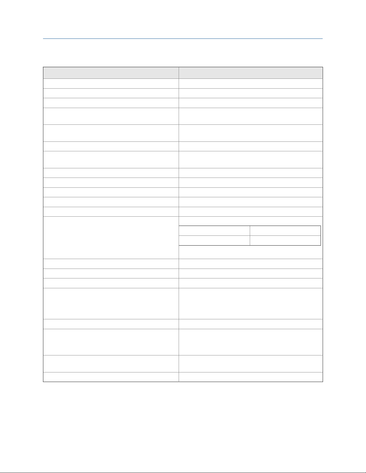
Other specificationsTable 1-2:
Maximum tempera-
Type PN Wetted materials Process connection
Low
flow
cell
(1) Temperature and pressure specifications for the low flow cell exceed the temperature and pressure specifications for the sensor.
24091-00 Polycarbonate/poly-
ester, 316 stainless
(1)
steel, and silicone
Compression fitting
for 1/4 in. O.D. tubing
or 1/4 in. FNPT
ture Maximum pressure
158 °F (70 °C) 90 psig (722 kPa abs)
Plan
Quick Start Guide 3
Page 8

Plan
4 Rosemount 499ATrDO
Page 9
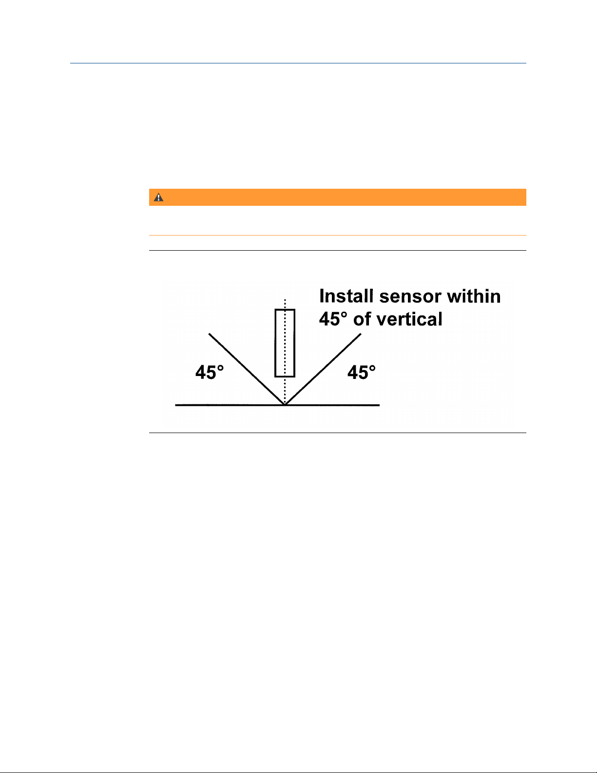
2 Install
The gray PVC cap contains a solution of sodium sulfite. Remove the cap before installing
the sensor.
WARNING!
POISONOUS SUBSTANCE
The cap contains sodium sulfite solution. Avoid contact with skin or eyes. Do not swallow!
Install
Sensor OrientationFigure 2-1:
Quick Start Guide 5
Page 10

Install
Low Flow Cell (PN 24091-00)Figure 2-2:
6 Rosemount 499ATrDO
Page 11

3 Wire
NOTICE
For additional wiring information on this product, including sensor combinations not shown
here, please refer to the Liquid Transmitter Wiring Diagrams.
Wire
Figure 3-1:
Rosemount 499ATrDO-54 Sensor Wiring to Rosemount 1056 and 56
Transmitters
Quick Start Guide 7
Page 12

Wire
Figure 3-2:
Rosemount 499ATrDO-54-60 and 499ATrDO-54-VP Sensor Wiring to
Rosemount 1056 and 56 Transmitters
8 Rosemount 499ATrDO
Page 13

Wire
Rosemount 499ATrDO-54 Sensor Wiring to Rosemount 5081 transmitterFigure 3-3:
Quick Start Guide 9
Page 14

Wire
Figure 3-4:
Rosemount 499ATrDO-54-60 and 499ATrDO-54-VP Sensor Wiring to
Rosemount 5081 Transmitter
10 Rosemount 499ATrDO
Page 15

Wire
Rosemount 499ATrDO-54 Sensor Wiring to Rosemount 1066 TransmitterFigure 3-5:
Quick Start Guide 11
Page 16

Wire
Figure 3-6:
Rosemount 499ATrDO-54-60 and 499ATrDO-54-VP Sensor Wiring to
Rosemount 1066 Transmitter
Figure 3-7:
Rosemount 499ATrDO Sensor Pin-out Diagram (Top View of Connector
End of Sensor)
12 Rosemount 499ATrDO
Page 17

When making a connection through a junction box (PN 23550-00), wire point-to-point.
NOTICE
Use a wire nut and pigtail (included) when connecting several wires to the same terminal.
Wire
Quick Start Guide 13
Page 18

Wire
14 Rosemount 499ATrDO
Page 19

4 Calibrate
4.1 Zero point calibration
Even in the absence of oxygen, the Rosemount 499ATrDO sensor generates a small signal
called the zero current. Normally, the zero current is less than 5 nA, which introduces nor
more than a 0.5 ppb error in measurement. Zero the sensor when it is first placed in service
and every time the fill solution is changed.
To zero the sensor:
Procedure
1. Pour a cup of deionized or bottled water.
2. Add a teaspoon of sodium sulfite to the water.
3. Place the sensor in the water.
4. Wait until the sensor current has reached a stable low value (at least two hours).
5. Measure the current.
Calibrate
a. If it is less than 5 nA, do not zero the sensor.
b. If it is between 5 and 10 nA, allow the sensor to run overnight. Zero the sensor if
the reading is still between 5 and 10 nA and is stable.
c. If it is greater than 10 nA, call the factory.
4.2 Full scale
The Rosemount 499ATrDO sensor is best calibrated by exposing the sensor to watersaturated air.
1. Pour a small amount of water into a cup.
2. Suspend the sensor, keeping the membrane dry, about 1/4 in. (6 mm) above the
surface of the water.
3. Once readings are stable, which should take no longer than 20 minutes, follow the
analyzer prompts to complete the calibration.
The analyzer automatically calculates the equilibrium solubility of atmospheric
oxygen in water under the prevailing temperature and barometric pressure.
4. After calibration, go to the Diagnostics menu and check the sensitivity.
The sensitivity should be between 3,600 and 6,100 nA/ppm.
For more information, refer to the transmitter manual.
Quick Start Guide 15
Page 20

Calibrate
Prolonged exposure to air may affect the linearity of the sensor. If the cumulative
exposure to air is less than about five hours per year, sensor linearity should be
within specification. If cumulative exposure exceeds five hours per year, restore
linear response of the sensor by draining the electrolyte solution and replacing it
with fresh.
16 Rosemount 499ATrDO
Page 21

5 Maintenance
Periodic maintenance and cleaning are required for best performance of the sensor.
Generally, the membrane and fill solution should be replaced every four to six months. The
optimum maintenance frequency is best determined by experience. Periodically check the
zero current and sensitivity. If the zero current is less than about 5 nA, and the current in
the air is between 30 and 45 nA with a variability of less than 2%, the sensor does not need
maintenance.
WARNING!
PRESSURIZED SPRAY INJURY
Before removing the sensor, be absolutely certain that the process pressure is reduced to
0 psig and the process temperature is lowered to a safe level!
5.1 Cleaning the membrane
Maintenance
Keep the membrane clean and free from solid corrosion products. Clean the membrane
with water sprayed from a wash bottle or gently wipe the sensor with a soft, clean tissue.
5.2 Replacing the electrolyte solution and membrane
WARNING!
HARMFUL SUBSTANCE
Fill solution may cause irritation. May be harmful if swallowed. Read and follow manual.
Procedure
1. Unscrew the membrane retainer.
2. Remove the membrane assembly and O-ring.
See Figure 1-1.
3. Hold the sensor over a container with the cathode pointing down.
4. Remove the fill plug.
5. Allow the electrolyte solution to drain out.
6. Inspect the cathode.
a. If it is tarnished, clean it by gently rubbing in the direction of the existing
scratches (do not use a circular motion) with 400-600 grit silicon carbide
finishing paper.
Quick Start Guide 17
Page 22

Maintenance
7. Remove the old pipe tape from the plug.
8. Wrap the plug with one or two turns of pipe tape.
9. Prepare a new membrane.
a. Hold the membrane assembly with the cup formed by the membrane and
membrane holder pointing up.
b. Place a drop of isopropyl alcohol in the cup.
c. Slowly add about 20 drops of electrolyte solution to the cup.
This step is important, because alcohol wets the inside surface of the membrane
and ensures that no air bubbles will be trapped when the membrane assembly is
placed over the cathode.
d. Fill the cup with electrolyte solution.
e. Leave the membrane assembly filled with electrolyte solution and set it aside.
10. Hold the sensor at about a 45° angle with the cathode end pointing up.
11. Add electrolyte solution through the fill hole until the liquid overflows.
12. Tap the sensor near the threads to release trapped air bubbles.
13. Add more electrolyte solution if necessary.
14. Place the fill plug in the electrolyte port and begin screwing it in.
15. After several threads have engaged, rotate the sensor so that the cathode is
pointing up and continue tightening the fill plug.
Do not overtighten.
16. Place a new O-ring in the groove around the cathode post.
17. Cover the holes at the base of the cathode stem with several drops of electrolyte
solution.
18. Insert a small blunt probe, like a toothpick with the end cut off, through the pressure
equalizing port.
See Figure 1-1.
CAUTION!
EQUIPMENT DAMAGE
Do not use a sharp probe. It will puncture the bladder and destroy the sensor.
19. Gently press the probe against the bladder several times to force liquid through the
holes at the base of the cathode stem. Keep pressing the bladder until no air bubbles
can be seen leaving the holes. Be sure the holes remain covered with electrolyte
solution.
20. Place a drop of electrolyte solution on the cathode; then place the membrane
assembly over the cathode.
21. Screw the membrane retainer in place.
The sensor may require several hours operating at the polarizing voltage to
equilibrate after the electrolyte solution has been replenished.
18 Rosemount 499ATrDO
Page 23

5.3 Storage
Store the sensor with the membrane immersed in a fresh solution of saturated sodium
sulfite. You can use the PVC cap shipped with the sensor. Leave the power to the
transmitter turned on.
Maintenance
Quick Start Guide 19
Page 24

Maintenance
20 Rosemount 499ATrDO
Page 25

6 Accessories
Part number Description
23747-06 Interconnecting cable, VP 6, 2.5 ft (0.8 m)
23747-04 Interconnecting cable, VP 6, 4 ft (1.2 m)
23747-02 Interconnecting cable, VP 6, 10 ft (3.0 m)
23747-07 Interconnecting cable, VP 6, 15 ft (4.6 m)
23747-08 Interconnecting cable, VP 6, 20 ft (6.1 m)
23747-09 Interconnecting cable, VP 6, 25 ft (7.6 m)
23747-10 Interconnecting cable, VP 6, 30 ft (9.1 m)
23747-03 Interconnecting cable, VP 6, 50 ft (15.2 m)
23747-11 Interconnecting cable, VP 6, 100 ft (30.5 m)
24091-00 Low flow cell with 1/4 in. OD tubing compression fittings
9390004 Rotameter: 0.5 - 5.0 gph
22550-00 Junction box, 12 terminals
9200266 Extension cable, standard, unprepped
9200275 Extension cable for optimum EMI/RFI cable, unprepped
23747-00 Extension cable for optimum EMI/RFI cable, prepped
23501-04 Trace dissolved oxygen membrane kit: includes 1 membrane assembly and 1
O-ring
25302-04 Trace dissolved oxygen membrane kit: includes 3 membrane assemblies and
3 O-rings
9210264 Dissolved oxygen sensor fill solution, 4 oz (125 mL)
33521-02 Membrane retainer
33523-03 Electrolyte fill plug
9390094 O-ring, Viton 2-014
Accessories
Quick Start Guide 21
Page 26

Accessories
22 Rosemount 499ATrDO
Page 27

Accessories
Quick Start Guide 23
Page 28

www.Emerson.com/RosemountLiquidAnalysis
Emerson Automation Solutions
8200 Market Blvd
Chanhassen, MN 55317
Toll Free +1 800 999 9307
F +1 952 949 7001
liquid.csc@emerson.com
www.Emerson.com/RosemountLiquidAnalysis
EUROPE
Emerson Automation Solutions
Neuhofstrasse 19a P.O. Box 1046
CH-6340 Baar
Switzerland
T + 41 (0) 41 768 6111
F + 41 (0) 41 768 6300
liquid.csc@emerson.com
www.Emerson.com/RosemountLiquidAnalysis
LIQ-QSG-499ATrDO
Rev H
2017
MIDDLE EAST AND AFRICA
Emerson Automation Solutions
Emerson FZE
Jebel Ali Free Zone
Dubai, United Arab Emirates, P.O. Box 17033
T +971 4 811 8100
F +971 4 886 5465
liquid.csc@emerson.com
www.Emerson.com/RosemountLiquidAnalysis
ASIA-PACIFIC
Emerson Automation Solutions
1 Pandan Crescent
Singapore 128461
Singapore
T +65 777 8211
F +65 777 0947
liquid.csc@emerson.com
www.Emerson.com/RosemountLiquidAnalysis
©
2017 Emerson Automation Solutions. All rights reserved.
The Emerson logo is a trademark and service mark of Emerson
Electric Co. Rosemount is a mark of one of the Emerson family of
companies. All other marks are the property of their respective
owners. The contents of this publication are presented for
information purposes only, and while effort has been made to
ensure their accuracy, they are not to be construed as warranties or
guarantees, expressed or implied, regarding the products or
services described herein or their use or applicability. All sales are
governed by our terms and conditions, which are available on
request. We reserve the right to modify or improve the designs or
specifications of our products at any time without notice.
 Loading...