

Page 1
WARNING
Before removing the sensor, be absolutely certain
that the process pressure is reduced to 0 psig and
the process temperature is lowered to a safe level!
Model 404
ENDURANCE™Conductivity Sensor
Instruction Sheet
PN 51A-404/rev.M
December 2010
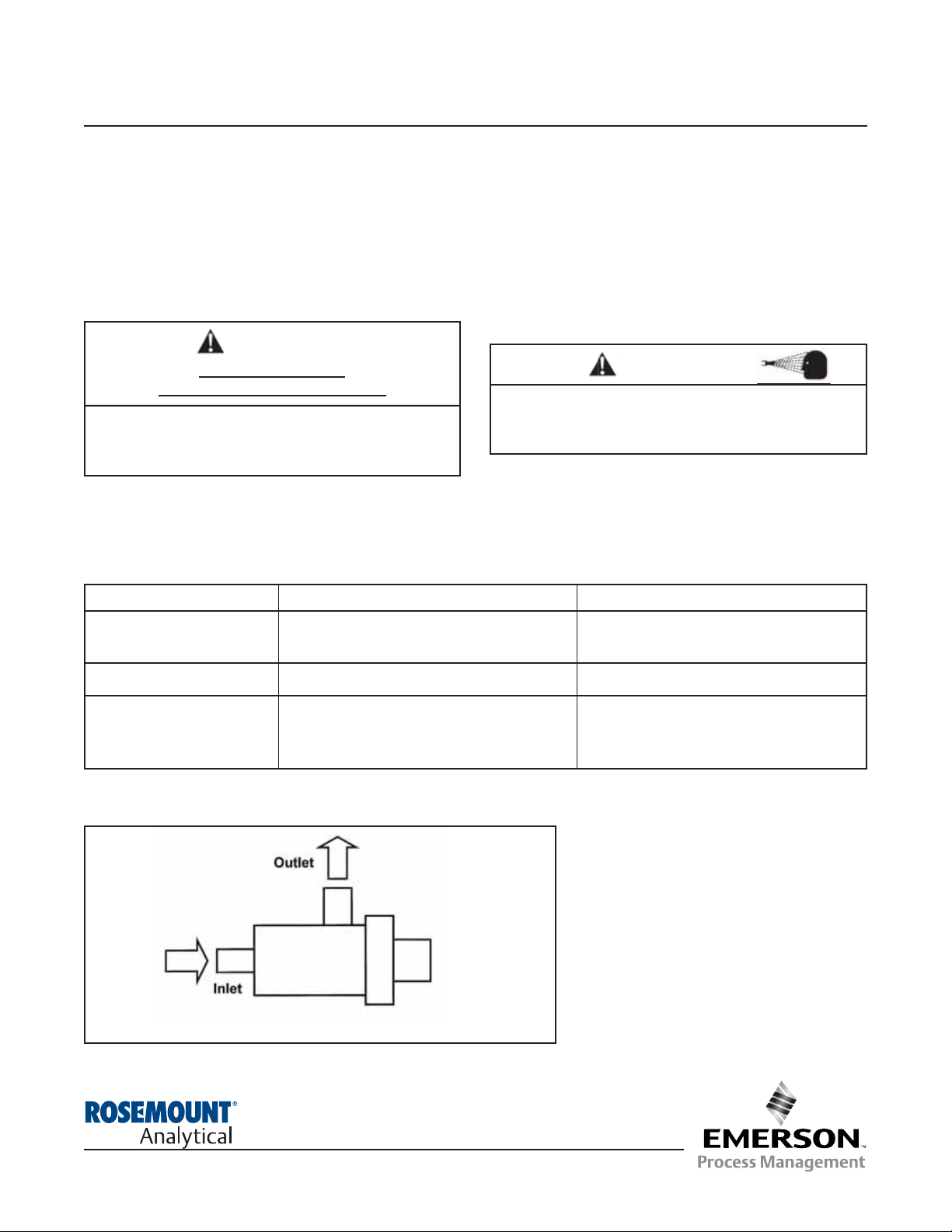
If the sensor is installed in a sidestream
with the sample draining to open atmosphere, bubbles may accumulate on the
electrodes. Trapped bubbles will cause
errors. Normally, as bubbles accumulate the conductivity reading drifts down.
To control bubble formation, apply a small
amount of back pressure to the sensor.
SENSOR SPECIFICATIONS
SPECIFICATIONS
MODEL 404-16 (PVC body) MODEL 404-17 (stainless steel body)
Wetted Materials Titanium, PEEK (glass filled), PVC, Titanium, PEEK (glass filled),
EPDM, polyethylene 303 SST, EPDM
Temperature Range 32-140°F (0-60°C) 32-212°F (0-100°C)
Maximum Pressure 20 psig (239 kPa abs) at 60°C (140°F) 100 psig (791 kPa abs)
100 psig (791 kPa abs) at 25°C (77°F)
(use FNPT fittings only)
FIGURE 1. Installation of Model 404 Sensor
For additional information, please visit our website
at www.emersonprocess.com/raihome/liquid/.
INSTALLATION
The wetted sensor materials may not be compatible
with process com position and operating conditions.
Application compat ibility is entirely the
responsi-
bility of the user.
CAUTION
SENSOR/PROCESS
APPLICATION COMPATIBILITY
WARNING
Page 2
2
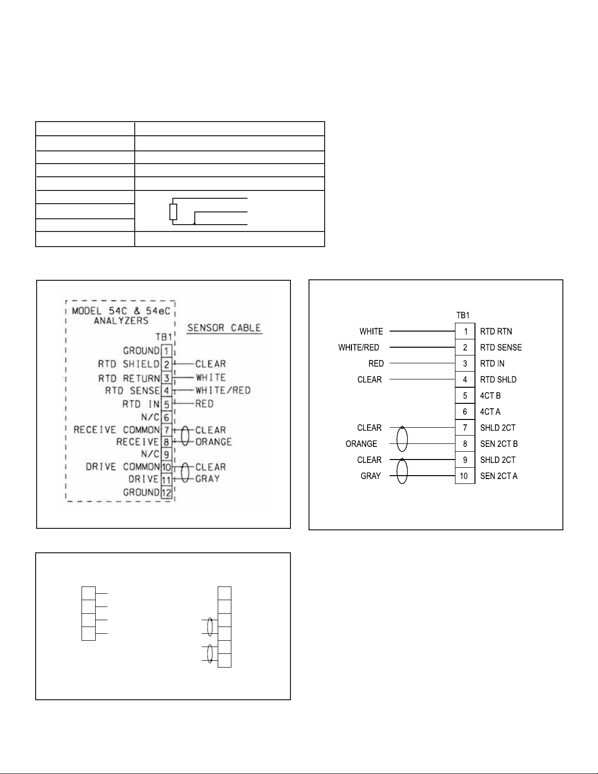
MODEL 404 WIRING
WIRING DIAGRAMS
FIGURE 2. Model 54eC Wiring
FIGURE 3. Model 56 and 1056 Wiring
WIRING
WIRE COLOR AND CONNECTIONS IN SENSOR
COLOR FUNCTION
Gray Connects to outer electrode
Clear Coaxial shield for gray wire
Orange Connects to inner electrode
Clear Coaxial shield for orange wire
Red
White with red stripe
White
Clear Shield for all RTD lead wires
RTD
RTD in
RTD sense
RTD return
RCV B
RCV A
RSHLD
DRVB
RTN
SENSE
RTD IN
SHLD
CLEAR
WHITE/RED
RED
DRVA
DSHLD
WHITE
CLEAR
GRAY
ORANGE
CLEAR
TB1TB2
FIGURE 4. Model 1066 Wiring
Page 3
3
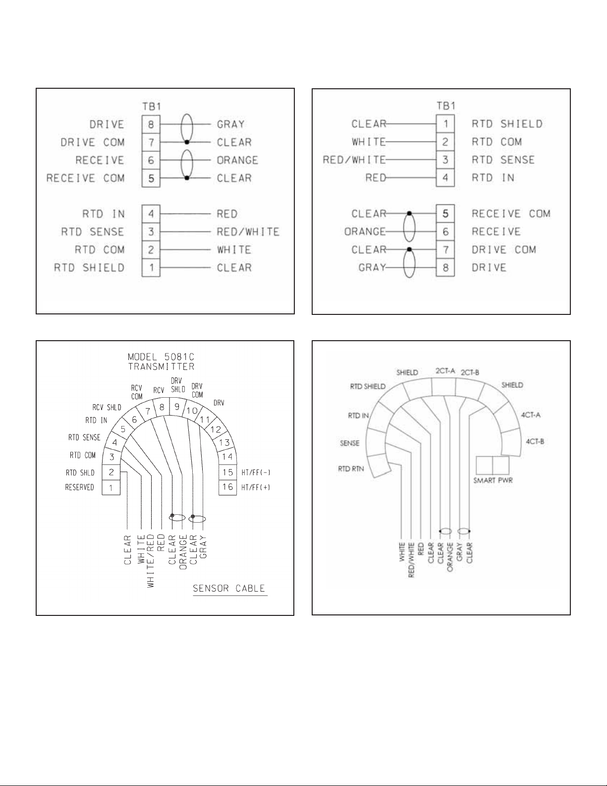
MODEL 404 INSTALLATION
FIGURE 5. Model Xmt-C-10 Wiring (Panel)
FIGURE 6. Model Xmt-C-11 Wiring (Pipe or Wall)
FIGURE 7. Model 5081-C Wiring
FIGURE 8. Model 6081-C Wiring
WIRING THROUGH A JUNCTION BOX
If wiring connections are made through a remote junction box (PN 23550-00), wire point-to-point. Use cable 23747-00
(factory-terminated) or 9200275 (no terminations).
Page 4

4
MODEL 404 WIRING
CLEANING THE SENSOR
The 404-17 (stainless steel body) sensor can be taken apart for cleaning. However, in some cases, disassembling and
reassembling the sensor can cause the cell constant to change as much as 1%. For maximum accuracy, the cell constant should be rechecked after the sensor has been reassembled. The 400-16 (PVC body) sensor cannot be taken
apart.
Use a warm detergent solution and a soft brush or pipe cleaner to remove oil and scale. Isopropyl alcohol (rubbing alcohol) can also be used to remove oily films. Avoid using strong mineral acids to clean conductivity sensors.
CALIBRATION
ENDURANCE conductivity sensors are calibrated at the factory and do not need calibration when first placed in service.
Simply enter the cell constant printed on the label into the analyzer.
After a period of service, the sensor may require calibration. Because Model 404 sensors have a flow-through design,
they are best calibrated against a referee meter and sensor where the two sensors are connected in series with the
same liquid flowing through both.
For more information about calibrating contacting conductivity sensors, refer to application sheet ADS 43-024, available
on the Rosemount Analytical website.
Page 5

5
MODEL 404 WIRING
TROUBLESHOOTING
PROBLEM PROBABLE CAUSE SOLUTION
Off-scale reading Wiring is wrong. Verify wiring.
Temperature element is open or shorted. Check temperature element for open or
short circuits. See Figure 9.
Sensor is not in process stream. Be sure sensor is completely submerged in
process stream.
Variopol cable is not properly seated. Loosen connector and reseat.
Sensor has failed. Perform isolation checks. See Figure 10.
Noisy reading Sensor is improperly installed in process Be sure sensor is completely submerged
stream. in process stream.
Variopol cable is not properly seated. Loosen connector and reseat.
Reading seems wrong (lower Bubbles trapped in sensor. Be sure sensor is properly oriented in
or higher than expected) pipe or flow cell. See Figure 1.
Apply back pressure to flow cell.
Wrong temperature correction algorithm. Check that temperature correction is
appropriate for the sample. See analyzer
manual for more information.
Wrong cell constant. Verify that the correct cell constant has
been entered in the analyzer and that the
cell constant is appropriate for the conductivity
of the sample. See analyzer manual.
Sluggish response Electrodes are fouled. Clean electrodes.
Sensor is sampling a dead area. Move sample line to a location more
representative of the process liquid.
FIGURE 9. Checking Temperature Element
Disconnect leads and measure resistance shown. The measured resistance should be close to the value in the table.
FIGURE 10. Checking Continuity and Leakage
Disconnect electrode leads and measure resistance and
continuity as shown. Sensor must be dry when checking
resistance between electrode leads.
Page 6

6
NOTES
Page 7

7
NOTES
Page 8

Credit Cards for U.S. Purchases Only.
The right people,
the right answers,
right now.
ON-LINE ORDERING NOW AVAILABLE ON OUR WEB SITE
http://www.raihome.com
Specifications subject to change without notice.
Emerson Process Management
2400 Barranca Parkway
Irvine, CA 92606 USA
Tel: (949) 757-8500
Fax: (949) 474-7250
http://www.raihome.com
© Rosemount Analytical Inc. 2010
8
 Loading...