

Page 1
Instruction Manual
IQ-MAN-396-396VP-397-398-398VP
L
Rev. M
March 2017
Rosemount
pH/ORP Sensors
™
396/396VP/397/398/398VP
Page 2

asgkas
h
Page 3

Essential Instructions
Read this page before proceeding!
Emerson designs, manufactures and tests its products to meet many national and international stan-
dards. Because these sensors are sophisticated technical products, you MUST properly install, use,
nd maintain them to ensure they continue to operate within their normal specifications. The
a
following instructions MUST be adhered to and integrated into your safety program when installing,
using, and maintaining Rosemount products. Failure to follow the proper instructions may cause
any one of the following situations to occur: loss of life; personal injury; property damage; damage
to this sensor; and warranty invalidation.
• Read all instructions prior to installing, operating, and servicing the product.
• If you do not understand any of the instructions, contact your Emerson representative for
clarification.
• Follow all warnings, cautions, and instructions marked on and supplied with the product.
• Inform and educate your personnel in the proper installation, operation, and maintenance
of the product.
• Install your equipment as specified in the Installation Instructions of the appropriate
Instruction Manual and per applicable local and national codes. Connect all products to
the proper electrical and pressure sources.
• To ensure proper performance, use qualified personnel to install, operate, update,
program, and maintain the product.
• When replacement parts are required, ensure that qualified people use replacement parts
specified by Emerson. Unauthorized parts and procedures can affect the product's
performance, place the safe operation of your process at risk, and VOID YOUR WARRANTY.
Third-party substitutions may result in fire, electrical hazards, or improper operation.
• Ensure that all equipment doors are closed and protective covers are in place, except when
maintenance is being performed by qualified persons, to prevent electrical shock and
personal injury.
The information contained in this document is subject to change without notice.
DANGER
Hazardous Area InstallationN
This sensor is not Intrinsically Safe. or Explosion Proof. Installations near flammable liquids or in
hazardous area locations must be carefully evaluated by qualified on site safety personnel.
To secure and maintain an intrinsically safe installation, an appropriate transmitter/safety
barrier/sensor combi nation must be used. The installation system must be in accordance with the
governing approval agency (FM, CSA or BASEEFA/CENELEC) hazardous area classification requirements. Consult your transmitter instruc tion manual for details.
Proper installation, operation and servicing of this sensor in a Hazardous Area Instal lation is entirely
the responsibility of the user.
CAUTION
Sensor/Process Application Compatibility
The wetted sensor materials may not be compatible with process composition and operating
conditions. Application compatibility is entirely the responsibility of the user.
Page 4

About This Document
This manual contains instructions for installation and operation of the Rosemount 396, 396VP, 397,
398, and 398VP pH/ORP Sensors.
The following list provides concerning all revisions of this document.
Rev. Level Date Notes
0 03/99 This is the initial release of the product manual. The manual has been
reformatted to reflect the Emerson documentation style and updated
to reflect any changes in the product offering.
A 12/01 Revised wiring diagram on page 24.
B 2/02 Added info to page 1.
C 6/02 Updated multiple drawings.
D 8/02 Added drawing #40105549, rev. D.
E 10/02 Revised drawing #40039601, rev. J, on page 10.
F 4/03 Revised Model 397 specs on page 2, and revised drawing on page 27.
G 8/03 Added Silcore information.
H 3/04 Added Xmt wiring drawings.
I 10/04 Added 5081 wiring drawing and updated 1055 wiring.
J 2/06 Changed drawing 40039603 rev. C, on page 13. Added a note on
page 15.
K 1/07 Miscellaneous revisions.
L 11/10 Removed mention of patents and updated dnv logo.
M 03/17 Updated Ordering Information, Wiring Diagrams, Accessories, Emerson
Logo and Address. Also, added FM Installation drawing and EC
Declaration of Conformity
Page 5

Instruction Manual Table of Contents
LIQ-MAN-396-396VP-397-398-398VP March 2017
Contents
Section 1: Description and Specifications
1.1 TUpH Features and Applications ..........................................................................1
1.2 Specifications ......................................................................................................3
1.3 Product Certifications ..........................................................................................4
1.4 Ordering Information...........................................................................................6
Section 2: Installation
2.1 First Time Installation ..........................................................................................9
2.2 Unpacking and Inspection .................................................................................10
2.3 Mounting...........................................................................................................10
2.4 Electrical Installation..........................................................................................17
Section 3: Startup and Calibration
3.1 Sensor Preparation ............................................................................................33
3.2 Calibration Using Buffer Solution or Grab Sample...............................................33
Section 4: Maintenance
4.1 Electrode Cleaning.............................................................................................35
4.2 Automatic Temperature Compensator...............................................................36
Section 5: Troubleshooting..................................................................................37
Section 6: Accessories
6.1 Accessories........................................................................................................39
EC Declaration of Conformity.............................................................................41
Intrisicallly Safe Sensor Installation Drawing - FM ................................43
Table of Contents i
Page 6

Table of Contents Instruction Manual
March 2017 LIQ-MAN-396-396VP-397-398-398VP
ii Table of Contents
Page 7
Instruction Manual Description and Specifications
LIQ-MAN-396-396VP-397-398-398VP March 2017
Section 1: Description and Specifications
1.1 TUpH Features and Applications
The low maintenance and disposable Rosemount 396, 396VP, 397, 398, and 398VP TUpH sensors
offer long life and high performance in measuring pH or ORP in aqueous solutions in pipelines, open
tanks, or ponds.
These TUpH sensors feature a large area reference junction for maximum resistance to process
coatings, generally found in dirty, high solid applications. In addition, the secondary helical reference
pathway serves as added protection from poisoning ions. The simplified construction, designed
with user convenience in mind, does not require electrolyte replenishment or any component
replacement. All models feature a large glass bulb for increased resistance to the effects of aging for
longer life.
1.1.1 Rosemount 396 and 396VP Sensor Features and Applications
Rosemount 396/396VP sensors are constructed of
polypropylene and stainless steel and are completely
sealed by EP (ethylene propylene) to eliminate process
intrusion.
Sesnors are specially designed for improved life in harsh,
dirty applications such as lime slurry waste treatment
and paper machine headbox and pigment/dye
applications where large quantities of suspended solids
are present. Installation is easily achieved through a wide
variety of mounting configurations.
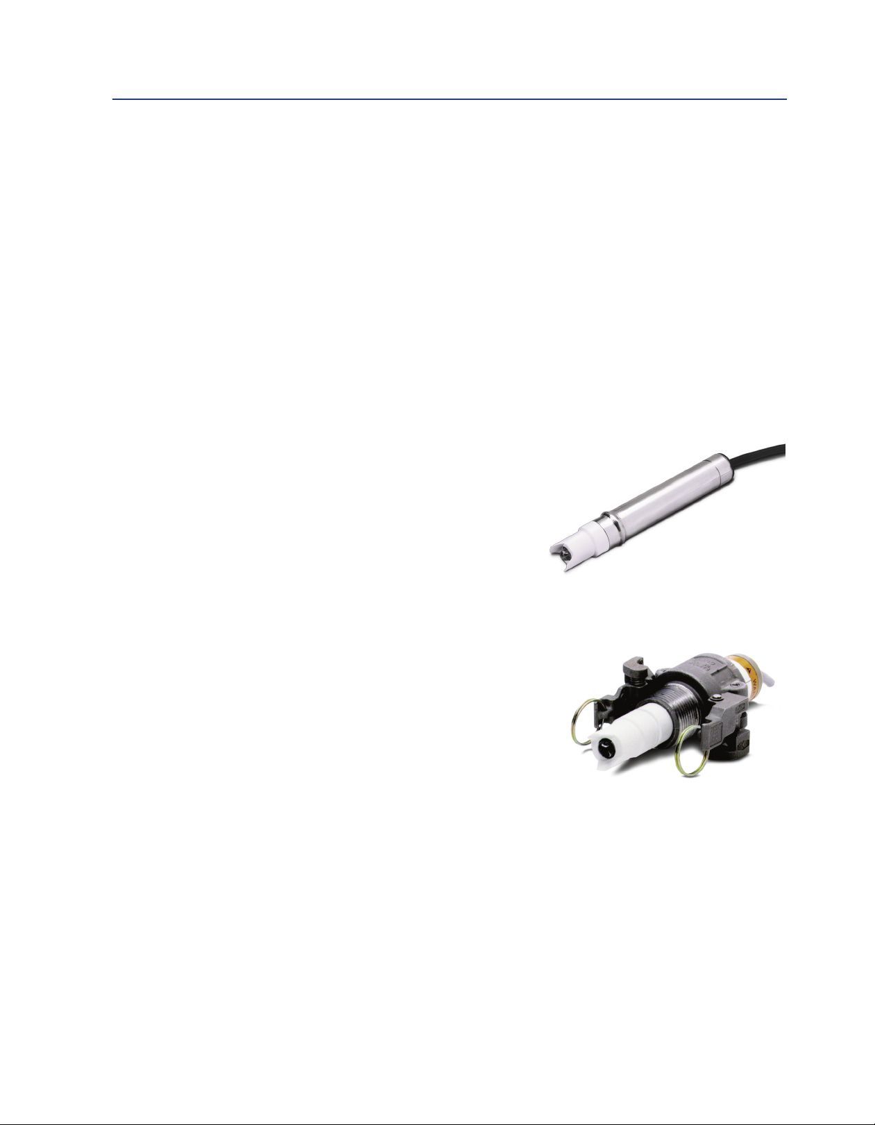
1.1.2 Rosemount 397 Sensor Features and Applications
The Rosemount 397 is housed in a highly chemical resistant
polypropylene body and completely sealed with EP to
eliminate process intrusion. The Rosemount 397 body is
specifically designed for use with the Quik-Loc Kit which
consists of an adapter and coupler. The PEEK (poly
etheretherke tone) adapter enables the Rosemount 397
sensor to fit into a 1 in. MNPT Dixon coupler for quick and
easy removal without sensor cable twisting. The 316 stain
less steel DIxon coupler is sealed with EP an features locking
arms. The Quik-Loc Kit is not recommended for use in
processes with hazardous, corrosive, or strong oxidizing
chemicals due to a risk of spray and bodily hazards.
1.1.2 Rosemount 398 and 398VP Sensor Features and Applications
The chemical-resistant construction of Tefzel, titanium, and the TUpH reference junction make the
Rosemount 398 and 398VP the ideal sensors for measuring pH in harsh process liquids. Use these
sensors to measure pH in sour water strippers, in pulp bleaching towers that use chlorine dioxide,
and in process streams containing a variety of organic solvents.
Rosemount 398 and 398VP sensors use the highest quality materials to provide superior chemical
resistance. The sensors are housed in a titanium tube and features an optional 1 inch MNPT process
connector for insertion, submersion, or flow-through applications. The molded Tefzel TUpH
construction is offered with a choice of seals (Viton, EPDM, or Kalrez).
Description and Specifications 1
Page 8
Description and Specifications Instruction Manual
March 2017 LIQ-MAN-396-396VP-397-398-398VP
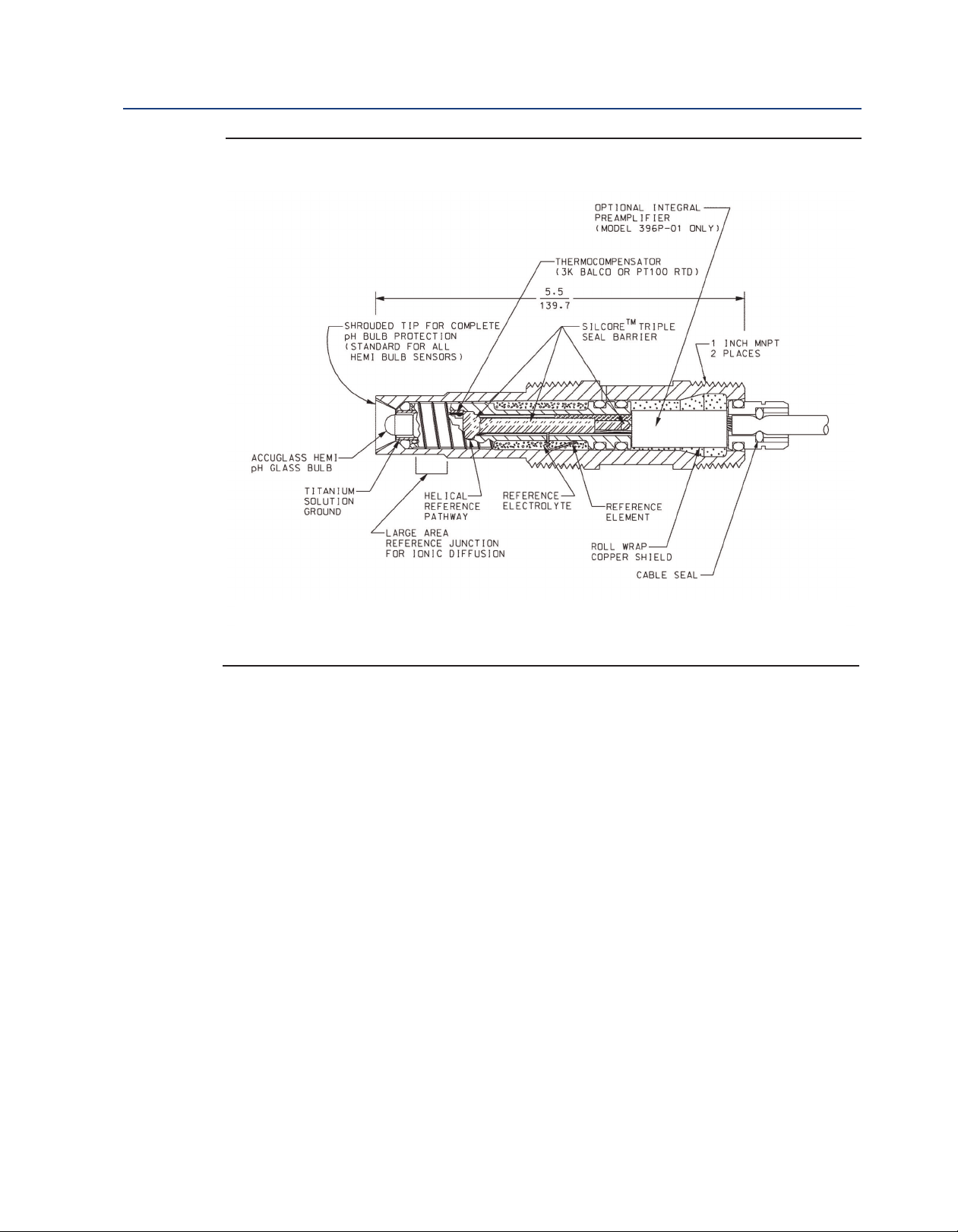
Figure 1-1: Cross Section Diagram of the TUpH Reference Technology
All TUpH sensors are designed with a large area reference junction, helical reference pathway, and an
AccuGlass pH glass bulb. This sensor technology ensures superior performance while only requiring
minimal maintenance.
2 Description and Specifications
Page 9

Instruction Manual Description and Specifications
LIQ-MAN-396-396VP-397-398-398VP March 2017
1.2 Specifications
Table 1-1: Percent linearity over pH
396, 396VP, 397, 398, 398VP 396, 396VP, 397, 398, 398VP
pH Range GPHT Hemi GPLR Hemi
0-2 pH 94% 93%
-12 pH
2
12-13 pH 97% 95%
13-14 pH 92% --
Table 1-2: Rosemount 396, 396VP, 397, 398 and 398VP Specifications
Rosemount 396
396VP
Measured Ranges 0 to 14 pH 0 to 14 pH
ORP: -1500 mV to 1500 mV
Available pH
ACCUGLASS Types
GPHT hemi bulb or
GPLR flat bulb
9%
9
Rosemount 398
398VP
GPHT hemi bulb or
GPLR flat bulb GPHT hemi bulb
Rosemount 397 Quik-loc Kit
0 to 14 pH
8%
9
_
_
316 SST,
Wetted Materials
Process Connection
Temperature Range 0-100 °C (32-212 °F) 0-100 °C (32-212 °F) 0-100 °C (32-212 °F)
Pressure Range-
Hemi bulb
Pressure Range-
Flat bulb
Minimum
Conductivity
Preamplifier Options Remote Remote Remote
Weight/Shipping
Weight
Polypropylene, EPDM, glass
None, use 1 in. NPT
process connector,
PN 23166-00 or 23166-01
(sold separately)
100-1136 kPa abs
(0-150 psig)
100-790 kPa abs
(0-100 psig)
75 µS/cm, nominal 75 µS/cm, nominal 75 µS/cm, nominal
0.45 kg/0.9 kg (1 lb/2 lb) 0.45 kg/0.9 kg (1 lb/2 lb) 0.45 kg/0.9 kg (1 lb/2 lb) 0.45 kg/0.9 kg
Titanium, Tefzel, glass,
choice of Kalrez, Viton, or
EPDM (platinum: ORP only)
None, use 1 in. NPT
process connector,
PN 23166-00 or 23166-01
(sold separately)
100-1825 kPa abs
(0-250 psig)
100-790 kPa abs
(0-100 psig)
Polypropylene, EP, glass 316 SST, EP, PEEK
None, must use Quik-Loc
kit which includes 1 in.
MNPT process
connection
100-790 kPa abs
(0-100 psig)
_ _
1-in. MNPT
_
(1 lb/2 lb)
Description and Specifications 3
Page 10

Description and Specifications Instruction Manual
March 2017 LIQ-MAN-396-396VP-397-398-398VP
1.3 Product Certifications
Please see online certificates for further details.
osemount 396/396VP:
R
IECEx
Sensors without preamp (pH and ORP) – Ex ia IIC T4 Ga (-20 °C ≤ Ta ≤ +60 °C)
Sensors with SMART preamp (pH only) – Ex ia IIC T4 Ga (-20 °C ≤ Ta ≤ +60 °C)
Sensors with standard preamp (396P only) – Ex ia IIC T4 Ga (-20 °C ≤ Ta ≤ +80 °C) or
Ex ia IIC T5 Ga (-20 °C ≤ Ta ≤ +40 °C)
Per standards IEC60079-0 : 2011, IEC 60079-11 : 2011
ATEX
Sensors without preamp (pH and ORP) – II 1 G Ex ia IIC T4 Ga (-20 °C ≤ Ta ≤ +60 °C)
Sensors with SMART preamp (pH only) – II 1 G Ex ia IIC T4 Ga (-20 °C ≤ Ta ≤ +60 °C)
Sensors with standard preamp (396P only) – II 1 G Ex ia IIC T4 Ga (-20 °C ≤ Ta ≤ +80 °C) or
II 1 G Ex ia IIC T5 Ga (-20 °C ≤ Ta ≤ +40 °C)
Per standards EN 60079-0: 2012+A11:2013, EN 60079-11:2012
FM
See online FM Certificate of Compliance for applicable sensor options:
Intrinsically Safe for use in Class I, II, and III, Division 1, Groups A, B, C, D, E, F, and G; Temperature
Class T6 Ta = -20 °C to +60 °C
Intrinsically Safe for use in Class I, Zone 0, AEx ia IIC T6 Ta = -20 °C to +60 °C
Nonincendive for use in Class I, Division 2, Groups A, B, C, and D; Temperature Class T6 Ta = -20 °C
to +60 °C
Suitable for use in Class II and III, Division 2, Groups E, F, and G; Temperature Class T6 Ta = -20 °C
to +60 °C Hazardous (Classified) Locations
IS/I,II,III/1/ABCDEFG/T6 Ta = 60 °C - 1400332; Entity; I/0/AEx ia IIC/T6 Ta = 60 °C - 1400332; Entity;
NI/I/2/ABCD/T6 Ta = 60 °C; S/II,III/2/EFG/T6 Ta = 60 °C
Per standards 3600:1998, 3610:2010, 3611:2004, 3810:2005
CSA
See online CSA Certificate of Compliance for applicable sensor options:
Sensors with preamp – Intrinsically Safe:
Class I, Division 1, Groups ABCD; Class II, Division 1, Groups EFG; Class III; Class I, Division 2, Groups
ABCD; Ambient temperature rating -20 °C to +60 °C; Ex ia IIC; T6
Sensors without preamp – Intrinsically Safe and Non-Incendive:
Class I, Division 1, Groups ABCD; Class II, Division 1, Groups EFG; Class III; Class I, Division 2, Groups
ABCD; Ex ia IIC; T6; Ambient temperature rating -20 °C to +60 °C: (Simple Apparatus)
Per standards C22.2 No. 0-10, C22.2 No. 0.4-M2004, C22.2 No. 94-M1991, C22.2 No. 142 – M1987,
C22.2 No 157 – M1992, CAN/CSA E60079-0:07, CAN/CSA E60079- 11:02, UL50 11th Ed, UL508
17th Ed, UL913 7th Ed,, UL 60079-0: 2005, UL 60079-11: 2002
4 Description and Specifications
Page 11

Instruction Manual Description and Specifications
LIQ-MAN-396-396VP-397-398-398VP March 2017
Rosemount 397/398/398VP:
IECEx
Ex ia IIC T4 Ga (-20 °C ≤ Ta ≤ +60 °C)
er standards IEC60079-0 : 2011, IEC 60079-11 : 2011
P
ATEX
II 1 G Ex ia IIC T4 Ga (-20 °C ≤ Ta ≤ +60 °C)
Per standards EN 60079-0: 2012+A11:2013, EN 60079-11:2012
FM
Intrinsically Safe for use in Class I, II, and III, Division 1, Groups A, B, C, D, E, F, and G; Temperature
Class T6 Ta = -20 °C to +60 °C
Intrinsically Safe for use in Class I, Zone 0, AEx ia IIC T6 Ta = -20 °C to +60˚C
Nonincendive for use in Class I, Division 2, Groups A, B, C, and D; Temperature Class T6 Ta = -20 °C
to +60 °C
Suitable for use in Class II and III, Division 2, Groups E, F, and G; Temperature Class T6 Ta = -20 °C to
+60 °C Hazardous (Classified) Locations
IS/I,II,III/1/ABCDEFG/T6 Ta = 60 °C - 1400332; Entity; I/0/AEx ia IIC/T6 Ta = 60 °C - 1400332; Entity;
NI/I/2/ABCD/T6 Ta = 60 °C; S/II,III/2/EFG/T6 Ta = 60 °C; Entity Parameters
Per standards 3600:1998, 3610:2010, 3611:2004, 3810:2005
CSA
Intrinsically Safe and Non-Incendive:
Class I, Division 1, Groups ABCD; Class II, Division 1, Groups EFG; Class III; Class I, Division 2, Groups
ABCD; Ex ia IIC; T6; Ambient temperature rating -20°C to +60°C: (Simple Apparatus)
Per standards C22.2 No. 0-10, C22.2 No. 0.4-M2004, C22.2 No. 94-M1991, C22.2 No. 142 – M1987,
C22.2 No 157 – M1992, CAN/CSA E60079-0:07, CAN/CSA E60079- 11:02, UL50 11th Ed, UL508
17th Ed, UL913 7th Ed, UL 60079-0: 2005, UL 60079-11: 2002
Description and Specifications 5
Page 12

Description and Specifications Instruction Manual
March 2017 LIQ-MAN-396-396VP-397-398-398VP
1.4 Ordering Information
The Rosemount 396 pH sensor features either a standard hemi bulb or flat glass electrode. The
sensor is housed in a stainless steel body and must be used with a 1 inch MNPT threaded process
connector (sold separately). The Rosemount 396 is not available with an integral preamplifier and
comes standard with a 15 ft integral cable.
Table 1-3: Rosemount 396 ordering information
Model Sensor type
96
3
Transmitter/TC Compatibility
50 3K TC
54 Pt-100
Cable Option
_ No Selection
62 Cable without BNC
Electrode Option
_ No Selection
71 pH - GPHT Flat Glass
Typical Model Number: 396-54-62-71
H/ORP Sensor
p
1)
(
(2)
(3)
1. For use with legacy transmitter models 1181, 1050, and 1003.
2. For wiring to Rosemount 1056, 1066, 1057, 56, and 5081 transmitters.
3. No selection will configure the sensor with a standard hemi bulb glass electrode.
The Rosemount 396VP sensor features a Variopol cable connection for use with a mating Variopol
interconnecting cable (sold separately).
Table 1-4: Rosemount 396VP ordering information
Model Sensor type
396VP pH/ORP Sensor
Temperature Compensation
50 3K TC
54 Pt-100
55 Pt-100 (for SMART Preamp)
(1)
(2)
Electrode Option
_ No Selection
71 pH - GPHT Flat Glass
(3)
Preamplifier Option
_ No Selection
70 SMART Preamplifier
Typical Model Number: 396VP-55-71-70
1. For use with legacy transmitter models 1181, 1050, 1003.
2. Must be selected with Option 70 for SMART Preamplifier.
3. No selection will configure the sensor with a standard hemi bulb glass electrode.
4. Must be selected with Option 55.
(4)
6 Description and Specifications
Page 13

Instruction Manual Description and Specifications
LIQ-MAN-396-396VP-397-398-398VP March 2017
The Rosemount 398 sensor is housed in a titanium tube and made with a Tefzel reference junction.
Sensors must be used with a 1 inch MNPT process connector (sold separately). These sensors come
with a standard 15 ft. integral cable. A preamplifier must be used if the sensor is installed more than
15 ft. from the connected transmitter.
able 1-5: Rosemount 398 ordering information
T
Model Sensor type
398 pH/ORP Sensor
Measuring Electrode Type
10 pH - GPHT Glass
12 ORP
13 pH - GPLR Flat Glass
O-ring Material
30 EPDM
31 Viton
32 Kalrez
Transmitter/TC Compatibility
1)
50 3K TC
54 Pt-100
Cable Option
_ No Selection
62 Cable without BNC
Typical Model Number: 398-10-30-54-62
(
(2)
1. For use with legacy transmitter model 1181. Not available with option 62. If selected with ORP, sensor will not come with TC.
2. For use with Rosemount transmitter models 1056, 1066, 1057, 56, and 5081. Only available with option 54.
The Rosemount 398VP sensor features a Variopol cable connection for use with a mating Variopol
interconnecting cable (sold separately).
Table 1-6: Rosemount 398VP ordering information
Model Sensor type
398VP pH/ORP Sensor
Measuring Electrode Type
10 pH - GPHT Glass
12 ORP
13 pH - GPLR Flat Glass
O-ring Material
30 EPDM
31 Viton
32 Kalrez
Transmitter/TC Compatibility
50 3K TC
54 Pt-100
Typical Model Number: 398VP-10-30-54
1. For use with legacy transmitter model 1181. If selected with ORP, sensor will not come with TC.
(1)
Description and Specifications 7
Page 14

Description and Specifications Instruction Manual
March 2017 LIQ-MAN-396-396VP-397-398-398VP
The Rosemount 397 pH sensor is housed in a polypropylene body and is designed to be used with
he Quik-Loc Kit (sold separately).
t
Table 1-7: Rosemount 397 ordering information
Model Sensor type
397 pH/ORP Sensor
Preamplifier/Cable
02 Without Integral Preamplifier, 15 ft (4.6 m) Cable
Measuring Electrode Type
10 pH - GPHT Glass
12 ORP
Transmitter/TC Compatibility
50 3K TC
54 Pt-100
Other Options
_ No Selection
62 Cable without BNC
64 Tefzel Body Material
Typical Model Number: 397-02-10-54-62
(1)
(2)
1. For use with legacy transmitter model 1181.
2. For use with Rosemount transmiter models 1056, 1066, 1057, 56, and 5081.
8 Description and Specifications
Page 15

Instruction Manual Installation
LIQ-MAN-396-396VP-397-398-398VP March 2017
Section 2: Installation
2.1 First Time Installation
For first time Rosemount 397 installations, using the following guide is recommended:
1. Quik-Loc Mounting (required for all first time installations)
Choose one: PN 23757-00, Quik-Loc Kit: for use in 1 in. tees; insertion depth 1.4 in. (35 mm)
2. Remote Junction Boxes (optional, recommended for sensor to analyzer distances of more
than 15 ft)
Choose one: PN 23555-00 includes preamplifier
3. Extension cables (used with remote junction boxes)
Choose one: PN 23646-01, 11 conductor, shielded, prepped
PN 9200273, 11 conductor, shielded, unprepped
For first time Rosemount 396/396VP/398/398VP installations, using the following guide is
recommended:
1. Process Connector Accessories (required for all first time installations with 1-inch process
connection threads)
Choose one: PN 23166-00, 316 SST, 1 in. x 1 in. NPT process connector, with EPDM O-ring
PN 23166-01, Titanium, 1 in. x 1 in. NPT process connector, with EPDM O-ring
PN 9510066, Nylon, 1 in. x 1 in. NPT process connector (submersion only)
Choose one (optional process connector o-rings)
PN 9550220, Kalrez o-ring, 2-214
PN 9550099, Viton o-ring, 2-214
2. Variopol Cable (required for all first time installations) of Models 396VP and 398VP
Choose one: PN 24281-00, 15 ft cable with mating VP connector
PN 24281-06, 10 ft cable with mating VP connector
3. Mounting Accessories (optional)
Choose one: PN 915240-03 PVC flow through tee, 3/4 in. NPT process connection
PN 915240-04 PVC flow through tee, 1 in. NPT process connection
PN 915240-05 PVC flow through tee, 1 1/2 in. NPT process connection
PN 11275-01 Sensor handrail mounting assembly
PN 2002011 1-1/2 in. CPVC Tee with 1 in. FNPT connection
PN 24091-00 Low Flow Cell
4. Remote Junction Boxes (optional, recommended for sensor to analyzer distances of more
than 15 ft)
Choose one: PN 23555-00 includes preamplifier
5. Extension cables (used with remote junction boxes)
Choose one: PN 23646-01, 11 conductor, shielded, prepped
PN 9200273, 11 conductor, shielded, unprepped
Installation 9
Page 16

Installation Instruction Manual
March 2017 LIQ-MAN-396-396VP-397-398-398VP
2.2 Unpacking and Inspection
Inspect the outside of the carton for any damage. If damage is detected, contact the carrier
immediately. Inspect the instrument and hardware. Make sure all the items in the packing list are
present and in good condition. Notify the factory if any part is missing. If the sensor appears to be
in satisfactory condition, proceed to Section 2.2, Mounting.
Note: Save the original packing cartons and materials as most carriers require proof of damage due
to mishandling, etc. Also, if it is necessary to return the instrument to the factory, you must pack the
instrument in the same manner as it was received. Refer to Section 6 for return instructions. If the
sensor is to be stored, the vinyl boot should be filled with pH buffer solution and replaced on sensor
tip until ready to use.
WARNING
Glass electrode must be wetted at all times (in storage and in line) to maximize sensor life.
2.3 Mounting
Each sensor has been designed to be located in industrial process environments. Temperature and
pressure limitations must not be exceeded at any time. A caution or warning label regarding this
matter is attached to each sensor. For insertion, transfer the label as shown on label instructions. See
Figure 2-2. For submersion applications, first note limits then remove and discard label.
Note: Before mounting the sensor, shake down the sensor to remove any air bubbles that may be
present at the tip of the pH glass bulb. In most cases, the pH sensor can simply be installed as
shipped and readings with an accuracy of ±0.6 pH may be obtained. To obtain greater accuracy or
to verify proper operation, the sensor must be calibrated as a loop with its compatible analyzer or
transmitter.
2.3.1 Flow Through and Insertion Mounting for Rosemount 396, 396VP, 398,
and 398VP Sensors.
These sensors can be used with a 1 inch MNPT process connector at the front of the sensor for
mounting into a 1-1/2 inch tee or the process. See Figure 2-1 for instal lation configurations.
2.3.2 Submersion Mounting for Rosemount 396, 396VP, 398, and 398VP
Sensors.
These sensors also have a 1 inch MNPT process connector available for use on the back of the sensor.
Tapered pipe threads in plastic fittings tend to loosen after installation. It is therefore recom mended
that Teflon tape be used on the threads and that the tightness of the connection be checked
frequently to assure that no loosening has occurred. To prevent rain water or condensation from
running into the sensor, a weatherproof junction box is recommended (see Figure 2-4). The sensor
cable must be run through a protective conduit for isolation from electrical interference or physical
abuse from the process. The sensor should be installed within 80° of vertical, with the electrode
facing down. The sensor’s cable should not be run with power or control wiring.
10 Installation
Page 17

Instruction Manual Installation
LIQ-MAN-396-396VP-397-398-398VP March 2017
2.3.2 Quik-Loc Mounting for Rosemount 397
The Quik- Loc mounting is used with the Rosemount 397 sensor only.
WARNING
Once the Quik-Loc unit is installed the operator should wait for the process to cool to a safe temperature,
use the pressure drain valve to relieve all process pressure and observe the pressure on the pressure
gauge for proper removal of the sensor without spray or bodily injury. The Quik-Loc kit used with the
Rosemount 397 sensor is not recommended for use with hazardous, corrosive, or strong oxidizing chemi
cals due to a risk of spray or bodily injury.
WARNING
It is recommended that a thermometer, drain valve to relieve pressure and pressure gauge be inserted
near the Quik-Loc assembly (see Figure 2-5).
Wrap the pipe threads of the Twin-Kam Kamloc coupler with Teflon tape before placing it into the
process pipe. The coupler can be connected to any 1 in. process connection and must be mounted
within 80° of vertical, with the electrode facing down. Once the coupler is in place, the adapter
should be positioned onto the back end of the sensor. (See Figure 2-5) Remove the parafilm wrap
ping from the two 0-rings on the sensor, grease the o-rings with the lube provided, and feed the
sensor cable through the adapter. Once the adapter is slipped over the sensor’s back end, the
retaining ring (which is included with every Rosemount 397 sensor) should be installed on the black,
grooved, back end of the sensor body. The retaining ring secures the sensor into the adapter. The
adapter/sensor assembly is now ready to be inserted into the coupler. With both arms of the coupler
in the released position, insert the adapter/sensor assembly into the coupler.
Note: The adapter can not be inserted completely or properly unless both arms are in the fully
released position (see Figure 2-5).
Once the adapter has been properly placed in the coupler, both arms should be positioned in the
locked position. A Sur- Loc™ spring arm has been provided on one arm so that the arm cannot
be opened until the spring is released.
Note: The sensor may obstruct flow through smaller pipes.
Once the arms of the coupler have been locked in position, use tamper-evident safety wire on the
metal rings of the Twin-Kam arms to prevent unauthorized and/or untrained personnel from using
the Quik-Loc unit.
WARNING
It is the responsibility of each company using the Quik-Loc Kit/ 397 TUpH Sensor to train personnel of the
injury risks associated with using a quick-release coupler that is placed in a hot or pressurized process.
The Quik-Loc unit should be used only within the pressure and temperature limits stated for the
Rosemount 397 sensor in Section 1.2.
Installation 11
Page 18

Installation Instruction Manual
March 2017 LIQ-MAN-396-396VP-397-398-398VP
Figure 2-1: Recommended Flow Through and Insertion Installation for Rosemount 396,
396VP, 398, and 398VP Sensors
1-1/2 inch Pipe Tee (PN 2002011) with 1 inch threaded connections.
Figure 2-2: Recommended Flow-Through and Insertion Installation For Rosemount 397
12 Calibration and Maintenance
Page 19

Instruction Manual Installation
LIQ-MAN-396-396VP-397-398-398VP March 2017
Figure 2-3: Dimensional Drawing For Rosemount 396 and 398 Sensors
Calibration and Maintenance 13
Page 20

Installation Instruction Manual
March 2017 LIQ-MAN-396-396VP-397-398-398VP
Figure 2-4: Rosemount 396VP and 398VP Sensor Dimensional Drawings (Shown with
Process Connector)
Metal Process Connector PN 23166-xx
(xx = 00 for 316 SST and xx = 01 for titanium)
can be used for insertion or submersion
mounting of Rosemount 396VP/398VP
sensors in 1-inch fittings.
14 Installation
The metal process connector gives the sensor
various insertions depths, depending on where
the user locates the compression fitting. Also the
threads can be switched to face the cable end of
the sensor for connection to submersion pipes.
Page 21

Instruction Manual Installation
LIQ-MAN-396-396VP-397-398-398VP March 2017
Figure 2-5: Submersion Installations for Rosemount 396, 396VP, 398, and 398VP Sensors
Installation 15
Page 22

Installation Instruction Manual
March 2017 LIQ-MAN-396-396VP-397-398-398VP
Figure 2-6: Dimensional Drawings For Rosemount 397 in the Quik-Loc Unit
16 Installation
Page 23

Instruction Manual Installation
LIQ-MAN-396-396VP-397-398-398VP March 2017
2.4 Electrical Installation
Rosemount 396, 396VP, 397, 398, and 398VP sensors are for use with a remote preamplifier. Each
ensor comes with either a special 15 ft low noise coax cable or a Variopol (VP) connector, which is
s
used with a mating Variopol cable. The cable should be handled carefully, and kept dry and free of
corrosive chemicals at all times. Extreme care should be used to prevent the cable from being
twisted, damaged or scraped by rough, sharp edges or surfaces.
For additional wiring information on this product, please refer to
Wiring Diagrams.
DANGER
DO NOT CONNECT SENSOR CABLE TO POWER LINES. SERIOUS INJURY MAY RESULT.
Note: Remove electrical tape or shrink sleeve from gray reference wire before connecting wire to
terminal.
Figure 2-7: Wiring for Rosemount 396/397/398 to Rosemount 5081-P
Installation 17
Page 24

Installation Instruction Manual
March 2017 LIQ-MAN-396-396VP-397-398-398VP
Figure 2-8: Wiring for Rosemount 396-54, 397-54, and 398-54 (Pt-100 RTD). For Use
With Junction Box (PN 23555-00) and Remote Preamplifier.
18 Installation
Page 25

Instruction Manual Installation
LIQ-MAN-396-396VP-397-398-398VP March 2017
Figure 2-9: Wiring for Rosemount 396, 397, and 398. For Use With Model 1181 pH.
Installation 19
Page 26

Installation Instruction Manual
March 2017 LIQ-MAN-396-396VP-397-398-398VP
igure 2-10: Wiring for Rosemount 396-54 , 397-54, and 398-54. For Use With Rosemount
F
54, 54e, 81, 3081, 4081, and 5081.
20 Installation
Page 27

Instruction Manual Installation
LIQ-MAN-396-396VP-397-398-398VP March 2017
Figure 2-11: Wiring for Rosemount 396VP and 398VP to Rosemount 3081, 4081, and 5081
hrough a Remote Junction Box.
t
Installation 21
Page 28

Installation Instruction Manual
March 2017 LIQ-MAN-396-396VP-397-398-398VP
Figure 2-12: Rosemount 396-54-62-xx Wiring to Rosemount 1056/1057/56 Transmitters
Figure 2-13: Rosemount 396-54-62-xx Wiring to Rosemount 1066 Transmitter
22 Installation
Page 29

Instruction Manual Installation
LIQ-MAN-396-396VP-397-398-398VP March 2017
igure 2-14: Rosemount 396-54-62-xx Wiring to Rosemount 5081 Transmitter
F
Figure 2-15: Rosemount 396VP Wiring for Rosemount 1056/56 Transmitters
Installation 23
Page 30

Installation Instruction Manual
March 2017 LIQ-MAN-396-396VP-397-398-398VP
igure 2-16: Rosemount 396VP Wiring for Rosemount 1066 Transmitter
F
Figure 2-17: Rosemount 396VP Wiring for Rosemount 1057 Transmitter
24 Installation
Page 31

Instruction Manual Installation
LIQ-MAN-396-396VP-397-398-398VP March 2017
Figure 2-18: Rosemount 396VP Wiring for Rosemount 5081 Transmitter
Figure 2-19: Rosemount 396VP-70 Wiring for Rosemount 1066 Transmitter
Installation 25
Page 32

Installation Instruction Manual
March 2017 LIQ-MAN-396-396VP-397-398-398VP
Figure 2-20: Rosemount 396VP-70 Wiring for Rosemount 1056/1057/56 Transmitters
Figure 2-21: Rosemount 397-02-10-54-xx Wiring to Rosemount 1056/1057/56 Transmitter
26 Installation
Page 33

Instruction Manual Installation
LIQ-MAN-396-396VP-397-398-398VP March 2017
Figure 2-22: Rosemount 397-02-10-54-xx Wiring to Rosemount 1066 Transmitter
Figure 2-23: Rosemount 397-02-10-54-xx Wiring to Rosemount 5081 Transmitter
Installation 27
Page 34

Installation Instruction Manual
March 2017 LIQ-MAN-396-396VP-397-398-398VP
Figure 2-24: Rosemount 398-xx-xx-xx-62 Wiring to Rosemount 1056/1057/56 Transmitters
Figure 2-25: Rosemount 398-xx-xx-xx-62 Wiring to Rosemount 1066 Transmitter
28 Installation
Page 35

Instruction Manual Installation
LIQ-MAN-396-396VP-397-398-398VP March 2017
Figure 2-26: Rosemount 398-xx-xx-xx-62 Wiring to Rosemount 5081 Transmitter
Figure 2-27: Rosemount 398VP Wiring to Rosemount 1056/56 Transmitters
Installation 29
Page 36

Installation Instruction Manual
March 2017 LIQ-MAN-396-396VP-397-398-398VP
Figure 2-28: Rosemount 398VP Wiring to Rosemount 1057 Transmitter
Figure 2-29: Rosemount 398VP Wiring to Rosemount 5081 Transmitter
30 Installation
Page 37

Instruction Manual Installation
LIQ-MAN-396-396VP-397-398-398VP March 2017
igure 2-30: Rosemount 398VP Wiring to Rosemount 1066 Transmitter
F
Installation 31
Page 38

Installation Instruction Manual
March 2017 LIQ-MAN-396-396VP-397-398-398VP
32 Installation
Page 39

Instruction Manual Startup and Calibration
LIQ-MAN-396-396VP-397-398-398VP March 2017
Section 3: Startup and Calibration
3.1 Sensor Preparation
Shake down the sensor to remove any air bubbles that may be present at the tip of the pH glass
bulb. In most cases, the pH sensor can simply be installed as shipped and readings with an accuracy
of ±0.6 pH may be obtained. To obtain greater accuracy or to verify proper operation, the sensor
must be calibrated as a loop with its compatible analyzer or transmitter.
3.2 Calibration Using Buffer Solution or Grab Sample
The pH sensor-transmitter loop may be calibrated by submersing the sensor in a buffer solution
(standard solutions of known pH values) or in a process grab sample whose pH value maybe
checked by a calibrated laboratory or portable pH meter.
Please refer to the transmitter instruction manual for proper calibration procedures.
Startup and Calibration 33
Page 40

Startup and Calibration Instruction Manual
March 2017 LIQ-MAN-396-396VP-397-398-398VP
34 Startup and Calibration
Page 41

Instruction Manual Maintenance
LIQ-MAN-396-396VP-397-398-398VP March 2017
Section 4: Maintenance
Rosemount 396, 396VP, 397, 398, and 398VP sensors are disposable type sensors and therefore
require minimum maintenance. Every sensor should be kept clean and free of debris and sediment
at all times. The frequency of cleaning by wiping or brushing with a soft cloth or brush is
determined by the nature of the solution being measured. The sensor should be removed from the
process periodically and checked in buffer solutions.
DANGER
SENSOR IS IN PRESSURIZED SYSTEM! May cause spray and bodily injury. Before removing sensor, be
absolutely certain that the process pressure is reduced to 0 psig and the process temperature is
lowered to a safe level.
If the sensor will not calibrate, refer to your transmitter instruction manual for proper test
procedures. If it is determined that the sensor has failed, it should be discarded and replaced.
4.1 Electrode Cleaning
If the electrode is coated or dirty, clean as follows:
1. Remove the sensor from process.
2. Wipe the glass bulb with a soft, clean, lint free cloth or tissue. If this does not remove the
dirt or coating, go to Step 3. (Detergents clean oil and grease; acids remove scale.)
3. Wash the glass bulb in a strong detergent solution and rinse it in clean water. If this does
not clean the glass bulb, go to Step 4.
CAUTION
The solution used during the following check is an acid and should be handled with care. Follow the
directions of the acid manufacturer. Wear the proper protective equipment. Do not let the solution
come in contact with skin or clothing. If contact with skin is made, immediately rinse with clean water.
4. Wash the glass bulb in a dilute 5% hydro chloric acid solution and rinse with clean water.
Soaking the sensor overnight in the acid solution can improve cleaning action.
NOTICE
Erroneous pH results may occur immediately after acid soak, due to reference junction potential buildup. Replace the sensor if cleaning does not restore sensor operation.
Maintenance 35
Page 42

Maintenance Instruction Manual
March 2017 LIQ-MAN-396-396VP-397-398-398VP
4.2 Automatic Temperature Compensator
The temperature compensator element is temp erature sensitive and can be checked with an
ohmmeter. Resistance increases with temperature.
The 3K element will read 3000 ohms ±1% at 25°C (77°F) and a Pt-100 will read 110 ohms. Resistance
varies with temperature for a 3K and Pt-100 element and can be determined according to Table 42 or the following formula:
RT=R0[l+R1(T-20)]
Where RT= Resistance
T = Temperature in °C
Refer to Table 4-1 for R0and R1values
Table 4-1: R0and R1Values for Temperature Compensation Elements
Temperature Element R
3K 2934 0.0045
PT-100 107.7 0.00385
0
R
1
Table 4-2: Temperature vs Resistance of Automatic Temperature Compensator Elements
Temperature °C Resistance (Ohms) ±1%
3K PT-100
0 2670 100.0
10 2802 103.8
20 2934 107.7
25 3000 109.6
30 3066 111.5
40 3198 115.4
50 3330 119.2
60 3462 123.1
70 3594 126.9
80 3726 130.8
90 3858 134.6
100 3990 138.5
36 Maintenance
Page 43

Instruction Manual Troubleshooting
LIQ-MAN-396-396VP-397-398-398VP March 2017
Section 5: Troubleshooting
Table 5-1: Troubleshooting
Trouble Probable Cause Remedy
Meter reads off scale. (Display
reads overrange.)
Display reads between 3 and 6
pH regardless of actual pH of
solution or sample.
Meter or display indication
swings or jumps widely in
AUTO T.C. Mode.
Span between buffers
extremely short in AUTO T.C.
Mode.
Sluggish or slow meter
indication for real changes in
pH level.
T.C. element shorted. Check T.C. element as instructed in Section 4.2
and replace sensor if defective.
Sensor not in process or sample stream is low. Make sure sensor is in process with sufficient
sample stream (refer to Section 2.0 for
installation details).
Open glass electrode. Replace sensor.
Reference element open - no contact. Replace sensor.
Electrode cracked. Replace sensor.
T.C. element shorted. Check T.C. element as instructed in Section 4.2
and replace sensor if defective.
T.C. element open. Check T.C. element as instructed in Section 4.2
and replace sensor if defective.
Electrode coated. Clean sensor as instructed in Sections 4.1
Replace sensor if cracked.
Electrode at end of life. Replace sensor.
Transmitter cannot be
standardized.
Transmitter short spans
between two different buffer
values.
Electrode coated or cracked. Clean sensor as instructed in Sections 4.1
Replace sensor if cracked.
Electrode at end of life, due to old glass or high
temperature exposure.
Coated glass. Clean sensor as instructed in Sections 4.1
Replace sensor.
Replace sensor if cracked.
Note: For any repair or warranty inquiries please contact our Customer Care group.
Troubleshooting 37
Page 44

Troubleshooting Instruction Manual
March 2017 LIQ-MAN-396-396VP-397-398-398VP
38 Troubleshooting
Page 45

Instruction Manual Accessories
LIQ-MAN-396-396VP-397-398-398VP March 2017
Section 6: Accessories
6.1 Accessories
Table 6-1: Additional Accessories for Rosemount 396/396VP/398/398VP Sensors
Part Number Description
33046-00 Ferrule 1 in., split 316 SS
33211-00 Adapter retrofit for PN 915240-04
9310100 Ferrule, 1 in. Teflon
9310096 Nut, Swage, 1 in. stainless steel
Table 6-2: Additional Accessories for Rosemount 397 Sensor
Part Number Description
23753-00 PEEK replacement adapter for Quik-Loc kit (PN 23757-01)
23753-01 PEEK replacement adapter for Quik-Loc kit (PN 23757-00)
9160441 1 in. MNPT 316 stainless steel coupler
9160447 1 in. EP Gasket for coupler
2002011 1-1/2 in. CPVC Tee with 1 in. FNPT Connection
Table 6-3: Other Accessories
Part Number Description
9210012 Buffer solution, 4.01 pH, 16 oz.
9210013 Buffer solution, 6.86 pH, 16 oz.
9210014 Buffer solution, 9.18 pH, 16 oz.
2001492 Stainless Steel Tag, Specify Marking
Accessories 39
Page 46

Accessories Instruction Manual
March 2017 LIQ-MAN-396-396VP-397-398-398VP
40 Accessories
Page 47

Instruction Manual EC Declaration of Conformity
LIQ-MAN-396-396VP-397-398-398VP March 2017
EC Declaration of Conformity
Note: Please see website for most recent Declaration.
EC Declaration of Conformity 41
Page 48

EC Declaration of Conformity Instruction Manual
March 2017 LIQ-MAN-396-396VP-397-398-398VP
42 EC Declaration of Conformity
Page 49

ANY FM APPROVED
ASSOCIATED APPARATUS
HAVING ENTITY PARAMETERS
NO
N-
H
AZARDOUS
(UNCLASSIFIED)
AREA
CLASS I, II, III, DIVISION 1, GROUPS A-G
T6 Ta = 60°C
SENSOR
ENTITY PARAMETERS
Ui = 13.1U, Ii = 358mA
Pi = 698 mW
Ci = 0.967 µF, Li = 0.1mH
1. NO REVISION TO THIS DRAWING IS PERMITTED WITHOUT
FM APPROVAL.
2. U
max
> U
t
; I
max
> I
t
; (C
i
OF ALL LOOPS + C CABLE) < C
a
;
(L
i
OF ALL LOOPS + L CABLE) < L
a
, P
max
OR P
i
> P
0.
3. SINGLE MULTI-CHANNEL
IS BARRIER OR APPARATUS MUST BE FM APPROVED,
4. SINGLE MULTI-CHANNEL
IS BARRIER OR APPARATUS MANUFACTURE'S
CONTROL DRAWINGS MUST BE FOLLOWED WHEN INSTALLING THE SYSTEM.
IS BARRIER OR EQUIPMENT MAY BE INSTALLED WITHIN THE HAZARDOUS
(CLASSIFIED) LOCATION FOR WHICH IT IS APPROVED
.
5. INSTALLATION MUST BE IN ACCORDANCE WITH ARTICL
E 500 OF THE NEC
(ANSI/NFPA 70) AND ANSI/ISA RP 12.6.
WARNING: SUBSTITUTION OF COMPONENTS MAY IMPA
IR INTRINSIC SAFETY.
6. pH & AMPEROMETRIC SENSORS WITHOUT PREAMPS ARE SIMPLE APPARATUS.
ZON E
ZONE 0
7. CONTROL EQUIPMENT CONNECTED TO THE ASSOCIATED APPARATUS MUST
NOT USE OR GENERATE MORE THAN 250V.
RESISTANCE BETWEEN INTRINSICALLY SAFE GROUND AND EARTH GROUND
MUST BE LESS THAN OR EQUAL TO 1 OHM.
ANY
FM APPROVED TRANSMITTER FOR
DIVISION 1 WITH INTRINSICALLY SAFE
OUTPUT PARAMETERS. THIS
FM
APPROVED DEVICE MUST BE INSTALLED
PER ITS INSTALLATION DRAWING.
FM
APPROVED EQUIPMENT (MAY BE
MULTIPLE DEVICES, NUMBER IS LIMITED
BY REQUIREMENTS TO MEET ALL OTHER
IS REQUIREMENTS FOR THE NETWORK)
WITH EQUIVALENT HAZARDOUS AREA
APPROVALS.
H
AZA RDOUS
(CL ASSI
F
IED)
AREA
INTRISICALLY SA FE
9. pH/ORP SENSOR MODELS THAT MAY CONTAIN THE PREAMPLIFIER:
3900/VP
3500/VP
3300HT/VP
3400HT/VP
396/VP
396R/VP
396P/VP
398R/VP
399/VP
389/VP
385/385+
10. WARNING: TO PREVENT IGNITION OF FLAMMABLE OR COMBUSTIBLE
ATMOSPHERES, DISCONNECT POWER BEFORE SERVIC
ING.
11. THE ENTITY CONCEPT ALLOWS INTECONNECTION OF INTRINSICALLY SAFE
APPARATUS WITH ASSOCIATED APPARATUS WHEN THE FOLLOWING IS TRUE:
U
i
> U
o;
I
i
> I
o;
P
i
> P
o;
C
o
> C
i
+ C CABLE; L
o
> L
i
+ L CABLE.
12. COPY REVISIONS TO 1400332 TO pH/ORP SHIPPING MANUALS.
13 Ci INCLUDES THE CAPACITANCE OF 500 FEET OF SENSOR CABLE.
13
DWG NO.
1400332
8.
Instruction Manual FM Installation
LIQ-MAN-396-396VP-397-398-398VP March 2017
Intrisicallly Safe Sensor Installation Drawing - FM
FM Installation 43
Page 50

LIQ-MAN-396-396VP-397-398-398VP
Rev. M
March 2017
www.Emerson.com/RosemountLiquidAnalysis
Youtube.com/user/Rosemount
Twitter.com/Rosemount_News
Emerson
8200 Market Blvd.
Chanhassen, MN 55317,
USA
Tel +1 800 999 9307
Fax +1 952 949 7001
Liquid.CSC@Emerson.com
Analyticexpert.com
facebook.com/Rosemount
©2017 Emerson. All rights reserved.
The Emerson logo is a trademark and service mark of Emerson Electric Co. Rosemount is a mark of
one of the Emerson family of companies. All other marks are the property of their respective
owners.
The contents of this publication are presented for information purposes only, and while effort has
been made to ensure their accuracy, they are not to be construed as warranties or guarantees,
express or implied, regarding the products or services described herein or their use or applicability.
All sales are governed by our terms and conditions, which are available on request. We reserve the
right to modify or improve the designs or specifications of our products at any time without notice.
 Loading...