

Page 1
Instruction Manual
IQ-MAN-396R-396RVP
L
Rev. K
March 2017
Rosemount
pH/ORP Sensors
™
396R/396RVP
Page 2

asgkas
h
Page 3

Essential Instructions
Read this page before proceeding!
Emerson designs, manufactures and tests its products to meet many national and international stan-
dards. Because these sensors are sophisticated technical products, you MUST properly install, use,
nd maintain them to ensure they continue to operate within their normal specifications. The
a
following instructions MUST be adhered to and integrated into your safety program when installing,
using, and maintaining Rosemount products. Failure to follow the proper instructions may cause
any one of the following situations to occur: loss of life; personal injury; property damage; damage
to this sensor; and warranty invalidation.
• Read all instructions prior to installing, operating, and servicing the product.
• If you do not understand any of the instructions, contact your Emerson representative for
clarification.
• Follow all warnings, cautions, and instructions marked on and supplied with the product.
• Inform and educate your personnel in the proper installation, operation, and maintenance
of the product.
• Install your equipment as specified in the Installation Instructions of the appropriate
Instruction Manual and per applicable local and national codes. Connect all products to
the proper electrical and pressure sources.
• To ensure proper performance, use qualified personnel to install, operate, update,
program, and maintain the product.
• When replacement parts are required, ensure that qualified people use replacement parts
specified by Emerson. Unauthorized parts and procedures can affect the product's
performance, place the safe operation of your process at risk, and VOID YOUR WARRANTY.
Third-party substitutions may result in fire, electrical hazards, or improper operation.
• Ensure that all equipment doors are closed and protective covers are in place, except when
maintenance is being performed by qualified persons, to prevent electrical shock and
personal injury.
The information contained in this document is subject to change without notice.
DANGER
Hazardous Area InstallationN
This sensor is not Intrinsically Safe. or Explosion Proof. Installations near flammable liquids or in
hazardous area locations must be carefully evaluated by qualified on site safety personnel.
To secure and maintain an intrinsically safe installation, an appropriate transmitter/safety
barrier/sensor combi nation must be used. The installation system must be in accordance with the
governing approval agency (FM, CSA or BASEEFA/CENELEC) hazardous area classification requirements. Consult your transmitter instruc tion manual for details.
Proper installation, operation and servicing of this sensor in a Hazardous Area Instal lation is entirely
the responsibility of the user.
CAUTION
Sensor/Process Application Compatibility
The wetted sensor materials may not be compatible with process composition and operating
conditions. Application compatibility is entirely the responsibility of the user.
WARNING
Retractable sensors must not be inserted nor retracted when process pressures are in excess of 64 psig
(542kPa) for option 21 or 35 psig (343 kPa) for option 25.
Page 4

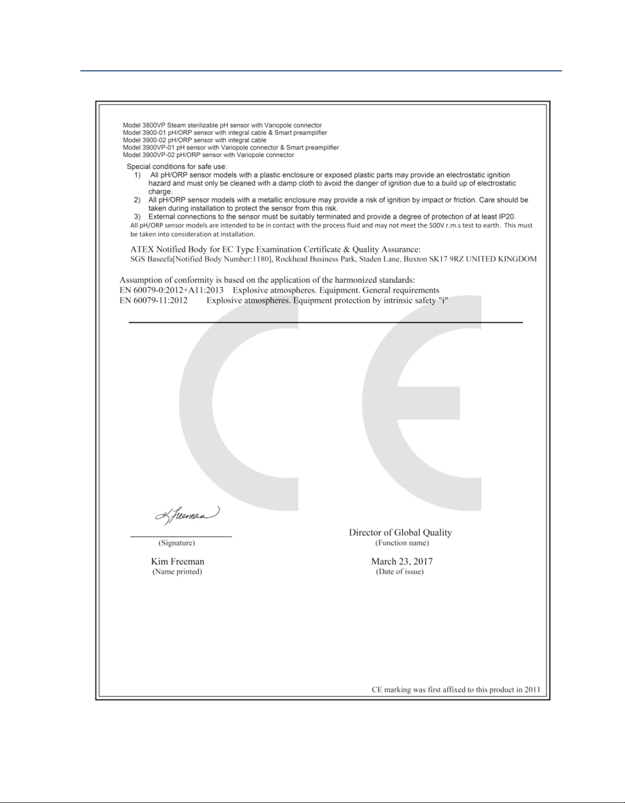
CAUTION
Special Conditions for Safe Use
. All pH/ORP sensors have a plastic enclosure which must only be cleaned with a damp cloth to avoid
1
the danger due to a build up of an electrostatic charge.
2. All pH/ORP sensor models are intended to be in contact with the process fluid and may not meet the
500V r.m.s. a.c. test to earth.
This must be taken into consideration at installation.
About This Document
This manual contains instructions for installation and operation of the Rosemount 396R and
396RVP pH/ORP Sensors.
The following list provides concerning all revisions of this document.
Rev. Level Date Notes
A 01/01 This is the initial release of the product manual. The manual has
been reformatted to reflect the Emerson documentation style
and updated to reflect any changes in the product offering.
B 07/02 Revised multiple drawings.
C 08/02 Added drawing #40105549, rev. D.
D 04/03 Revised drawing #40396R21/22 on page 18.
E 08/03 Added Silcore information.
F 09/04 Updated ordering info and added/revised wiring drawings.
G 01/05 Delete obsolete options.
H 01/07 Miscellaneous revisions.
I 11/10 Removed mention of patents and updated dnv logo.
J 02/11 Added ATEX directive and updated caution boxes per ANSI
standard.
K 03/17 Updated the Ordering Information, Specifications, Product
Certifications, and Emerson logo and Address.
Page 5

Instruction Manual Table of Contents
LIQ-MAN-396R-396RVP March 2017
Contents
Section 1: Description and Specifications
1.1 Features and Applications....................................................................................1
1.2 Specifications ......................................................................................................2
1.3 Product Certifications ..........................................................................................4
1.4 Ordering Information...........................................................................................5
Section 2: Installation
2.1 First Time Installation ..........................................................................................7
2.2 Unpacking and Inspection ...................................................................................8
2.3 Mechanical Installation ........................................................................................8
Section 3: Wiring Rosemount 396R
3.1 Wiring for Rosemount 396R...............................................................................17
Section 4: Wiring Rosemount 396RVP
4.1 Wiring for Rosemount 396RVP...........................................................................27
Section 5: Startup and Calibration
5.1 Sartup ...............................................................................................................43
5.2 pH Calibration ...................................................................................................43
5.3 ORP Calibration .................................................................................................44
Section 6: Maintenance
6.1 Maintenance......................................................................................................45
6.2 Sensor Removal .................................................................................................45
6.3 pH Electrode Cleaning .......................................................................................46
6.4 Cleaning Platinum Electrode..............................................................................46
6.5 Automatic Temperature Compensator...............................................................47
6.6 Sensor Tube Replacement When Used With A Sensor Head Junction Box............48
Section 7: Diagnostics and Troubleshooting
7.1 Diagnostics and Troubleshooting with Model 54/81/3081 pH/ORP....................51
Section 8: Accessories
8.1 Accessories........................................................................................................53
EC Declaration of Conformity.............................................................................55
Intrisicallly Safe Sensor Installation Drawing - FM ................................57
Table of Contents i
Page 6

Table of Contents Instruction Manual
March 2017 LIQ-MAN-396R-396RVP
ii Table of Contents
Page 7
Instruction Manual Description and Specifications
LIQ-MAN-396R-396RVP March 2017
Section 1: Description and Specifications
1.1 Features and Applications
Rosemount 396R and 396RVP Sensors are specifically designed for improved life in harsh, dirty
applications where a separate sample stream is difficult to provide and greater insertion depths are
required. These sensors are designed for use with a 1-1/4 in. or 1-1/2 in. ball valve for hot tap
installation. Sensors are constructed of molded polypropylene housed in a titanium tube with EPDM
seals to provide maximum chemical resistance. The sensors feature a shrouded tip for protection
from breakage while allowing process to flow by the glass electrode for accurate and reliable pH
and ORP measurements.
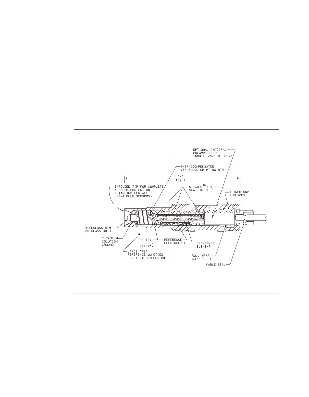
Figure 1-1: Cross Section Diagram of the TUpH Reference Technology
All TUpH sensors are designed with a large area reference junction, helical reference pathway, and an
AccuGlass pH glass bulb. This sensor technology ensures superior performance while only requiring
minimal maintenance.
Description and Specifications 1
Page 8
Description and Specifications Instruction Manual
March 2017 LIQ-MAN-396R-396RVP
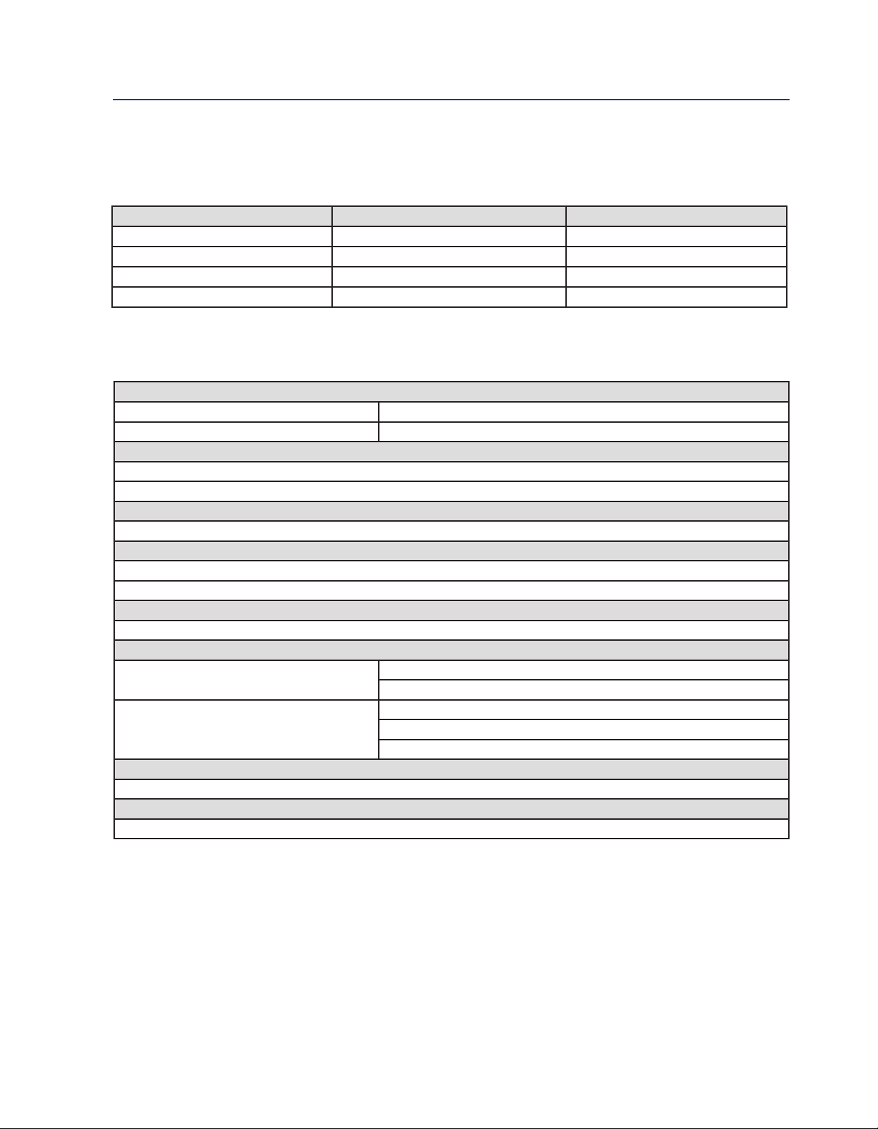
1.2 Specifications
able 1-1: Percent linearity over pH
T
pH Range Hemi Bulb Flat Bulb
0-2 pH 94% 93%
2-12 pH 99% 98%
12-13 pH 97% 95%
13-14 pH 92% --
Table 1-2: Rosemount 396R sensor specifications
Measured Range
pH range 0 to 14 pH
ORP range -1500 mV to 1500 mV
Maximum Pressure at Retraction or Insertion
Code 21: 64 psig (542 kPa abs)
Code 25: 35 psig (343 kPa abs)
Minimum Conductivity
100 µS/cm
Maximum Process Pressure and Temperature
Hemi bulb: 150 psig (1136 kPa abs) at 212 °F (100 °C)
Flat bulb: 100 psig (790 kPa abs) at 212 °F (100 °C)
Wetted Materials
Polypropylene, EPDM, titanium, glass, (platinum: ORP only)
Weight/Shipping Weight
Sensor Code 21: 2.0 lb/3.0 lb (.9 kg/1.40 kg)
Code 25: 3.0 lb/4.0 lb (1.40 kg/1.80 kg)
Ball Valve PN 23240-00; 5 lb/7 lb (2.25 kg /3.20 kg)
PN 23634-00 8 lb/10 lb (3.65 kg/4.55 kg)
J-Box: 3 lb/4 lb (1.40 kg/1.80 kg)
Process Connections
None, must use 1 inch process connector or ball valve kit (1-1/2 or 1-1/4 in.) (sold separately)
Cable Length
Integral 15 ft or 9.5 in. 9 conductor cable except option 60 (9.5 in. coaxial cable with BNC)
2 Description and Specifications
Page 9

Instruction Manual Description and Specifications
LIQ-MAN-396R-396RVP March 2017
Table 1-3: Rosemount 396RVP sensor specifications
Measured Range
pH range 0 to 14 pH
RP range
O
Maximum Pressure at Retraction or Insertion
Code 21: 64 psig (542 kPa abs)
Code 25: 35 psig (343 kPa abs)
Minimum Conductivity
75 µS/cm, nominal
Pressure Range
Hemi bulb 100-1136 kPa abs (0-150 psig)
Flat bulb 100-790 kPa abs (0-100 psig)
Wetted Materials
Polypropylene, EPDM, titanium, glass, (platinum: ORP only)
Weight/Shipping Weight
Sensor Code 21: 2.0 lb/3.0 lb (.9 kg/1.40 kg)
Ball Valve PN 23240-00; 5 lb/7 lb (2.25 kg /3.20 kg)
Process Connections
None, must use 1 inch process connector or ball valve kit (1-1/2 in. or 1-1/4 in.)
Cable Length
Use cable 24281-XX (where XX = -01 through -08 and designates various cable lengths). See accessories.
1500 mV to 1500 mV
-
Code 25: 3.0 lb/4.0 lb (1.40 kg/1.80 kg)
Description and Specifications 3
Page 10

Description and Specifications Instruction Manual
March 2017 LIQ-MAN-396R-396RVP
1.3 Product Certifications
Please see online certificates for further details.
ECEx
I
Sensors without preamp (pH and ORP) – Ex ia IIC T4 Ga (-20°C ≤ Ta ≤ +60°C)
Sensors with SMART preamp (pH only) – Ex ia IIC T4 Ga (-20°C ≤ Ta ≤ +60°C)
Per standards IEC60079-0 : 2011, IEC 60079-11 : 2011
ATEX
Sensors without preamp (pH and ORP) – II 1 G Ex ia IIC T4 Ga (-20˚C ≤ Ta ≤ +60˚C)
Sensors with SMART preamp (pH only) – II 1 G Ex ia IIC T4 Ga (-20˚C ≤ Ta ≤ +60˚C)
Per standards EN 60079-0: 2012+A11:2013, EN 60079-11:2012
FM
See online FM Certificate of Compliance for applicable sensor options:
Intrinsically Safe for use in Class I, II, and III, Division 1, Groups A, B, C, D, E, F, and G; Temperature
Class T6 Ta = -20 °C to +60 °C
Intrinsically Safe for use in Class I, Zone 0, AEx ia IIC T6 Ta = -20 °C to +60 °C
Nonincendive for use in Class I, Division 2, Groups A, B, C, and D; Temperature Class T6 Ta = -20 °C
to +60 °C
Suitable for use in Class II and III, Division 2, Groups E, F, and G; Temperature Class T6 Ta = -20 °C
to +60 °C Hazardous (Classified) Locations
IS/I,II,III/1/ABCDEFG/T6 Ta = 60°C - 1400332; Entity; I/0/AEx ia IIC/T6 Ta = 60 °C - 1400332; Entity;
NI/I/2/ABCD/T6 Ta = 60 °C; S/II,III/2/EFG/T6 Ta = 60 °C
Per standards 3600:1998, 3610:2010, 3611:2004, 3810:2005
CSA
See online CSA Certificate of Compliance for applicable sensor options:
Sensors with preamp – Intrinsically Safe:
Class I, Division 1, Groups ABCD; Class II, Division 1, Groups EFG; Class III; Class I, Division 2, Groups
ABCD; Ambient temperature rating -20 °C to +60 °C; Ex ia IIC; T6
Sensors without preamp – Intrinsically Safe and Non-Incendive:
Class I, Division 1, Groups ABCD; Class II, Division 1, Groups EFG; Class III; Class I, Division 2, Groups
ABCD; Ex ia IIC; T6; Ambient temperature rating -20 °C to +60 °C: (Simple Apparatus)
Per standards C22.2 No. 0-10, C22.2 No. 0.4-M2004, C22.2 No. 94-M1991, C22.2 No. 142 – M1987,
C22.2 No 157 – M1992, CAN/CSA E60079-0:07, CAN/CSA E60079- 11:02, UL50 11th Ed, UL508
17th Ed, UL913 7th Ed, UL 60079-0: 2005, UL 60079-11: 2002
4 Description and Specifications
Page 11

Instruction Manual Description and Specifications
LIQ-MAN-396R-396RVP March 2017
1.4 Ordering Information
Table 1-4: Rosemount 396R ordering information
odel
M
96R
3
Measuring Electrode Type
10 pH - GPHT Glass
12 ORP
13 pH - GPLR Flat Glass
Sensor Length
21 21 Inch Titanium Tube
25 36 Inch Titanium Tube
Transmitter/TC Compatibility
50 3K TC
54 Pt-100
Optional Cable Options
_ No Selection
60 9.5 Inch Cable with BNC
61 9.5 Inch Cable without BNC
Typical Model Number: 396R-10-21-54
ensor type
S
H/ORP Sensor
p
(1)
(2)
(3)
(4)
(5)
1. For use with legacy transmitter model 1181.
2. For use with Rosemount model 1056, 1057, 1066, 5081, and 56 transmitters.
3. The sensor will come with a standard 15 ft. integral cable.
4. Used for connection to 1181, 1054 series, and 2081 sensor head junction boxes.
5. Used for connection to sensor head junction box PN 23709-00.
Table 1-5: Rosemount 396RVP ordering information
Model Sensor type
396RVP pH/ORP Sensor
Measuring Electrode Type
10 pH - GPHT Glass
12 ORP
13 pH - GPLR Flat Glass
Sensor Length
21 21 Inch Titanium Tube
25 36 Inch Titanium Tube
Transmitter/TC Compatibility
50 3K TC
54 Pt-100
55 Pt-100 for SMART Preamplifier
(1)
(2)
(3)
Preamplifier Options
_ No Selection
70 SMART Preamplifier
Typical Model Number: 396RVP-10-21-55-70
(4)
1. For use with legacy transmitter model 1181.
2. For use with Rosemount model 1056, 1057, 1066, 5081, and 56 transmitters.
3. Must be selected with option 70. Also suitable for use with Rosemount model 1056, 1057, 1066, 5081, and 56 transmitters.
4. Must be selected with option 55.
Description and Specifications 5
Page 12

Description and Specifications Instruction Manual
March 2017 LIQ-MAN-396R-396RVP
6 Description and Specifications
Page 13

Instruction Manual Installation
LIQ-MAN-396R-396RVP March 2017
Section 2: Installation
2.1 First Time Installation
For first time Rosemount 396R installations, using the following guide is recommended:
1. Retractable Mounting
A. Choose one (required for all first time installations):
PN 23166-00, 1 in. x 1 in. NPT process connector, 316 SST
PN 23166-01, 1 in. x 1 in. NPT process connector, Titanium
B. Choose one:
PN 23240-00, 1-1/2 in. ball valve assembly, 316 SST
PN 23765-00, 1-1/4 in. ball valve assembly, 316 SST
2. Junction Boxes (Optional; Choose either Sensor Head or Remote)
A. Sensor Head Junction Boxes (used with options -60 or -61 sensor) - Choose one:
PN 23709-00; includes preamplifier
B. Remote Junction Boxes (used with standard 15 ft. cable length sensor) - Choose one:
PN 23555-00; includes preamplifier
3. Extension Cables - Choose one:
PN 23646-01, 11 conductor, shielded, prepped
PN 9200273, 11 conductor, shielded, unprepped
For first time Rosemount 396RVP installations, using the following guide is recommended:
1. Variopol Cable (required for all first time installations)
Choose one: PN 24281-00 -- 15 ft. VP8 Cable
PN 24281-01 -- 25 ft. VP8 Cable
2. Retractable Mounting
1A. Choose one (required for all first time installations, except as noted):
PN 23166-00 1 in. x 1 in. NPT process connector, 316 SST
PN 23166-01 1 in. x 1 in. NPT process connector, Titanium
Choose one (optional process connector o-rings):
PN 9550220, Kalrez ® O-ring, 2-214
PN 9550099, Viton ® O-ring, 2-214
1b. Choose one:
PN 23240-00 1-1/2 in. ball valve assembly, 316 SST
PN 23765-00 1-1/4 in. ball valve assembly, 316 SST (process connector not needed)
3. Remote Junction Boxes (Optional)
PN 23555-00 includes preamplifier
4. Extension cables
Choose one: PN 23646-01, 11 conductor, shielded, prepped
PN 9200273, 11 conductor, shielded, unprepped
Installation 7
Page 14
Installation Instruction Manual
March 2017 LIQ-MAN-396R-396RVP
2.2 Unpacking and Inspection
Inspect the outside of the carton for any damage. If damage is detected, contact the carrier
immediately. Inspect the instrument and hardware. Make sure all items in the packing list are
present and in good condition. Notify the factory if any part is missing.
Note: If the sensor is to be stored, the protective boot should be filled with either KCl electrolyte
solution or pH 4.0 buffer solution and replaced on sensor tip until ready to use.
Note: Save the original packing cartons and materials as most carriers require proof of damage due
to mishandling, etc. Also, if it is necessary to return the instrument to the factory, you must pack the
instrument in the same manner as it was received. Refer to Section 8.0 for instructions.
WARNING
Glass electrode must be wetted at all times (in storage and in line) to maximize sensor life.
2.3 Mechanical Installation
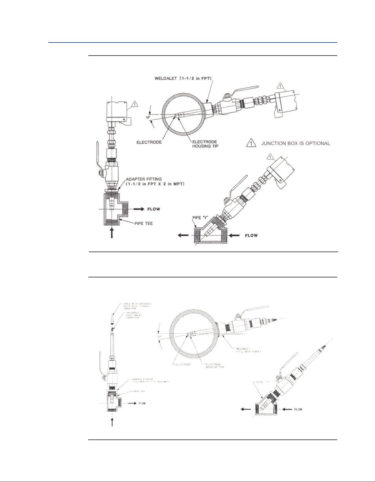
The Rosemount 396R Sensor may be installed through a weldalet or in a pipe tee or “Y”, as shown
in Figure 2-1, when used with a ball valve. Insert the end of the sensor to a depth sufficient to ensure
that the glass bulb is continuously wetted by the process fluid. The Rosemount 396R can also be
inserted directly into the process without the use of a ball valve for appli cations not requiring
continuous operation during sensor maintenance.
CAUTION
Allow sufficient room for safe retraction and insertion of the sensor. Personnel should have room for
stable footing while performing removal or insertion of the sensor.
The sensor must be mounted within 10-90 degrees of the horizontal with the tip pointed
downward, thus keeping air bubbles off of the pH sensitive glass bulb. Bubbles settled on the glass
bulb disrupt the electrical continuity between the pH sensitive glass and the silver/ silver chloride
measuring element.
If the retraction version is to be installed without a ball valve follow the installation procedure for
insertion service (Section 2.3.2). Perform the following steps for sensor installation through a ball
valve:
2.3.1 Installation Through Ball Valve
1. Carefully remove the liquid filled rubber boot which protects the glass electrode and keeps
the liquid junction wet during shipping and storage. Discard the liquid and boot. Make sure
the lubricated O-ring is in place in the groove inside the male connector on the sensor body.
CAUTION
Buffer solution, in the protective boot, may cause skin or eye irritation.
2. With the male connector on the sensor’s body, insert the sensor into the ball valve until it
gently touches the closed valve. The molded electrode guard will protect the glass bulb
from breakage.
8 Installation
Page 15
Instruction Manual Installation
LIQ-MAN-396R-396RVP March 2017
3. Thread the male connector body tightly into the ball valve assembly. DO NOT tighten the
hex nut on the male connector body; doing so would not allow the sensor to be inserted
through the ball valve.
4. Pull back hard on the sensor assembly, as if trying to remove the sensor, to be certain that
the sensor cannot come free of the ball valve assembly. The built-in retraction stop will butt
against the shoulder of the male connector if properly installed.
CAUTION
The sensor must be captured by the valve assembly and the male connector so that it cannot be blown
free by process pressure if mishandled during insertion or retraction.
5. After confirming that the sensor assembly is properly secured by the valve assembly, the
valve may be opened and the sensor positioned into the process at the desired depth and
orientation.
6. While holding the sensor in position, tighten the hex nut of the male connector to firmly
secure the sensor in place. When the hex nut is tightened, the Teflon ferrule inside the
compression fitting clamps the sensor tube.
CAUTION
Over tightening the hex nut may damage the ferrule.
NOTICE
A stainless steel ferrule is available if the Teflon ferrule does not inadequately grip. When using the
metallic ferrule, care must be taken to avoid over tightening and damaging the sensor tube. If the male
connector leaks during insertion or retraction, replace the O-ring in the male connector.
2.3.2 Installation Without Ball Valve
The Rosemount 396R Sensor may be installed through a weldalet or pipe tee or “Y” when used with
a process connector (PN 23166-00 or 23166-01). The sensor should be installed within 80° of
vertical, with the electrode facing down.
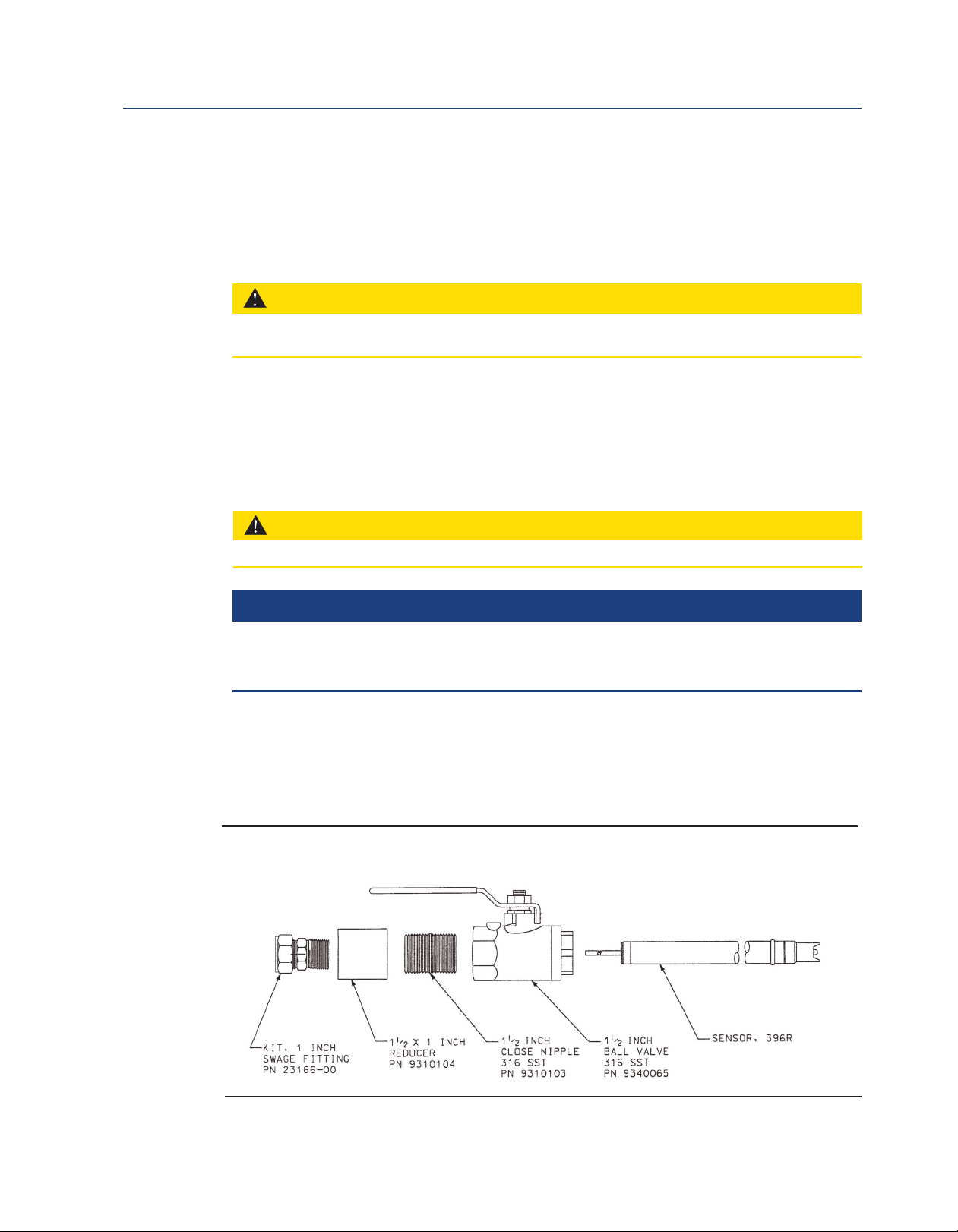
Figure 2-1: Exploded View of Ball Valve Kit PN 23240-00 used with process connector
PN 23166-00 (or PN 23166-01)
Installation 9
Page 16
Installation Instruction Manual
March 2017 LIQ-MAN-396R-396RVP
Figure 2-1: Typical Mounting Configurations for Rosemount 396R
Figure 2-2: Typical Mounting Configurations for Rosemount 396RVP
10 Calibration and Maintenance
Page 17
Instruction Manual Installation
LIQ-MAN-396R-396RVP March 2017
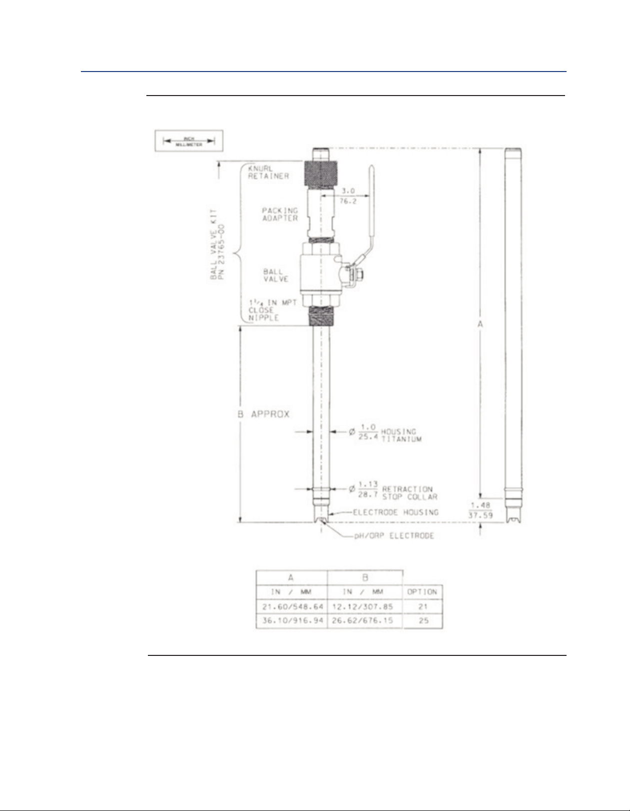
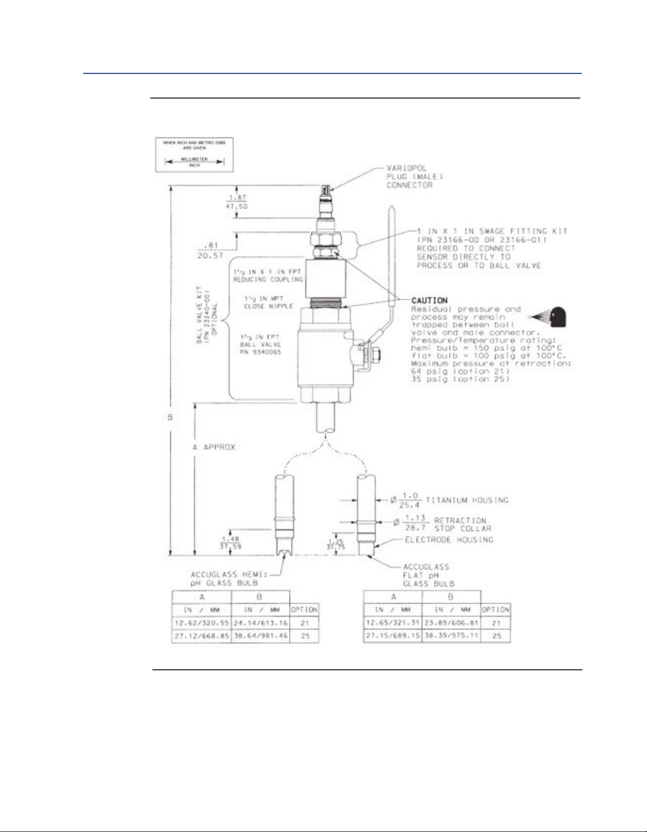
Figure 2-3: Dimensional Drawing — Rosemount 396R with Optional Ball Valve PN 23765-00
Note: Add five (5) inches to dimension A if mounting a sensor head junction box onto the sensor.
Calibration and Maintenance 11
Page 18
Installation Instruction Manual
March 2017 LIQ-MAN-396R-396RVP
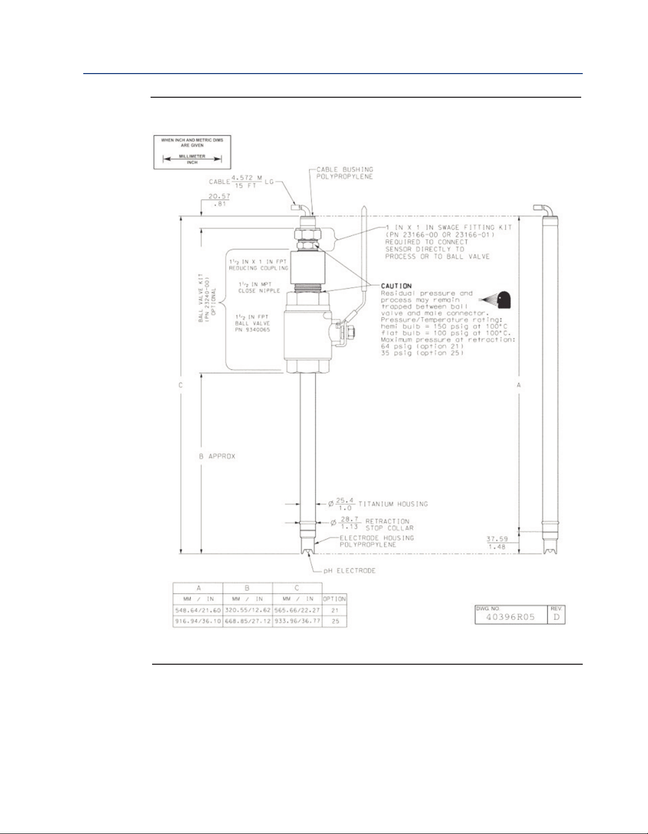
igure 2-4: Dimensional Drawing — Rosemount 396R with Optional Ball Valve PN 23240-00
F
Note: Add five (5) inches to dimension A if mounting a sensor head junction box onto the sensor.
12 Installation
Page 19
Instruction Manual Installation
LIQ-MAN-396R-396RVP March 2017
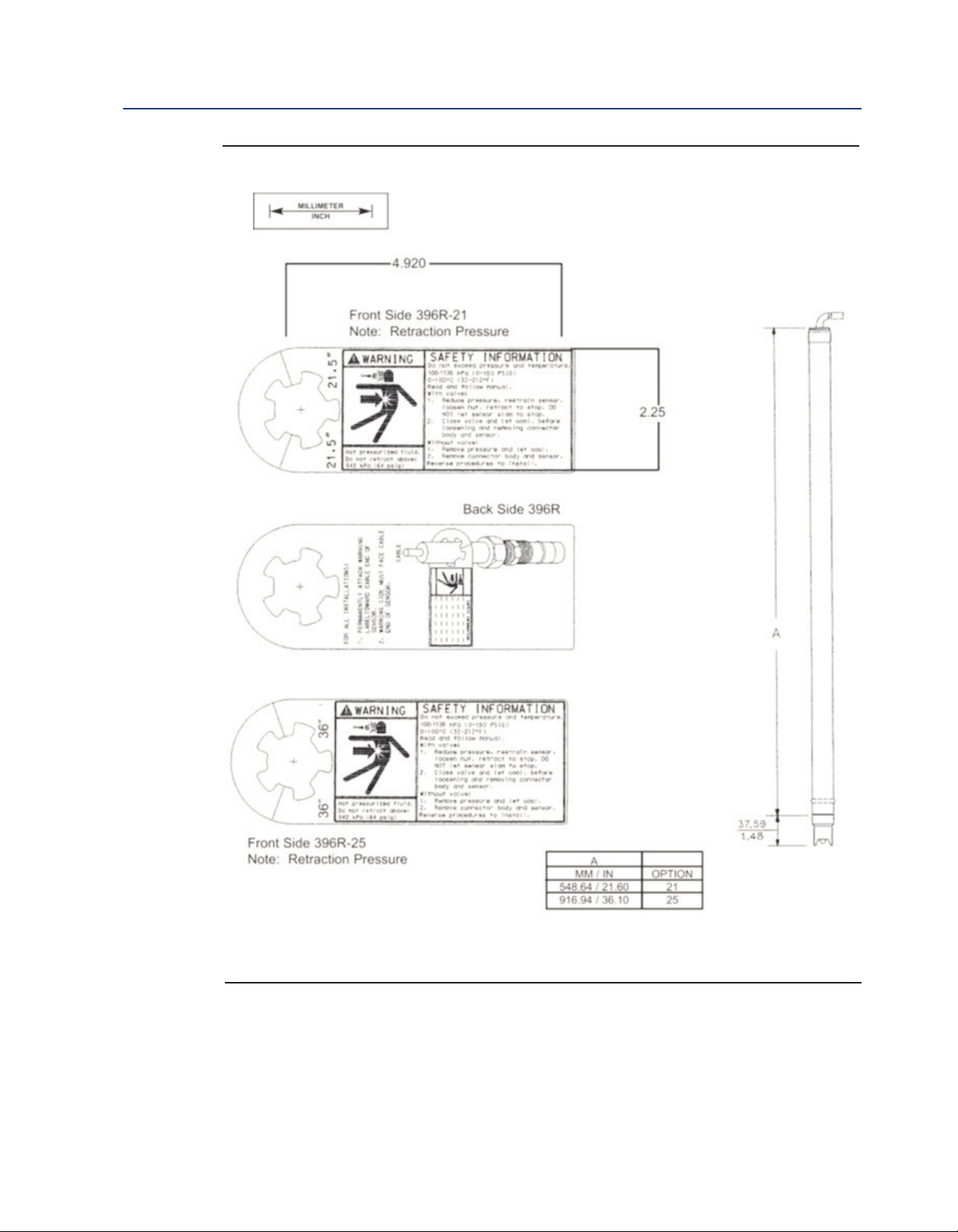
Figure 2-5: Dimensional Warning Label for Rosemount 396R Hemi Bulb Sensors and Sensor
Note: Pressure rating for flat glass sensors is 100-790 kPa (0-100 psig).
Installation 13
Page 20
Installation Instruction Manual
March 2017 LIQ-MAN-396R-396RVP
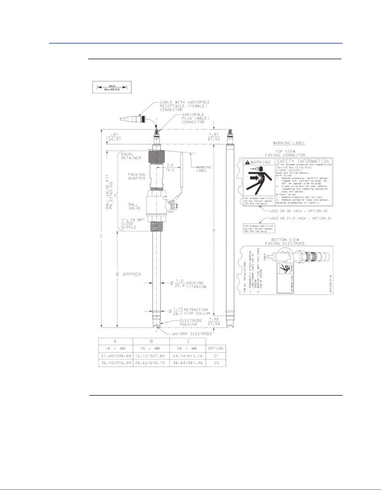
Figure 2-6: Dimensional Drawing — Rosemount 396RVP with Optional 1-1/2 inch Ball Valve
PN 23240-00
14 Installation
Page 21
Instruction Manual Installation
LIQ-MAN-396R-396RVP March 2017
Figure 2-6: Dimensional Drawing — Rosemount 396RVP with Optional 1-1/4 inch Ball Valve
PN 23765-00
Installation 15
Page 22

Installation Instruction Manual
March 2017 LIQ-MAN-396R-396RVP
16 Installation
Page 23

Instruction Manual Wiring Rosemount 396R
LIQ-MAN-396R-396RVP March 2017
Section 3: Wiring Rosemount 396R
3.1 Wiring for Rosemount 396R
Make electrical connections as shown on Figures 3-1 through 3-15 using the following guidelines.
For wiring Rosemount 396RVP, see Section 4.
1. Pay particular attention to the analyzer or transmitter model number when following
details on the wiring diagrams to ensure that the connections are made to the proper
terminals.
2. Use Rosemount custom cable Part Number 9200273 for interconnect.
3. The maximum distance from the sensor to the transmitter is 15 ft without an integral
preamplifier.
4. Signal cable should be run in a dedicated conduit and should be kept away from AC power
lines.
NOTICE
For maximum EMI/RFI protection when wiring from the sensor to the junction box, the outer braid of
the sensor should be connected to the outer braided shield of the extension cable. The outer braid of the
extension cable to the instrument must be terminated at earth ground or by using an appropriate metal
cable gland fitting, that provides a secure connection to the instrument cable.
Figure 3-1: Cable Preparation Instructions (PN 9200274)
Wiring Rosemount 396R 17
Page 24

Wiring Rosemount 396R Instruction Manual
March 2017 LIQ-MAN-396R-396RVP
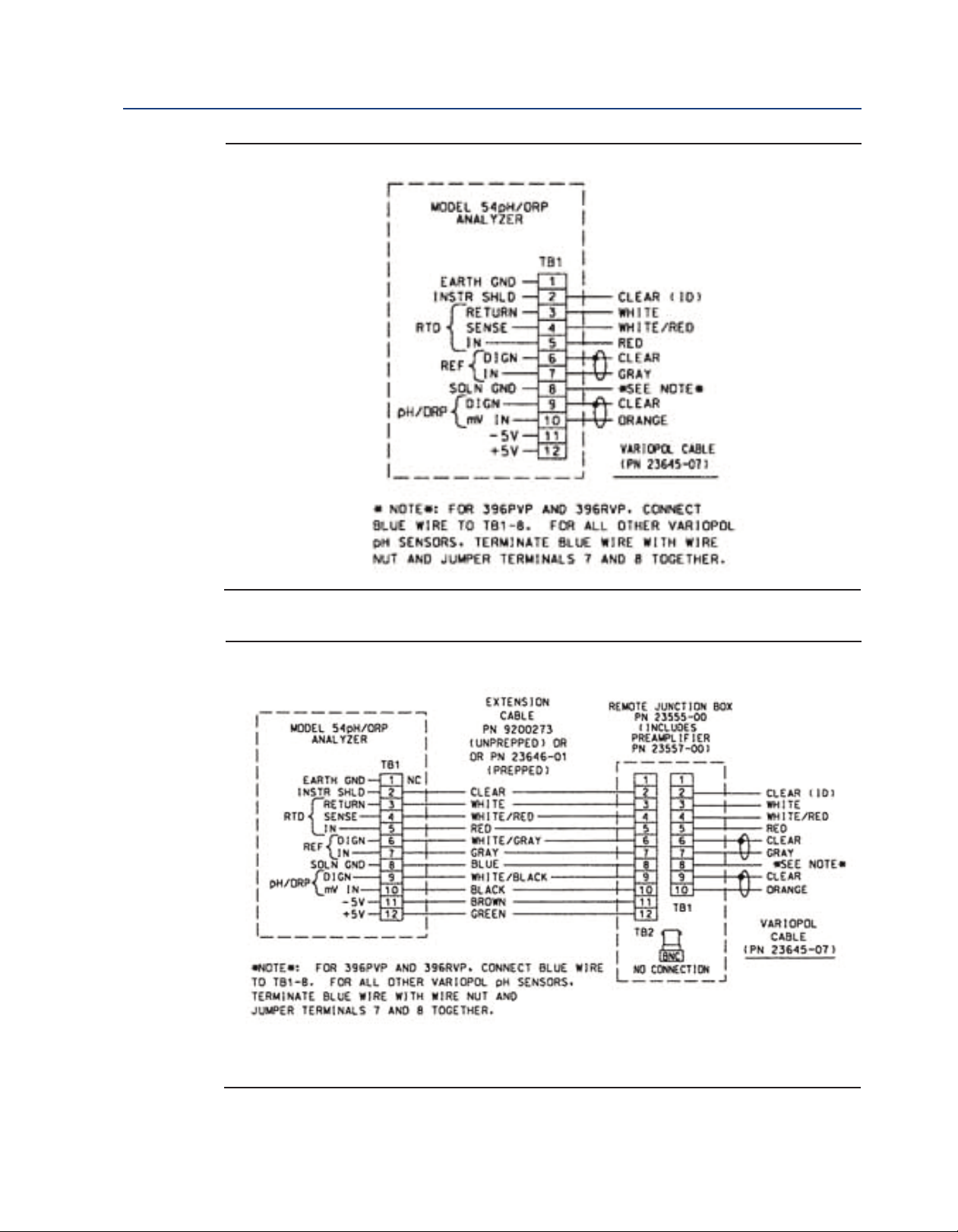
Figure 3-2: Wiring Rosemount 396R-54 to Models 54e, 81, 3081, 4081, and 5081 pH/ORP
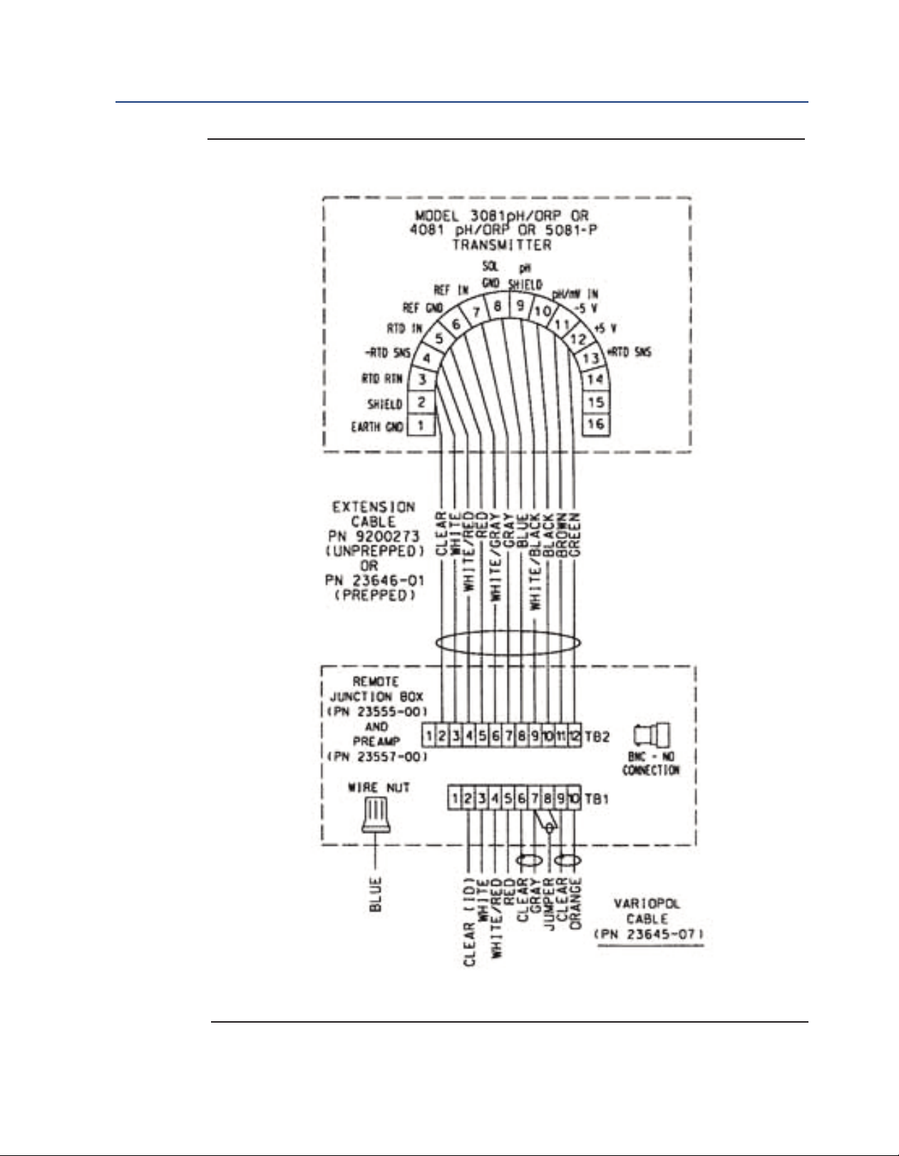
Figure 3-3: Wiring Rosemount 396R-54 with Remote J-Box and Preamp (PN 23555-00)
18 Wiring Rosemount 396R
Page 25

Instruction Manual Wiring Rosemount 396R
LIQ-MAN-396R-396RVP March 2017
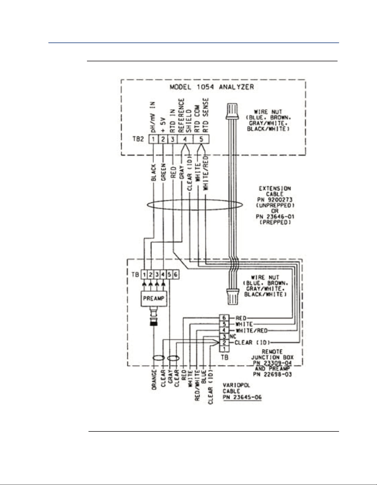
Figure 3-4: Wiring Rosemount 396R-50 for use with Remote Junction Box (PN 23309-03)
Figure 3-5: Wiring Rosemount 396R-54 for use with Remote Junction Box (PN 23309-04)
Wiring Rosemount 396R 19
Page 26

Wiring Rosemount 396R Instruction Manual
March 2017 LIQ-MAN-396R-396RVP
igure 3-6: Wiring Rosemount 396R-50/54 to Model 1181 pH/ORP
F
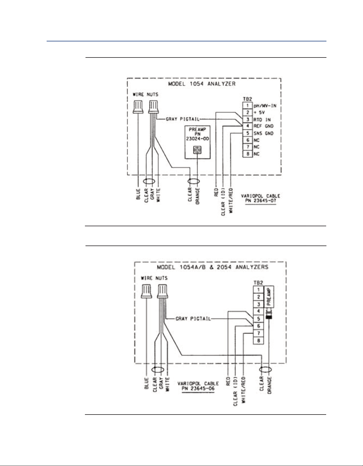
Figure 3-7: Wiring Rosemount 396R-54 to Models 1054A/B pH/ORP, 2054 pH, and 2081
pH/ORP
20 Wiring Rosemount 396R
Page 27
Instruction Manual Wiring Rosemount 396R
LIQ-MAN-396R-396RVP March 2017
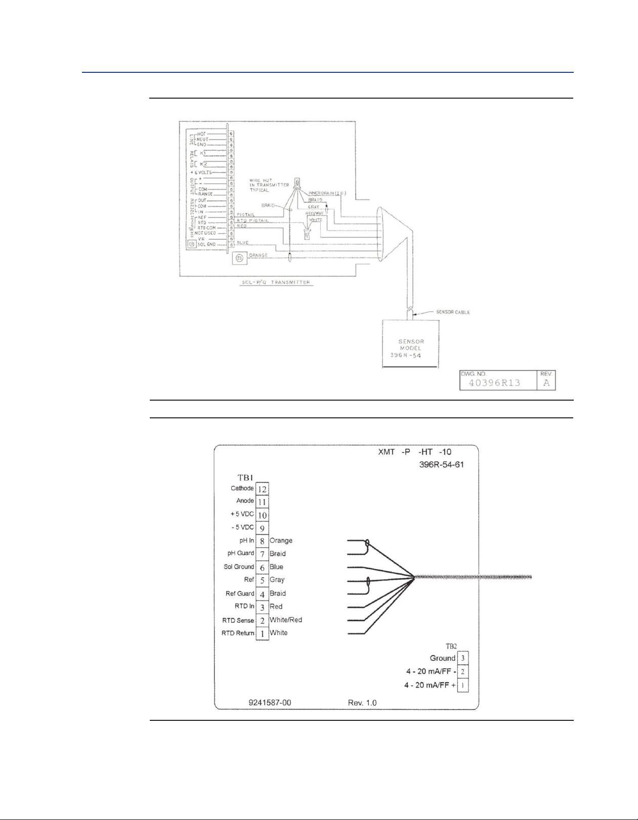
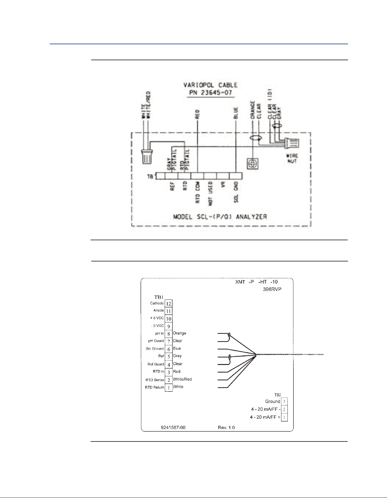
igure 3-8: Wiring Rosemount 396R-54 to Model SCL-(P/Q)
F
Figure 3-9: Wiring Rosemount 396R-54-61 to Model Xmt-P-XX-10
Wiring Rosemount 396R 21
Page 28

Wiring Rosemount 396R Instruction Manual
March 2017 LIQ-MAN-396R-396RVP
Figure 3-10: Wiring Rosemount 396R-50/54-60 for use with Sensor Head J-Boxes to Models
1181, 1054 Series, 2054, 2081
Figure 3-11: Wiring Rosemount 396R-54-61 for use with Sensor Head J-Box to Models 54e,
81, 3081, 4081, and 5081
22 Wiring Rosemount 396R
Page 29
Instruction Manual Wiring Rosemount 396R
LIQ-MAN-396R-396RVP March 2017
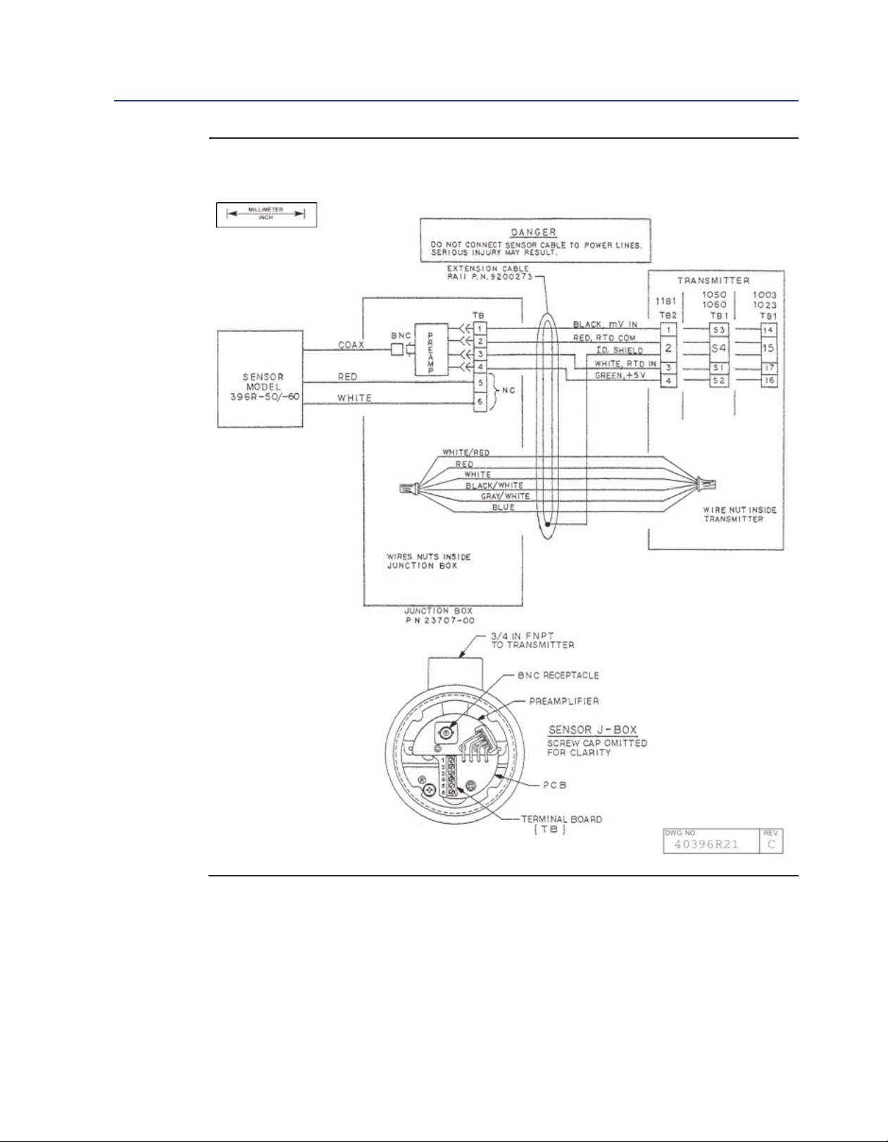
igure 3-12: Wiring Rosemount 396R-50 for use with J-Box (PN 23707-00) to Models 1181,
F
1050, 1060, 1030, and 1023 pH Transmitters
Wiring Rosemount 396R 23
Page 30

Wiring Rosemount 396R Instruction Manual
March 2017 LIQ-MAN-396R-396RVP
igure 3-13: Wiring Rosemount 396R-54 for use with J-Box (PN 23708-01) to Models 1054
F
Series, 2054, and 2081 pH Transmitters
24 Wiring Rosemount 396R
Page 31
Instruction Manual Wiring Rosemount 396R
LIQ-MAN-396R-396RVP March 2017
Figure 3-14: Wiring Rosemount 396R-50/54-60 for use with Sensor Head J-Boxes to Models
1181, 1054 Series, 2054, 2081
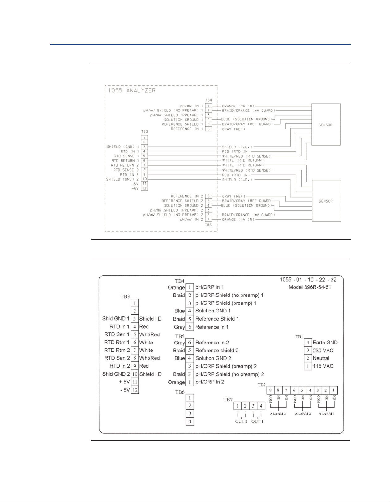
Figure 3-15: Wiring Rosemount 396R-54-61 to Model 1055-10-22-32
Wiring Rosemount 396R 25
Page 32

Wiring Rosemount 396R Instruction Manual
March 2017 LIQ-MAN-396R-396RVP
26 Wiring Rosemount 396R
Page 33

Instruction Manual Wiring Rosemount 396RVP
LIQ-MAN-396R-396RVP March 2017
Section 3: Wiring Rosemount 396RVP
3.1 Wiring for Rosemount 396RVP
Make electrical connections as shown on Figures 4-1 through 4-20 using the following guidelines.
For wiring Rosemount 396R, see Section 3.
1. Pay particular attention to the analyzer or transmitter model number when following
details on the wiring diagrams to ensure that the connections are made to the proper
terminals.
2. The Rosemount 396RVP uses a mating VP cable. See attached wiring sheet for wire
functions of the cables and wiring diagrams to various transmitters.
3. The maximum distance from the sensor to the transmitter is 15 ft without an integral
preamplifier.
4. Signal cable should be run in a dedicated conduit and should be kept away from AC power
lines.
NOTICE
For maximum EMI/RFI protection when wiring from the sensor to the junction box, the outer braid of
the sensor should be connected to the outer braided shield of the extension cable. The outer braid of the
extension cable to the instrument must be terminated at earth ground or by using an appropriate metal
cable gland fitting, that provides a secure connection to the instrument cable.
Wiring Rosemount 396RVP 27
Page 34
Wiring Rosemount 396RVP Instruction Manual
March 2017 LIQ-MAN-396R-396RVP
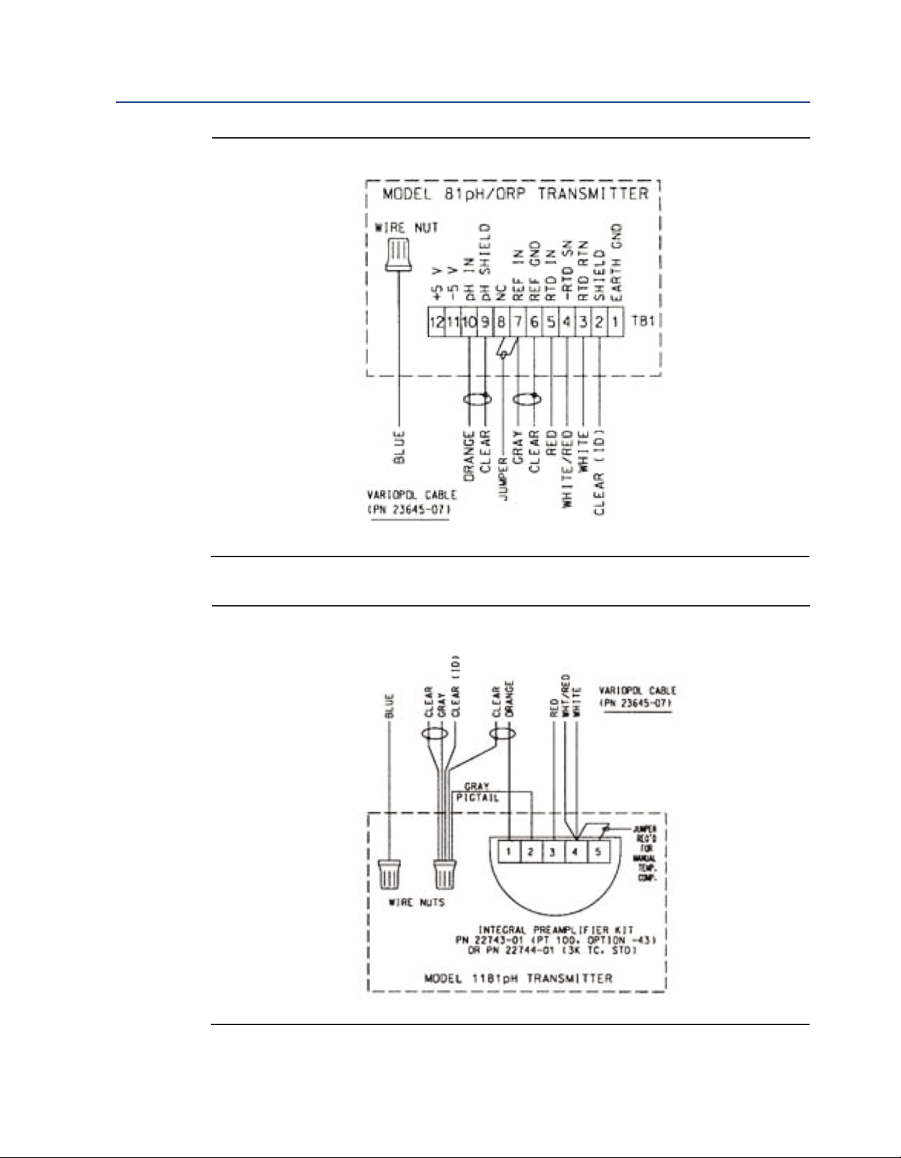
Figure 4-1: Model 81 Wiring
Figure 4-2: Model 1181 Wiring
28 Wiring Rosemount 396RVP
Page 35
Instruction Manual Wiring Rosemount 396RVP
LIQ-MAN-396R-396RVP March 2017
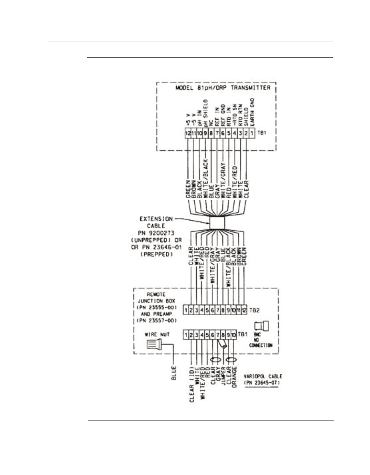
igure 4-3: Model 81 Wiring through Remote Junction Box
F
Wiring Rosemount 396RVP 29
Page 36

Wiring Rosemount 396RVP Instruction Manual
March 2017 LIQ-MAN-396R-396RVP
Figure 4-4: Model 1181, 1050/1060, & 1003/1023 Wiring through Remote Junction Box
30 Wiring Rosemount 396RVP
Page 37

Instruction Manual Wiring Rosemount 396RVP
LIQ-MAN-396R-396RVP March 2017
Figure 4-5: Model 2081 Wiring
Figure 4-6: Model 3081, 4081, and 5081 Wiring
Wiring Rosemount 396RVP 31
Page 38

Wiring Rosemount 396RVP Instruction Manual
March 2017 LIQ-MAN-396R-396RVP
Figure 4-7: Model 2081 Wiring through Remote Junction Box
32 Wiring Rosemount 396RVP
Page 39
Instruction Manual Wiring Rosemount 396RVP
LIQ-MAN-396R-396RVP March 2017
Figure 4-8: Model 3081, 4081, and 5081 Wiring through Remote Junction Box
Wiring Rosemount 396RVP 33
Page 40
Wiring Rosemount 396RVP Instruction Manual
March 2017 LIQ-MAN-396R-396RVP
igure 4-9: Model 1054 Wiring
F
Figure 4-10: Model 1054A/B & 2054 Wiring
34 Wiring Rosemount 396RVP
Page 41
Instruction Manual Wiring Rosemount 396RVP
LIQ-MAN-396R-396RVP March 2017
igure 4-11: Model 1054 Wiring through a Remote Junction Box
F
Wiring Rosemount 396RVP 35
Page 42

Wiring Rosemount 396RVP Instruction Manual
March 2017 LIQ-MAN-396R-396RVP
Figure 4-12: Model 1054A/B & 2054 Wiring through a Remote Junction Box
36 Wiring Rosemount 396RVP
Page 43
Instruction Manual Wiring Rosemount 396RVP
LIQ-MAN-396R-396RVP March 2017
Figure 4-13: Model 54/54e Wiring
Figure 4-14: Model 54 Wiring through Remote Junction Box
Wiring Rosemount 396RVP 37
Page 44

Wiring Rosemount 396RVP Instruction Manual
March 2017 LIQ-MAN-396R-396RVP
Figure 4-15: Model 2700 Wiring
38 Wiring Rosemount 396RVP
Page 45
Instruction Manual Wiring Rosemount 396RVP
LIQ-MAN-396R-396RVP March 2017
Figure 4-16: Model SCL-(P/Q) Wiring
Figure 4-17: Model Xmt-P-XX-10 Wiring
Wiring Rosemount 396RVP 39
Page 46

Wiring Rosemount 396RVP Instruction Manual
March 2017 LIQ-MAN-396R-396RVP
Figure 4-18: Model 1055pH/pH Wiring
Figure 4-19: Model 1055pH/pH Wiring through Remote Junction Boxes
40 Wiring Rosemount 396RVP
Page 47

Instruction Manual Wiring Rosemount 396RVP
LIQ-MAN-396R-396RVP March 2017
Figure 4-20: Model 1055-10-22-32 Wiring
Wiring Rosemount 396RVP 41
Page 48

Wiring Rosemount 396RVP Instruction Manual
March 2017 LIQ-MAN-396R-396RVP
42 Wiring Rosemount 396RVP
Page 49

Instruction Manual Wiring Rosemount 396RVP
LIQ-MAN-396R-396RVP March 2017
Section 5: Startup and Calibration
5.1 Sartup
To obtain best accuracy, the sensor must be calibrated as a loop with the transmitter. Please refer
to the respective transmitter instruction manual for proper calibration procedures.
5.2 pH Calibration
1. After a temporary connection is established between the sensor and the instrument, a
buffer calibration may be performed.
2. Consult appropriate pH/ORP transmitter instruction manual for specific calibration and
standardization procedures or see below for recommended two point buffer calibration
procedure.
5.2.1 Recommended two point buffer calibration procedure
Select two stable buffer solutions, preferably pH 4.0 and 7.0 (pH buffers other than pH 4.0 and
pH 7.0 can be used as long as the pH values are at least two pH units apart).
NOTICE
A pH 7 buffer solution reads a mV value of approx. zero, and pH buffers read approx. +/- 59.1 mV for each
pH unit above or below pH 7. Check the pH buffer manufacturer specifications for millivolt values at
various temperatures since it may affect the actual value of the buffer solution mV/pH value.
1. Immerse sensor in the first buffer solution. Allow sensor to adjust to the buffer
temperature (to avoid errors due to temperature differences between the buffer solution
and sensor temperature) and wait for reading to stabilize. Value of buffer can now be
acknowledged by transmitter.
2. Once the first buffer has been acknowledged by the transmitter, rinse the buffer solution
off of the sensor with distilled or deionized water.
3. Repeat steps 1 and 2 using the second buffer solution.
4. Once the transmitter has acknowledged both buffer solutions, a sensor slope (mV/pH) is
established (the slope value can be found within the transmitter).
5. The slope value should read about 59.1 mV/pH for a new sensor and will decrease over
time to approximately 47 - 49 mV/pH. Once the slope reads below the 47-49 mV/pH range,
a new sensor should be installed to maintain accurate readings.
Startup and Calibration 43
Page 50

Startup and Calibration Instruction Manual
March 2017 LIQ-MAN-396R-396RVP
5.2.2 Recommended pH Sensor Standardization
For maximum accuracy, the sensor can be standardized on-line or with a process grab sample after
a buffer calibration has been performed and the sensor has been conditioned to the process.
tandardization accounts for the sensor junction potential and other interferences.
S
Standardization will not change the sensor’s slope but will simply adjust the transmitters reading
to match that of the known process pH.
1. While obtaining a process solution sample (it is recommended that the sample is taken
close to the sensor), record the pH value that is shown on the transmitter display.
2. Measure and record the pH of the process solution sample with a another temperature
compensated, calibrated pH instrument. For best results, standardization should be
performed at the process temperature.
3. Adjust the transmitter value to the standardized value.
5.3 ORP Calibration
An ORP loop is best calibrated using an ORP standard solution. Most industrial applications have a
number of ORP reactions occurring in sequence or simultaneously. There can be several
components that are oxidized or reduced by the reagents that are used. Theoretically, the ORP
potential is absolute because it is the result of the oxidation- reduction equilibrium. However, the
actual measured potential is dependent on many factors, including the condition of the surface of
the ORP platinum electrode. Therefore, the sensor should be allowed 1-2 hours to become
“conditioned” to the stream when first set-up or after being cleaned.
5.3.1 ORP Calibration Procedure
1. Make a temporary electrical connection between the sensor and the instrument.
2. Obtain a ORP standard solution (PN R508-8oz) or one can be made quite simply by adding
a few crystals of quinhydrone to either pH 4 or pH 7 buffer. Quinhydrone is only slightly
soluble; therefore, only a few crystals will be required.
3. Immerse the sensor in the standard solution. Allow 1-2 minutes for the ORP sensor to
stabilize.
4. Adjust the standardize control of the instrument to the solution value shown in Table 5-1.
The resulting potentials, measured with a clean platinum electrode and saturated KCl/AgCl
reference electrode, should be within ±20 millivolts of the value shown in Table 5-1.
Solution temperature must be noted to insure accurate interpretation of results. The ORP
value of saturated quinhydrone solution is not stable over long periods of time. Therefore,
these standards should be made up fresh each time they are used.
5. Remove the sensor from the buffer, rinse and install in the process.
Table 5-1: ORP of Saturated Quinhydrone Solution
pH 4 pH 7
Temperature °C 20 25 30 20 25 30
Millivolt Potential 268 264 260 94 87 80
44 Startup and Calibration
Page 51

Instruction Manual Maintenance
LIQ-MAN-396R-396RVP March 2017
Section 6: Maintenance
6.1 Maintenance
osemount 396R and 396RVP sensors are disposable type sensors and require minimum
R
maintenance. These sensors should be removed from the process periodically and checked in buffer
solutions. If the sensor will not calibrate, refer to your transmitter instruction manual for proper
test procedures. If the sensor has failed, it should be discarded and replaced.
6.2 Sensor Removal
Please refer to the appropriate paragraph for instructions regarding removal of the sensor for
periodic maintenance.
6.2.1 Retractable Version
WARNING
System pressure may cause the sensor to blow out with great force unless care is taken during removal.
Make sure the following steps are adhered to.
A. Rosemount 396R-21 (21 in. tube)
1. Be certain system pressure at the sensor is below 64 psig (542 kPa) before
proceeding with the retraction. It is also recommended that the personnel wear
a face shield and have a stable footing. Refer to Figure 6-1. Push in on the sensor
end or the top of the J-box and slowly loosen the hex nut (B) of the process end
male connector (A).
B. Rosemount 396R-25 (36 in. tube)
2. Be certain that pressure at the sensor is below 35 psig (343 KPa) before proceeding
with the retraction. It is also recommended that the personnel wear a face shield
and have a stable footing. Refer to Figure 6-1. Push in on the sensor end or the top
of the J-box and slowly loosen the hex nut (B) of the process end male
connector (A).
CAUTION
Do not remove nut at this time.
3. When the hex nut is loose enough, slowly ease the sensor back completely until
the retraction stop collar is reached.
CAUTION
Failure to withdraw the sensor completely may result in damage to the sensor when the valve is closed.
4. Close the ball valve slowly. If there is resistance, the valve may be hitting the
sensor. Double check that the sensor has been retracted to the retraction stop
collar.
Maintenance 45
Page 52
Maintenance Instruction Manual
March 2017 LIQ-MAN-396R-396RVP
WARNING
efore removing the sensor from the ball valve, be absolutely certain that the ball valve is fully closed.
B
Leakage from the male connector threads may indicate that the male connector is still under pressure.
Leakage through a partially open valve could be hazardous, however with the ball valve closed, some
esidual process fluid may leak from the connector's pipe threads.
r
5. The Male Connector Body (A) may now be completely unthreaded from the
reducing coupling and the sensor removed for servicing.
CAUTION
If the male connector leaks during insertion or retraction, replace the O-ring (PN 9550099) in the male
connector A.
6.3 pH Electrode Cleaning
If the electrode is coated or dirty, it may be cleaned as follows:
1. Remove the sensor from process as instructed in Section 6.2.
2. Wipe the glass bulb with a soft, clean, lint free cloth or tissue. If this does not remove the
dirt or coating, proceed to step 3. If the sensor appears to be clean, go to step 5.
3. Wash the glass bulb in a strong detergent solution and thoroughly rinse with tap water. If
the bulb still appears to have a coating, proceed to step 4.
CAUTION
The solution used in the following step is an acid and should be handled with care. Follow the directions
of the acid manufacturer. Wear the proper protective equipment. Do not let the solution come in
contact with skin or clothing. If contact with the skin is made, immediately rinse with clean water.
4. Following the caution above, wash the glass bulb in dilute 5% hydrochloric acid solution
and then rinse it thoroughly in tap water. Replace the sensor if it cannot be cleaned. If the
glass bulb appears clean, proceed to step 5.
5. Buffer calibrate the sensor (Refer to Section 5). If the sensor appears to respond
sluggishly to pH change, soaking it overnight in a weak acid solution (5% hydrochloric acid)
may improve its response. Be sure to follow the CAUTION above and to rinse the sensor’s
tip thoroughly with tap water. If the sensor will not calibrate, it must be replaced.
6.4 Cleaning Platinum Electrode
The electrode is never exposed to these undesirable compounds. In the event poisoning is
suspected, the electrode can be restored to normal operation by simply cleaning the platinum
electrode with baking soda. Polish it by rubbing it with a damp paper towel and baking soda until
a bright, shiny appearance is attained.
46 Maintenance
Page 53
Instruction Manual Maintenance
LIQ-MAN-396R-396RVP March 2017
6.5 Automatic Temperature Compensator
The temperature compensator element is temperature sensitive and can be checked with an
ohmmeter. Resistance increases with temperature.
The 3K element will read 3000 ohms ±1% at 25°C (77°F) and a Pt-100 will read 110 ohms. Resistance
varies with temperature for a 3K and Pt-100 element and can be determined according to
Table 6-2 or the following formula:
RT=R0[l+R1(T-20)]
Where RT= Resistance
T = Temperature in °C
Refer to Table 4-1 for R0and R1values
Table 6-1: R0and R1Values for Temperature Compensation Elements
Temperature Element R
3K 2934 0.0045
PT-100 107.7 0.00385
0
R
1
Table 6-2: Temperature vs Resistance of Automatic Temperature Compensator Elements
Temperature °C Resistance (Ohms) ±1%
3K PT-100
0 2670 100.0
10 2802 103.8
20 2934 107.7
25 3000 109.6
30 3066 111.5
40 3198 115.4
50 3330 119.2
60 3462 123.1
70 3594 126.9
80 3726 130.8
90 3858 134.6
100 3990 138.5
Maintenance 47
Page 54

Maintenance Instruction Manual
March 2017 LIQ-MAN-396R-396RVP
6.6 Sensor Tube Replacement When Used With A
Sensor Head Junction Box
Replace ment of the retraction versions sensor tube assembly involves the removal and installation
of two sets of male connectors: One at the process end of the sensor, and the other at the junction
box end (See Figures 6-1, 6-2). Refer to Section 6.2 for proper removal of the sensor from process.
1. Remove sensor from process before proceeding. The junction box with attached male
connector must be recovered from the old sensor for reuse. Unscrew the junction box cover
and set aside. Disconnect electrical connections from printed circuit board inside junction
box. Disconnect BNC connector to preamp. Unscrew hex nut (D) from male connector
body (C). Separate junction box from used sensor. Set aside.
2. Pry off split ferrule from sensor and set aside for reuse. Remove hex nut (D) and set aside
for reuse. Check that the internal O-ring is in place in the male connector body (C) attached
to the junction box.
3. Remove hex nut (B) from male connector body (A) at process end of sensor and set aside.
Slide the Teflon ferrule and the male connector off sensor in the direction of junction box
and set.
NOTICE
If stainless steel ferrule was used, male connector body (A) will have to be discarded with the sensor tube.
4. Discard used O-ring from male connector body (A). Coat new O-ring with a thin film of the
O-ring lubricant provided. Position it in the machined Oring groove in place of the
discarded O-ring.
CAUTION
Make sure lubricant does not contact any part of the sensor tip particularly the glass bulb.
5. Cover the 1" MNPT pipe threads of the male connector body (A) with Teflon tape (not
provided) to protect them from galling during reinstallation.
6. Pass the wires from the new sensor through the process end male connector (A). Make
sure that the beveled edge of the ferrule faces the process end of the sensor. Snug the hex
nut (B) to keep it in place. Do not tighten down fully on the hex nut at this time.
7. Pass the wires from the new sensor through the hex nut (D), the split ferrule (from the old
sensor), male connector body (C), O-ring, and through the junction box from the “neck”
opening and out to the printed circuit board in the junction box. Butt the ferrule’s beveled
edge and the sensor tube against the junction male connector (C). Screw the hex nut (D)
by hand until the tube is “locked” into the male connector body. Make sure that the male
connector body (C) is sufficiently tightened. The sensor will “click” into place by pulling
the sensor tube away from the junction box, but will not move from side to side or pull
clear of the male connector. If the sensor tube is correctly attached to the junction box,
wrench tighten hex nut (D) on male connector body (C) (see Figure 6-1). Do not put the
sensor tube in a vise or use a pipe wrench to tighten the hardware as these will damage
the sensor. If sensor tube is not correctly attached to the junction box, loosen hex nut (D)
and repeat.
48 Maintenance
Page 55

Instruction Manual Maintenance
LIQ-MAN-396R-396RVP March 2017
8. Connect the sensor wires to the terminals on the printed circuit board in the junction box
n the manner recommended on the junction box cover,and reattach the BNC connector
i
to the preamp. Screw on the cover of the junction box aside. Discard sensor tube.
9. Insert the sensor in the process fitting. Stop it against the closed ball valve. Slide the
processend male connector down the sensor tube to mate with the process fitting. Tighten
the male connector into the process fitting.
10. Pull back hard on the sensor assembly, as if trying to remove the sensor, to be certain that
the sensor cannot come free from the valve assembly and male connector. The built-in
retraction stop collar at the end of the sensor will butt against the shoulder of the male
connector.
11. Open ball valve and position the sensor at the desired insertion depth and orientation.
Using a crescent or open end wrench, tighten the hex nut (B) to secure the sensor in place.
See Figure 6-2.
NOTICE
A stainless steel ferrule is available if the Teflon ferrule does not adequately grip, be careful and avoid over
tightening. This can damage the sensor tube.
CAUTION
If the male connector leaks during insertion or retraction, replace the O-Ring (PN 9550099) in the male
connector body (A).
If the sensor is to be stored, the rubber boot should be filled with 7pH buffer solution and replaced
on sensor tip until ready to use.
Maintenance 49
Page 56
Maintenance Instruction Manual
March 2017 LIQ-MAN-396R-396RVP
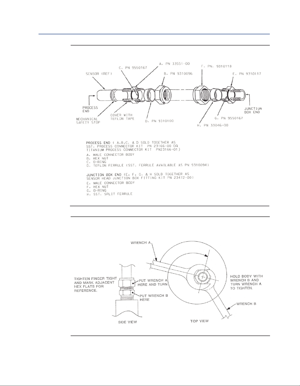
Figure 6-1: Example of Sensor Tube Replacement
Figure 6-2: Male Connector Tightening Diagram
50 Maintenance
Page 57

Instruction Manual Diagnostics and Troubleshooting
LIQ-MAN-396R-396RVP March 2017
Section 7: Diagnostics and Troubleshooting
7.1 Diagnostics and Troubleshooting with Model
54/81/3081 pH/ORP
The Model 54 and 54e transmitters and Models 81 and 3081 pH Transmitters automatically search
for fault conditions that would cause an error in the measured pH value, as does the Model 1054A/B
pH/ORP transmitter to a lesser degree. Refer to the respective manual for a complete description
of the transmitter’s fault conditions.
Table 7-1 lists the transmitters diagnostic messages that indicate a possible sensor problem. A more
complete description of the problem and a suggested remedy corresponding to each message is
also listed.
Table 7-1: Troubleshooting with Diagnostics
Diagnostics and Troubleshooting 51
Page 58

Diagnostics and Troubleshooting Instruction Manual
March 2017 LIQ-MAN-396R-396RVP
Table 7-2: Troubleshooting without Diagnostics
Trouble Probable Cause Remedy
eter reads off scale. (Display
M
reads overrange.)
Display reads between 3 and 6
pH regardless of actual pH of
solution or sample.
Meter or display indication
swings or jumps widely in
AUTO T.C. Mode.
Span between buffers
extremely short in AUTO T.C.
Mode.
Sluggish or slow meter
indication for real changes in
pH level.
efective preamplifier.
D
T.C. element shorted. Check T.C. element as instructed in Section 6.5
Sensor not in process or sample stream is low. Make sure sensor is in process with sufficient
Open glass electrode. Replace sensor.
Reference element open - no contact. Replace sensor.
Electrode cracked. Replace sensor.
T.C. element shorted. Check T.C. element as instructed in Section 6.5
T.C. element open. Check T.C. element as instructed in Section 6.5
Electrode coated. Clean sensor as instructed in Sections 6.3 or
Electrode at end of life. Replace sensor.
eplace preamplifier (for code 02 sensors). For
R
code 01, replace sensor.
and replace sensor if defective.
sample stream (refer to Section 2.0 for
installation details).
and replace sensor if defective.
and replace sensor if defective.
6.4. Replace sensor if cracked.
Transmitter cannot be
standardized.
Transmitter short spans
between two different buffer
values.
Electrode coated or cracked. Clean sensor as instructed in Sections 6.3 or
6.4. Replace sensor if cracked.
Electrode at end of life, due to old glass or high
temperature exposure.
Coated glass. Clean sensor as instructed in Sections 6.3 or
Replace sensor.
6.4. Replace sensor if cracked.
Note: For any repair or warranty inquiries please contact our Customer Care group.
52 Diagnostics and Troubleshooting
Page 59

Instruction Manual Accessories
LIQ-MAN-396R-396RVP March 2017
Section 8: Accessories
8.1 Accessories
Table 8-1: Accessories for Rosemount 396R
Part Number Description
23550-00 Remote Junction box with extension board
9210012 Buffer solution, 4.01 pH, 16 oz
9210013 Buffer solution, 6.86 pH, 16 oz
9210014 Buffer solution, 9.18 pH, 16 oz
23557-00 Preamplifier for junction box for Models 1055, 54e, 81, 3081, 4081, 5081, Xmt
Table 8-2: Accessories for Rosemount 396RVP
Part Number Description
23557-00 Preamplifier for junction box for Models 54e, 81, 3081, 4081, 5081, Xmt, 1055
33046-00 Ferrule, 1 in., split 316SS
9310096 Nut, swage, 1 in. 316SST
9210012 Buffer solution, 4.01 pH, 16 oz
9210013 Buffer solution, 6.86 pH, 16 oz
9210014 Buffer solution, 9.18 pH, 16oz
R508-80Z ORP solution, 460 mv ± 10 at 20°C
Accessories 53
Page 60

Diagnostics and Troubleshooting Instruction Manual
March 2017 LIQ-MAN-396R-396RVP
54 Accessories
Page 61

Instruction Manual EC Declaration of Conformity
LIQ-MAN-396R-396RVP March 2017
EC Declaration of Conformity
Note: Please see website for most recent Declaration.
EC Declaration of Conformity 55
Page 62
Diagnostics and Troubleshooting Instruction Manual
March 2017 LIQ-MAN-396R-396RVP
56 EC Declaration of Conformity
Page 63

ANY FM APPROVED
ASSOCIATED APPARATUS
HAVING ENTITY PARAMETERS
NO
N-
H
AZARDOUS
(UNCLASSIFIED)
AREA
CLASS I, II, III, DIVISION 1, GROUPS A-G
T6 Ta = 60°C
SENSOR
ENTITY PARAMETERS
Ui = 13.1U, Ii = 358mA
Pi = 698 mW
Ci = 0.967 µF, Li = 0.1mH
1. NO REVISION TO THIS DRAWING IS PERMITTED WI THOUT
FM APPROVAL.
2. U
max
> U
t
; I
max
> I
t
; (C
i
OF ALL LOOPS + C CABLE) < C
a
;
(L
i
OF ALL LOOPS + L CABLE) < L
a
, P
max
OR P
i
> P
0.
3. SINGLE MULTI-CHANNEL
IS BARRIER OR APPARATUS MUST BE FM APPROVED,
4. SINGLE MULTI-CHANNEL
IS BARRIER OR APPARATUS MANUFACTURE'S
CONTROL DRAWI NGS MUST BE FOLLOWED WHEN INSTALLING THE SYSTEM.
IS BARRIER OR EQUI PMENT MAY BE INSTALLED WITHIN THE HAZARDOUS
(CLASSIFIED) LOCATION FOR WHICH IT IS APPROVED
.
5. INSTALLATION MUST BE IN ACCORDANCE WITH ARTICL
E 500 OF THE NEC
(ANSI/NFPA 70) AND ANSI/ISA RP 12.6.
WARNING: SUBSTITUTION OF COMPONENTS MAY IMPA
IR INTRINSIC SAFETY.
6. pH & AMPEROMETRIC SENSORS WITHOUT PREAMPS ARE SIMPLE APPARATUS.
ZON E
ZONE 0
7. CONTROL EQUIPMENT CONNECTED TO THE ASSOCIATED APPARATUS MUST
NOT USE OR GENERATE MORE THAN 250V.
RESISTANCE BETWEEN INTRINSICALLY SAFE GROUND AND EARTH GROUND
MUST BE LESS THAN OR EQUAL TO 1 OHM.
ANY
FM APPROVED TRANSMITTER FOR
DIVISION 1 WI TH INTRINSICALLY SAFE
OUTPUT PARAMETERS. THIS
FM
APPROVED DEVICE MUST BE INSTALLED
PER ITS INSTALLATION DRAWING.
FM
APPROVED EQUIPMENT (MAY BE
MULTIPLE DEVICES, NUMBER IS LIMITED
BY REQUIREMENTS TO MEET ALL OTHER
IS REQUIREMENTS FOR THE NETWORK)
WITH EQUIVALENT HAZARDOUS AREA
APPROVALS.
H
AZA RDOUS
(CL ASSI
F
IED)
AREA
INTRISICALLY SA FE
9. pH/ORP SENSOR MODELS THAT MAY CONTAIN THE PREAMPLIFIER:
3900/VP
3500/VP
3300HT/VP
3400HT/VP
396/VP
396R/VP
396P/VP
398R/VP
399/VP
389/VP
385/385+
10. WARNING: TO PREVENT IGNITION OF FLAMMABLE OR COMBUSTIBLE
ATM OSPHERES, DISCONNECT POWER BEFORE SERVIC
ING.
11. THE ENTI TY CONCEPT ALLOWS INTECONNECTION OF INTRINSICALLY SAFE
APPARATUS WITH ASSOCIATED APPARATUS WHEN THE FOLLOWING IS TRUE:
U
i
> U
o;
I
i
> I
o;
P
i
> P
o;
C
o
> C
i
+ C CABLE; L
o
> L
i
+ L CABLE.
12. COPY REVI SIONS TO 1400332 TO pH/ORP SHIPPING MANUALS.
13 Ci INCLUDES THE CAPACITANCE OF 500 FEET OF SENSOR CABLE.
13
DWG NO.
1400332
8.
Instruction Manual FM Installation
LIQ-MAN-396R-396RVP March 2017
Intrisicallly Safe Sensor Installation Drawing - FM
FM Installation 57
Page 64

LIQ-MAN-396R-396RVP
Rev. K
March 2017
www.Emerson.com/RosemountLiquidAnalysis
Youtube.com/user/Rosemount
Twitter.com/Rosemount_News
Emerson
8200 Market Blvd.
Chanhassen, MN 55317,
USA
Tel +1 800 999 9307
Fax +1 952 949 7001
Liquid.CSC@Emerson.com
Analyticexpert.com
facebook.com/Rosemount
©2017 Emerson. All rights reserved.
The Emerson logo is a trademark and service mark of Emerson Electric Co. Rosemount is a mark of
one of the Emerson family of companies. All other marks are the property of their respective
owners.
The contents of this publication are presented for information purposes only, and while effort has
been made to ensure their accuracy, they are not to be construed as warranties or guarantees,
express or implied, regarding the products or services described herein or their use or applicability.
All sales are governed by our terms and conditions, which are available on request. We reserve the
right to modify or improve the designs or specifications of our products at any time without notice.
 Loading...