

Page 1
Rosemount 396P/396PVP
pH/ORP Sensors
Instruction Manual
IQ-MAN-396P-396PVP
L
Rev. E
March 2017
Page 2

asgkas
h
Page 3

Essential Instructions
Read this page before proceeding
Emerson designs, manufactures and tests its products to meet many national and international stan-
dards. Because these sensors are sophisticated technical products, you MUST properly install, use,
nd maintain them to ensure they continue to operate within their normal specifications. The
a
following instructions MUST be adhered to and integrated into your safety program when installing,
using, and maintaining Rosemount products. Failure to follow the proper instructions may cause
any one of the following situations to occur: Loss of life; personal injury; property damage; damage
to this sensor; and warranty invalidation.
• Read all instructions prior to installing, operating, and servicing the product.
• If you do not understand any of the instructions, contact your Emerson representative for clarification.
• Follow all warnings, cautions, and instructions marked on and supplied with the product.
• Inform and educate your personnel in the proper installation, operation, and maintenance of the
product.
• Install your equipment as specified in the Installation Instructions of the appropriate Instruction Manual and per applicable local and national codes. Connect all products to the proper electrical and pressure sources.
• To ensure proper performance, use qualified personnel to install, operate, update, program,
and maintain the product.
• When replacement parts are required, ensure that qualified people use replacement parts specified by Emerson. Unauthorized parts and procedures can affect the product's performance,
place the safe operation of your process at risk, and VOID YOUR WARRANTY. Third-party substitutions may result in fire, electrical hazards, or improper operation.
• Ensure that all equipment doors are closed and protective covers are in place, except when maintenance is being performed by qualified persons, to prevent electrical shock and personal injury.
The information contained in this document is subject to change without notice.
DANGER
Hazardous Area InstallationN
Installations near flammable liquids or in hazardous area locations must be carefully evaluated by
qualified on site safety personnel.
To secure and maintain an intrinsically safe installation, the certified safety barrier, transmitter, and
sensor combination must be used. The installation system must comply with the governing approval
agency (FM, CSA or BASEEFA/CENELEC) hazardous area classification requirements. Consult your
transmitter instruction manual for more details.
Proper installation, operation and servicing of this sensor in a Hazardous Area Installation is entirely
the responsibility of the user.
CAUTION
Sensor/Process Application Compatibility
The wetted sensor materials may not be compatible with process composition and operating
conditions. Application compatibility is entirely the responsibility of the user.
CAUTION
Special Conditions for Safe Use
1. All pH/ORP sensors have a plastic enclosure which must only be cleaned with a damp cloth to avoid
the danger due to a build up of an electrostatic charge.
2. All pH/ORP sensor models are intended to be in contact with the process fluid and may not meet the
500V r.m.s. a.c. test to earth.
This must be taken into consideration at installation.
Page 4

About This Document
This manual contains instructions for installation and operation of the Rosemount 396P/396PVP
pH/ORP Sensors. The following list provides s concerning all revisions of this document.
Rev. Level Date Notes
A 02/2013 Manual updated with SMART sensor information.
B 08/2013 Wiring diagrams updated.
C 12/2014 Included new EC Declaration.
D 07/2016 Added EC Declaration of Conformity, Added FM Installation
Drawing, Added Hazardous Location Approvals,
Updated Ordering Information.
E 03/2017 Updated Ordering Information, Address and Emerson logo.
Page 5

Instruction Manual Table of Contents
LIQ-MAN-396P-396PVP March 2017
Contents
Section 1: Description and Specifications
1.1 Features and Applications....................................................................................1
1.2 Product Certifications .........................................................................................2
1.3 Ordering Information...........................................................................................3
Section 2: Installation
2.1 Unpacking and Inspection ...................................................................................7
2.2 Mounting.............................................................................................................7
Section 3: Wiring
3.1 General .............................................................................................................13
Section 4: Start-Up and Calibration
4.1 Rosemount 396P and 396PVP pH Sensors..........................................................35
4.2 Rosemount 396P and 396PVP ORP Sensors........................................................36
Section 5: Maintenance
5.1 General Information...........................................................................................37
5.2 Automatic Temperature Compensator...............................................................37
5.3 Rosemount 396P and 396PVP pH Sensors..........................................................37
5.4 Rosemount 396P and 396PVP ORP Sensors........................................................38
Section 6: Diagnostics and Troubleshooting
6.1 56/1056/1057/1066/54e/81/3081/4081/5081/Xmt
Diagnostics and Troubleshooting .......................................................................41
6.2 Troubleshooting without Advanced Diagnostics ................................................42
EC Declaration of Conformity.............................................................................44
Intrisicallly Safe Sensor Installation - FM.....................................................46
Section 7: Return of Material
7.1 General..............................................................................................................47
Table of Contents i
Page 6

Table of Contents Instruction Manual
March 2017 LIQ-MAN-396P-396PVP
ii Table of Contents
Page 7

Instruction Manual Section 1: Description and Specifications
LIQ-MAN-396P-396PVP March 2017
Section 1: Description and Specifications
1.1 Specifications - General
Measurements and Ranges: pH*: 0-14 / ORP: -1500 to 1500 mv
Available pH ACCUGLASS Types: GPLR hemi or flat glass
Wetted Materials: Titanium, Polypropylene, EPDM, glass; platinum (ORP only)
Process Connection: 1 in. MNPT front and rear facing threads
Temperature Range: 0-100°C (32-212°F)
Pressure Range-Hemi bulb: 100-1135 kPa [abs] (0-150 psig)
Pressure Range-Flat bulb: 100-790 kPa [abs] (0-100 psig)
Minimum Conductivity: 100 µS/cm
Integral Cable 396P: Code 01 - 25 ft; Code 02 - 15 ft coaxial / 396PVP: none - must use mating
VP cable
Weight/Shipping Weight: 0.45 kg/0.9 kg (1 lb/2 lb)
*Percent Linearity
pH Range 396 / 396VP 396P / 396PVP 396R / 396RVP
GPHT Hemi GPHT Flat GPHT Hemi GPLR Flat GPHT Hemi GPHT Flat
0-2 pH 94% 95% 94% – 94% 93%
2-12 pH 99% 99% 97% 98% 97% 98%
12-13 pH 97% 96% 98% 95% 98% 95%
13-14 pH 92% – 98% – 98% –
Description and Specifications 1
Page 8

Section 1: Description and Specifications Instruction Manual
March 2017 LIQ-MAN-396P-396PVP
1.2 Product Certifications
See online certificates for more details
ee online certificates for more details.
IECEx
Sensors without preamp (pH and ORP) – Ex ia IIC T4 Ga (-20 °C ≤ Ta ≤ +60 °C)
Sensors with SMART preamp (pH only) – Ex ia IIC T4 Ga (-20 °C ≤ Ta ≤ +60 °C)
Sensors with standard preamp (396P only) – Ex ia IIC T4 Ga (-20 °C ≤ Ta ≤ +80 °C) or
Ex ia IIC T5 Ga (-20 °C ≤ Ta ≤ +40 °C)
Per standards IEC60079-0 : 2011, IEC 60079-11 : 2011
ATEX
Sensors without preamp (pH and ORP) – II 1 G Ex ia IIC T4 Ga (-20 °C ≤ Ta ≤ +60 °C)
Sensors with SMART preamp (pH only) – II 1 G Ex ia IIC T4 Ga (-20 °C≤ Ta ≤ +60 °C)
Sensors with standard preamp (396P only) – II 1 G Ex ia IIC T4 Ga (-20 °C ≤ Ta ≤ +80 °C) or
II 1 G Ex ia IIC T5 Ga (-20 °C ≤ Ta ≤ +40 °C)
S
Per standards EN 60079-0: 2012+A11:2013, EN 60079-11:2012
FM
Intrinsically Safe for use in Class I, II, and III, Division 1, Groups A, B, C, D, E, F, and G;
Temperature Class T6 Ta = -20 °C to +60 °C
Intrinsically Safe for use in Class I, Zone 0, AEx ia IIC T6 Ta = -20 °C to +60 °C
Nonincendive for use in Class I, Division 2, Groups A, B, C, and D;
Temperature Class T6 Ta = -20 °C to +60 °C
Suitable for use in Class II and III, Division 2, Groups E, F, and G;
Temperature Class T6 Ta = -20 °C to +60 °C Hazardous (Classified) Locations
IS/I,II,III/1/ABCDEFG/T6 Ta = 60 °C - 1400332; Entity; I/0/AEx ia IIC/T6 Ta = 60 °C - 1400332;
Entity; NI/I/2/ABCD/T6 Ta = 60 °C; S/II,III/2/EFG/T6 Ta = 60 °C
Per standards 3600:1998, 3610:2010, 3611:2004, 3810:2005
CSA
Sensors with preamp – Intrinsically Safe:
Class I, Division 1, Groups ABCD; Class II, Division 1, Groups EFG; Class III; Class I, Division 2,
Groups ABCD; Ambient temperature rating -20˚C to +60 °C; Ex ia IIC; T6
Sensors without preamp – Intrinsically Safe and Non-Incendive:
See online FM Certificate of Compliance for applicable sensor options.
See online CSA Certificate of Compliance for applicable sensor options.
Class I, Division 1, Groups ABCD; Class II, Division 1, Groups EFG; Class III; Class I, Division 2,
Groups ABCD; Ex ia IIC; T6; Ambient temperature rating -20 °C to +60 °C: (Simple Apparatus)
Per standards C22.2 No. 0-10, C22.2 No. 0.4-M2004, C22.2 No. 94-M1991, C22.2 No. 142 –
M198, C22.2 No 157 – M1992, CAN/CSA E60079-0:0, CAN/CSA E60079-11:02, UL50 11th Ed,
UL508 17th Ed, UL913 7th Ed, UL 60079-0: 2005, UL 60079-11: 2002
2 Description and Specifications
Page 9
Instruction Manual Section 1: Description and Specifications
LIQ-MAN-396P-396PVP March 2017
1.3 Ordering Information
The Rosemount 396P Sensor is housed in a molded
reinforced polypropylene body with 1 in. MNPT threads
suitable for insertion, submersion or flow through
installation. The sensor includes a general purpose pH
electrode or a platinum ORP electrode, a reference junction and a solution ground. The Rosemount 396P comes
standard with a recessed electrode; an optional slotted
tip is also available. In addition, the Rosemount 396P
features an optional integral hermetically sealed preamplifier and 15 ft or 25 ft cable lengths. Automatic temperature compensation, Pt 100 or 3K Balco, is standard with
the Rosemount 396P.
The Rosemount 396PVP Sensor has similar features to
the Rosemount 396P. However, the Rosemount 396PVP
is offered with the Variopol (VP) connector and uses a
mating VP cable (purchased separately).
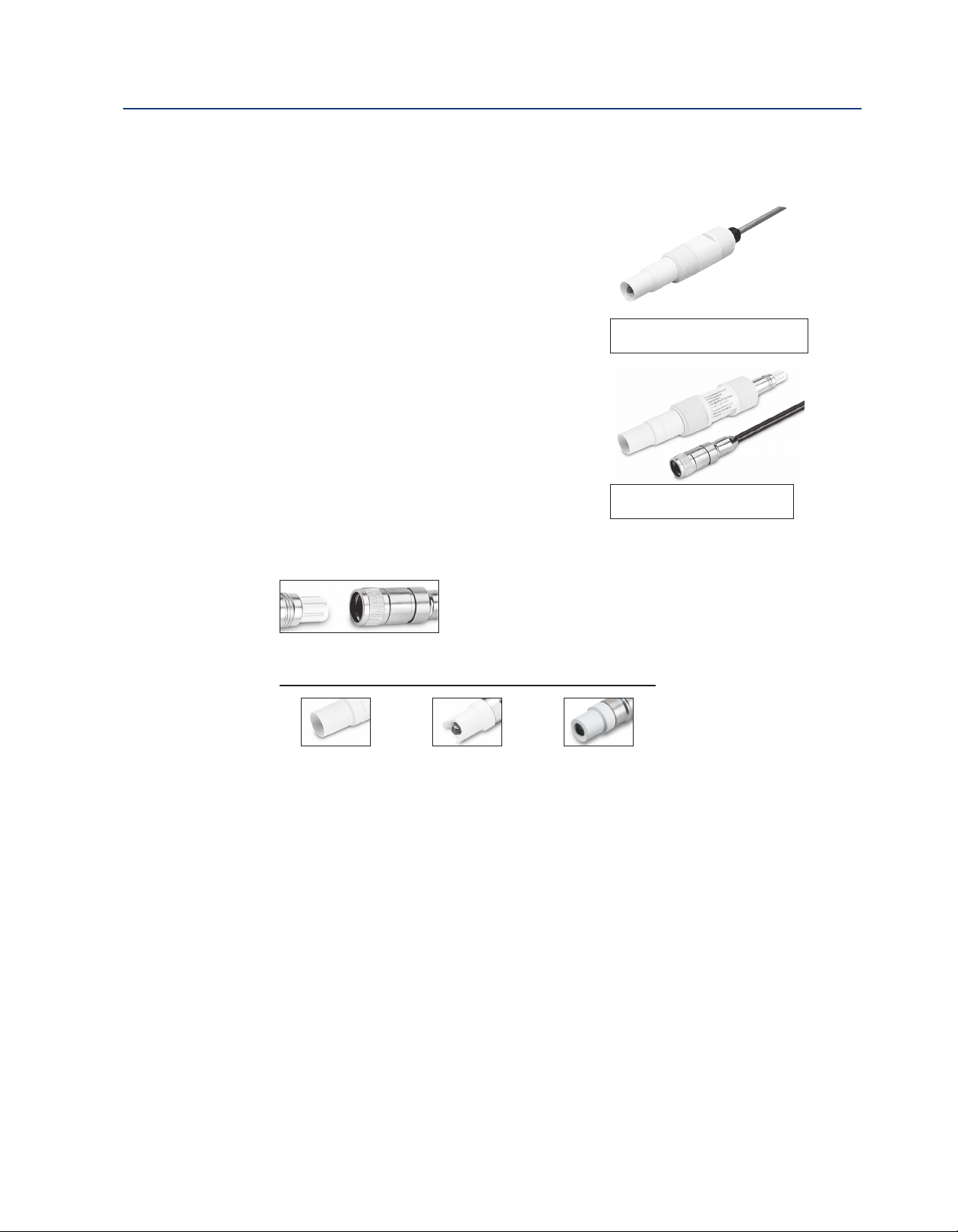
Rosemount 396P with Integral Cable
Connection
Rosemount 396PVP with Variopol
Cable Connection
Examples of all sensing tip offerings
Shrouded Tip is
standard on all
hemi bulb sensors
A Variopol cable is required for all new installations. See below
for cable selection.
Variopol connector shown with
mating variopol cable receptacle
Optional Slotted Tip
available on all hemi
bulb sensors, ordered
as option -41
is
Flat Tip is available
with flat glass bulb
sensors
Description and Specifications 3
Page 10

Section 1: Description and Specifications Instruction Manual
March 2017 LIQ-MAN-396P-396PVP
Table 1-1. Rosemount 396P Ordering Information
Model Sensor Type
96P
3
Preamplifier/Cable
01 With Integral Preamplifier and 25 ft (7.6m) Cable
02 Without Integral Preampflier and 15 ft (4.6m) Cable
Measuring Electrode Type
10 pH - GPLR Glass
12 ORP
13 pH - GPLR Flat Glass
Transmitter/TC Compatibility
50 For 1181 (3K TC)
54 For 1054A/B, 2054 2081 (Pt-100)
55 For 54, 1055, 1056, 1057, 6081, 3081, 4081, 5081, XMT, 56 (Pt-100)
Optional Tip Offerings
_ No Selection
41 Slotted Tip
Typical Model Number: 396P-01-10-55
H/ORP Sensor
p
1)
(
1. Not available with option 13.
Table 1-1. Rosemount 396P Ordering Information
Model Sensor Type
396PVP pH/ORP Sensor
Measuring Electrode Type
10 pH - GPLR Glass
12 ORP
13 pH - GPLR Flat Glass
Transmitter/TC Compatibility
50 For 1181 (3K TC)
54 For 1054A/B, 2054 2081 (Pt-100)
55 For 54, 1055, 1056, 1057, 6081, 3081, 4081, 5081, XMT, 56 (Pt-100)
Optional Tip Offerings
_ No Selection
41 Slotted Tip
(1)
Preamplifier Option
_ No Preamplifier
70 SMART Preamplifier
(2)
Typical Model Number: 396PVP-10-55-_-70
1. Not available with option 13.
2. Only available with pH sensors and option 55.
4 Description and Specification
Page 11

Instruction Manual Section 1: Description and Specifications
LIQ-MAN-396P-396PVP March 2017
Accessories
Table 1-3. Accessories Information
Connector cable, VP8 (required for all first time installations of VP sensors)
24281-00 15 ft. (4.6m) VP8 cable
24281-01 25 ft. (7.6m) VP8 cable
24281-03 50ft (15.2m) VP8 Cable
24281-04 100ft (30.5m) VP8 Cable
24281-06 10ft (3.0m) VP8 Cable
24281-07 20ft (6.1m) VP8 Cable
24281-08 30ft (9.1m) VP8 Cable
Remote Junction Boxes and Mounting Brackets; for use when standard cable lengths need to be extended
23555-00
23550-00
2002565
Extension Cables (required when using a remote junction box)
23646-01
9200273
Calibration Accessories
9210012 Buffer Solution, pH 4.01, 16 oz (473 ml)
9210013 Buffer Solution, pH 6.86, 16 oz (473 ml)
9210014 Buffer Solution, pH 9.18, 16 oz (473 ml)
R508-8OZ ORP Standard, 475mV, 8oz (236 ml)
Mounting Assemblies
11275-01
2002011 CPVC flow through Tee, 1-1/2 in. NPT process connections
Junction Box; contains preamplifier for 54e, 56, 1055, 1056, 1057, 1066, 3081, 4081, 5081,
6081, XMT
Junction Box with board for point-to-point cable extension; use with sensors containing integral preamplifiers
Mounting Bracket Kit with mounting plate and U-bolts; use with PN 23555-00 or 23550-00
junction boxes
Extension Cable, 11-conduit with shields, wires prepared for easy installation, per foot (or
meter); best choice for easiest installation
Extension Cable, 11-conduit with shield, raw cable (user must cut and prepare cable ends),
per foot (or meter)
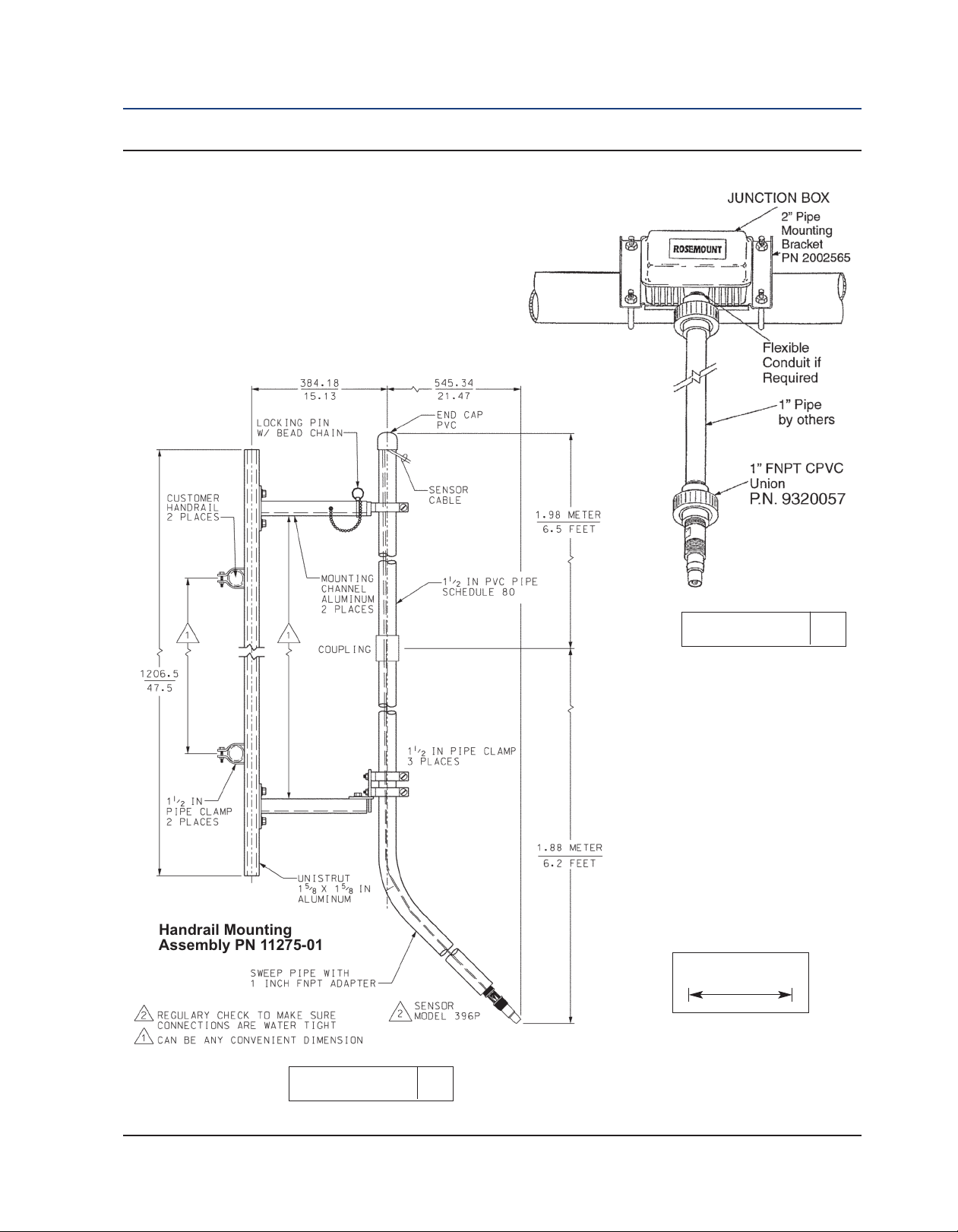
Handrail Mounting Assembly; includes a 6 ft straight pipe, pipe coupling, 6 ft long sweep
pipe, unistrut, pipe clamps, and mounting channels
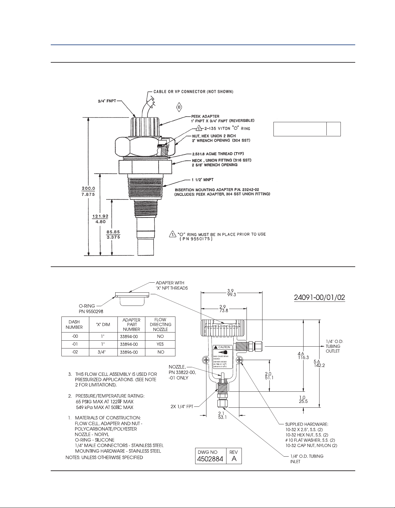
24091-00 Low Flow Cell with 1/4 in. inlet and outlet
915240-03
915240-04
915240-05
12707-00 Jet Spray Cleaner; for use with water or air cleaning using interval timer from instrument
Description and Specifications 5
Tee, Flow-through, 2 in. PVC tee with ¾ in. NPT process connections and mounting adapter
to eliminate cable twisting
Tee, Flow-through, 2 in. PVC tee with 1 in. NPT process conections and mounting adapter to
eliminate cable twisting
Tee, Flow-through, 2 in. PVC tee with 1½ in. NPT process connections and mounting adapter
to eliminate cable twisting
Page 12

Section 1: Description and Specifications Instruction Manual
March 2017 LIQ-MAN-396P-396PVP
6 Description and Specifications
Page 13

Instruction Manual Section 2: Installation
LIQ-MAN-396P-396PVP March 2017
Section 2: Installation
2.1 Unpacking and Inspection
Inspect the outside of the carton for any damage. If damage is detected, contact the carrier
immediately. Inspect the hardware. Make sure all the items in the packing list are present and in
good condition. Notify the factory if any part is missing. If the sensor appears to be in satisfactory condition, proceed to Section 2.2, Mounting.
NOTE: Save the original packing cartons and materials as most carriers require proof of damage
due to mishandling, etc. Also, if it is necessary to return the sensor to the factory, you must
pack the sensor in the same manner as it was received. Refer to Section 6.0 for return instructions. If the sensor is to be stored, the vinyl boot should be filled with pH buffer solution and
replaced on sensor tip until ready to use.
CAUTION
Buffer solution, in the vinyl boot, may cause skin or eye irritation.
WARNING
Glass electrode must be wetted at all times (in storage and in line) to maximize sensor life.
2.2 Mounting
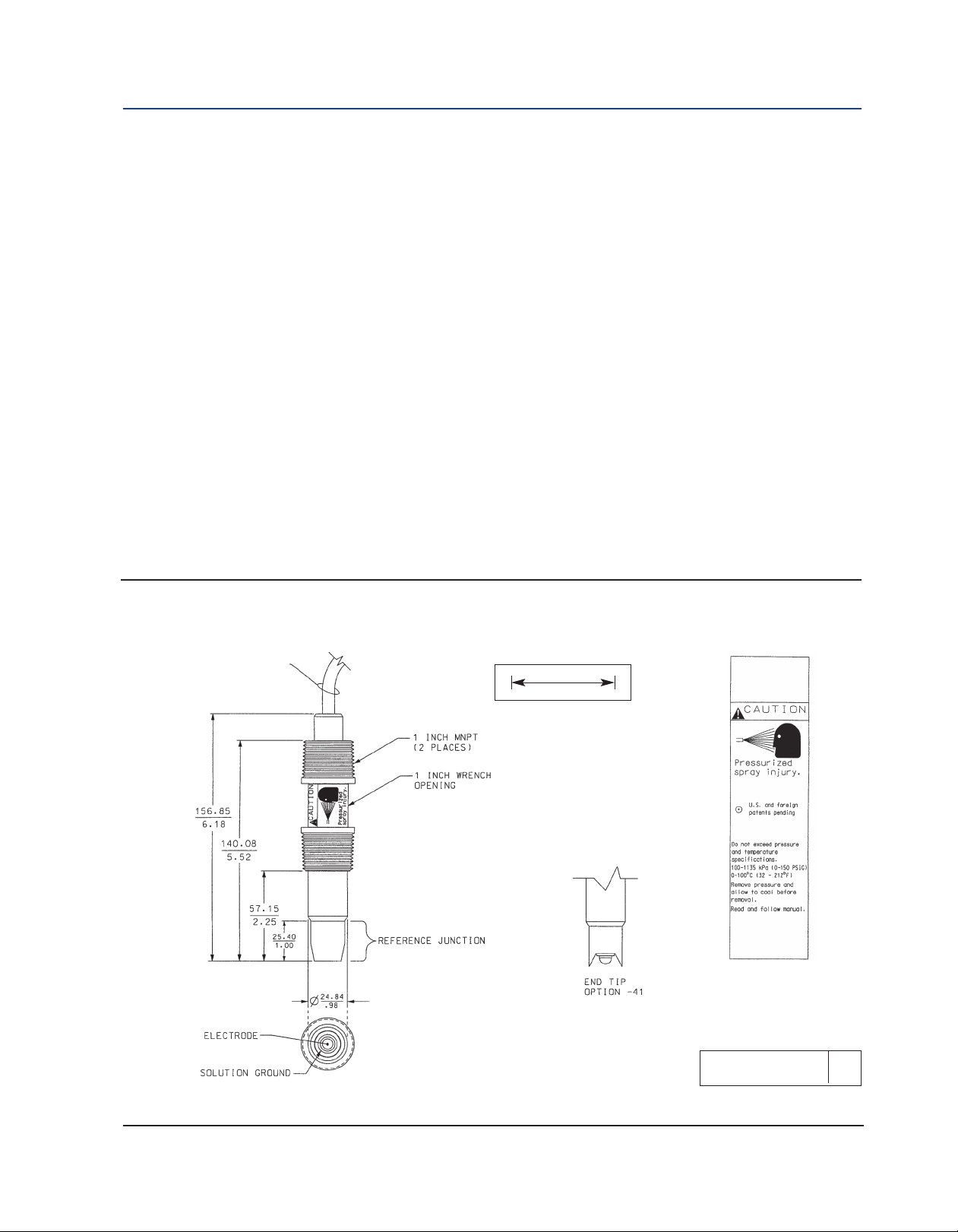
The sensor has been designed to be located in industrial process environments. Temperature
and pressure limitations must not be exceeded at any time. A caution label regarding this
matter is attached to the sensor. Please do not remove the label. See Figure 2-1.
CAUTION
Internal electrolyte fill solution may cause skin or eye irritation.
Mounting Guidelines:
1. Shake the sensor in a downward motion to remove any air bubbles that may be present
inside the tip of the pH glass.
2. Do not install the sensor on the horizontal. The sensor must be 10° off the horizontal to
ensure accuracy.
3. Do not install the sensor upside down.
4. Air bubbles may become trapped in the sensor end between the glass bulb and the sensor
body. This problem is most commonly encountered in areas of low flow or during calibration.
Shake the probe while immersed in solution to remove bubbles. This problem can be
avoided by ordering the sensor with the slotted tip (option 41).
In most cases, the pH sensor can simply be installed as shipped and readings with an accuracy
of ± 0.6 pH may be obtained. To obtain greater accuracy or to verify proper operation, the
sensor must be calibrated as a loop with its compatible analyzer or transmitter.
Installation 7
Page 14
Section 2: Installation Instruction Manual
March 2017 LIQ-MAN-396P-396PVP
2.2.1 Flow Through and Insertion Mounting
osemount 396P and 396PVP Sensors have a 1-inch MNPT process connection at the front of
R
the sensor for mounting into a 1-1/2 inch tee or the process pipes. See Figure 2-2 through
Figure 2-7 for instal lation configurations.
NOTE: LARGE PIPE WRENCHES MUST NOT BE USED TO TIGHTEN THE SENSOR INTO A FLANGE
OR OTHER TYPE OF MOUNTING.
2.2.2 Submersion Mounting
Rosemount 396P and 396PVP Sensors also have a 1 inch MNPT process connection at the back
of the sensor. Utilizing a standard 1 inch union, the sensor may be mounted to a 1 inch SCH 80
CPVC or PVDF standpipe. Tapered pipe threads in plastic tend to loosen after installation. It is
therefore recom mended that Teflon1 tape be used on the threads and that the tightness of the
connection be checked frequently to assure that no loosening has occurred. To prevent rain
water or condensation from running into the sensor, a weatherproof junction box is recommended. The sensor cable must be run through a protective conduit for isolation from electrical interference or physical abuse from the process. The sensor should be installed within 80°
of vertical, with the electrode facing down. The sensor’s cable should not be run with power or
control wiring.
Figure 2-1. Dimensional Drawing
SENSOR CABLE
(OR VP CONNECTOR
- NOT SHOWN)
MILLIMETER
INCH
DWG. NO. REV.
40396P01 D
8 Installation
Page 15
Sensors Instruction Manual Section 2: Installation
LIQ-MAN-396P-396PVP March 2017
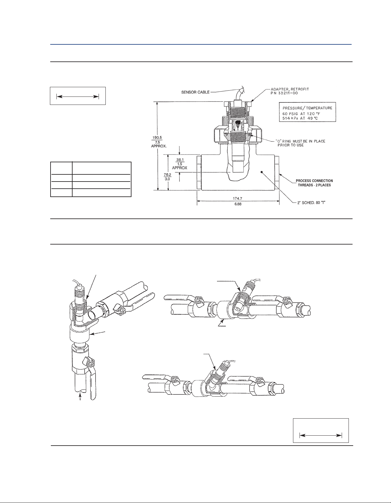
igure 2-2. Flow-Through Tee with Adapter (PN 915240-xx*)
F
MILLIMETER
NCH
I
xx* Process Connection
03 3/4 inch
04 1 inch
05 1-1/2 inch
Threads
Figure 2-3. Flow-Through and Insertion Installations
1-1/2” X 1”
Reducing
Bushing
1-1/2” X 1”
Reducing
1-1/2” Pipe Tee
PN 2002011
1-1/2” X 1”
ANGLE
FLOW
Reducing
Bushing
SHOWN
Bushing
STRAIGHT
FLOW
SHOWN
1-1/2” Pipe Tee
PN 2002011
PIPE “Y”
INSTALLATION
SHOWN
FLOW
Installation 9
1-1/2” PIPE “Y”
WHEN INCH AND METRIC DIMS
ARE GIVEN
MILLIMETER
INCH
Page 16
Section 2: Installation Instruction Manual
March 2017 LIQ-MAN-396P-396PVP
Figure 2-4. Rosemount 396P with Insertion Mounting Adapter (PN 23242-02). Not for use with Rosemount
96PVP. Mounting adapter allows for sensor removal without twisting or disconnecting interconnecting cable
3
for ease of maintenance.
DWG. NO. REV.
40396P02 A
Figure 2-5. Low flow cell PN 24091-00
10 Installation
Page 17
Instruction Manual Section 2: Installation
LIQ-MAN-396P-396PVP March 2017
Figure 2-6. Submersion Installations
Handrail Mounting
Assembly PN 11275-01
DWG. NO. REV.
40396P03 A
WHEN INCH AND METRIC DIMS
ARE GIVEN
MILLIMETER
INCH
DWG. NO. REV.
40396P04 A
Installation 11
Page 18

Section 2: Installation Instruction Manual
March 2017 LIQ-MAN-396P-396PVP
Figure 2-7. Jet Spray Cleaner PN 12707-00
12 Installation
Page 19

Instruction Manual Section 3: Wiring
LIQ-MAN-396P-396PVP March 2017
Section 3: Wiring
3.1 General
Figures in this section provide guidelines for wiring the Rosemount 396P/396PVP sensor to
various transmitters.
To determine which wiring guideline to use, locate the model number of the sensor to be
installed.
1. If the cable needs to be extended, use a high quality eleven conductor double shielded
instrument cable available from Rosemount. Refer to Table 3-1 for the appropriate junction
box to use and the corresponding wiring details.
NOTE: If the cable is too long, loop up the excess cable. If the cable has to be shortened, cut and
terminate each conductor neatly and make sure that the overall (outermost) drain wire is not
shorted out with either of the two inner drain wires (shields).
2. Signal cable should be run in a dedicated conduit (preferably an earth grounded metallic
conduit) and should be kept away from AC power lines. For your convenience, a wire nut kit is
furnished (in a plastic bag wrapped around the cable).
NOTE: For maximum EMI/RFI protection when wiring from the sensor to the junction box, the
outer braid of the sensor should be connected to the outer braided shield of the extension
cable. The outer braid of the extension cable to the instrument must be terminated at earth
ground or by using an appropriate metal cable gland fitting that provides a secure connection
to the instrument cable.
Wiring
The Rosemount 396P and 396PVP has an optional built-in preamplifier and is offered with a
shielded cable. The cable should be handled carefully and kept dry and free of corrosive chemicals at all times. Extreme care should be used to prevent it from being twisted, damaged or
scraped by rough, sharp edges or surfaces.
DANGER
DO NOT CONNECT SENSOR CABLE TO POWER LINES. SERIOUS INJURY MAY RESULT.
NOTE: Remove electrical tape or shrink sleeve from gray reference wire before connecting wire
to terminal.
Wiring 13
Page 20

Section 3: Wiring Instruction Manual
March 2017 LIQ-MAN-396P-396PVP
NOTE
For additional wiring information on this product, including sensor combinations not shown here, please refer to our
website Wiring Diagrams.
Figure 3-1. Wiring for 396P-01 (Gray Cable)
and 54e pH/ORP
Figure 3-3. Wiring for 396P-02 (Gray Cable)
and 54e pH/ORP
Figure 3-2. Wiring for 396P-01 (Blue Cable) and 54e
pH/ORP
Figure 3-4. Wiring for 396P-02 (Blue Cable) and 54e
pH/ORP
14 Wiring
Page 21

Instruction Manual Section 3: Wiring
LIQ-MAN-396P-396PVP March 2017
Figure 3-5. Wiring for 396PVP (Gray Cable)
and 54e pH/ORP
Figure 3-6. Wiring for 396PVP (Blue Cable) and 54e
pH/ORP
Figure 3-7. Wiring for 396P-01 and 1055
Wiring 15
Page 22

Section 3: Wiring Instruction Manual
March 2017 LIQ-MAN-396P-396PVP
Figure 3-8. Wiring for 396P-02 and 1055
Figure 3-9. Wiring for 396PVP and 1055
Figure 3-10. Wiring for Dual 396P-01 and 1055
16 Wiring
Page 23

Instruction Manual Section 3: Wiring
LIQ-MAN-396P-396PVP March 2017
Figure 3-11. Wiring for Dual 396P-02 and 1055
Figure 3-12. Wiring for Dual 396PVP and 1055
Wiring 17
Page 24

Section 3: Wiring Instruction Manual
March 2017 LIQ-MAN-396P-396PVP
Figure 3-13. Wiring for 396P-01 (Gray Cable) and
1056/56
Figure 3-14. Wiring for 396P-01 (Blue Cable) and
1056/56
Figure 3-15. Wiring for 396P-02 (Gray Cable) and
1056/56
Figure 3-16. Wiring for 396P-02 (Blue Cable) and
1056/56
18 Wiring
Page 25

Instruction Manual Section 3: Wiring
LIQ-MAN-396P-396PVP March 2017
Figure 3-17. Wiring for 396PVP (Gray Cable) and
1056/56
Figure 3-18. Wiring for 396P-01 (Blue Cable) and
1056/56
Figure 3-19. Wiring for 396VP-70 (Blue Cable) and 1056/1057/56
Wiring 19
Page 26

Section 3: Wiring Instruction Manual
March 2017 LIQ-MAN-396P-396PVP
Figure 3-20. Wiring for 396P-01 (Gray Cable) and
1057
Figure 3-21. Wiring for 396P-01 (Blue Cable) and
1057
Figure 3-22. Wiring for 396P-02 (Gray Cable) and
1057
Figure 3-23. Wiring for 396P-02 (Blue Cable) and
1057
20 Wiring
Page 27

Instruction Manual Section 3: Wiring
LIQ-MAN-396P-396PVP March 2017
Figure 3-24. Wiring for 396PVP (Gray Cable) and
1057
Figure 3-25. Wiring for 396PVP (Blue Cable) and
1057
Figure 3-26. Wiring for 396P-01 and 1066
Wiring 21
Page 28

Section 3: Wiring Instruction Manual
March 2017 LIQ-MAN-396P-396PVP
Figure 3-27. Wiring for 396P-01 (Blue Cable) and 1066
Figure 3-28. Wiring for 396P-02 and 1066
22 Wiring
Page 29

Instruction Manual Section 3: Wiring
LIQ-MAN-396P-396PVP March 2017
Figure 3-29. Wiring for 396P-02 (Blue Cable) and 1066
Figure 3-30. Wiring for 396PVP and 1066
Wiring 23
Page 30

Section 3: Wiring Instruction Manual
March 2017 LIQ-MAN-396P-396PVP
Figure 3-31. Wiring for 396PVP (Blue Cable) and 1066
Figure 3-32. Wiring for 396PVP-70 (Blue Cable) and 1066
24 Wiring
Page 31

Instruction Manual Section 3: Wiring
LIQ-MAN-396P-396PVP March 2017
Figure 3-33. Wiring for 396P-01 (Gray Cable) and
5081-P-HT
Figure 3-34. Wiring for 396P-01 (Blue Cable) and
5081-P-HT
Figure 3-35. Wiring for 396P-02 (Gray Cable) and
5081-P-HT
Figure 3-36. Wiring for 396P-02 (Blue Cable) and
5081-P-HT
Wiring 25
Page 32

Section 3: Wiring Instruction Manual
March 2017 LIQ-MAN-396P-396PVP
Figure 3-37. Wiring for 396PVP (Gray Cable) and
5081-P-HT
Figure 3-38. Wiring for 396PVP (Blue Cable) and
5081-P-HT
Figure 3-39. Wiring for 396PVP-70 (Gray Cable)
and 5081
Figure 3-40. Wiring for 396PVP-70 (Gray Cable)
and 6081
26 Wiring
Page 33

Instruction Manual Section 3: Wiring
LIQ-MAN-396P-396PVP March 2017
Figure 3-41. Wiring for 396P-01 (Gray Cable) and 6081
Figure 3-42. Wiring for 396P-01 (Gray Cable) and 6081
Wiring 27
Page 34

Section 3: Wiring Instruction Manual
March 2017 LIQ-MAN-396P-396PVP
Figure 3-43. Wiring for 396P-02 (Gray Cable) and 6081
Figure 3-44. Wiring for 396P-02 (Blue Cable) and 6081
28 Wiring
Page 35

Instruction Manual Section 3: Wiring
LIQ-MAN-396P-396PVP March 2017
Figure 3-45. Wiring for 396PVP (Gray Cable) and 6081
Figure 3-46. Wiring for 396PVP (Blue Cable) and 6081
Wiring 29
Page 36

Section 3: Wiring Instruction Manual
March 2017 LIQ-MAN-396P-396PVP
Figure 3-47. Wiring for 396P-01 (Gray Cable)
and Xmt
Figure 3-48. Wiring for 396P-01 (Blue Cable)
and Xmt
Figure 3-49. Wiring for 396P-02 (Gray Cable)
and Xmt
Figure 3-50. Wiring for 396P-02 (Blue Cable)
and Xmt
30 Wiring
Page 37

Instruction Manual Section 3: Wiring
LIQ-MAN-396P-396PVP March 2017
Figure 3-51. Wiring for 396PVP (Gray Cable)
and Xmt
Figure 3-52. Wiring for 396PVP (Blue Cable)
and Xmt
Figure 3-53. Wiring Details for 396PVP or 396P-02-55
with Mating Variopol Cable for use with 81
Figure 3-54. Wiring Details for 396PVP or 396P-02-50
with Mating Variopol Cable for use with 1181
Wiring 31
Page 38

Section 3: Wiring Instruction Manual
March 2017 LIQ-MAN-396P-396PVP
Figure 3-55. Wiring Details for 396PVP or 396P-02-54
with Mating Variopol Cable for use with 2081
Figure 3-56. Wiring Details for 396PVP or 396P-02-55
with Mating Variopol Cable for use with Remote
Junction Box (PN 23555-00) to 81
Figure 3-57. Wiring Details for 396PVP or 396P-02-50
with Mating Variopol Cable for use with Remote
Junction Box (PN 23309-03) to 1181
32 Wiring
Page 39

Instruction Manual Section 3: Wiring
LIQ-MAN-396P-396PVP March 2017
igure 3-58. Wiring Details for 396PVP or 396P-02-54
F
with Mating Variopol Cable for use with 1054A/B &
2054
Figure 3-59. Wiring Details for 396PVP or 396P-02-54
with Mating Variopol Cable for use with 1054
Wiring 33
Page 40

Section 3: Wiring Instruction Manual
March 2017 LIQ-MAN-396P-396PVP
34 Wiring
Page 41

Instruction Manual Section 4: Start-Up & Calibration
LIQ-MAN-396P-396PVP March 2017
Section 4: Start-Up and Calibration
4.1 Rosemount 396P and 396PVP pH Sensors
4.1.1 Sensor preparation
Shake down the sensor to remove any air bubbles that may be present at the tip of the pH glass
bulb. In most cases, the pH sensor can simply be installed as shipped and readings with an accuracy of ± 0.6 pH may be obtained. To obtain greater accuracy or to verify proper operation, the
sensor must be calibrated as a loop with its compatible analyzer or transmitter.
4.1.2 pH Calibration
After a temporary connection is established between the sensor and the instrument, a buffer
calibration may be performed. Consult appropriate pH/ORP analyzer or transmitter instruction
manual for specific calibration and standardization procedures, or see below for recommended
two-point buffer calibration procedure.
Recommended two-point buffer calibration procedure:
Select two stable buffer solutions, preferably pH 4.0 and 7.0 (pH buffers other than pH 4.0 and
pH 7.0 can be used as long as the pH values are at least two pH units apart).
NOTE: A pH 7.0 buffer solution reads a mV value of approximately zero, and pH buffers read
approximately 59.1 mV for each pH unit above or below pH 7.0. Check the pH buffer manufacturer specifications for millivolt values at various temperatures since it may affect the actual
value of the buffer solution mV/pH value.
1. Immerse sensor in the first buffer solution. Allow sensor to adjust to the buffer temperature
(to avoid errors due to temperature differences between the buffer solution and sensor
temperature) and wait for reading to stabilize. Value of buffer can now be acknowledged by
analyzer/transmitter.
2. Once the first buffer has been acknowledged by the analyzer/transmitter, rinse the buffer
solution off of the sensor with distilled or deionized water.
3. Repeat steps 1 and 2 using the second buffer solution.
4. Once the analyzer/transmitter has acknowledged both buffer solutions, a sensor slope
(mV/pH) is established (the slope value can be found within the analyzer/ transmitter).
5. The slope value should read about 59.1 mV/pH for a new sensor and will decrease over time
to approximately 47-49 mV/pH. Once the slope reads below the 47-49 mV/pH range, a new
sensor should be installed to maintain accurate readings.
Recommended pH Sensor Standardization:
For maximum accuracy, the sensor can be standardized online or with a process grab sample
after a buffer calibration has been performed and the sensor has been conditioned to the
process. Standardization accounts for the sensor junction potential and other interferences.
Standardization will not change the sensor’s slope but will simply adjust the analyzer’s reading
to match that of the known process pH.
1. While obtaining a process solution sample (it is recommended that the sample is taken close
to the sensor), record the pH value that is shown on the analyzer/transmitter display.
Start-Up and Calibration 35
Page 42

Section 4: Start-Up & Calibration Instruction Manual
March 2017 LIQ-MAN-396P-396PVP
2. Measure and record the pH of the process solution sample with another temperature
compensated, calibrated pH instrument. For best results, standardization should be
erformed at the process temperature.
p
3. Adjust the analyzer/transmitter value to the standardized value.
4.2 Rosemount 396P and 396PVP ORP Sensors
4.2.1 Sensor preparation
Most industrial applications have a number of ORP reactions occurring in sequence or simultaneously. There can be several components that are oxidized or reduced by the reagents that are
used. Theoretically, the ORP potential is absolute because it is the result of the oxidation-reduction equilibrium. However, the actual measured potential is dependent on many factors,
including the condition of the surface of the ORP platinum electrode. Therefore, the sensor
should be allowed 1-2 hours to become “conditioned” to the stream when first set-up or after
being cleaned.
4.2.2 ORP Calibration
1. Make a temporary electrical connection between the sensor and the instrument.
2. Obtain an ORP standard solution, or a standard solution can also be made quite simply by
adding a few crystals of quinhydrone to either pH 4 or pH 7 buffer. Quinhydrone is only
slightly soluble therefore a few crystals will be required. (Refer to Section 4.3. for an alternate ORP standard solution).
3. Immerse the sensor in the standard solution. Allow 1-2 minutes for the ORP sensor to stabilize.
4. Adjust the standardize control of the instrument to the solution value shown in Table 5-1
(below) or on the label of the standard solution. The resulting potentials, measured with a
clean platinum electrode and saturated KCl/AgCl reference electrode, should be within ±20
millivolts of the value. Solution temperature must be noted to ensure accurate interpretation
of results. The ORP value of saturated quinhydrone solution is not stable over long periods of
time. Therefore, these standards should be made up fresh each time they are used.
5. Remove the sensor from the buffer, rinse and install in the process.
TABLE 4-1. ORP of Saturated Quinhydrone Solution (In Millivolts)
pH 4 Solution pH 7 Solution
Temp °C 20 25 30 20 25 30
Millivolt Potential 268 264 260 94 87 80
36 Start-Up and Calibration
Page 43

Instruction Manual Section 5: Maintenance
LIQ-MAN-396P-396PVP March 2017
Section 5: Maintenance
5.1 General Information
The Rosemount 396P and 396PVP Sensors require minimum maintenance. The sensor should
be kept clean and free of debris and sediment at all times. The frequency of cleaning by wiping
or brushing with a soft cloth or brush is determined by the nature of the solution being measured. The sensor should be removed from the process periodically and checked in buffer solutions.
DANGER
BEFORE REMOVING THE SENSOR,be absolutely certain that the process pressure is reduced to 0 psig
and the process temperature is lowered to a safe level!
If the sensor will not calibrate, refer to your analyzer/ transmitter instruction manual for proper
test procedures. If it is determined that the sensor has failed, it
5.2 Automatic Temperature Compensator
The temperature compensator element is temp erature sensitive and can be checked with an
ohmmeter. Resistance increases with temperature.
The 3K element will read 3000 ohms ±1% at 25°C (77°F) and a Pt100 will read 110 ohms. Resistance varies with temperature for a 3K and Pt100 element and can be determined according to
Table 6-2 or the following formula:
RT=RO[l+R1(T-20)]
Where RT= Resistance
T = Temperature in °C
Refer to Table 6-1 for ROand R1values
5.3 Rosemount 396P and 396PVP pH Sensors
5.3.1 Electrode Cleaning
If the electrode is coated or dirty, clean as follows:
1. Remove the sensor from process.
2. Wipe the glass bulb with a soft, clean, lint free cloth or tissue. If this does not remove the dirt
or coating, go to Step 3. (Detergents clean oil and grease; acids remove scale.)
3. Wash the glass bulb in a mild detergent solution and rinse it in clean water. If this does not
clean the glass bulb, go to Step 4.
CAUTION
The solution used during the following check is an acid and should be handled with care. Follow the
directions of the acid manufacturer. Wear the proper protective equipment. Do not let the solution
come in contact with skin or clothing. If contact with skin is made, immediately rinse with clean water.
4. Wash the glass bulb in a dilute 5% hydro chloric acid solution and rinse with clean water.
Maintenance 37
Soaking the sensor overnight in the acid solution can improve cleaning action.
Page 44

Section 5: Maintenance Instruction Manual
March 2017 LIQ-MAN-396P-396PVP
NOTE: Erroneous pH results may result immedi ately after acid soak, due to reference junction
potential build-up. Replace the sensor if cleaning does not restore sensor operation.
TABLE 5-1. Ro and R1 Values for Temperature Compensation Elements
Temperature
Compensation Element
3K 2934 .0045
Pt100 107.7 .00385
TABLE 5-2. Temperature vs Resistance of Auto T.C. Elements
Temperature °C Resistance (Ohms) ±1%
0 2670 100.0
10 2802 103.8
20 2934 107.7
25 3000 109.6
30 3066 111.5
40 3198 115.4
50 3330 119.2
60 3462 123.1
70 3594 126.9
80 3726 130.8
90 3858 134.6
100 3990 138.5
R
o
3K Pt100
R
1
5.4 Rosemount 396P and 396PVP ORP
5.4.1 Platinum Electrode Check
The platinum electrode may be checked as follows: There are two types of standard solutions
which may be used to check the ORP electrode/transmitter system.
Type 1: One type of commonly used ORP standard solution is the saturated quinhydrone solution. Refer to Section 5.2.
CAUTION
The solution used during the following check is an acid and should be handled with care. Follow the
directions of the acid manufacturer. Wear the proper protective equipment. If contact with skin of
clothing is made, immediately rinse with plenty of clean water.
Type 2: A second ORP standard solution is the Ferric-Ferrous Ammonium Sulfate Solution (PN
R508-16OZ), and it can be ordered as a spare part; otherwise, it can be prepared from the
following recipe: Dissolve 39.2 grams of reagent grade ferrous ammonium sulfate, Fe(NH4)2
(SO4)2 • 6H2O and 48.2 grams of reagent grade ferric ammonium sulfate, FeNH4(SO4)2 •
12H2O, in approximately 700 milliliters of water (distilled water is preferred, but tap water is
acceptable). Slowly and carefully add 56.2 milliliters of concentrated sulfuric acid. Add sufficient water to bring the total solution volume up to 1000 ml. This standard ORP solution,
although not as simple to prepare as the quinhydrone recipe, is much more stable, and will
maintain its millivolt value for approximately one year when stored in glass containers. This
38 Maintenance
Page 45

Instruction Manual Section 5: Maintenance
LIQ-MAN-396P-396PVP March 2017
solution (ferric/ferrous ammonium sulfate) will produce a nominal ORP of 476 +20 mV at 25°C
when used with a saturated KCl/AgCl reference electrode and platinum measuring electrode.
Some tolerance in mV values is to be expected due to the rather large liquid reference junction
potentials which can arise when measuring this strongly acidic and concentrated solution.
owever, if the measuring electrodes are kept clean and in good operating condition, consis-
H
tently repeatable calibrations can be carried out using this standard solution.
5.4.2 Cleaning Platinum Electrode
The electrode can be restored to normal operation by simply cleaning the platinum electrode
with baking soda. Polish it by rubbing it with a damp paper towel and baking soda until a bright,
shiny appearance is attained.
Maintenance 39
Page 46

Section 5: Maintenance Instruction Manual
March 2017 LIQ-MAN-396P-396PVP
40 Maintenance
Page 47

Instruction Manual Section 6: Diagnostics & Troubleshooting
LIQ-MAN-396P-396PVP March 2017
Section 6: Diagnostics and Troubleshooting
6.1 54e/56/1056/1057/1066/3081/4081/5081/XMT
Diagnostics and Troubleshooting
Many Rosemount Instruments and Transmitters automatically search for fault conditions that
would cause an error in the measured pH value. Refer to the applicable Instruction Manual for
a complete description of the transmitter’s fault conditions.
Table 6-1, below, lists some of the diagnostic messages that indicate a possible sensor
problem. A more complete description of the problem and a suggested remedy corresponding
to each message is also listed.
TABLE 6-1. Troubleshooting with Advanced Diagnostics
DIAGNOSTIC MESSAGE DESCRIPTION OF PROBLEM REMEDY
“Calibration Warning” 1. Aged glass. 1. Perform buffer calibration.
CALIbrAtE 2. Sensor not immersed. 2. Be sure electrode measuring tip
is in process.
“Cracked glass failure” Broken or cracked glass. Replace sensor.
6LASS fAIL
“High reference impede” 1. Liquid junction coated. 1. Clean sensor; replace if necessary.
rEF fAIL or rEF WjArn 2. Reference Cell gel depleted. 2. Replace sensor.
3. Sensor not immersed. 3. Be sure electrode measuring tip
is in process.
“Input voltage high” pH input shorted or sensor Check wiring. Replace sensor if
“Input voltage low” miswired. necessary.
“Old glass warning” 1. Glass electrode worn out. 1. Replace sensor.
6LaSS WjArn
“Reference offset err” Reference electrode poisoned. Replace sensor.
(offline only)
Std Err
“Ref voltage high” 1. Reference shorted or sensor miswired. Check wiring and installation.
“Ref voltage low” 2. Sensor not immersed Replace sensor if necessary.
“Sensor line open” 1.
LInE FAIL 2. Interconnecting cable greater than 2. Relocate analyzer.
“Sensor miswired” 1.
“Temp error high” 1. Open or shorted RTD. 1. Replace sensor.
“Temp error low” 2. Temperature out of range. 2. Check process temperature.
tEMP HI
tEMP LO
Diagnostics and Troubleshooting 41
2. Sensor not immersed. 2. Be sure electrode measuring tip
is inprocess.
Open wire between sensor and analyzer.
1000 ft.
Open wire between sensor and analyzer.
2. Bad preamplifier. 2.
1. Check sensor wiring.
1. Check wiring.
Replace preamplifier. (Code 02 only)
Page 48

Section 6: Diagnostics & Troubleshooting Instruction Manual
March 2017 LIQ-MAN-396P-396PVP
6.2 Troubleshooting without Advanced Diagnostics
able 6-2, below, lists common problems, causes and remedies typically encountered in
T
process measurement.
TABLE 6-2. Troubleshooting without Advanced Diagnostics
Problem Probable Cause Remedy
Meter reads off scale. (Display Defective preamplifier Replace preamplifier (for code 02
reads overrange).
T.C. element shorted Check T.C. element as instructed
Sensor not in process. Sample Make sure sensor is in process with
stream is low or air bubbles are sufficient sample stream (refer to
present. Section 2.0 for installation details).
Open glass electrode Replace sensor.
sensors). For code 01, replace sensor.
in Section 6.1 and
replace sensor if defective.
Reference element open - no contact
Display reads between 3 and 6 pH Electrode cracked Replace sensor.
regardless of actual pH of solution
or sample.
Meter or display indication swings T.C. element shorted Check T.C. element as instructed
or jumps widely in AUTO T.C. Mode. in Section 6.1 and replace
Span between buffers extremely T.C. element open Check T.C. element as instructed
short in AUTO T.C. Mode. in Section 6.1 and replace sensor
Sluggish or slow meter indication Electrode coated Clean sensor as instructed in
for real changes in pH level. Sections 6.2 or Section 6.3.2.
Electrode defective Replace sensor.
Transmitter cannot be standardized. Electrode coated or cracked Clean Sensor as instructed in
Defective preamplifier Replace preamplifier.
Transmitter short spans between Aged glass electrode or high Replace sensor.
two different buffer values. temperature exposure
Replace sensor.
sensor if defective.
if defective.
Replace sensor if cracked.
Sections 6.2 or Section 6.3.2
Replace sensor if cracked.
Electrode coated Clean Sensor as instructed in
Section 6.2 or Section 6.3.2.
Replace sensor if cracked.
Air bubbles trapped in sensor end Shake the sensor in solution. See
between glass bulb and sensor body Section 2.0 for mounting guidelines
42 Diagnostics and Troubleshooting
Page 49

Instruction Manual Section 6: Diagnostics & Troubleshooting
LIQ-MAN-396P-396PVP March 2017
TABLE 6-3. Rosemount 396P and 396PVP pH/ORP Replacement Parts and Accessories
PN DESCRIPTION QUANTITY
11275-01 Sensor Handrail Mounting Assembly
2002011 Flow Cell, CPVC, 1 inch FNPT
23242-02 Mounting Adapter, Insertion, 1¼-inch MNPT (304 S.S.) X 1” FNPT (PEEK)
23646-01 Cable, Extension (Prepped) for Models 54, 81, 3081, 4081, and 5081
23555-00 Junction Box with preamplifier, Models 54, 81, 3081, 4081, and 5081 compatible
23557-00 Preamplifier, remote for Junction Box, Models 54, 81, 3081, 4081, and 5081 compatible
22719-02 Junction Box, w/o Preamplifier
33081-00 Adapter Insert, PEEK, 1 X 3/4-inch, for 23242-02
9200254 Cable, 4 conductor, 22 AWG, shielded pair, for 1054/A/B, 2054, and 1181
9200273 Cable, Extension (Unprepped) for Models 54, 81, 3081, 4081, and 5081
23645-06 15 ft (4.6 m) cable with mating VP connector with BNC on transmitter end
23645-07 15 ft (4.6 m) cable with mating VP connector with bare wires on transmitter end
9210012 Buffer Solution, 4.01pH, 16 oz 4
9210013 Buffer Solution, 6.86pH, 16 oz 4
9210014 Buffer Solution, 9.18pH, 16 oz 4
9322014 Union, KYNAR
9320057 Union, PVC
9120516 BNC Adapter
915240-04 Tee, Flow-through, 2” PVC, 1” NPT
9550175 O-ring for Mounting Adapter (23242-02)
R508-160Z ORP Standard Solution, 460mV ±10 at 20°C
23550-00 Junction Box with Extension Board, Models 54, 81, 3081, 4081, and 5081 compatible
1
Diagnostics and Troubleshooting 43
Page 50

EC Declaration of Conformity Instruction Manual
March 2017 LIQ-MAN-396P-396PVP
ote: Please see websitefor most recent Declaration.
N
44 EC Declaration of Conformity
Page 51

Instruction Manual EC Declaration of Conformity
LIQ-MAN-396P-396PVP March 2017
EC Declaration of Conformity 45
Page 52

FM Installation Instruction Manual
ANY FM APPROVED
ASSOCIATED APPARATUS
HAVING ENTITY PARAMETERS
NO
N-
H
AZARDOUS
(UNCLASSIFIED)
AREA
CLASS I, II, III, DIVISION 1, GROUPS A-G
T6 Ta = 60°C
SENSOR
ENTITY PARAMETERS
Ui = 13.1U, Ii = 358mA
Pi = 698 mW
Ci = 0.967 µF, Li = 0.1mH
1. NO REVISION TO THIS DRAWING IS PERMITTED WITHOUT
FM APPROVAL.
2. U
max
> U
t
; I
max
> I
t
; (C
i
OF ALL LOOPS + C CABLE) < C
a
;
(L
i
OF ALL LOOPS + L CABLE) < L
a
, P
max
OR P
i
> P
0.
3. SINGLE MULTI-CHANNEL
IS BARRIER OR APPARATUS MUST BE FM APPROVED,
4. SINGLE MULTI-CHANNEL
IS BARRIER OR APPARATUS MANUFACTURE'S
CONTROL DRAWI NGS MUST BE FOLLOWED WHEN INSTALLING THE SYSTEM.
IS BARRIER OR EQUIPMENT MAY BE INSTALLED WITHIN THE HAZARDOUS
(CLASSIFIED) LOCATION FOR WHICH IT IS APPROVED
.
5. INSTALLATION MUST BE IN ACCORDANCE WITH ARTICL
E 500 OF THE NEC
(ANSI/NFPA 70) AND ANSI/ISA RP 12.6.
WARNING: SUBSTITUTION OF COMPONENTS MAY IMPA
IR INTRINSIC SAFETY.
6. pH & AM PEROMETRIC SENSORS WITHOUT PREAM PS ARE SIMPLE APPARATUS.
ZON E
ZONE 0
7. CONTROL EQUIPMENT CONNECTED TO THE ASSOCIATED APPARATUS MUST
NOT USE OR GENERATE MORE THAN 250V.
RESISTANCE BETWEEN INTRINSICALLY SAFE GROUND AND EARTH GROUND
MUST BE LESS THAN OR EQUAL TO 1 OHM.
ANY
FM APPROVED TRANSMI TTER FOR
DIVISION 1 WITH INTRINSICALLY SAFE
OUTPUT PARAMETERS. THIS
FM
APPROVED DEVICE MUST BE INSTALLED
PER ITS INSTALLATION DRAWING.
FM
APPROVED EQUIPMENT (MAY BE
MULTIPLE DEVICES, NUMBER IS LIMITED
BY REQUIREMENTS TO MEET ALL OTHER
IS REQUIREMENTS FOR THE NETWORK)
WITH EQUIVALENT HAZARDOUS AREA
APPROVALS.
H
AZA RDOUS
(CLASSI
F
IED)
AREA
INT
R
ISICALLY SA FE
9. pH/ORP SENSOR MODELS THAT MAY CONTAI N THE PREAMPLIFIER:
3900/VP
3500/VP
3300HT/VP
3400HT/VP
396/VP
396R/VP
396P/VP
398R/VP
399/VP
389/VP
385/385+
10. WARNING: TO PREVENT IGNITION OF FLAMMABLE OR COMBUSTIBLE
ATMOSPHERES, DISCONNECT POWER BEFORE SERVIC
ING.
11. THE ENTITY CONCEPT ALLOWS INTECONNECTION OF INTRINSICALLY SAFE
APPARATUS WITH ASSOCIATED APPARATUS WHEN THE FOLLOWING IS TRUE:
U
i
> U
o;
I
i
> I
o;
P
i
> P
o;
C
o
> C
i
+ C CABLE; L
o
> L
i
+ L CABLE.
12. COPY REVISIONS TO 1400332 TO pH/ORP SHIPPING MANUALS.
13 Ci INCLUDES THE CAPACITANCE OF 500 FEET OF SENSOR CABLE.
13
DWG NO.
1400332
8.
March 2017 LIQ-MAN-396P-396PVP
Intrisicallly Safe Sensor Installation Drawing - FM
46 FM Installation
Page 53

Instruction Manual Section 7: Return of Material
LIQ-MAN-396P-396PVP March 2017
Section 7: Return of Material
7.1 General
For all repair or warranty inquires, please contact our Customer Care department.
Return of Material 47
Page 54

LIQ-MAN-396P-396PVP
Rev. E
March 2017
www.Emerson.com/RosemountLiquidAnalysis
Youtube.com/user/Rosemount
Twitter.com/Rosemount_News
Emerson
8200 Market Blvd.
Chanhassen, MN 55317,
USA
Tel +1 800 999 9307
Fax +1 952 949 7001
Liquid.CSC@Emerson.com
Analyticexpert.com
facebook.com/Rosemount
©2017 Emerson. All rights reserved.
The Emerson logo is a trademark and service mark of Emerson Electric Co. Rosemount is a mark of
one of the Emerson family of companies. All other marks are the property of their respective
owners.
The contents of this publication are presented for information purposes only, and while effort has
been made to ensure their accuracy, they are not to be construed as warranties or guarantees,
express or implied, regarding the products or services described herein or their use or applicability.
All sales are governed by our terms and conditions, which are available on request. We reserve the
right to modify or improve the designs or specifications of our products at any time without notice.
 Loading...