

Page 1
Installation & Calibration Equipment
Sensor & Instrument Mounting, Accessories, Systems and More
Visualize > Analyze > Optimize
Page 2

INSTALLATION & CALIBRATION EQUIPMENT
Emerson Process Management offers a variety of
Rosemount Analytical accessories to fit many
requirements. This brochure includes mounting tees, ball
valve kits, and other configurations used for mounting
conductivity, pH, ORP and amperometric (dissolved
oxygen, chlorine, and ozone) sensors and instruments.
Please note that each mounting accessory is only valid for
the stated sensor(s). Also included is information on
instrument mounting, cables, junction boxes and various
chemicals. The accessories in this brochure can be used in
a wide variety of applications commonly found in the
following industries:
TABLE OF CONTENTS
Mounting Recommendations for Sensors includes best practices for in-line and tank mounting............................4-5
> Chemical
> Food and Beverage
> Water and Wastewater Treatment
> Power
> Water Treatment
> Utilities
> Pulp and Paper
> Metals and Mining
> Hydrocarbon Processing
> Textile
> Pharmaceutical
Insertion Sensor Mounting including tees, low flow cells, handrail mounting, floating balls,
jet spray cleaner, mounting adapters, and process connectors.............................................................................6-18
Retraction Assemblies including ball valve kits, retraction assemblies
for higher pressures, and a rotary retraction unit ...............................................................................................19-27
Instrument Mounting with mounting brackets for wall, pipe, or panel mount....................................................28-30
Wiring Accessories includes best practices for cable lengths. Also includes junction boxes,
extension cables, VP connector cables and cable glands....................................................................................31-37
Calibration Accessories with pH buffer solutions and conductivity standard solutions
Also included is a conductivity validation unit, a pH benchtop calibration unit,
a pH simulator, and VP plug simulator for pH and conductivity ..........................................................................38-40
Flow Accessories including rotameters and a constant head flow controller.......................................................41-42
Tags for Sensors and Instruments............................................................................................................................43
Sample Cooler.........................................................................................................................................................43
Special Parts and Assemblies including examples of customer requested panels with sensors,
flow cells, instruments, and sample cooling system mounted for easy installation.............................................44-45
Certificates for Sensors, Instruments and Chemicals including Certificate of Calibration,
Electronic Calibration, Loop Calibration, & Material Certificates. .............................................................................46
Index for quick and easy searching for parts by number or description....................................................................47
2
Page 3

CHOOSING THE RIGHT MOUNTING SOLUTION
VP CONNECTOR SHOWN; SENSORS ARE
ALSO AVAILABLE WITH INTEGRAL CABLE
PROCESS END (FRONT END)
THREADS, CLOSEST TO
SENSING/MEASURING END
OF THE SENSOR
Figure 1. The 3900 general purpose pH sensor is offered with 1 inch MNPT
threads in two locations: one on the process end and one on the cable end. It also
has a 3/4” MNPT process end thread.
Understanding sensor process
connections:
Rosemount Analytical sensors are offered with a wide
variety of threaded process connections.
The sensor shown above is a 3900 pH sensor. All sensors
use similar terminology for process connection threads.
Note that not all sensors are offered with front and back
end threads. Below are examples of sensors using other
types of sensor-to-process connection threads.
The sensors shown in Figures 2 and 3 are much
different than the sensor shown in Figure 1. Figure 2 is
a 228 Toroidal sensor with 3/4" MNPT threads and is
also available with 5/8" UNC threads. Figure 3 shows a
non-threaded 3300HT pH sensor which is used with a
BACK END PROCESS THREADS, CLOSEST
TO CABLE OR VP CONNECTOR
process connector (sold separately) to allow variable
insertion depths for the sensor and easy sensor
removal without twisting the cable.
Ordering Information
All sensors used with the accessories mentioned in this
catalog must be purchased separately. Also, please note
that additional accessory items must be purchased
along with the stated mounting accessories in order for
the complete mounting to be accomplished. Please
consult your local representative for more information
about sensors or consult the factory at 1-800-854-8257
(in the U.S.) or 1-949-757-8500 (outside of the U.S.).
You can also visit us at RosemountAnalytical.com.
Figure 2. The 228 Toroidal Conductivity Sensor is offered
with back end process threads only.
3
Process connector required for
connection of sensor to process.
Figure 3. The 3300HT sensor is offered without process
threads. A compression fit, process connector is used on
the sensor body and gives the user flexibility for insertion.
Retractable sensors (a longer version of what is shown
above) are also offered without process threads. This is so
the sensor can be mounted through a ball valve.
Page 4
MOUNTING RECOMMENDATIONS FOR SENSORS
Sensors mounted in
tees and flow cells:
> To prevent leakage, wrap the sensor threads with pipe
tape before inserting into its mounting.
> Do not over tighten the sensor when installing. Hand
tighten the sensor, and then tighten with a wrench.
> The electrodes must be completely submerged in the
process liquid to measure properly
> Air bubbles accumulating on sensors will cause erro-
neous or erratic readings.
> To control air bubble formation, apply a small amount
of back pressure to the flow cell or pipe.
> All sensor cables should be run through a conduit to
protect the back end from moisture intrusion.
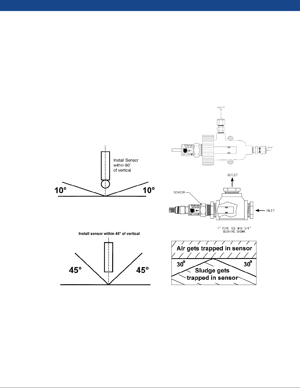
Figure 4. pH sensor recommended mounting orientation. pH sensors should be mounted at least 10° from the
horizontal to ensure correct measurement. Sensors can
also be mounted vertically.
Figure 5. Chlorine, dissolved oxygen, and ozone sensor
recommended mounting orientation. Chlorine, dissolved
oxygen, ozone sensors should be mounted vertically or
within 45° of the horizontal position. Also, these sensors
have recommended flow rates that should be observed.
Check instruction manual for more information on recommended flow rates.
Figure 6. Conductivity (contacting) sensors should have at
least 1/4 in. (0.6 cm) clearance between electrodes and
piping (as shown in both illustrations above). The recom-
mended sensor orientation is either horizontal or no more than
30° below horizontal. It is best that the inlet flow is facing the
sensor to ensure full pipe and minimal air bubbles.
4
Page 5
MOUNTING RECOMMENDATIONS FOR SENSORS
Metal Pipe
Plastic Pipe
True
Conductivity
Distance to Wall
Measured Conductivity
3/4 to 1 Toroidal
Sensor diameter
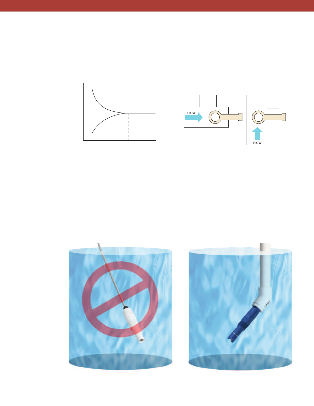
Conductivity (toroidal) sensors should be kept at a far
enough distance between sensor and pipe wall to ensure
the pipe wall does not interfere with the reading. If
clearance is too small, the sensor should be calibrated
Figure 7. The measured toroidal conductivity value can be
affected when installed close to a pipe wall.
Sensors submerged in tanks,
ponds, or basins
> To prevent leakage, wrap the sensor threads with pipe
tape before inserting into its mounting part.
> Do not over tighten the sensor when installing. Hand
tighten the sensor, and then tighten one or two (1–2)
turns with a wrench.
while in the pipe. The sensor should be completely
submerged in liquid. Mounting the sensor in a vertical
pipe run with the flow from bottom to top is best. If the
sensor must be mounted in a horizontal pipe run, orient
the sensor in the 3 o’clock or 9 o’clock position.
Figure 8. Correct sensor orientation
> The electrodes must be completely submerged in the
process liquid to measure properly.
> All sensor cables should be run through a pipe conduit;
do not use the sensors cable to dangle the sensor into
the tank, pond, or basin.
Do not install sensor by hanging it directly into water.
Incorrect Installation
Figure 9. Correct sensor installation is critical to to proper sensor performance.
Correct Installation
Always install sensor using pipe conduit.
5
Page 6
INSERTION SENSOR MOUNTING
he mounting parts contained in this section include in-
T
line tees, low flow cells, a handrail mounting assembly, a
floating ball system, a jet spray cleaner, mounting
dapters, and process connectors. The in-line tees are
a
offered in various configurations to assist in easy sensor
insertion and removal without twisting cables. The low
low cells are available for sidestream samples with 1/4"
f
OD tubing. The handrail mounting assembly is available
with all the parts needed to install a sensor into a pond
S
e
nsor
P
r
o
d
uct
N
um
b
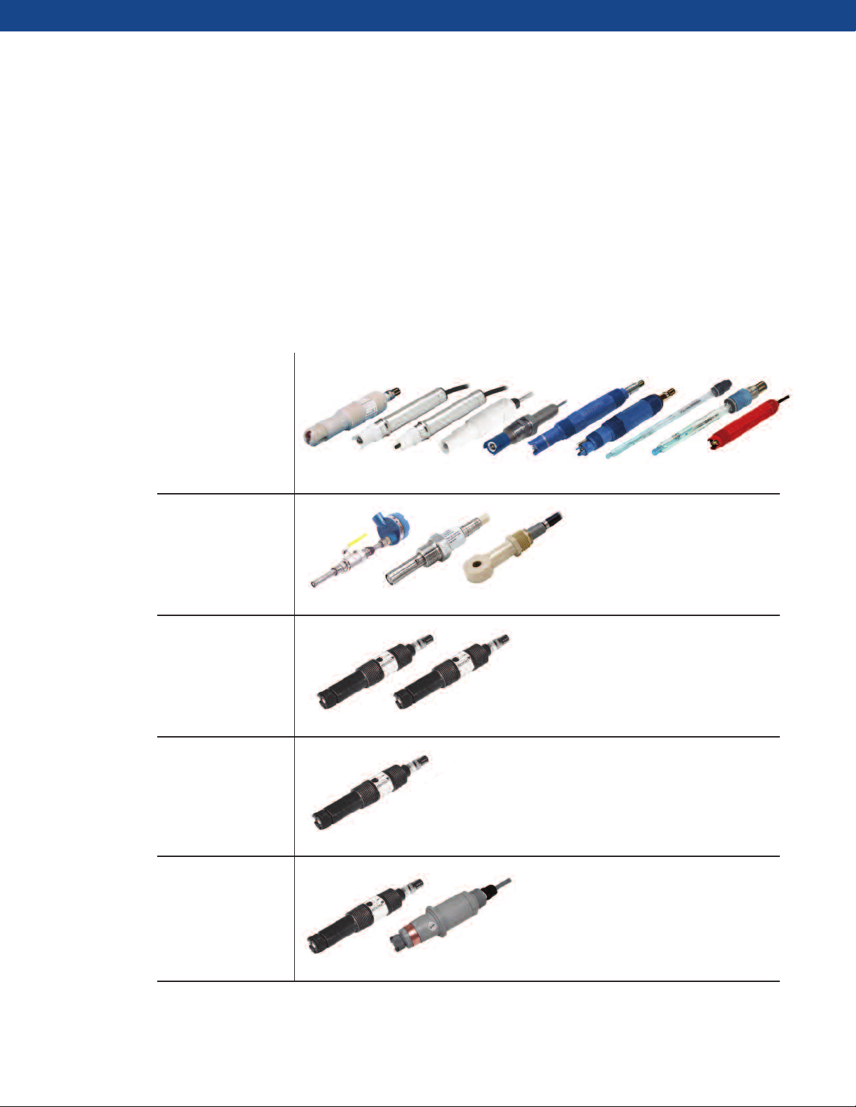
MEASUREMENT
e
TYPE
pH and ORP
389, 396, 396P
, T
F396, 3300HT
Conductivity
r basin; the jet-spray cleaner can be used with this
o
assembly for dirty applications. The floating ball system
can be used as an alternative method of installing a
ensor into a pond or basin. Many mounting adapters
s
are offered for tank and pipe insertion, as well as for
submersion applications. The process connectors are
ffered specifically for use with metal body sensors for
o
insertion, submersion, and retractable applications.
r
s*
, 3500, 3900, Hx338, 3800, RB546
140, 400, 228
Dissolved Oxygen
499ADO, 499AT
RDO
Ozone
4
99AOZ
Chlorine
499ACL, 498Cl
* Sensors with integral cable or VP connector can be used.
6
Page 7
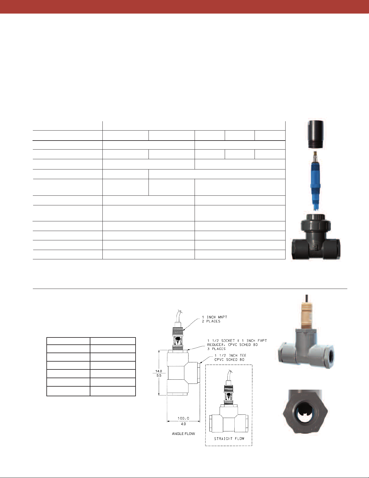
IN-LINE TEES
These versatile in-line tees can be used with Rosemount
Analytical pH, ORP, conductivity, dissolved oxygen,
ozone, and chlorine sensors having 1-inch process
connections. Compatible sensor models are listed in the
table below. Tees can be installed directly in process
piping or in slip streams. PN 23567-00 and PN 91524003, -04, and -05 have union fittings that allow the sensor
In-Line Tees
2002011 23567- 00 915240- 03 915240- 04 915240-05
Size 1.5" 2.0"
Process Connection Ends 1.0" thread 1.5" socket .75" threads 1.0" threads 1.5" threads
Material CPVC, Schedule 80 PVC, Schedule 80
O- ring or Gasket Material – Buna N
Maximum rating 150 psig (1136 kPa) 65 psig (549 kPa) 60 psig (515 kPa) at 120°F (49°C)
@150°F (65°C) @ 122°F (50°C)
Compatible Sensor Models*
pH and ORP 396P, 389, 3500, 3900 396P, 389, 3500,
Conductivity 150 –
Dissolved Oxygen 499ADO 499ADO
Ozone 499AOZ 499AOZ
Chlorine 499ACl 499ACl
*Note: All sensor models noted in this graph are listed with integral cables.
The sensor models with the “VP” connectors can also be used.
In-Line Tee Part Number
to be removed without the need to unscrew it, thus
eliminating the possibility of the cable becoming twisted
and damaged. Tees are offered in PVC and CPVC and can
connect to ¾, 1, and 1 ½ inch process lines.
lways install tees so that the sensor is completely
A
submerged in the process liquid, and allow enough
headroom to remove the sensor.
3900 using adapter PN S10283-LQD
Figure 10. When using sensor Model 3900VP
with Tee PN 915240-03, -04, or -05, order
adapter PN S10283-LQD (top of photo)
Direct mount into tee threads
IN-LINE TEE (PN 2002011)
PRESSURE/TEMPERATURE
SPECIFICATIONS
psig (kPa) °F (°C)
150 (1136) 150 (65)
128 (984) 160 (71)
102 (805) 170 (77)
80 (653) 180 (82)
57 (494) 200 (93)
48 (432) 210 (99)
FIGURE 11. 11⁄2 in. tee with 1 in. threaded process
connection (PN 2002011) shown with TUpH 396P
mounted for angle or straight process flow.
Figure 12. 389 pH sensor in
PN 2002011 Tee
Figure 13. Sensor tip in
process stream flow path.
7
Page 8
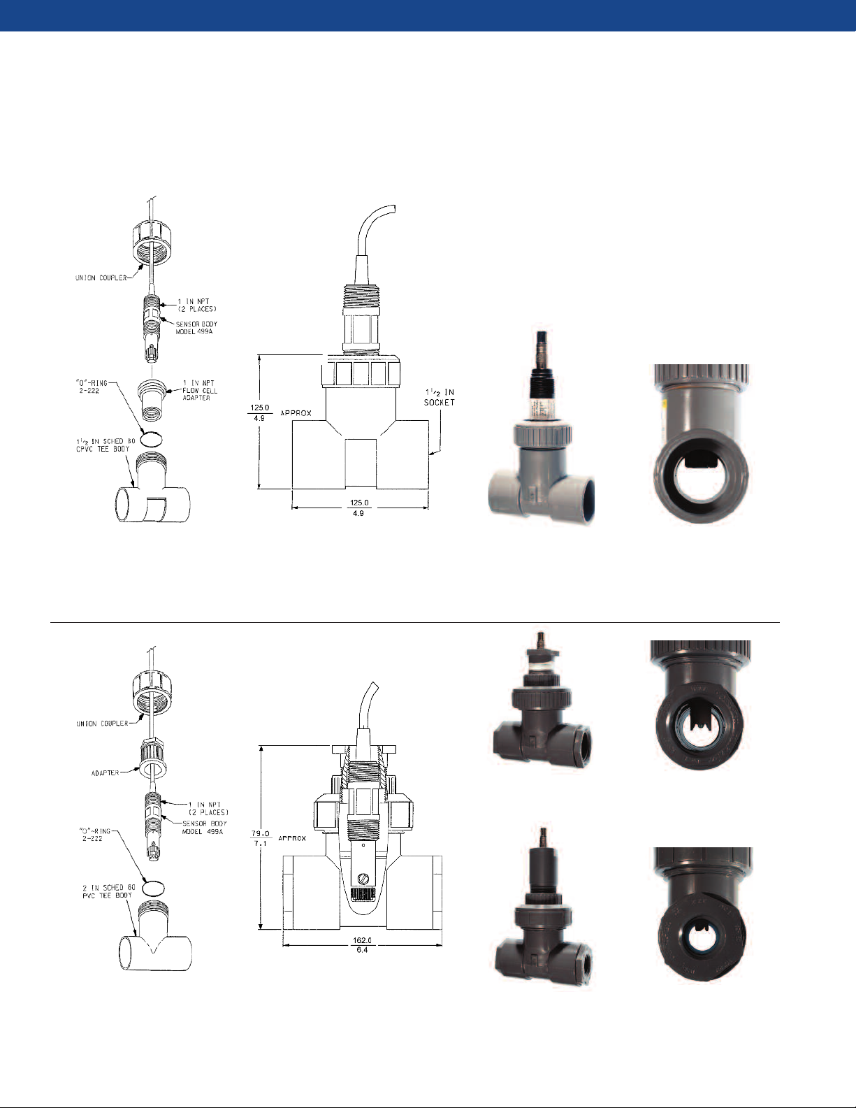
IN-LINE TEES
Tees with union adapters offer quick and easy access and eliminate damage from cable twisting.
Figure 14. 1½ in. tee with 1½ in. socket process connection (PN 23567-00)
shown with a Model 499A amperometric sensor. The tee assembly is offered with
a sensor mounting adapter that allows the user to remove the sensor without twisting
the cable.
Figure 15. 499ACL sensor
in PN 23567-00 Tee
Figure 18. PERpH-X
3500VP pH sensor in PN
915240-03 Tee
Figure 16. Sensor tip in
process stream flow path.
Figure 19. Sensor tip in
process stream flow path
Figure 17. 2 in. tee with ¾, 1, or 1½ in. threaded process connections (PN
915240-03, -04, -05 respectively) shown with a Model 499A amperometric
sensor. The tee assembly is offered with a sensor mounting adapter that allows the
user to remove the sensor without twisting the cable.
8
Figure 20. 3900VP pH sensor
in PN 915240-03 Tee with
adapter PN S10293-LDQ
Figure 21. Sensor tip in
process stream flow path
Page 9
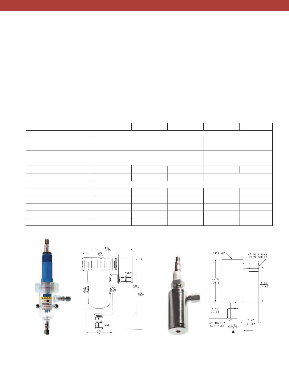
LOW FLOW CELLS
Emerson offers a variety of low flow cells for sidestream
applications where it is impractical to divert a large
volume of sample, particularly if the sample must be
sent to waste. Choose a transparent plastic or stainless
steel body—both have ¼ inch FPT process connections.
Plastic flow cells PN 24091-00, -01, and -02 are also
supplied with ¼ inch MPT to ¼ inch OD tubing fittings
Low Flow Cells
Process Connection 1/4 inch 316 SST male tube connector
Wetted Materials Body and Nut - Polycarbonate/polyester blend; 316 SST
Maximum Temperature 158°F (70°C) Consult Factory
Maximum Pressure 90 psig (621 kPa) Consult Factory
Sensor Threaded Connection 1 inch 1 inch 3/4 inch 1 inch 3/4 inch
Special features None
Compatible Sensor Models*
pH and ORP Sensors
Conductivity Sensors ––400, 400 VP – 400, 400 VP
Dissolved Oxygen 499ATrDO, 499ADO 499ADO – 499A DO –
Ozone 499AOZ ––––
Chlorine 499ACL 498CL, 499ACL –––
*Note: All sensor models noted in this graph are listed with integral cables. The sensor models with the “VP” designation can also be used.
PN 24091-00 PN 24091-01 PN 24091-02 S10240 (SQ 7716 ) S10290 (SQ 7637)
1/4" Fittings - 316 SST; O-ring - Silicone
Bubble shedding nozzle
396P, 389, 3500, 3900
– RB-546
and have a union connection that allows easy removal of
the sensor.
Valved rotameters are also available (see page 41) to
adjust and measure sample flow in sidestream
nstallations. Accurate control of flow is especially
i
important when measuring dissolved oxygen, chlorine,
and ozone.
None Order as a special request only
396P, 389, 3500, 3900
–
Figure 22. PN 24091-00
with 3900VP pH sensor
Figure 23. Low Flow Cell (PN 24091-00,
24091-01 or 24091-02) dimensions
Figure 24. PN S10290
with 400VP sensor
9
Figure 25. Metal Low Flow Cell
(PN S10240 and S10290) dimensions
Page 10
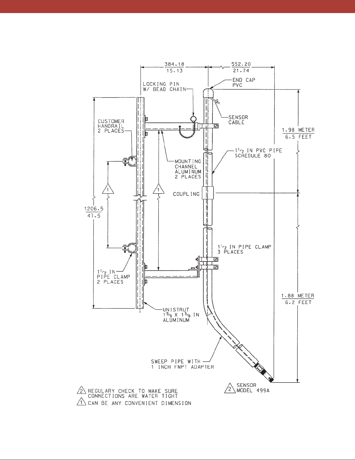
HANDRAIL MOUNTING
Use a handrail mounting assembly whenever a pH, ORP,
or dissolved oxygen sensor must be installed in a tank,
aeration basin, pond, or open channel. Two versions are
available. PN 11275-01 consists of a 13-ft (4.0-m) long
PVC pipe with a 45° bend about two feet (0.6 m) from
the lower end where the sensor is connected. The angle
allows bubbles to slide off the sensor. Clamps attach
the pipe to a frame that can be bolted to a handrail.
Handrail Mounting Assemblies
Part Number 11275-01
Process Connection Mounting brackets for Various Sizes of Handrails
Wetted Materials PVC NA NA
Temperature Rating 140°F (60°C) max. NA NA
Compatible Sensors*
pH and ORP Sensors 396P, 389, 3500, 3900
Dissolved Oxygen Sensors 499ADO**
Optional Accessory
* Note: All sensor models noted in this graph are listed with integral cables. The sensor models with the “VP”
connector can also be used.
* If used with the Handrail Mounting Assembly in a tank, the correct measurement can only be made if there is a
*
continuous flow or movement past the membrane of the sensor. These sensors will not operate properly in
standing liquid.
*** 1 1/2 inch pipe not supplied in these systems.
Jet Spray Cleaner (see pg 13)
HRMS-01
***
HMRS-02
***
The pipe insertion depth is adjustable. The HRMS
consists of a 1½ inch pipe clamp held by a clevis and
pin assembly, which can be attached to a railing. The
user supplies the 1 ½ inch pipe. The clamp can be
rotated from side to side and up and down and locked
in place once the pipe is in the desired position. The
sensor attaches to the pipe using either a threaded
adapter (HRMS-02) or a union coupling (HRMS-01).
HINT: Using a sensor with a VP connector and
cable will allow for easier access to the sensor
when cleaning or calibration is necessary.
Figure 26. Photo on left shows sensor being dangled into the pond, an incorrect installation. Photo on
right shows correct sensor mounting – sensor is threaded into a pipe conduit while cable is run through the
pipe of the Handrail Mounting Assembly.
10
Figure 27. HRMS-01 shown with usersupplied 1-1/2" pipe (top) and assembled (bottom).
Page 11
HANDRAIL MOUNTING ASSEMBLY
Figure 28. Handrail Mounting Assembly (PN 11275-01) shown with Model 499A Dissolved Oxygen Sensor.
11
Page 12
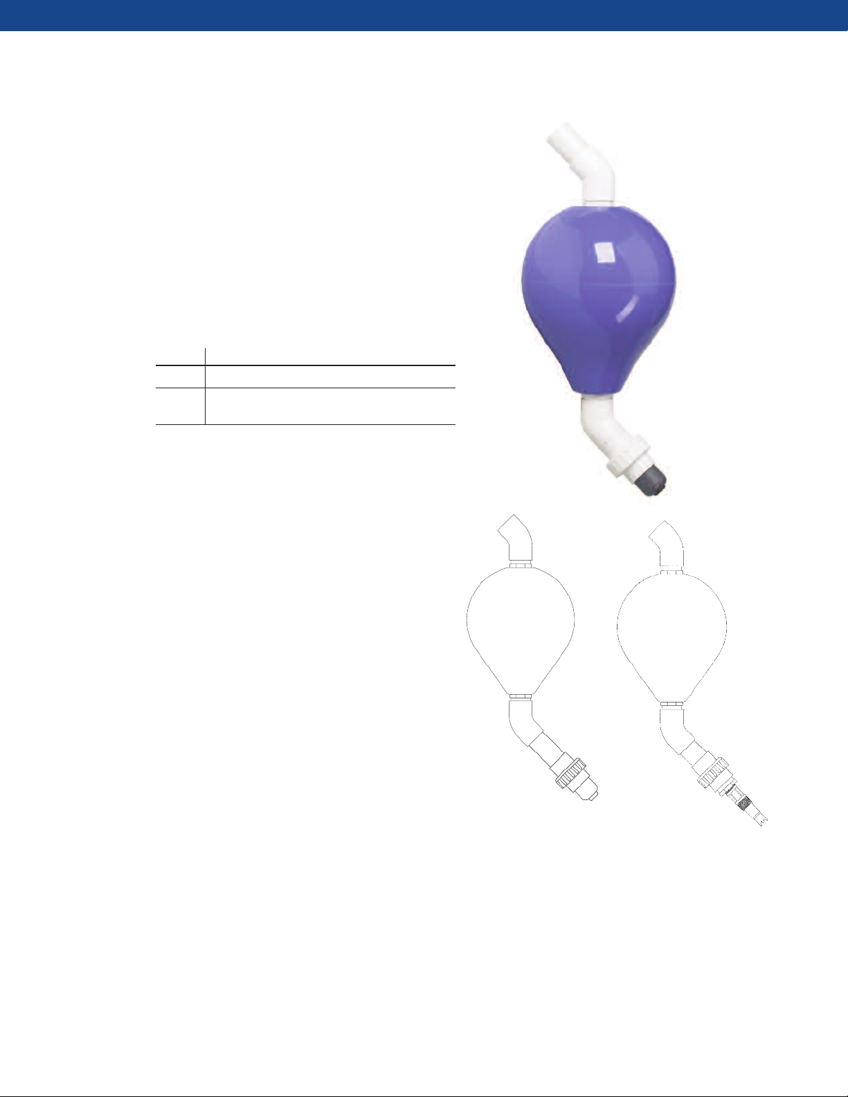
FLOATING BALL SYSTEM
The floating ball system when used with the HRMS
provides a convenient way of keeping the sensor a fixed
distance below the surface of a pond or basin
independent of the water level. The system
accommodates any sensor having 1-inch back facing
threads. The sensor attaches to the bottom of the float
through a union coupling, and the sensor is held a 45°
angle allows air bubbles to side off the sensor. The float
can be readily inflated using a hand pump.
Floating Ball System
Part No. Description
BB11-01 For Model 499ADO; includes sensor union adapter
BB11-03 For any sensor with a 1 inch rear-facing MNPT
connection; includes union adapter
Wetted Material: Flexible PVC, rigid PVC
Temperature Range: 32°F to 140°F (0°C to 60°C)
Size (Diameter x Length): 11 x 13 inches (28 x 33 cm)
Maximum Inflation Pressure: 2.1 psig (0.15 bar)
Maximum Circumference: 34-1/2 inches (88.0 cm)
Buoyancy: 27lbs (12 kg)
Minimum Sensor Insertion Depth Into Process:
BB11-01 with 499ADO sensor: 13 inches (33 cm)
BB11-03 with standard 1 inch sensor: 17 inches (43 cm)
Pipe Boom Support Arm: 1-1/2 inch Sch 80 PVC pipe
(by others)
Sensor Compatibility: 1 inch MNPT on sensor cable end
12
Figure 29. Assembled
Floating Ball BB11-01 for
the 499ADO dissolved
oxygen sensor
Figure 30. Floating Ball and
Sensor with 1 inch Rear Facing
MNPT Connection
Page 13
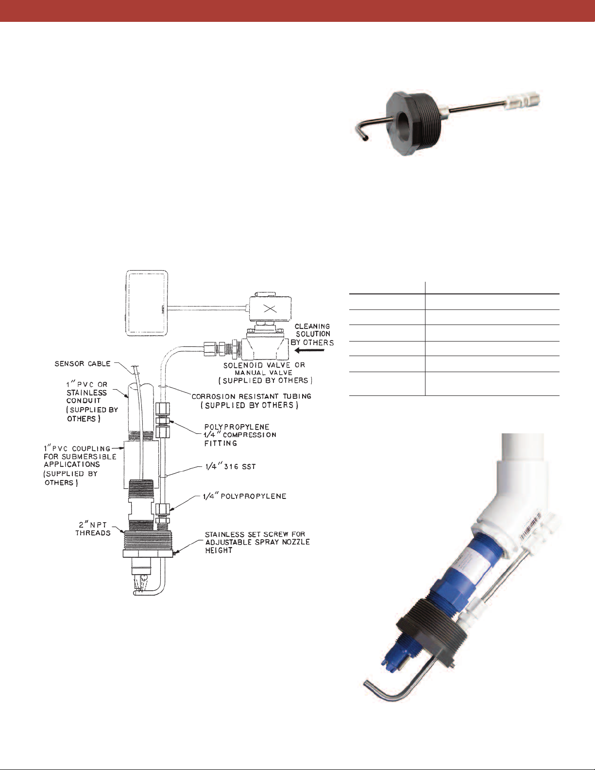
JET SPRAY CLEANER
The jet spray cleaner is intended for use with pH, ORP, or
oxygen sensors. It directs a spray of air, water, or other
cleaning fluid at the end of the sensor flushing away
suspended solids that have accumulated there. The
cleaner can be used only if the sensor is installed in a
tank or basin. It is not suitable for in-pipe installations.
Cleaning frequency and spray duration is controlled by
n interval timer in the analyzer. During cleaning the
a
analyzer can be programmed to hold the last reading,
thus avoiding spurious outputs and relay actions. Hold
can be continued beyond the end of the cleaning
Timer: supplied By
user or uTilize
imer funcTion
T
inside rosemounT
AnAlyTicAl
nsTrumenTs
i
period, allowing the sensor time to stabilize before the
analyzer returns to normal operation.
Cleaning intervals and frequency as well as the best
cleaning agent can be determined only by experience.
Several trials will likely be necessary to determine the
best program.
Jet Spray Cleaner
Part Number 12707-00
Process Connection 2" NPT threads OR use sensor/conduit
Wetted Materials 316 SST, polypropylene, PVC
Maximum Pressure 50 psig (446 Kpa)
Compatible sensors*
pH and ORP 396P, 389, 3900, 3500
Chlorine, dissolved 499ACL, 499ADO, 499AOZ
oxygen, and ozone
*Note: All sensor models noted in this graph are listed with integral
cables. The sensor models with the “VP” designation can also be used.
Figure 31. Example of Jet Spray Cleaner with timer and
solenoid valve for interval timed cleaning
Figure 32. Jet Spray Cleaner shown
with Model 3900 pH sensor using the
front threads to connect to the
cleaner and the back threads to
connect to a watertight pipe conduit
Typical install uses
these threads
13
Page 14
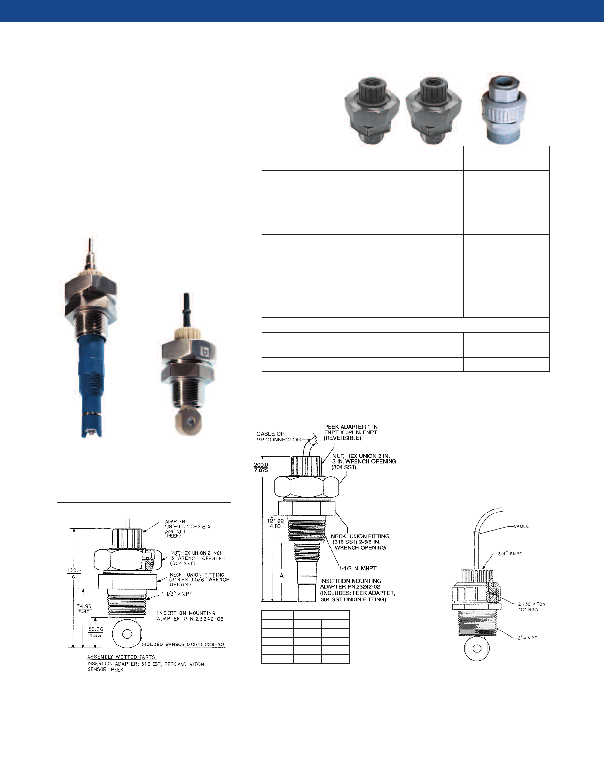
MOUNTING ADAPTERS – THREADED CONNECTIONS
Use these adapters to install sensors
with back facing threads into
process piping or sample tees. The
sensor screws into a plastic adapter
that is held in the process connector
by a union nut. The rear of the
adapter is threaded for a conduit
connection, if required. The union
connection allows the sensor to be
removed without the danger of
twisting and damaging the cable.
Mounting
Adapters
ADAPTER 23242-02 23242-03 2001990
Materials of 316 SST, 316 SST, CPVC, PEEK,
Construction PEEK, Viton PEEK, Viton Viton
Process Connection 1-1/2" MNPT 1-1/2" MNPT 2" MNPT
Sensor Adapter/ 1" x 3/4" FPT 3/4" x 5/8 - 3/4" x 3/4" FPT
Union Thread Size 11 UNC
Temperature, 392F (200C) 392F (200C) 100F(38C) at
Maximum
Pressure, 295 psig 295 psig 100 psig
Maximum (2135 kPa abs) (2135 kPa abs) (791 kPa abs)
Compatible Sensor Models*
pH and ORP 389, 396P
3500, 3900 --
Conductivity 228-21 228-20 228-21
*Note: Most sensor models noted in this graph are listed with integral cables. The
sensor models with the “VP” designation can also be used.
100 psig (791 kPa abs)
OR
185F (85C) at
45 psig (412 kPa abs)
Figure 33. 3500
PERpH-X pH sensor
with adapter
PN 23242-02
Figure 35. The 228 Toroidal Conductivity
Sensor with Adapter PN 23242-03
Figure 34. 228
Toroidal Conductivity
sensor with adapter
PN 23242-02 (or -03)
A “A” Dimension
Sensor* inches mm
396P 3.5 88.9
389 3.75 95.2
3900 4.5 114.3
3500 5.5 139.7
Figure 36. The 396P pH Sensor with Adapter
PN 23242-02. Can also be used for connection
to a 228-21 toroidal conductivity sensor using
the reversible PEEK adapter.
*The VP connector
versions can also
be used.
Figure 37. Adapter
PN 2001990 with 228-21
Toroidal Conductivity sensor
14
Page 15
MOUNTING ADAPTERS – SUBMERSION
Use this adapter to connect sensors with 1 inch back
facing threads to standpipes for installation in tanks
and basins.
Figure 38. Example of pipe mounting sensor with mounting
adapter PN 9320057.
Figure 39. 499ADOVP
Dissolved Oxygen Sensor
with adapter PN 9320057
ADAPTER 9320057
Materials of PVC, Sch 80
Construction
Process Connection 1" FNPT
Sensor Adapter/ 1" FNPT
Union Thread Size
Temperature, Ambient
Maximum
Compatible Sensor Models*
pH and ORP 389, 396P,
3500, 3900
Conductivity -
Dissolved Oxygen 499ADO
Ozone 499AOZ
Chlorine 499ACL
*Note: Most sensor models noted in this
graph are listed with integral cables. The
sensor models with the “VP” designation
can also be used.
15
Page 16

MOUNTING ADAPTERS – TRI-CLAMP®CONNECTIONS
Use these adapters to install threaded sensors into 1 ½
inch or 2 inch Tri-Clamp
®
process connections
Mounting Adapters
ADAPTER S10021 (SQ8940) SQP-10098-LQD* SQ 10904A & B
Materials of Construction 316 SST, 16 Ra finish 316 SST 304 SST
Process Connection 1.5" Tri-Clamp 2" Tri-Clamp
Sensor Adapter/Union Thread Size PG 13.5 1" 1" FNPT
Compatible Sensor Models**
pH and ORP 3800, Hx338 385+, 396, 396R, 398R, 389, 396P, 3500, 3900
TF396, 398, 3300HT, 3400HT
Conductivity –– –
Dissolved Oxygen Hx438 ––
* Formerly PN 23513-00
**Note: Most sensor models noted in this graph are listed with integral cables.
The sensor models with the “VP” connection can also be used.
2" (A) or 1.5" (B) Tri-Clamp
Figure 40. SQ10904 1.5" Tri-Clamp
adapter (bottom) and 2" adapter (top)
Figure 41. 396P TUpH sensors shown with
1 inch threaded, 1.5 and 2 inch Tri-Clamp
adapters
Figure 42. PN SQP-10098-LQD Compression fitting with
Tri-Clamp Flange shown on TF396 sensor
16
Page 17

PROCESS CONNECTORS FOR 1 INCH SENSOR TUBES
Certain models of pH and ORP sensors lack threads and
must be installed in the process piping using one of the
fittings shown below. The sensor slides into the fitting,
and a nut and ferrule tightened against the sensor tube
holds the sensor in place. The insertion depth is
adjustable. A collar on the tube prevents the sensor from
being ejected by the process pressure if the nut is not
sufficiently tightened. The fittings are available with 1-in
MPT and 2-in Tri-Clamp process connections. To prevent
the sensor from turning and twisting the cable while a
threaded fitting is being installed or removed, loosen the
nut to free the sensor.
Process Connectors
ADAPTER PN 23166-00 PN 23166-01 PN 9510066 SQP-10098-LQD**
Materials of Construction 316 Stainless Steel Titanium Nylon 316 Stainless Steel
O-Ring Material EPDM EPDM Polyethylene Viton
Process Connection 1" MNPT 1" MNPT 1" MNPT 2" Tri-Clamp
Sensor Tube OD 1" (25.4 mm) 1" (25.4 mm) 1" (25.4 mm) 1" (25.4 mm)
Compatible pH and 385+, 396, 398, 396R, 385+, 396, 398, 396R, 396, 398, 3300HT 385+, 396, TF396, 398,
ORP Sensors 398R, 3300HT, 3400HT 398R, 3300HT, 3400HT
*Note: Most sensor models noted in this graph are listed with integral cables. The sensor models with the “VP” designation can also be used.
**Formerly PN 23513-00
396R, 398R, 3300HT, 3400HT
17
Page 18

PROCESS CONNECTORS FOR 1 INCH SENSOR TUBES
Figure 43. Metal process connector (PN 23166-00 [316 SST] or PN 23166-01 [titanium]) shown with
TUpH Model 396 pH sensor. This process connector can be used for all 396, 398, and 3300HT sensor
installations. Also, it must be used for 396R, 398R, and 3400HT installations with or without a ball valve. See
ball valve section for more information.
Figure 44. The 23166-00 (or -01) metal
process connector, shown with the
3300HT PERpH-X sensor, allows various
insertions depths, depending on where
the user locates the compression fitting.
Also the threads can be switched to face
the top end of the sensor (right) for
connection to submersion pipes.
Figure 45. Nylon Process Connector PN 9150066 can be
installed with threads facing up or down. NOTE: This
connector should be used for low pressure, non-aggressive
chemical processes only.
Figure 46. 398 TUpH pH
Sensor with SQP-10098LQD Tri-Clamp flange
adapter
18
Figure 47. PN SQP-10098-LQD Compression fitting
with Tri-Clamp Flange shown here with TF396. Can
also be used with the 396, 398, and 3300HT sensors.
Page 19

RETRACTION ASSEMBLIES
Retraction assemblies allow a pH, ORP, or conductivity
sensor (both contacting and toroidal) to be inserted or
removed from a vessel or pipe without the need for
depressurizing or draining it. Insertion depth is
adjustable. Five retraction assemblies are available. Two
S
e
nsor
M
o
d
e
l
N
um
b
ME
A
S
UR
E
T
Y
PE
p
H
a
nd
O
R
Conductivit
MEN
P
y
T
385+, 396, 396P
228, 402
e
, 396R, 398, 398R, 3300HT
include the ball valve needed to close off the process
line before the sensor is removed. Two require the ball
valve to be purchased separately. The fifth assembly is a
rotary retraction valve.
r
s
, 3400HT
See following pages for retractable mounting options.
19
Page 20

RETRACTION ASSEMBLIES – BALL VALVE INCLUDED
Two retraction assemblies are available. PN 23240-00
has a 1 ½ inch full port ball valve and PN 23765-00 has a
1 ¼ inch ball valve. Both assemblies can be used with
the pH sensors listed in the table below. Model 402 and
402VP sensors can be used only with PN 23765-00.
PN 23765-00 includes a retraction chamber, 1 ¼ inch
ball valve, and close nipple for attaching the retraction
Ball Valve
Kits
1 1/2 in. Ball Valve Kit 1 1/4 in. Ball Valve Kit
Process Connections 1 1/2" FNPT 1 1/4" MNPT
Wetted Materials 316 SST 316 SST
Temperature Rating 32-212°F(0-100°C) 32-212°F(0-100°C)
Pressure Rating 100 psig (790 kPa) 200 psig (1481 kPa)
Maximum Retraction For 21 inch pH sensors: 64 psig (542 kPa)
Pressure 64 psig (542 kPa)
For 36 inch pH sensors:
35 psig (343 kPa)
Compatible
Sensor Models*
pH and ORP 396R, 398R, 385, 385+, 3400HT, RB-547
Conductivity – 402
Other information Use PN 23166-00 or -01 If ball valve is already
sensor to ball valve.** alone is available (PN 23796-00)
Use 1-1/2" close nipple (PN 93101-02)
to attach ball valve to FTP
process connection.
assembly to an FPT process connection. PN 23240-00
includes only the ball valve and retraction chamber. A
fitting (PN 23166-00 or 23166-01) is required to
connect the sensor to the retraction chamber, and a 1 ½
inch close nipple (PN 9310102) is needed to attach the
ball valve to a FPT process connection.
PN 23240-00 PN 23765-00
to connect available, the retraction assembly
* All sensor models noted in this graph are listed with integral cables. The sensor models with the
“VP” connector can also be used.
**Process connector is included with the 385 and 385+ sensors
Short insertion
Long insertion
Figure 48. Retractable sensors have the distinct advantage of having an adjustable
insertion depth. Sensor tubes can be installed with a short (top photo) or a longer
(bottom) insertion. See sensor model information for more about sensor tube lengths.
20
Page 21

RETRACTION ASSEMBLIES – BALL VALVE INCLUDED
pH sensors should be mounted at
least 10 degrees above horizontal
Conductivity sensors
should be mounted
between 0 and -30
degrees from the
horizontal
Figure 49. Examples of sensor mounting using a ball valve
retraction kit connected to a standard pipe tee, pipe “Y”, or
pipe weldolet.
To retract a sensor:
1) Loosen the retraction chamber or process connector
nut.
2) Slide the sensor into the retraction chamber. The
stop collar on the sensor prevents the sensor from
sliding out of the retraction chamber.
0
0
-
5
6
7
3
2
PN
Kit
lve
Va
ll
a
B
¼”
1
Figure 50. Observe the above mounting angles to obtain
best measuring results.
3) Close the ball valve.
4) Remove the process connector or retraction
chamber and sensor from the ball valve.
1.
” Ball Valve Kit PN 23240-00
½
1
Figure 51. Follow these four steps to easily remove the sensor from a pressurized system.
2
sensor out of process
e
Slid
.
retraction chamber
to
in
Close ball valve
3 .
4 .
t
u
n
n
Loose
21
Remove retraction
chamber plus sensor
Sensor stop collar
Page 22

RETRACTION ASSEMBLIES – BALL VALVE INCLUDED
BASENSOR TUBE
mm/in mm/in
LENGTH
327.7/12.9 586.2/23.1 21 in.
660.0/27.4 954.5/37.58 36 in.
Figure 52. 1½ in. FNPT Ball Valve Kit (PN 23240-00) shown with process connector (sold separately) and TUpH Model 396R
pH sensor. Ball valve kit includes a 1½ in. full port ball valve, a 1½ in. FTP to 1 in. FTP reducer (which serves as the retraction
chamber) and a 1½ in. close nipple that connects the reducer to the ball valve. A connector (PN 23166-00 or 23166-01) is required
to connect sensor to the reducer.
ro
P
PN
o
(s
q
re
sens
va
c
1
0
-
r
o
0
0
-
6
6
1
3
2
epar
s
ld
d
e
ir
u
r tub
o
it .
e k
lv
t
a
o
e to
tel
co
is
)
y
ct
e
n
n
the bal
e
th
l
Ball valve kit PN 23240-00 includes
1
inch ball valve, a close nipple
⁄2
a 1
o connect the reducer to the ball
t
1
lo
h c
inc
2
⁄
1
lu
inc
(not
ble fo
a
l
vai
a
an M
the 1
co
T
P
N
1
inch FNPT threads.
2
⁄
pple PN
e ni
s
ded in ball val
io
at
all
inst
r
n to
io
nnect
9310102
) is
e kit
v
ns requirin
e to
at
m
g
r
o
ct
e
n
n
Co
s
es
valve. The reducer is also the
retraction chamber.
Figure 53. Ball valve kit PN 23240-00 with other accessories (sold separately).
22
Page 23

RETRACTION ASSEMBLIES – BALL VALVE INCLUDED
Figure 54. 1¼ in. MNPT Ball Valve Kit (PN 23765-00 or 23765-01) shown with retraction kit and Endurance Model 402
conductivity sensor. Ball valve kit includes a 1¼ in. full port ball valve, a 1¼ in. nipple, and a retraction chamber.
Model A Dimensions B Dimensions C Dimensions
Minimum* Maximum
inches mm inches mm inches mm inches mm
402-11 3.21 82 5.34 136 18.13 460.5 1.19 30.2
402-12 2.34 59 4.47 114 17.33 440.2 1.19 30.2
402-13 2.36 60 4.49 114 17.33 440.2 1.19 30.2
402-14 3.89 99 4.91 125 18.83 478.3 1.19 30.2
396R-21 2.0 50.8 12.12 307.85 21 533.4 1.0 25.4
398R-21 2.0 50.8 12.12 307.85 21 533.4 1.0 25.4
3400HT-21 2.0 50.8 12.12 307.85 21 533.4 1.0 25.4
396R-25 2.0 50.8 26.62 676.15 36 914.4 1.0 25.4
398R-25 2.0 50.8 26.62 676.15 36 914.4 1.0 25.4
3400HT-25 2.0 50.8 26.62 676.15 36 914.4 1.0 25.4
*Minimum dimension must be met in order for sensor to measure correctly
Retraction
Chamber
1
" Full port ball valve
4
⁄
1
1
" nipple
4
⁄
1
Figure 55. The ball valve kit (PN 23765-00 or -01) has all parts needed to install the sensor. The retraction chamber
(PN 23796-00) can be purchased separately.
23
Page 24

RETRACTION ASSEMBLIES (BALL VALVES NOT INCLUDED)
These retraction assemblies are primarily intended for
use with Model 228 toroidal conductivity sensors.
owever, they can be modified for use with certain pH
H
and contacting conductivity sensors. Consult the
factory for information.
A mechanical (PN 23311-00) and manual (PN 23311-
01) retraction assembly are available. The mechanical
Shown with Model
28 Toroidal Sensor
2
retraction assembly, which uses a drive screw to insert
and retract the sensor, can be operated against a
ressure as high as 295 psig (2036 kPa abs). Both
p
retraction assemblies are fitted with 1/8" flush ports on
the retraction chamber to allow the sensor to be
ashed clean of sample before it is removed. Both
w
assemblies were designed to be used with a 1-1/2" full
port ball valve (purchased separately – PN 9340065).
hown with Model
S
228 Toroidal Sensor
PART NUMBER 23311-00 PART NUMBER 23311-01
Mechanical Retraction Assembly Manual Retraction Assembly
Process Connection 1.5" MNPT 1.5" MNPT
Wetted Materials 316 SST, Teflon, EP 316 SST, Teflon, EP
Maximum Operating Temperature 392°F (200°C) 392°F (200°C)
Maximum Operating Pressure 295 psig (2036 kPa) 295 psig (2036 kPa)
Max. Insertion/Retraction Conditions 392°F (200°C) 266°F (130°C)
295 psig (2036 kPa) 35 psig (241 kPa)
Maximum Insertion Travel 8.5" (21.6 cm) 12" (30 cm)
Maximum Insertion Travel 6.25" (15.9 cm) 7.0" (17.8 cm)
using PN 9340065 Ball Valve
Compatible Toroidal Model 228 Model 228
Conductivity Sensors
Compatible Contacting Consult factory for information Consult factory for information
Conductivity Sensors
Compatible pH & ORP Sensors Consult factory for information Consult factory for information
24
Page 25

RETRACTION ASSEMBLIES (BALL VALVES NOT INCLUDED)
Figure 56. Mechanical Retraction/Insertion Assembly
(PN 23311-00). To remove the sensor, use a socket
wrench to turn the drive screw until the sensor is inside
the retraction chamber. Close the ball valve (not shown)
and flush the retraction chamber. Loosen the hex union
nut. Remove the stop collar and the front half of the
guide clamp. Remove the sensor.
25
Figure 57. Manual Retraction/Insertion Assembly
(PN 23311-01). To remove the sensor, loosen the
collet nut and pull the sensor into the retraction
chamber. Close the ball valve (not shown) and flush
the chamber. Loosen the hex union nut and remove
the sensor.
Page 26

PASVE ROTARY RETRACTION VALVE
The PASVE is a mounting/service valve for pH sensors. It
allows the cleaning and calibration of pH sensors
without stopping the process. When required, this can
be done automatically.
hen using the sensor in abrasive processes, it can be
W
rotated to the measuring position only for the duration
of the actual measurement.
The PASVE valve is available in a manually operated type
or equipped with a pneumatic or electric actuator. It is
offered in a version for welding directly onto the pipe or
tank. It is also available with flanged connections.
Contact factory for more details.
Figure 58. PASVE valve, shown in welded on tank, manual
operation configuration
PASVE Specifications
Process Connections Code B: Welded on Tank at 15° angle
Code C: Welded on Tank
Code P: Welded on Pipe
Code F: Flange
Code D: Flow through with flanged connection
Wetted Materials (Valve) AISI 316LSST or Titanium
Wetted Materials (Seals) PTFE (Teflon) or PTFE (With carbon graphite filling)
Maximum Operating 482°F (250°C)
Temperature
Maximum Operating Pressure 570 psig (4000 kPa)
Cleaning Port Connections ¼ inch
Compatible pH Sensors 396, 396P, 389, 398, and 3300HT (with SQ9608)
385+, 396PVP, 3300HTVP (SQ 9608) and no others
26
Page 27

PASVE ROTARY RETRACTION VALVE
Figure 59. Operating PASVE Measuring Position Figure 60. Operating PASVE Servicing and Calibration
Position
Figure 61. Pasve valve with spring return, double action,
and pneumatic (left) or electric (right) actuator
Flush ports to connect cleaning liquid
or air to spray directly onto the sensor.
Spray tube from cleaning port.
Sensing end of the pH sensor.
Figure 63. PASVE Example of Flush Water Set-Up
Figure 62. Close-up of PASVE valve
with cleaning ports
27
Page 28

INSTRUMENT MOUNTING
The instrument mounting accessories found in this
section include instrument mounting kits for pipe or
wall mounting. These can be used with the following
Rosemount Analytical Instruments:
TWO-WIRE INSTRUMENTS
5081 Transmitter
Features a rugged, weatherproof,
corrosion-resistant enclosure.
> Meets NEMA 7B explosion proof
standards.
> Digital communication protocols:
®
HART
and FOUNDATION®fieldbus, allowing access to
AMS (Asset Management Systems)
1066
Tr
ansmit
Br
oad
r
ange
a
dv
anced
c
ap
a
b
i
lity,
>
U
ses
HA
F
O
UN
DA
T
comm
unic
>
U
se
r-
defina
WIRELESS INSTRUMENTATION
6081
Remote locations and installation
costs are no longer barriers to getting
information you require for critical
applications.
> 6081-C measures conductivity
> 6081-P measures pH
> Self-organizing network for
high data reliability and
network stability
> Industry leading wireless
security
of
comm
and
R
T
ve
IO
N
fie
ation
ble
te
mea
unic
uni
rs
ldbus
mea
que
io
pr
r
s
ur
ations
n
7
o
s
e
me
ea
se-
and
di
gital
tocols
ur
e
nts
me
F
OUR-WI
5
6
>
H
c
p
>
E
>
P
t
> Pr
to a
,
of
-
use
.
.
nt
dia
gnos
tic
p
ar
amet
e
> Pr
De
> T
Wid
1056
>
Sin
rs
.
>
L
allo
g
allo
>
E
1057
>
T
>
C
Contacting Conductivity/
Resistivity, in any combination.
A
n
ig
h
o
lo
a
r
a
x
t
e
r
o
c
r
e
n
ocess
op
r
ivat
P
C (Du
g
a
rg
w
l
ance
wable
a
s
y to ins
hr
e
hoo
a
ly
r
eso
r
f
o
r
met
n
s
iv
e
ess
d
din
g
d
USB d
or
t
ional,
ive
t
t
h Mod
A
n
aly
le
or
e,
e
a
s
op
if
A
n
aly
e-in
se
f
R
E
ze
r
lu
imme
e
r
.
h
e
is
r
g
r
aphs
ata c
r
ive.
(PID
y Cy
zer
d
ual in
s
y
-to-r
e
r
t
he
par
tall an
zer
pu
t
r
om p
I
t
io
lp
u
ul
ators
pr
a
NS
T
R
UM
n
sc
r
e
e
n
d
i
a
t
e
r
e
sc
r
e
e
n
s
p
t
io
n
s
c
a
n
.
an b
e
do
Inte
g
r
a
l an
) c
ont
r
ol.
cle
C
ont
r
ol/Pulse
a
t
ion).
pu
t
ana
e
ad
displ
kno
w
ocess
is
amete
rs
.
d
w
ir
e.
naly
ze
r.
H/ORP/ISE or
c
f
w
at
w
E
s
h
o
o
b
ly
NT
o
w
g
n
it
r
r
a
e
p
nload
d
ze
r.
a
y
a
it
hin
S
s
fa
u
lt
s
a
n
d
w
a
r
n
in
g
s
in
io
n
o
f
a
n
o
u
t
o
f
r
a
n
g
e
p
id
s
ta
r
t
u
p.
in
p
o
int
e
d
in
t
h
e
c
o
lo
r
e
d
28
Page 29

INSTRUMENT MOUNTING ACCESSORIES
R
os
e
m
o
u
n
t
A
na
l
y
ti
c
a
l
in
s
tru
m
e
n
ts
c
a
n
b
e
m
o
p
i
p
e,
in
a
p
a
n
e
l
,
or
on
a
w
a
ll
u
s
in
g
the
v
a
r
i
o
u
s
m
o
u
n
tin
g
a
c
c
e
s
s
or
i
e
s
.
T
he
s
e
k
its
c
on
t
a
in
a
ll
p
n
eed
ed
for
a
s
u
c
c
e
s
s
f
u
l
in
s
tru
m
e
n
t
in
s
t
a
ll
a
ti
on
Mounting part 23820-00 23820-01
Bracket Carbon Steel, blue epoxy coating 316 SST
Bracket Dimensions 7.5" x 4.0" x 1.2"
U-Bolt SST
U-Bolt Dimensions for 2" pipe maximum
Screws and washers SST
Compatible Instruments 56, 1056, 1057, 1066, 5081, 6081
u
n
t
ed
v
e
rsa
ti
a
r
ts
.
PN 23820-00 and 23820-01 are Mounting Bracket Kits
on
a
for Pipe, Surface or Wall Mounting. Kit includes one
le
bracket and two u-bolts with washers and screws. Use
for mounting Rosemount 56, 1056, 1057, 1066, 5081,
and 6081 instruments.
Figure 64. These two graphics are examples of pipe or wall mounting a 6081 instrument using
either of the mounting bracket kits. On the left is an example of the instrument mounting onto a
pipe. On the right, the instrument uses the kit to mount onto a wall. Other Rosemount Analytical
instruments can be mounted similarly.
29
Page 30

INSTRUMENT MOUNTING ACCESSORIES
165
6.5
130
5.1
33.5
1.3
232
9.1
2 INCH PI PE SUPPLIED
BY CUSTOMER
SIDE VIEW
0.85”
22 mm
4.0”
102 mm
1.2”
30.5 mm
1.2”
30.5 mm
0.85”
22 mm
3.0”
76 mm
6.5”
1
65 mm
2
.8”
7
1 mm
3.0”
76 mm
Figure 65. 5081 pipe mounted with the
PN 23820-01 SST Kit.
Figure 67. 1056 shown mounted on a pipe using either pipe
mount kit, side view.
30
Figure 66. Dimensions of the mounting bracket found in
kits PN 23820-00 and 23820-01
Figure 68. The 1056 is shown mounted on a wall/surface
using either pipe mount kit, side view.
Page 31

WIRING ACCESSORIES
This section features junction boxes and cables compatible with
Rosemount Analytical sensors and instruments.
Cable Extensions through Junction Boxes
Use a junction box when the analyzer must be installed
urther from the sensor than the standard cable length
f
allows. To replace the sensor, disconnect the cable at
the junction box. The cable between the junction box
and the analyzer never needs to be disturbed.
> The distances between the sensor and instrument are
recommendations only.
> Long cable distances may degrade the signal; for best
performance, install long cable runs in a noise-free
environment.
> For contacting conductivity sensors, long cable runs
will result in some loss of linearity.
> Consider an Emerson Wireless solution instead.
Mount the analyzer within standard cable length of
the sensor and send the signal wirelessly to the
control room. Emerson offers wireless pH and conductivity instruments as well as the THUM, which
converts any Rosemount Analytical HART instrument
into a wireless device. All wireless instruments require
a Model 1420 Gateway to receive the signal.
Best Practice Tip
The best practice for extended distances are recommended below to assist with the easiest sensor replacement. Follow this guideline when installing sensors at a
long distance from the instrument:
1. Install the junction box closest to the sensor.
2. Use an extension cable to run the signal from the
junction box to the instrument. The use of factory
prepared cable is strongly recommended. The cables
designated as “prepped” are prepared with the cable
jacket and all of the wires stripped and ready for a
quick installation.
3. Distances between the sensor and instrument are
cumulative and include the sensor cable plus the
extension cable. For instance, if the maximum cable
required is 200 ft (61.0 m) and the sensor cable is 15
ft (4.6 m), the extension cable maximum length is
185 ft (56.4m).
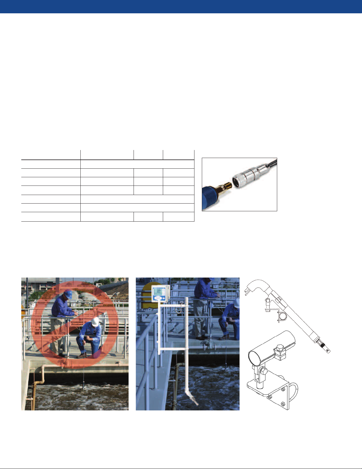
Chlorine, Dissolved Oxygen, and Ozone Sensors
Sensor to Analyzer Separation Distances
Sensor Cable Length
Measurement Sensor Standard Junction Box Prepped Unprepped
Dissolved Oxygen 499ADO 25 ft (7.6m) 200 ft (61.0m) 23550-00 23747-00 9200275
Chlorine 498CL or 499ACL 25 ft (7.6m) 200 ft (61.0m) 23550-00 23747-00 9200275
Ozone 499AOZ 25 ft (7.6m) 200 ft (61.0m) 23550-00 23747-00 9200275
Chlorine, Dissolved
Oxygen or Ozone
Sensor
Standard sensor
cable or VP cable
(50 ft (15m) max)
Maximum recommended distance between sensor and instrument is 200 ft (61.0m)
Recommended maximum distance
between sensor and instrument*
Junction box
PN 23550-00
31
Extension cable
Extension Cable
Analyzer
Page 32

WIRING ACCESSORIES
Conductivity Sensors
Sensor to Analyzer Separation Distances
Sensor Cable Length
Recommended
maximum distance
etween sensor and
Measurement Sensor Standard Optional Junction Box Prepped Unprepped
b
instrument*
140, 141, 142 No Cable; use extension cable 200 ft (61.0m) Included 23747-00 9200275
Contacting 150 10 ft (3.1m) 200 ft (61.0m) 23550-00 23747-00 9200275
Conductivity 400, 401, 403, 404 10 ft (3.1m) 50 ft (15.2m) 200 ft (61.0m) 23550-00 23747-00 9200275
402 10 ft (3.1 m) 200 ft (61.0m) Included 23747-00 9200275
225, 226, 228 20 ft (6.1m) 200 ft (61.0m) 23550-00 23294-04 9200276
Toroidal 222 20 ft (6.1m) 100 ft (30.5m) 23550-00 23294-04 9200276
Conductivity 242, 245 Use extension 200 ft (61.0m) Included 23909-00
(flow through) cable
Extension Cable
Contacting
Conductivity
Sensors
Toroidal
Conductivity
Sensors
Standard sensor
cable or VP cable
(50 ft (15m) max)
J
unctio
P
N
n
23550-
b
o
x
00
Extension cable
Maximum recommended distance between sensor and instrument is 200 ft (61.0m)
Standard sensor
cable or VP cable
(50 ft (15m) max)
Junction box
PN 23550-00
Extension cable
Maximum recommended distance between sensor and instrument is 100 ft (30.5m) to 200 ft
(61.0m) depending on the sensor model. See chart for more information.
Analyzer
Contacting or Toroidal
Conductivity Sensors with
sensor mounted junction box
Maximum recommended distance between sensor and instrument is 200 ft (61.0m)
Extension cable
32
Page 33

WIRING ACCESSORIES
pH and ORP Sensors
Sensor to Analyzer Separation Distances
Sensor Cable Length
Recommended
maximum distance
etween sensor and
Measurement Sensor Standard Optional Junction Box Prepped Unprepped
b
instrument*
No preamp 15 ft (4.6m) 200 ft (61.0m) 23555-00 23646-01 9200273
pH Sensors in the sensor (contains preamp)
Preamp in the sensor 25 ft (7.6m) 200 ft (61.0m) 23550-00 23646-01 9200273
Preamplifier in Sensor No Cable; 200 ft (61.0m) - 23646-01 9200273
Mounted Junction Box use extension cable
pH or ORP Sensor NON preamplified
version
Extension Cable
pH or ORP Sensor with
integral preamplifier
pH or ORP Sensor with
integral preamplifier
Standard sensor
cable or VP cable
(50 ft (15m) max)
Junction box PN 23555-00
WITH preamplifier
Extension cable
Maximum recommended distance between sensor and instrument is 200 ft (61.0m)
Standard sensor
cable or VP cable
(50 ft (15m) max)
Junction box PN 23550-00
with extension board
Extension cable
Maximum recommended distance between sensor and instrument is 200 ft (61.0m)
Extension cable
Maximum recommended distance between sensor and instrument is 200 ft (61.0m)
33
Page 34

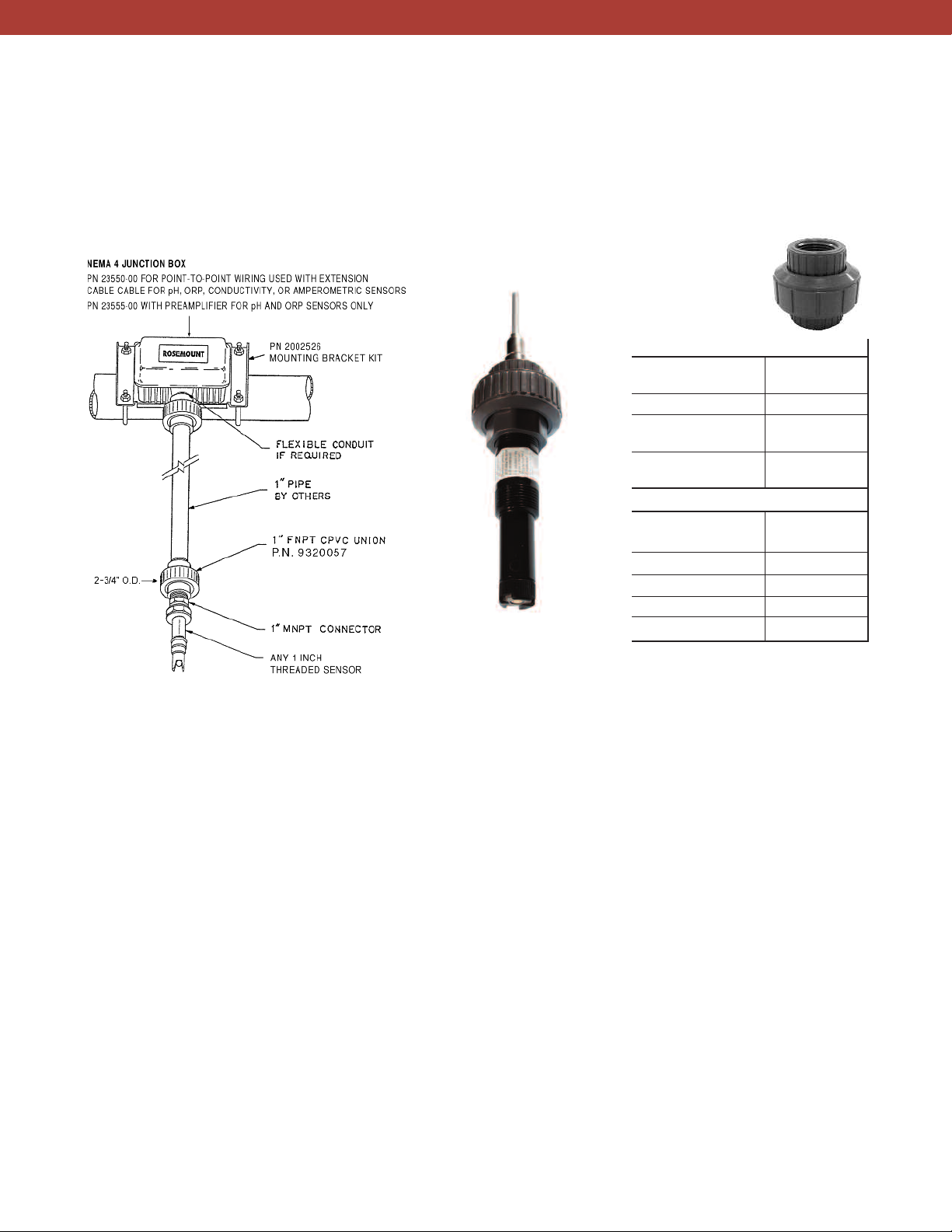
REMOTE JUNCTION BOXES
Use remote junction boxes to extend the sensor cable
for longer runs. Two captive screws allow easy access to
the board inside the box. There are two ports for cable;
the bottom port is for the sensor cable and the side port
is for the extension cable. These weatherproof junction
boxes are also ideal for indoor mounting.
> PN 23550-00 can be used to extend the cable of
lmost any Rosemount Analytical sensor. The terminal
a
board allows point-to-point wiring between the
sensor and extension cable.
> PN 23555-00 has an integral preamplifier (PN 23557-
00) and is used for pH and ORP sensors only. The
preamplifier has FM, CSA and ATEX approval for use in
hazardous locations. Any non-preamplified
Rosemount Analytical pH or ORP sensor can be used
with this junction box. The preamplified signal is
compatible with Rosemount Analytical 56, 1056,
1057, 1066, 5081, and 6081 instruments.
> Both junction boxes have identical dimensions.
Figure 69. Junction Box PN 23550-00.
Figure 70. Junction Box PN 23550-00 is used for extending
any Rosemount Analytical sensor’s cable by connecting the
sensor cable to an internal extension board. Extension cable
sold separately.
Figure 71. Junction Box PN 23555-00 is used for pH and ORP
sensors only. A preamplifier board is mounted internally.
Figure 72. Junction Box PN 23555-00 dimensions.
Junction Box PN 23550-00 has identical dimensions.
34
Page 35

MOUNTING BRACKET FOR REMOTE JUNCTION BOXES
Remote mount junction boxes can be mounted on a
wall or pipe using the Mounting Bracket PN 2002526.
Mounting Bracket Specifications
Mounting part 2002526
U-Bolt SST
U-Bolt Dimensions for 2" pipe maximum
Screws and washers SST
Compatible Junction Boxes 23550-00 and 23555-00
SENSOR HEAD JUNCTION BOX
Sensor Head Junction box PN 23709-00 is for use with
all Rosemount Analytical retractable style pH and ORP
sensors. It is mounted on the back end of the sensor
using a compression fitting. The junction box contains
an integral preamplifier (PN 23557-00) and has terminals to connect an extension cable (sold separately)
directly to an instrument.
11.5 inches
292 mm
.4 inches
4
—————
—
12 mm
1
> Dimensions: 5"D x 5
3
⁄8" H x 4"W
> Materials: Aluminum Alloy
> Preamplifier: FM, CSA, ATEX
> Compatible Sensors: 396R, 398R, 3400HT and RB547
35
Figure 72. Sesor Head Junction Box PN PN 23709-00.
Page 36

VP CONNECTOR CABLES, EXTENSION CABLES, AND CABLE GLANDS
Rosemount Analytical offers various extension and
connector cables for the best EMI protection in the
industry. VP connector cables are used with sensors
VP Connector Cables
pH and ORP Sensor Cables
The VP8 connector cable is compatible with the
following sensors: 3300HTVP, 3400HTVP, 3500VP,
3900VP, 389VP, 396VP, 396PVP, 396RVP, 398VP,
398RVP, HX338, 3800VP.
Part Number VP8 Cable for pH & ORP sensors
Feet Meters
24281-02 2.5 0.8
24281-05 4 1.2
24281-06 10 3.0
24281-00 15 5
24281-07 20 6.1
24281-01 25 7.6
24281-08 30 9.1
24281-03 50 15.2
24281-04 100 30.5
having VP quick disconnect fittings. Extension cables are
used with sensor mounted or remote junction boxes.
Follow this simple guide to select the appropriate cable.
The VP8 Cable PN 24281-XX is a 6 conductor cable with
1 coax and 3 shields.
Jacket Material: PVC
Jacket Maximum Diameter: 0.31 inches
Temperature Range: -40C to 105C; sunlight resistant
Figure 73. VP8 connector cables (bottom) can be used with
all pH and ORP sensors with a VP designation. 3500VP (top)
and 396PVP shown.
Conductivity, DO, OZ, and Chlorine Sensor Cables
VP6 cable PN 23747-XX is compatible with the following
sensors: 400VP, 402 VP, 403VP, 499ACL-VP, 499ADO-VP,
400ATrDO-VP, and 499AOZ-VP. For 410VP (four-electrode
contacting sensor) use PN 24287-00 or -01.
VP6 Cable
for conductivity,
dissolved oxygen, ozone
& chlorine sensors
Part Number Feet Meters
23747-02 10 3.0
23747-03 50 15.2
23747-04 4 1.2
23747-05 2.25 0.7
23747-06 2.5 0.8
23747-07 15 4.6
23747-08 20 6.1
23747-09 25 7.6
23747-10 30 9.1
23747-11 100 30.5
24287-00 10 3.0
24287-01 20 15.2
The VP6 Cable PN 23747-XX is a 3 conductor cable with
2 coax and 3 shields.
Jacket Material: PVC
Jacket Maximum Diameter: 0.31 inches
Temperature Range: -40C to 105C; sunlight resistant
The VP6 cable PN 24287-XX is a cable with 2 twisted
pairs and 1 triad.
Jacket Material: PVC
Jacket Maximum Diameter: 0.31 inches
Temperature Range: 0C to 105C; sunlight resistant
Figure 74. VP6 connector cables can be used with conductivity and amperometric sensors with a VP designation.
499ADO-VP and 400VP (bottom) shown.
36
Page 37

EXTENSION CABLES
Rosemount Analytical offers two types of cables; prepped
and unprepped. The unprepped cables are raw cables;
user must cut the cable jacket and strip all of the wires
before use. The cables designated as prepped are
prepared with the cable jacket and all of the wires stripped
and ready for quick installation. The use of factoryprepped cables is strongly recommended. All extension
cables can be ordered at user specified length.
pH and ORP Sensor
Extension Cables
3300HT/HTVP
3400HT/HTVP
3500/VP
3900/VP
385+
389/VP
396/VP / 398/VP
396P/VP
396R/VP 398R/VP
398R/VP
Cable Part No. Cable Description
9200273 Gray Ext Cable, 11-cond, shielded, unprepped XXX XXXXXXX
23646-01 Extension Cable, 11-cond, shielded, XXX X XX XXX
prepped (raw cable PN 9200273)
Conductivity
Amperometric*
Conductivity and Amperometric
Sensor Extension Cables
Cable Part Extension Cable Description
Number
9200275 Shielded 9-cond, unprepped XX X
9200276 Unprepped XXX
9200334 For 410VP sensor X
23294-00 Unshielded, Prepped XX
23294-04 Shielded for improved EMI/RFI protection. XX
Prepped
23294-05 Shielded with additional shield wire for -03 option. XX
Prepped
23747-00 Prepped XX X X
23909-00 Prepped XXX
24289-00 For 410VP sensor X
9200275 is the raw cable for prepped cable 23747-00
9200276 is the raw cable for prepped cables 23909-00, 23294-00, 23294-04, 23294-05
* Amperometric sensors measure dissolved oxygen, ozone, and/or chlorine
140, 141, 142
150
222
225, 226, 228
242
245
400 & 400VP, 401,
402 & 402VP, 403
& 403VP, 404
410VP
499ACl, 499ADO
499AOZ,
499ATRDO
Cable Glands
Use cable glands to seal the cable where it enters the
analyzer or junction box. Cable glands also prevent the
weight of the cable from pulling on and dislodging
wiring connections in the analyzer. Cable gland kit PN
23554-00 provides 5 cable glands that fit all Rosemount
Analytical instruments and junction boxes.
37
Figure 75. Cable gland found in kit PN 23554-00
Page 38

CALIBRATION ACCESSORIES
Portable Conductivity Validation Unit
he conductivity validation unit (CVU) consists of a
T
factory-calibrated Model 1056 conductivity analyzer
and Model 404 flow-through conductivity sensor
oused in a rugged carrying case. The CVU is ideal for
h
applications where calibrating a conductivity sensor
against a standard solution is impractical. This includes
ensors that cannot easily be removed from the process
s
piping and sensors having 0.01/cm cell constants for
which stable low conductivity calibration standards are
not available. The CVU is widely used for calibrating
conductivity sensors in water for injection applications.
Using the CVU is easy. Connect the Model 404 sensor in
series with the process sensor using the tubing provided
with the CVU. Allow the sample to flow past both
sensors. Once readings are stable, adjust the process
analyzer reading to match the CVU reading.
The calibration system is completely enclosed. The solution never contacts atmospheric carbon dioxide, which
can contaminate low conductivity standards, leading to
erroneous calibration. Thus, the CVU is ideal for calibrating 0.01/cm cell constant sensors.
Figure 76. The 1056 conductivity instrument and 404
conductivity sensor are hard mounted into a protective
case. Each unit includes all cabling and tubing needed for
connection to a water system.
The CVU is available in two versions:
> CVU-01: One 404-11-17 Stainless Steel Sensor with a
0.01 cell constant pre-wired to the 1056-01-20-38-AN
analyzer.
> CVU-02: Two sensors, one 404-11-17 Stainless Steel
Sensor with a 0.01 cell constant and one 404-12-17
Stainless Steel Sensor with a 0.1 cell constant prewired to the model 1056-01-20-30-AN analyzer.
See Product Data Sheet PDS 71-CONDVALII for more
information.
38
Page 39

CALIBRATION STANDARDS
pH Buffer Solutions
Emerson offers pH 4.01, pH 6.86, and pH 9.18 NIST
buffer solutions that meet most pH calibration requirements. Accuracy is ±0.02 pH at 25°C (77°F). A chart listing
the pH of the buffer at other temperatures is provided on
the label.
Other buffer solutions, pH 4.00, pH 7.00, and pH 10.00,
are available. These solutions are color-coded for easy
recognition. They are available as single bottles or in
packages of six.
All Rosemount Analytical pH instruments have an auto-
matic buffer calibration features that recognizes the pH of
the buffer and uses the temperature-adjusted pH value
during calibration.
A 475 mV ORP (redox) standard solution is also available.
Part Number Description Size Color Code
9210012 Rosemount Analytical pH 4.01 buffer solution 16 oz (473 ml) Pink
9210013 Rosemount Analytical pH 6.86 buffer solution 16 oz (473 ml) Clear
9210014 Rosemount Analytical pH 9.18 buffer solution 16 oz (473 ml) Clear
905-3506 pH 4 buffer solution 16 oz (473 ml) Red
905-582517 6 pack of pH 4 buffer solution (PN 905- 3506) Box of 6 16 oz (473 ml) bottles Red
905- 3501 pH 7 buffer solution 16 oz (473 ml) Green
905- 582521 6 pack of pH 7 buffer solution (PN 905- 3501) Box of 6 16 oz (473 ml) bottles Green
905- 3505 pH 10 buffer solution 16 oz (473 ml) Blue
905- 582525 6 pack of pH 10 buffer solution (PN 905- 3505) Box of 6 16 oz (473 ml) bottles Blue
R508- 8oz ORP Standard, 475mV, 8oz 8 oz (237 ml) NA
Conductivity Standards
Emerson offers a variety of conductivity standards in
both 16 oz (473 mL) and 1 gal (3.8 L) sizes. To determine
the best standard to use, consult the analyzer product
data sheet and choose a standard whose conductivity is
in the recommended range for the cell constant.
Part Number Standard Solution Value Size Color Code
05010781899 (SS- 6) 200 μS/cm 16 oz (473 ml) Red
05000705464 (SS-1) 1409 μS/cm 16 oz (473 ml) Blue
05010782468 (SS-5) 1000 μS/cm 16 oz (473 ml) Yellow
05010782147 (SS-7) 5000 μS/cm 16 oz (473 ml) Violet
05010797875 (SS- 6A) 200 μS/cm 1 gallon (3.8 L) Red
05000709672 (SS-1A) 1409 μS/cm 1 gallon (3.8 L) Blue
05010783002 (SS-5A) 1000 μS/cm 1 gallon (3.8 L) Yellow
05010782026 (SS-7A) 5000 μS/cm 1 gallon (3.8 L) Violet
39
Page 40

CALIBRATION ACCESSORIES
Bench Top Calibrator
he bench top calibrator lets you take full advan-
T
tage of the power of Emerson’s SMART pH
sensors. Instead of carrying buffer solutions,
eakers, a waste container, and a wash bottle
b
into the plant to calibrate the sensor, just discon-
nect the SMART sensor and bring it to the
hop or laboratory. Connect the sensor to
s
the bench top calibrator and complete
the calibration. The results are auto-
matically stored in the sensor. When
the sensor is reconnected to the field
analyzer, it transfers the stored calibration data to the field instrument.
The calibrator has a pre-wired VP cable
and pre-wired spring-loaded push connec-
ors, so it can be used with both VP and integral cable
t
sensors. Although the calibrator is most convenient for
use with SMART sensors, it can also be used with non-
MART pH sensors. In the latter instance, the user notes
S
the calibration data and enters it manually in the field
instrument.
The bench top calibrator (PN S10119) consists of a dual
channel Model 1056 pH analyzer—one channel
connected to the VP cable, the other to the push
connectors—mounted on a stand with openings in front
to accommodate three 250 mL beakers for buffers and
rinse water. Beakers are not provided.
pH sensors and buffers solutions are sold separately. See
product data sheet PDS 71-BTC for more information.
Handheld pH Simulator
The handheld pH simulator PN S10104 (SQ7428)
supplies switch-selectable pH 4, 7, and 10 inputs to an
analyzer. Two other switches allow the user to simulate
a cracked glass membrane and a coated reference junction. The simulator is compatible with any Rosemount
Analytical pH instrument. The unit is battery operated.
Consult the factory for more information.
pH and Conductivity Simulator Module with VP plug
Simulator modules, when connected to a VP cable,
simulate either a pH or contacting conductivity sensor.
They are used for checking the proper working of the
cable and analyzer.
PN SQ8705 simulates pH 7.00, 25°C, 100 MΩ glass
impedance, and 5 kΩ reference impedance. Use it with
any VP pH cable having part number 24281-XX.
PN 23979-00 contains two modules for checking VP
conductivity cables and conductivity analyzers. One
module puts a 20 kΩ resistor across the electrode
terminals; the other puts a 100 kΩ
resistor across the terminals. The
expected conductivity or resistivity
depends on the cell constant stored
in the analyzer. Both modules simulate 25°C. Use the module with any
VP conductivity cable having part
number 23747-XX
Consult the factory for more information.
40
Page 41

FLOW ACCESSORIES
Rosemount Analytical offers a variety of rotameters with
integral valves to help measure and control flow in
sidestream samples. A constant head flow controller is
also available.
Rotameters – Sensor Recommendations
Sensor Model Flow Recommended
Rate* Valve Rotameter
All pH Sensor Models 2-5 g/hr (7.6 - 19 L/hr) PN 9390004 or PN 196-898754
499A CL 8-15 g/hr (30-57 L/hr) PN 196-898754
499A DO 2-5 g/hr (7.6-19 L/hr) PN 9390004
499A OZ 2-5 g/hr (7.6-19 L/hr) PN 9390004
When used with low flow cells (see page 9)
*
Rotameter Specifications
PN 9390004 PN 196-898754
Range of Flow Required 0.4 - 5.0 g/hr (1.5 - 19.0 L/hr) 2.0 - 20.0 g/hr (7.6 - 76.0 L/hr)
Wetted Parts Acrylic, 316 SST, Viton polycarbonate, 316 SST, brass, Buna N
Process Connection 1/4 inch FNPT (316 SST) 1/8 inch FNPT (brass)
Maximum Pressure 100 psig (790 kPa) 100 psig (790 kPa)
Maximum Temperature 130°F (54°C) 130°F (54°C)
41
Page 42

CONSTANT HEAD FLOW CONTROLLER
The constant head flow controller SQP-10077-LQD
(SQ10957) uses gravity to control flow in sidestream
samples, eliminating the need for pressure regulators,
valves, and rotameters. The overflow sampler consists
of two concentric tubes with the annular space closed at
the bottom. The sample enters through a fitting at the
bottom of the outside tube and fills the space between
the tubes, eventually overflowing the inside tube and
running to drain. A second fitting on the outside tube
connects to a low flow cell, which holds the sensor. The
outlet from the low flow cell joins the drain from the
overflow sampler. The flow of sample to the sensor is
controlled by the difference between the height of the
overflow tube and the outlet from the low flow cell as
well as by an orifice in the flow cell inlet. The flow
controller provides a steady flow of 2 gph (126 mL/min)
Flow Controller Specifications
Inlet flow 3 – 80 gph (0.2 – 30 L/hr)
Inlet pressure 3 – 65 psig (122 – 549 kPa abs)*
Temperature 32 - 122°F (0 - 50°C)
*The minimum inlet pressure is required to open a check valve, which
prevents the flow cell from draining if sample flow is lost. Removing the check
valve lowers the inlet pressure requirement to a few feet of water head.
as long as the inlet flow is enough to cause the sample
to overflow the center tube of the flow controller.
The flow controller is part of the FCL, FCLi, and MCL
systems for measuring free chlorine and monochlo-
amine. The system shown can also be used with pH and
r
ORP sensors. It is not recommended for ENDURANCE
conductivity sensors because the orientation of the flow
ell does not allow the sensor to be completely
c
submerged in the sample. The flow controller may not
be suitable for ozone or oxygen sensors. Consult the
factory for these applications.
The flow controller is mounted on a plastic back plate
for ease of installation.
Figure 78. Example of a panel using a specially design
constant head flow controller designed to control the
flow to three flow cells. Panels with choice of one, two,
or three flow cells and choice of one or two instruments
(shown with the 56 are offered under SQ 11102. Consult
factory for more information
Figure 77. Example of Overflow Sampler with Low flow cell
PN 24091-00 (see page 9).
42
Page 43

TAGS FOR SENSORS AND INSTRUMENTS
It is common for most facilities to tag their sensors and
instruments. It is especially critical in large facilities so that
all instruments and sensors are correctly located.
Rosemount Analytical makes it simple to tag all of your
Figure 79. PN 2001492 SST Tag
Used for sensors, commonly
installed on sensor with wire
Dimensions: 3.125"W x 1.31"H
SAMPLE COOLERS
new equipment before it gets installed into your facility.
Tags are also useful for large projects and OEM users. Up
to three lines of information can be added with 13 characters per line including spaces.
Figure 80. PN 9240048-00 SST Tag
Used for most instruments
Dimensions: 3.125"W x 1.31"H
Figure 81. PN 9241178-00 SST Tag
Used for 5081 and 6081 instruments only
Dimensions: 2.56"W x 1.28"H
Rosemount Analytical offers a pre-packaged sample
cooler suitable for cooling high temperature and pressure liquid samples, such as boiler and boiler feedwater.
The cooler is not recommended for steam. The cooler
consists of a sediment trap to remove suspended solids,
a coil-in-shell heat exchanger, a needle valve for control-
Figure 82. Sample Cooler example
ling flow and pressure, a pressure relief valve set to 75
psig (618 kPa abs), and a bimetal thermometer for local
display of temperature. The entire system is mounted
on a strut channel frame. The system is available in two
versions: the sample cooler alone (Model BSA), or the
sample cooler with a Model 141-06 conductivity sensor
(Model 99-14).
Uncooled sample
Temperature: 600 F (315C) max
Pressure: 1500 psig (10,440 Kpa abs)
Cooled sample
Operating Temperature Range: 32 F to 203 F (0C to 95C)
Preferred: 70F to 90 F (21 C to 32 C)
Cooling Water
Temperature: 122F (50C) maximum
Pressure: 200 psig (1480 Kpa abs) maximum
Contact factory for more information.
43
Page 44

SPECIAL PARTS AND ASSEMBLIES
Need a small modification to a standard product? Want a
small sampling system but don’t have the facilities or
personnel to design and build it yourself? Whether your
requirement is as simple as increasing the insertion
length of a retractable sensor or building a special
sample panel, our Special Request Department can help.
Figure 82 shows an example of a sample cooling system
uilt to customer specifications. It includes a sample
b
cooler, throttle valve, bimetal thermometer, stainless
steel flow cell, and pressure relief valve. The entire
sample system is mounted on a stainless steel back
plate along with a Model 5081 transmitter.
Figure 83 shows a stainless steel enclosure with air
purge. A 5081 transmitter and flow cell is visible inside
the enclosure.
Figure 84 is an example of a customer specified special
system with an air purge system located on the outside
of the Hoffman enclosure. The 5081 instrument, 499DO
sensor, and rotameter are mounted in the enclosure and
was build under the special request part number
SQ10645E1 / SQP 10081-LQD. Similar systems can be
specified to mount multiple sensors and instruments,
such as that found in Figure 85.
Examples of other special requests include sensor
material substitutions, modifications of a mounting
parts, and cable length adjustments. Some of special
requests are found throughout this catalog and are
designated with a part number starting with SQP or SQ.
Other types of special requests can be accommodated
upon request. Consult the factory for more information
about your special needs.
Figure 82. Customer specified system including a sample
cooling system with a 5081 instrument and a conductivity
sensor was created as PN SQ 8413B.
Figure 84. Stainless steel Hoffman enclosure with 5081
instrument mounted internally. The process inlet is
controlled with a flow meter with regulator valve. The liquid
flows into a plastic low flow cell and pass the 499ADO dissolved
oxygen sensor. Systems can be special ordered to have
instruments and sensors mounted in a similar manner. Special
order part number for system shown is SQ10645E1 / SQP
10081-LQD. Contact factory for details.
44
Figure 83. 5081 and sensor mounted inside customer
specified Hoffman enclosure.
Page 45

SPECIAL PARTS AND ASSEMBLIES
Figure 85. Stainless steel Hoffman enclosure with 3 5081 instruments
mounted internally. A corrosion protection air purge system is mounted
on the outside of the enclosure. A flow meter with regulator valve controls
the flow to the 400VP conductivity, 499ADO dissolved oxygen, and 389
pH sensors. All three sensors are mounted in low flow cells. Customized
systems for wall or panel mount can be special ordered similarly, having
instruments and sensors mounted and ready to connect to 1/4 inch
tubing. This system was designed per customer specifications – special
order part number is SQ10645F1 / SQP 10082-LDQ. Contact factory for
details.
Figure 86. Clarity II turbidity sampling system with Z purge heated
enclosure for hazardous areas. One of many examples that is offered
through our special request system. This system was designed per
customer specifications – special order part number is SQ 10341 / SQP
10030-LQD. Contact factory for details.
Figure 87. Multiple 1056 instruments with HART
communication, shown mounted on a panel for simple
Plug-N-Plumb installation. Four sensors (conductivity, pH,
dissolved oxygen, and turbidity) are mounted with a flow
regulator. The system shown was designed on a stand-alone
panel for table-top mounting but can be purchased as a panel
mount version.
45
Page 46

CERTIFICATES FOR SENSORS, INSTRUMENTS, AND CHEMICALS
Level 1 Code 99EC 0506-24
9002 ,3 .guA :etaD .veR
Rosemount Analytical Inc.
2
400 Barranca Parkway
Irvine, CA 92606-5018 USA
T
el 1(800) 854-8257
F
ax 1(949) 863-0171
Fax 1 (949) 757-8520 (QA Office)
www.emersonprocess.com
Certificate of Calibration
TO:
DATE:
R
CM or SO #
P
O #:
Line
Item
Model Number/ Customer
Part Number
Range K= Serial Number Tag Number
1 5081-C-HT-20-60-99CC 0-20mS 1.0 A10-1220470-017 40-AT-402
6 3200HP-01-99CC Refer. Manual N/A A10-1218201-008 40-AT-401
7 5081-P-HT-21-69-99CC 0-14pH±1400mV N/A A10-1226016-001 N/A
8 400-11-60-99CC 0-50µS 0.01/cm J09-698212 N/A
This certifies tha t the furnished materials have been manufactured and tested in accordance with all
a
pplicable product specifications under compliance of our Quality System. Rosemount Analytical is certified
t
o ISO 9001:2008 by Det Norske Veritas Certification # 09242-2006-AQ-HOU-ANAB
a
nd complies with
Standard CSA Z299.3. Our calibration system is maintained in accordance with all requirements of
ANSI/NCSL Z540-1-1994, American National Standard for Calibration System Requirements, and is
traceable to the National Institute of Standards and Technology (NIST).
All products, including packaging, are free of Mercury and are certified to contain no hazardous materials or
wood products. Records of inspection, testing and other required supporting documentation are on file and
available for your examination upon request.
QA INSPECTOR
eltiT evitatneserpeR ynapmoC AQ -UEIT .K
Level 3 Code 99LC 42-6048
Rev. Date: Aug. 3, 2009
R
osemount Analytical Inc.
2400 Barranca Pkwy.
Irvine, CA 92606-5018
Tel 1(800) 854-8257
Fax 1(949) 863-0171
Fax 1 (949) 757-8520 (QA Office)
www. emersonprocess.com
Certificate of Loop Calibration
To: Date:
SO# or RMA# P.O.#
T
his certifies that the furnished materials have been manufactured and tested in accordance with all
a
pplicable product specifications under compliance of our Quality System. Rosemount Analytical is certified
to ISO 9001:2008 by Det Norske Veritas Certification # 09242-2006-AQ-HOU-ANAB
and complies with
Standard CSA Z299.3. Our calibration system is maintained in accordance with all requirements of
A
NSI/NCSL Z540-1-1994, American National Standard for Calibration System Requirements, and is
t
raceable to the National Institute of Standards and Technology (NIST).
A
ll products, including packaging, are free of Mercury and are certified to contain no hazardous materials or
wood products. Records of inspection, testing and other required supporting documentation are on file and
available for your examination upon request.
Units Under Test (UUT)
Calibrated Range: 0-100mS Verified Range:
N/A
L
ine
Item
I
nstrument/Sensor
Model Number
C
ustomer
Part Number
S
erial
Number
T
ag
Number
C
ell
Constant
1
1056-02-21-38-AN-99LC N/A J09-694219 N/A N/A
2
225-07-56-99CB-99LC-99Q8 N/A J09-694079 N/A 3.3000
S
tandards (STD):
S
tandards
Asset No. /
NIST Report No.
Lot
Number
Calibration
Date
Calibration
Due/Expiration
Date
KCL ( 650001 ) N/A G30422 N/A N/A
01-70-20 90-70-80 A/N 2082 02-CR
THERMOMETER 1808/48380-2 N/A 02-27-09 02-27-10
01-90-10 90-90-90 A/N 7401 53Y05H
Test Results:
STD
Value
UUT
Reading Tolerance Deviation
In/Out
of Tol.
STD Temp.
Reading
UUT
Tolerance
UUT Temp
Reading
111.624mS 111.700mS ±1% .07 % IN 21.5 °C ± 1°C 21.5 °C
±1% % °C ± 1°C °C
After
C
alibration
±1% % °C ± 1°C °C
pH Sensor Only
SLOPE =
mV/pH @ 25 °C OFFSET= mV
Note: UUT and RTD must be within tolerance specified of the Standard Value
Sr. Test Technician
eltiT evitatneserpeR ynapmoC - serolF .J
CERTIFICATES and CALIBRATIONS: All certificates state
our compliance with our quality system which is in
accordance with ISO-9001, ANSI/NCSL Z540-1-1994,
and traceability to NIST.
EVEL 1: Analyzer or Sensor Certificate of Calibration
L
(NO actual test data provided): Code 99CC. Calibration
certificate at standard factory ranges only. Identifies the
odel, Serial and/or Tag numbers. Does not include
M
actual test data. Can be provided after the fact.
Certificates states compliance to our quality system, as
noted above.
LEVEL 2: Electronic Calibration Test Data Report, Code
99EC or Electronic Calibration Tag, Code 99ET:
Calibration certificate for specific, customer specified
ranges. Identifies the Model, Serial and/or Tag numbers,
applicable test standards, and NIST report numbers.
This certificate includes the actual test data recorded
during the electronic calibration. It also states that
instrumentation on the specified order is compliant with
our quality system.
LEVEL 3: Loop Calibration (with Test Data Report ) Code
99LC with one or two sensors. A custom calibration
with validation point within Cell Constant range is also
available. A loop calibration is where the analyzer is calibrated with its mating sensor(s). The loop is calibrated
against our NIST traceable certified reference instruments, at our standard or customer specified range. The
calibration certificate identifies the Model, Serial and/or
Tag numbers, test standards, and NIST report numbers.
In addition, this certificate includes the actual test data
recorded during the calibration, therfore this certificate
can not be provided after shipment has been made. It
also states that equipment on the specified order is
compliant with our quality system.
OTHER CERTIFICATES
1. Hazardous Area Certificates: (FM, CSA, Baseefa)
Specify requirements with placement of order.
2. NAFTA Certificates of Origin with or without
Chamber of Commerce stamp.
3. Material Certificate: for various Sensors and calibration chemicals.
46
Page 47

INDEX
Part Number Description Page
2001492 Tag 43
2001990 Adapter 14
002011 Tee 7
2
2002526 Junction box 35
9200245 Extension Cable 32
9200273 Extension Cable 33, 37
9200275 Extension Cable 31, 37
9200276 Extension Cable 37
9200334 Extension Cable 37
9210012 pH Buffer 39
9210013 pH Buffer 39
9210014 pH Buffer 39
9310102 Nipple 22
9320057 Adapter 15
9390004 Rotameter 41
9510066 Process Connector 17
05000705464 Conductivity Standard 39
05000709672 Conductivity Standard 39
05010781899 Conductivity Standard 39
05010782026 Conductivity Standard 39
05010782147 Conductivity Standard 39
05010782468 Conductivity Standard 39
05010783002 Conductivity Standard 39
05010797875 Conductivity Standard 39
11275-01 Handrail Mounting Assy 10
12707-00 Jet Spray Cleaner 13
196-898754 Rotameter 41
23166-00 Process Connector 17
23166-01 Process Connector 17
23240-00 Ball Valve Kit 20
23242-02 Adapter 14
23242-03 Adapter 14
23294-04 Extension Cable 32, 37
23294-05 Extension Cable 37
23311-00 Retraction Assembly 24
23311-01 Retraction Assembly 24
23550-00 Junction box 31-33, 34
23554-00 Cable Gland Kit 37
23555-00 Junction box 33, 34
23567-00 Tee 7
23646-01 Extension Cable 33, 37
23709-00 Junction box 35
23747-00 Extension Cable 37
23747-XX VP6 Cable 31, 32, 36
23765-00 Ball Valve Kit 20
23796-00 Retraction Kit 20
Part Number Description Page
23820-00 Instrument Mounting Kit 29
23820-01 Instrument Mounting Kit 29
3909-00
2
23979-00 Conductivity Simulator 40
24035-00 Rotameter 41
24091-00 Low Flow Cell 9
24091-01 Low Flow Cell 9
24091-02 Low Flow Cell 9
24281-XX VP8 Cable 36
24287-XX VP6 Cable 36
24289-00 Extension Cable 37
905-3501 pH Buffer 39
905-3505 pH Buffer 39
905-3506 pH Buffer 39
905-582517 pH Buffer 39
905-582521 pH Buffer 39
905-582525 pH Buffer 39
915240-03 Tee 7
915240-04 Tee 7
915240-05 Tee 7
9240048-00 Tag 43
9241178-00 Tag 43
99-14 Sample Cooler 43
BB11 Floating Ball System 12
Calibration Certificate Certificates 46
CVU Conductivity Validation Unit 38
Electronic Calibration Cert. Certificates 46
HRMS-01 Handrail Mounting System 10
HRMS-02 Handrail Mounting System 10
Loop Calibration Certificate Certificates 46
Material Certificate Certificates 46
Pasve Retraction Assembly 26
R508-8oz ORP Standard 39
S10021 (SQ 8940) Triclamp 16
S10104 (SQ 7428) pH Simulator 40
S10119 Bench Top Calibrator 40
S10240 (SQ 7716) Low Flow Cell 9
S10283-LQD Tee Adapter 7
S10290 (SQ 7637) Low Flow Cell 9
SQ 10904 Triclamp 16
SQ 8705 pH Simulator 40
SQP 10081-LQD Special Assembly 44
SQP-10077-LQD (SQ 10957) Overflow Sampler 42
SQP-10098-LQD (formerly
PN 23513-00)
xtension Cable
E
Triclamp 16, 17
2, 37
3
47
Page 48

COMPLETE PROCESS ANALYTICAL SOLUTIONS
GAS CHROMATOGRAPH CENTER
OF EXCELLENCE
Emerson Process Management
Rosemount Analytical
10241 West Little York, Suite 200
Houston TX 77040 USA
T 1.713.396.8700
T 866.422.3683
F 1.713.466.8175
gc.csc@emerson.com
LATIN AMERICA
Emerson Process Management
Rosemount Analytical
10241 West Little York, Suite #200
Houston, TX 77040 USA
T 713.467.6000
F 713.827.3328
GAS AND COMBUSTION CENTER
OF EXCELLENCE
Emerson Process Management
Rosemount Analytical
6565 P Davis Industrial Parkway
Solon, OH 44139 USA
T 1.440.914.1261
T 800.433.6076
F 1.440.914.1262
gas.csc@emerson.com
EUROPE
Emerson Process Management AG
Blegistrasse 21
CH-6341 Baar-Walterswil
Switzerland
T 41.41.768.6111
T 41.41.761.8740
RosemountAnalytical.com
Online ordering available.
ANALYTICAL HEADQUARTERS
Emerson Process Management
Rosemount Analytical
2400 Barranca Parkway
Irvine, CA 92606 USA
T 1.949.757.8500
T 800.854.8257
F 1.949.474.7250
liquid.csc@emerson.com
MIDDLE EAST AND AFRICA
Emerson Process Management
EPM Building
P. O. Box 17033
Jebe Ali Free Zone
Dubai, United Arab Emirates
T 971.4.8835235
F 971.4.8835312
FLAME AND GAS DETECTION
Emerson Process Management
Net Safety Monitoring
2721 Hopewell Place N.E.
Calgary, AB T1Y 7J7 Canada
T 1.403.219.0688
T 866.347.3427
F 1.403.219.0694
safety.csc@emerson.com
ASIA- PACIFIC
Emerson Process Management
Asia Pacific Private Ltd.
1 Pandan Crescent
Singapore 0512
Republic of Singapore
Phone: +65.777.8211
Fax: +65.777.0947
Emerson Process Management, Rosemount Analytical, PlantWeb, TUpH and ENDURANCE, are marks of Emerson Process Management group of companies. All other marks are the
property of their respective owners.
The contents of this publication are presented for informational purposes only, and while every effort has been made to ensure its accuracy, they are not to be construed as
warranties or guarantees, expressed or implied, regarding the products or services described herein or their use or applicability. All sales are governed by our terms and conditions,
which are available on request. We reserve the right to modif y or improve the designs or specifications of such products at any time without notice.
© Rosemount Analytical Inc. 2012. All rights reserved. Printed in the U.S.A.
91-6020/rev. C
 Loading...