

Page 1
Instruction Manual
IQ-MAN-385+
L
Rev. J
March 2017
Rosemount
pH/ORP Sensors
™
385+
Page 2

asgkas
h
Page 3

Essential Instructions
Read this page before proceeding!
Emerson designs, manufactures and tests its products to meet many national and international stan-
dards. Because these sensors are sophisticated technical products, you MUST properly install, use,
nd maintain them to ensure they continue to operate within their normal specifications. The
a
following instructions MUST be adhered to and integrated into your safety program when installing,
using, and maintaining Rosemount products. Failure to follow the proper instructions may cause
any one of the following situations to occur: loss of life; personal injury; property damage; damage
to this sensor; and warranty invalidation.
• Read all instructions prior to installing, operating, and servicing the product.
• If you do not understand any of the instructions, contact your Emerson representative for
clarification.
• Follow all warnings, cautions, and instructions marked on and supplied with the product.
• Inform and educate your personnel in the proper installation, operation, and maintenance
of the product.
• Install your equipment as specified in the Installation Instructions of the appropriate
Instruction Manual and per applicable local and national codes. Connect all products to
the proper electrical and pressure sources.
• To ensure proper performance, use qualified personnel to install, operate, update,
program, and maintain the product.
• When replacement parts are required, ensure that qualified people use replacement parts
specified by Emerson. Unauthorized parts and procedures can affect the product's
performance, place the safe operation of your process at risk, and VOID YOUR WARRANTY.
Third-party substitutions may result in fire, electrical hazards, or improper operation.
• Ensure that all equipment doors are closed and protective covers are in place, except when
maintenance is being performed by qualified persons, to prevent electrical shock and
personal injury.
The information contained in this document is subject to change without notice.
DANGER
Hazardous Area InstallationN
This sensor is not Intrinsically Safe. or Explosion Proof. Installations near flammable liquids or in
hazardous area locations must be carefully evaluated by qualified on site safety personnel.
To secure and maintain an intrinsically safe installation, an appropriate transmitter/safety
barrier/sensor combi nation must be used. The installation system must be in accordance with the
governing approval agency (FM, CSA or BASEEFA/CENELEC) hazardous area classification requirements. Consult your transmitter instruc tion manual for details.
Proper installation, operation and servicing of this sensor in a Hazardous Area Instal lation is entirely
the responsibility of the user.
CAUTION
Sensor/Process Application Compatibility
The wetted sensor materials may not be compatible with process composition and operating
conditions. Application compatibility is entirely the responsibility of the user.
WARNING
Retractable sensors must not be inserted nor retracted when process pressures are in excess of 64 psig
(542kPa)
Page 4

About This Document
his manual contains instructions for installation and operation of the Rosemount 385+
T
pH/ORP Sensors.
The following list provides concerning all revisions of this document.
Rev. Level Date Notes
A 02/01 This is the initial release of the product manual. The manual has
been reformatted to reflect the Emerson documentation style
and updated to reflect any changes in the product offering.
B 05/02 Drawings updated throughout
C 05/03 Drawing 40385+02 updated to rev. C; added drawing
41055119 — both on page 9.
D 09/04 Updated wiring diagrams and Table 5-2
E 10/04 Added 1055 single input wiring diagram.
F 03/05 ORP info revision.
G 05/05 Fixed LED font mis-print on page 16.
H 03/06 Added a note on page 6.
I 05/09 Updated for SMART sensors.
J 03/17 Reformatted to reflect the latest Emerson documentation style
and updated the ordering information, EC Declaration of
conformity, FM Installation drawing, and Accessories.
Page 5

Instruction Manual Table of Contents
LIQ-MAN-385+ March 2017
Contents
Section 1: Description and Specifications
1.1 Features and Applications....................................................................................1
1.2 Performance and Specifications ...........................................................................2
1.3 Ordering Information...........................................................................................3
1.4 Product Certifications ..........................................................................................4
Section 2: Installation
2.1 Unpacking and Inspection ...................................................................................5
2.2 Mechanical Installation ........................................................................................5
2.3 Electrical Installation..........................................................................................10
Section 3: Startup and Calibration
3.1 Startup ..............................................................................................................17
3.2 pH Calibration Using Buffer Solutions or Grab Samples ......................................17
3.3 ORP Calibration .................................................................................................17
Section 4: Maintenance
4.1 Maintenance......................................................................................................19
4.2 Sensor Removal .................................................................................................19
4.3 pH Electrode Cleaning .......................................................................................20
4.4 Platinum Electrode Cleaning..............................................................................20
4.5 Sensor Tube Replacement (Code -02).................................................................21
Section 5: Diagnostics and Troubleshooting
5.1 Model 54/3081 pH Diagnostics..........................................................................25
5.2 Troubleshooting ................................................................................................25
5.3 Rosemount 1056/1057 SMART pH Diagnostics ..................................................26
Section 6: Accessories
6.1 Accessories........................................................................................................29
EC Declaration of Conformity.............................................................................31
Intrisicallly Safe Sensor Installation Drawing - FM ................................33
Table of Contents i
Page 6

Table of Contents Instruction Manual
March 2017 LIQ-MAN-385+
ii Table of Contents
Page 7

Instruction Manual Description and Specifications
LIQ-MAN-385+ March 2017
Section 1: Description and Specifications
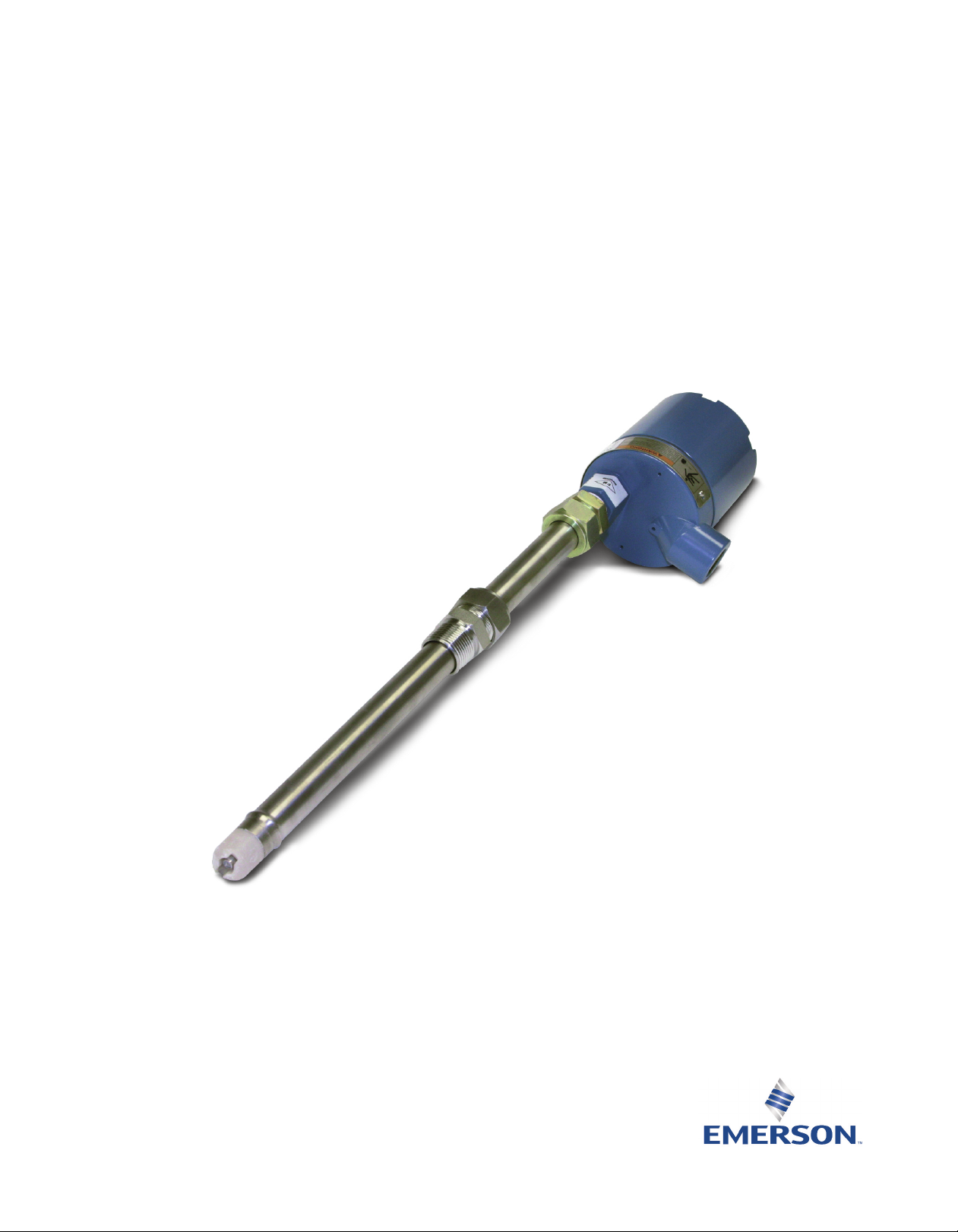
• SMART enabled
• Retractable version allows removal and replacement under pressure without process shutdown.
• Long-life, triple junction reference electrode provides longer service life in applications where
poisoning ions are present.
• Disposable tefzel and titanium design provides maximum chemical resistance and economical advantage where minimum troubleshooting and maintenance downtime are of prime
importance.
1.1 Features and Applications
The Rosemount 385+ Sensor measures the pH or ORP (Oxidation Reduction Potential) of aqueous
solutions in pipelines, open tanks, or ponds. It is suitable for applications where a low cost,
industrial, disposable sensor is required. The combination electrode features a peripheral ceramic
junction. The triple junction reference cell provides longer life in processes containing sugar,
ammonia, chlorides, sulfides or other poisoning ions. The Rosemount 385+ body is constructed of
molded, chemically resistant Tefzel in two standard body versions.
The retraction version is housed in a titanium tube, with a plug-in style surface mount preamplifier
in a weatherproof junction box. It is designed for use with a standard 1-1/2 in. ball valve assembly
for process mounting where a separate sample stream is difficult or impossible to provide. The
entire installation process is accomplished without line depressurization and minimal process fluid
loss. Upon sensor removal, from the ball valve, maintenance and replacement is easy.
The insertion/submersion version has two body configurations: 25 ft (7.6 m) integral cable and
preamplifier; 15 ft (4.5) integral cable for use with remote preamplifier.
Description and Specifications 1
Page 8

Description and Specifications Instruction Manual
March 2017 LIQ-MAN-385+
1.2 Performance and Specifications
able 1-1: Percent linearity over pH
T
pH Range Option 10 Option 11
0-2 pH 94% 94%
2-12 pH 99% 97%
12-13 pH 97% 98%
13-14 pH 92% 98%
Table 1-2: Rosemount 385+ sensor specifications
Measured Range
pH range 0 to 14 pH, GPHT ACCUGLASS
ORP range -1500 mV to 1500 mV
Maximum Pressure at Retraction or Insertion (ball valve version)
542 KPa abs (64 psig)
Maximum Process Pressure and Temperature
790 KPa abs (100 psig) at 100 °C (212 °F)
Temperature Compensation
(pH only) 0 to 100°C (32 to 212°F)
Wetted Materials
Tefzel, titanium, EPDM, 316 SS and Teflon (Code 02), Viton, glass, ceramic and (ORP only) platinum.
Weight/Shipping Weight
Submersion/insertion 1.6 lb/2.8 lb (0.7 kg/1.25 kg)
Retraction 6 lb/11 lb (2.7 kg/5.0 kg)
Ball Valve 5 lb/10 lb (2.25 kg/4.5 kg)
Process Connections
With ball valve 1-1/2 in.
Without ball valve 1 in.
Cable Length
Code 02 Requires interconnecting cable P/N 9200273 (Unprepped) or P/N 23646-01 (Prepped)
Code 03 25 ft. Integral Cable
Code 04 15 ft. Integral Cable
2 Description and Specifications
Page 9

Instruction Manual Description and Specifications
LIQ-MAN-385+ March 2017
1.3 Ordering Information
Table 1-3: Rosemount 385+ ordering information
Model Sensor type
385+ pH/ORP Sensor
Body Configuration
02 Retractable with Sensor Head Junction Box, Preamplifier, and Process Connector
03 Insertion/Submersion with Integral Preamplifier and 25 ft. (7.6m) Cable
04 Insertion/Submersion for use with Remote Preamplifier and 15 ft.
(1) (2)
(2)
Combination Electrode
10 pH - GPLR Glass
11 High pH Glass
12 Platinum ORP
Typical Model Number: 385+-03-10
1. Preamplifier is SMART for pH options only. A standard preamplifier is used with ORP sensors.
2. First time installations require a 1 x 1 inch NPT Process Connector (see accessories).
(1)
Description and Specifications 3
Page 10

Description and Specifications Instruction Manual
March 2017 LIQ-MAN-385+
1.4 Product Certifications
Please see online certificates for further details.
ECEx
I
Sensors without preamp (pH and ORP) – Ex ia IIC T4 Ga (-20°C ≤ Ta ≤ +60°C)
Sensors with preamp (pH only) – Ex ia IIC T4 Ga (-20°C ≤ Ta ≤ +60°C)
Sensors with standard preamp (ORP only) – Ex ia IIC T4 Ga (-20°C ≤ Ta ≤ +80°C) or Ex ia IIC T5 Ga
(-20°C ≤ Ta ≤ +40°C)
Per standards IEC60079-0 : 2011, IEC 60079-11 : 2011
ATEX
Sensors without preamp (pH and ORP) – II 1 G Ex ia IIC T4 Ga (-20 °C ≤ Ta ≤ +60 °C)
Sensors with SMART preamp (pH only ) – II 1 G Ex ia IIC T4 Ga (-20˚C ≤ Ta ≤ +60 °C)
Sensors with standard preamp (ORP only) – II 1 G Ex ia IIC T4 Ga (-20˚C ≤ Ta ≤ +80˚C) or
II 1 G Ex ia IIC T5 Ga (-20˚C ≤ Ta ≤ +40˚C)
Per standards EN 60079-0: 2012+A11:2013, EN 60079-11:2012
FM
See online FM Certificate of Compliance for applicable sensor options:
Intrinsically Safe for use in Class I, II, and III, Division 1, Groups A, B, C, D, E, F, and G; Temperature
Class T6 Ta = -20 °C to +60 °C
Intrinsically Safe for use in Class I, Zone 0, AEx ia IIC T6 Ta = -20 °C to +60 °C
Nonincendive for use in Class I, Division 2, Groups A, B, C, and D; Temperature Class T6 Ta = -20 °C
to +60 °C
Suitable for use in Class II and III, Division 2, Groups E, F, and G; Temperature Class T6 Ta = -20 °C
to +60 °C Hazardous (Classified) Locations
IS/I,II,III/1/ABCDEFG/T6 Ta = 60°C - 1400332; Entity; I/0/AEx ia IIC/T6 Ta = 60 °C - 1400332; Entity;
NI/I/2/ABCD/T6 Ta = 60 °C; S/II,III/2/EFG/T6 Ta = 60 °C
Per standards 3600:1998, 3610:2010, 3611:2004, 3810:2005
CSA
See online CSA Certificate of Compliance for applicable sensor options:
Intrinsically Safe:
Class I, Division 1, Groups ABCD; Class II, Division 1, Groups EFG; Class III; Class I, Division 2, Groups
ABCD; Ambient temperature rating -20 °C to +60 °C; Ex ia IIC; T6
Intrinsically Safe and Non-Incendive:
Class I, Division 1, Groups ABCD; Class II, Division 1, Groups EFG; Class III; Class I, Division 2, Groups
ABCD; Ex ia IIC; T6; Ambient temperature rating -20 °C to +60 °C: (Simple Apparatus)
Per standards C22.2 No. 0-10, C22.2 No. 0.4-M2004, C22.2 No. 94-M1991, C22.2 No. 142 – M1987,
C22.2 No 157 – M1992, CAN/CSA E60079-0:07, CAN/CSA E60079- 11:02, UL50 11th Ed, UL508
17th Ed, UL913 7th Ed, UL 60079-0: 2005, UL 60079-11: 2002
4 Description and Specifications
Page 11

Instruction Manual Installation
LIQ-MAN-385+ March 2017
Section 2: Installation
2.1 Unpacking and Inspection
Inspect the outside of the carton for any damage. If damage is detected, contact the carrier
immediately. Inspect the instrument and hardware. Make sure all items in the packing list are
present and in good condition. Notify the factory if any part is missing.
NOTICE
Save the original packing cartons and materials as most carriers require proof of damage due to mishandling, etc. Also, if it is necessary to return the instrument to the factory, you must pack the instrument in
the same manner as it was received. Refer to Section 6.0 for instructions.
WARNING
Glass electrode must be wetted at all times (in storage and in line) to maximize sensor life.
2.2 Mechanical Installation
The Rosemount 385+ is available in two versions, the retraction version (Code 02) and the
insertion/submersion version (Code 03, & 04). Please refer to the appropriate section below.
2.2.1 Retraction Option (Code option 02)
The Rosemount 385+ sensor may be installed through a weldalet or in a pipe tee or “Y”, as shown
in Figure 2-1, when used with a ball valve. Insert the end of the sensor to a depth sufficient to ensure
that the glass bulb is continuously wetted by the process fluid.
The sensor can also be inserted directly into the process without the use of a ball valve for
applications not requiring continuous operation during sensor maintenance (Figure 2-2).
Allow sufficient room for safe retraction and insertion of the sensor. personnel should have room
for stable footing while performing removal or insertion of the sensor.
The sensor must be mounted within 10-90 degrees of the horizontal with the tip pointed
downward, thus keeping air bubbles out of the pH sensitive glass bulb. Bubbles settled in the glass
bulb disrupt the electrical continuity between the pH sensitive glass and the silver/silver chloride
measuring element.
If the retraction version is to be installed without a ball valve follow the installation procedure for
insertion service (Section 2.2.2). Perform the following steps for sensor installation through a ball
valve:
1. Carefully remove the liquid filled rubber boot which protects the glass electrode and keeps
the liquid junction wet during shipping and storage. Discard the liquid and boot. Make sure
the lubricated O-ring is in place in the groove inside the male connector on the sensor body
(Figure 4-1, item A).
CAUTION
Buffer solution, in the vinyl boot, may cause skin or eye irritation.
Installation 5
Page 12

Installation Instruction Manual
March 2017 LIQ-MAN-385+
2. With the male connector on the sensor’s body, insert the sensor into the ball valve until it
gently touches the closed valve. The molded electrode guard will protect the glass bulb
from breakage.
3. Thread the male connector body tightly into the ball valve assembly. DO NOT tighten the
hex nut on the male connector body; doing so would not allow the sensor to be inserted
through the ball valve.
4. Pull back hard on the sensor assembly, as if trying to remove the sensor, to be certain that
the sensor cannot come free of the ball valve assembly. The built-in retraction stop will butt
against the shoulder of the male connector if properly installed.
CAUTION
The sensor must be captured by the valve assembly and the male connector so that it cannot be blown
free by process pressure if mishandled during insertion or retraction.
5. After confirming that the sensor assembly is properly secured by the valve assembly, the
valve may be opened and the sensor positioned into the process at the desired depth and
orientation.
6. While holding the sensor in position, tighten the hex nut of the male connector to firmly
secure the sensor in place. When the hex nut is tightened, the Teflon ferrule inside the
compression fitting clamps the sensor tube. (See Figure 4-2.)
CAUTION
Over tightening the hex nut may damage the ferrule.
NOTICE
A stainless steel ferrule is available if the TEFLON ferrule does not inadequately grip. When using the
metallic ferrule, care must be taken to avoid over tightening and damaging the sensor tube. If the male
connector leaks during insertion or retraction, replace the O-ring in the male connector.
2.2.2 Submersion/Insertion Option
Code Option -03 & -04). Figure 2-3 and Figure 2-4. The Rosemount 385+ may be installed through
a weldalet or a pipe tee or “Y” when used with a process connector (P/N 23166-00-01).
For submersion service, a process connector (P/N 23166-00-01 or 9510066) may be used with a
water tight 1 in. schedule 80 CPVC or PVDF standpipe conduit. Refer to Figure 2-5. Tapered threads
in plastic tend to loosen after installation. It is therefore recommended that TEFLON tape be used
on the threads and that the tightness of the connection be checked frequently to assure that no
loosening has occurred. The sensor should be installed within 80° of vertical, with the electrode
facing down.
6 Installation
Page 13

Instruction Manual Installation
LIQ-MAN-385+ March 2017
Figure 2-1: Typical Mounting Details-Retraction Version
Figure 2-2: Dimensional Drawing Retraction Version (Code 02)
Installation 7
Page 14

Installation Instruction Manual
March 2017 LIQ-MAN-385+
Figure 2-3: Dimensional Drawing Submersion/Insertion Version (Code -03, -04)
Figure 2-4: Submersion Accessory (Code 03, 04)
8 Installation
Page 15

Instruction Manual Installation
LIQ-MAN-385+ March 2017
igure 2-5: Submersion Installations, Handrail Mounting Assembly (P/N 11275-01)
F
Installations 9
Page 16

Installation Instruction Manual
March 2017 LIQ-MAN-385+
2.3 Electrical Installation
ake electrical connections as shown on Figures 2-6 through 2-14 using the following guidelines:
M
. Pay particular attention to the analyzer or transmitter model number when following
1
details on the wiring diagrams to ensure that the connections are made to the proper
terminals.
2. Use Rosemount custom cable PN 9200273.
3. The maximum distance from the sensor to the analyzer is 15 ft without an integral
preamplifier.
4. Signal cable should be run in a dedicated conduit and should be kept away from AC power
lines.
For additional wiring information on this product, including sensor combinations not shown here,
please refer to the
Figure 2-6: Rosemount 385+-02 Sensor Wiring to Rosemount 5081 Transmitter
Liquid Transmitter Wiring Diagrams.
10 Installation
Page 17

Instruction Manual Installation
LIQ-MAN-385+ March 2017
Figure 2-7: Rosemount 385+-03 Sensor Wiring to Rosemount 5081 Transmitter
Figure 2-8: Rosemount 385+-04 Sensor Wiring to Rosemount 5081 Transmitter
Installation 11
Page 18

Installation Instruction Manual
March 2017 LIQ-MAN-385+
Figure 2-9: Rosemount 385+-02 sensor Wiring to Rosemount 1056/56/1057 Transmitters
Figure 2-10: Rosemount 385+-03 Sensor Wiring to Rosemount 1056/56/1057 Transmitters
12 Installation
Page 19

Instruction Manual Installation
LIQ-MAN-385+ March 2017
Figure 2-11: Rosemount 385+-04 Sensor Wiring to Rosemount 1056/56/1057 Transmitters
Figure 2-12: Wiring Details - Submersion/Insertion (Code 03 & 04)
Installation 13
Page 20

Installation Instruction Manual
March 2017 LIQ-MAN-385+
Figure 2-13: Wiring Rosemount 385+-02 Sensor to Rosemount 1055-11-22-32 through
Remote Junction Box
Figure 2-14: Wiring Retraction Version (Code-02)
14 Installation
Page 21

Instruction Manual Installation
LIQ-MAN-385+ March 2017
Figure 2-15: Wiring Details - Remote J-Box for Extension Cable
Installation 15
Page 22

Installation Instruction Manual
March 2017 LIQ-MAN-385+
Figure 2-16: Wiring Details - Remote J-Box with Preamp
16 Installation
Page 23

Instruction Manual Startup and Calibration
LIQ-MAN-385+ March 2017
Section 3: Startup and Calibration
3.1 Startup
o obtain best accuracy, the sensor must be calibrated as a loop with the transmitter. Please refer
T
to the transmitter manual for proper calibration and setup procedures. Example of 1056 start-up
shown below.
3.2 pH Calibration Using Buffer Solutions or Grab
Samples
The loop may be calibrated with the sensor’s measuring tip submersed in standard pH buffer
solutions (two point calibration) or with a process grab sample of a known pH value (one point
standardization). Please refer to the corresponding transmitter manuals for proper procedures.
3.3 ORP Calibration
An ORP loop is best calibrated using an ORP standard solution.
3.3.1 Quinhydrone Solution
A commonly used ORP standard solution is a saturated quinhydrone solution. This can be made by
simply adding a few quinhydrone crystals to either a 4 pH or a 7 pH buffer. Quinhydrone is only
sightly soluble so only a few crystals will be required. The solution will have a yellow color. The
resulting potentials should be within ±20 millivolts of the value shown in Table 3-1. The ORP value
of saturated quinhydrone solution is not stable over long periods of time and therefore new
solutions should be made each time they are used.
Table 3-1: ORP of Saturated Quinhydrone Solution
pH 4 pH 7
Temperature °C 20 25 30 20 25 30
Millivolt Potential 268 264 260 94 87 80
Startup and Calibration 17
Page 24

Startup and Calibration Instruction Manual
March 2017 LIQ-MAN-385+
3.3.2 Ferric-Ferrous Ammonium Sulfate Solution
Although this solution is not as easy to prepare as the quinhydrone solution in Section 3.3.1, it
offers a much more stable solution which will maintain its millivolt value for approximately one
year when stored in a glass container.
CAUTION
The solution used during the following check is an acid and should be handled with care. Follow the
directions of the acid manu facturer. Wear the proper equip ment. Do not let the solution come in
contact with skin or clothing. If contact with skin is made, immediately rinse with clean
water.
To prepare solution, dissolve 39.2 grams of reagent grade ferrous ammonium sulfate [Fe(SO4) •
(NH)2SO4 • 6H2O] and 48.2 grams of reagent grade ferric ammonium sulfate [FeNH4(SO4)2 •
12H2O] in approximately 700 milliliters of water (distilled water is preferred, but tap water is
acceptable). Slowly and carefully add 56.2 milliliters of concentrated sulfuric acid. Add sufficient
water to bring the total solution volume up to 1,000 milliliters. This solution (ferric-ferrous
ammonium sulfate) will produce a nominal ORP of 476 ±20 mV at 25°C. Some tolerance in mV
values is to be expected due to the rather large liquid reference junction potentials which can arise
when measuring this strongly acidic and concentrated solution. However, if the measuring
electrodes are kept clean and in good operating condition, consistent repeatable calibrations can
be achieved.
NOTICE
Most industrial applications have a number of ORP reactions occurring in sequence or simultaneously.
There can be several components that are oxidized or reduced by the reagents that are used. Theoretically, the ORP potential is absolute because it is the result of the oxidation-reduction equilibrium.
However, the actual measured potential is dependent on many factors, including the condition of the
surface of the ORP platinum electrode. Therefore, the sensor should be allowed 1-2 hours to become
“conditioned” to the stream to be measured when first setting up or after being cleaned.
18 Startup and Calibration
Page 25

Instruction Manual Maintenance
LIQ-MAN-385+ March 2017
Section 4: Maintenance
4.1 Maintenance
he Rosemount 385+ Sensor is a disposal type sensor and therefore requires only periodic cleaning
T
and calibration. If the sensor has failed, it should be discarded and replaced.
4.2 Sensor Removal
Please refer to the appropriate paragraph for instructions regarding removal of the sensor for
periodic maintenance.
4.2.1 Retractable Version (Code-02)
WARNING
System pressure may cause the sensor to blow out with great force unless care is taken during removal.
Make sure the following steps are adhered to.
1. Be certain system pressure at the sensor is below 64 psig (442 kPa) before proceeding with
the retraction. It is also recommended that the personnel wear a face shield and have a
stable footing. Refer to Figure 4-1.
2. Push in on the sensor using the top of the J-box and slowly loosen the hex nut (B) of the
process end male connector (A).
CAUTION
Do not remove nut at this time.
3. When the hex nut is loose enough, slowly ease the sensor back completely until the
retraction stop collar is reached.
CAUTION
Failure to withdraw the sensor completely may result in damage to the sensor when the valve is closed.
4. Close the ball valve slowly. If there is resistance, the valve may be hitting the sensor. Double
check that the sensor has been retracted to the retraction.
WARNING
Before removing the sensor from the ball valve, be absolutely certain that the ball valve is fully closed.
Leakage from the male connector threads may indicate that the male connector is still under pressure.
Leakage through a partially open valve could be hazardous, however with the ball valve closed, some
residual process fluid may leak from the connector's pipe threads.
5. The Male Connector Body (A) may now be completely unthreaded from the reducing
coupling and the sensor removed for servicing stop collar.
CAUTION
If the male connector leaks during insertion or retraction, replace the O-ring (PN 9550099) in the male
connector A.
Maintenance 19
Page 26

Maintenance Instruction Manual
March 2017 LIQ-MAN-385+
4.2.2 Insertion/Submersion Version (Code -03 and -04 )
WARNING
efore removing the sensor, be absolutely certain that the process pressure is reduced to 0 psig and
B
the process temperature is lowered to a safe level!
Remove the sensor from process for cleaning, calibration or replacement.
4.3 pH Electrode Cleaning
If the electrode is coated or dirty, it may be cleaned as follows:
1. Remove the sensor from process as instructed in Section 4.2.
2. Wipe the glass bulb with a soft, clean, lint free cloth or tissue. If this does not remove the
dirt or coating, proceed to step 3. If the sensor appears to be clean, go to step 5.
3. Wash the glass bulb in a strong detergent solution and thoroughly rinse with tap water. If
the bulb still appears to have a coating, proceed to step 4.
CAUTION
The solution used in the following step is an acid and should be handled with care. Follow the directions
of the acid manufacturer. Wear the proper protective equipment. Do not let the solution come in
contact with skin or clothing. If contact with the skin is made, immediately rinse with clean water.
4. Following the caution above, wash the glass bulb in dilute 5% hydrochloric acid solution
and then rinse it thoroughly in tap water. Replace the sensor if it cannot be cleaned. If the
glass bulb appears clean, proceed to step 5.
5. Buffer calibrate the sensor (Refer to Section 3.0). If the sensor appears to respond
sluggishly to pH change, soaking it overnight in a weak acid solution (5% hydrochloric acid)
may improve its response. Be sure to follow the CAUTION above and to rinse the sensor’s
tip thoroughly with tap water. If the sensor will not calibrate, it must be replaced.
4.4 Platinum Electrode Cleaning
Remove any film or dirt by wiping the electrodes platinum band with a clean, lint free, cloth. If
needed, a strong detergent should be used to remove any remaining dirt or film.
Platinum electrodes can become poisoned by cyanide or sulfide compounds. However, processes
involving these compounds (such as cyanide destruction) will destroy all the cyanides or sulfides
before they can react with the platinum.
Should poisoning occur, the electrode can be restored to normal operation by polishing the
platinum (metallic) surface with moistened baking soda (after a strong detergent wash to remove
any film on the platinum surface).
20 Maintenance
Page 27

Instruction Manual Maintenance
LIQ-MAN-385+ March 2017
4.5 Sensor Tube Replacement (Code -02)
Replacement of the retraction versions sensor tube assembly involves the removal and installation
of two sets of male connectors; one at the process end of the sensor, and the other at the junction
ox end. Refer to Section 4.2 for proper removal of the sensor from process.
b
1. Remove sensor from process before proceeding. The junction box with attached male
connector must be recovered from the old sensor for reuse. Unscrew the junction box cover
and set aside. Disconnect electrical connections from printed circuit board inside junction
box. Disconnect BNC connector to preamp. Unscrew hex nut (D) from male connector
body (C). Separate junction box from used sensor. Set aside.
2. Pry off split ferrule from sensor and set aside for reuse. Remove hex nut (D) and set aside
for reuse. Check that the internal O-ring is in place in the male connector body (C) attached
to the junction box.
3. Remove hex nut (B) from male connector body (A) at process end of sensor and set aside.
Slide the Teflon ferrule and the male connector off sensor in the direction of junction box
and set aside. Discard sensor tube.
NOTICE
If stainless steel ferrule was used, male connector body (A) will have to be dis carded with the sensor
tube.
4. Discard used O-ring from male connector body (A). Coat new O-ring with a thin film of the
O-ring lubricant provided. Position it in the machined O-ring groove in place of the
discarded O-ring.
CAUTION
Make sure lubricant does not contact any part of the sensor tip particularly the glass bulb.
5. Cover the 1in. MNPT pipe threads of the male connector body (A) with TEFLON tape (not
provided) to protect them from galling during reinstallation.
6. Pass the wires from the new sensor through the process end male connector (A). Make
sure that the beveled edge of the ferrule faces the process end of the sensor. Snug the hex
nut (B) to keep it in place. Do not tighten down fully on the hex nut at this time.
7. Pass the wires from the new sensor through the hex nut (D), the split ferrule (from the old
sensor), male connector body (C), O-ring, and through the junction box from the “neck”
opening and out to the printed circuit board in the junction box. Butt the ferrule’s beveled
edge and the sensor tube against the junction male connector (C). Screw the hex nut (D)
by hand until the tube is “locked” into the male connector body. Make sure that the male
connector body (C) is sufficiently tightened. The sensor will “click” into place by pulling
the sensor tube away from the junction box, but will not move from side to side or pull
clear of the male connector. If the sensor tube is correctly attached to the junction box,
wrench tighten hex nut (D) on male connector body (C) (see Figure 4-1). Do not put the
sensor tube in a vise or use a pipe wrench to tighten the hardware as these will damage
the sensor. If sensor tube is not correctly attached to the junction box, loosen hex nut (D)
and repeat.
Maintenance 21
Page 28

Maintenance Instruction Manual
March 2017 LIQ-MAN-385+
8. Connect the sensor wires to the terminals on the printed circuit board in the junction box
n the manner recommended on the junction box cover, or see Figure 2-4. Reattach the
i
BNC connector to the preamp. Screw on the cover of the junction box.
9. Insert the sensor in the process fitting. Stop it against the closed ball valve. Slide the
processend male connector down the sensor tube to mate with the process fitting. Tighten
the male connector into the process fitting.
10. Pull back hard on the sensor assembly, as if trying to remove the sensor, to be certain that
the sensor cannot come free from the valve assembly and male connector. The built-in
retraction stop collar at the end of the sensor will butt against the shoulder of the male
connector.
11. Open ball valve and position the sensor at the desired insertion depth and orientation.
Using a crescent or open end wrench, tighten the hex nut (B) to secure the sensor in place.
NOTICE
A stainless steel ferrule is available if the TEFLON ferrule does not adequately grip. When using the
metallic ferrule, be careful and avoid over tightening. This can damage the sensor tube.
CAUTION
If the male connector leaks during insertion or retraction, replace the O-ring (PN 9550099) in the male
connector body (A).
If the sensor is to be stored, the rubber boot should be filled with 7 pH buffer solution and replaced
on sensor tip until ready to use.
Figure 4-1: Sensor Tube Replacement
22 Maintenance
Page 29

Instruction Manual Maintenance
LIQ-MAN-385+ March 2017
Figure 4-2: Male Connector Tightening Diagram
Maintenance 23
Page 30

Maintenance Instruction Manual
March 2017 LIQ-MAN-385+
24 Maintenance
Page 31

Instruction Manual Diagnostics and Troubleshooting
LIQ-MAN-385+ March 2017
Section 5: Diagnostics and Troubleshooting
5.1 Model 54/3081 pH Diagnostics
The Models 54 and 54e Transmitters and Models 3081, 4081, and 5081 pH Transmitters
automaically search for fault conditions that would cause an error in the measured pH value. Refer
to the respective manual for a complete description of the transmitter’s fault conditions.
5.2 Troubleshooting
Table 5-1, below, lists the diagnostic messages that indicate a possible sensor problem. A more
complete description of the problem and a suggested remedy corresponding to each message is
also listed.
Table 7-1: Troubleshooting
Note: For any repair or warranty inquiries please contact our Customer Care group.
Diagnostics and Troubleshooting 25
Page 32

Diagnostics and Troubleshooting Instruction Manual
March 2017 LIQ-MAN-385+
5.3 Rosemount 1056/1057 SMART pH Diagnostics
Rosemount 1056 and 1057 transmitters automatically search for SMART sensors. Once the SMART
sensor is detected, 385+ (-03), and communication is established the start-up, screen will appear,
figure 5-1. Start-up and calibration of pH/ORP are described on page 16. Up to five (5) calibration
ata sets can be found under DIAG/sensorX/calibration history, see figure 5-2.
d
Figure 5-1: SMART start-up screen
Figure 5-2: Calibration History menu on Rosemount 1056
The calibration data contain slope, offset, temperature, method of calibration (page 16), glass
impedance, reference impedance and time stamp between the calibration, figure 5-3. Advanced
diagnostic data can be used for preventive maintenance, replacement and timely troubleshoot.
Figure 5-3: Calibration History screen
26 Diagnostics and Troubleshooting
Page 33

Instruction Manual Diagnostics and Troubleshooting
LIQ-MAN-385+ March 2017
Please refer to the corresponding installment manual for detailed description.
The factory calibration data can be found on the bottom of Calibration History menu figure 5-2. Use
key-pad to scroll down to the bottom, find Factory Cal. line and press enter. The factory calibration
screen will appear, figure 5-4. It contains the serial number of the sensor, slope, offset, temperature
ffset, glass impedance and reference inductance value. It's possible to retore the calibration
o
settings to factory default. Please, refer to corresponding instrument manual for correct
procedure.
Figure 5-4: Factory Calibration
Diagnostics and Troubleshooting 27
Page 34

Diagnostics and Troubleshooting Instruction Manual
March 2017 LIQ-MAN-385+
28 Diagnostics and Troubleshooting
Page 35

Instruction Manual Accessories
LIQ-MAN-385+ March 2017
Section 6: Accessories
6.1 Accessories
Table 6-1: Accessories for Rosemount 385+ sensor
Part Number Description
11275-01 Handrail mounting assembly (Code 03, 04 only)
23550-00 Remote J-Box without preamplifier (Code 02, 03 only)
23555-00 Remote J-Box with preamplifier, (Code 04 only)
23166-00 Process connector, 316SS, insertion/submersion 1 in. MNPT (Code 02, 03, 04)
23166-01 Process connector, titanium, insertion/submersion 1 in. MNPT (Code 02, 03, 04)
9510066 Process connector, Nylon, submersion only, 1 in. MNPT (Code 03, 04)
9210012 Buffer solution, 4.01 pH, 16 oz
9210013 Buffer solution, 6.86 pH, 16 oz
9210014 Buffer solution, 9.18 pH, 16 oz
12707-00 Jet Spray Cleaner for submersion service
23566-00 Sensor Tube, pH, Pt 100, Titanium, Low Resistance Glass
23566-01 Sensor Tube, pH, Pt 100, Titanium, High pH
23566-02 Sensor Tube, ORP, Pt 100, Titanium, General Purpose
23240-00 Ball Valve Assembly 316 Stainless Steel
23646-01 Cable, 12 Conductor, Shielded, Prepped
23557-00 Preamplifier, J-box
33046-00 Ferrule, 1 in. 316 SS, Split
9310096 Nut, Swage, 1 in. 316 SS
9310100 Ferrule, 1 in. TEFLON
9550099 O-ring, 2-214, VITON
Accessories 29
Page 36

Accessories Instruction Manual
March 2017 LIQ-MAN-385+
30 Accessories
Page 37

Instruction Manual EC Declaration of Conformity
LIQ-MAN-385+ March 2017
EC Declaration of Conformity
Note: Please see website for most recent Declaration.
EC Declaration of Conformity 31
Page 38

EC Declaration of Conformity Instruction Manual
March 2017 LIQ-MAN-385+
32 EC Declaration of Conformity
Page 39

ANY FM APPROVED
ASSOCIATED APPARATUS
HAVING ENTITY PARAMETERS
NO
N-
H
AZARDOUS
(UNCLASSIFIED)
AREA
CLASS I, II, III, DIVISION 1, GROUPS A-G
T6 Ta = 60°C
SENSOR
ENTITY PARAMETERS
Ui = 13.1U, Ii = 358mA
Pi = 698 mW
Ci = 0.967 µF, Li = 0.1mH
1. NO REVISION TO THIS DRAWING IS PERMITTED WI THOUT
FM APPROVAL.
2. U
max
> U
t
; I
max
> I
t
; (C
i
OF ALL LOOPS + C CABLE) < C
a
;
(L
i
OF ALL LOOPS + L CABLE) < L
a
, P
max
OR P
i
> P
0.
3. SINGLE MULTI-CHANNEL
IS BARRIER OR APPARATUS MUST BE FM APPROVED,
4. SINGLE MULTI-CHANNEL
IS BARRIER OR APPARATUS MANUFACTURE'S
CONTROL DRAWI NGS MUST BE FOLLOWED WHEN INSTALLING THE SYSTEM.
IS BARRIER OR EQUI PMENT MAY BE INSTALLED WITHIN THE HAZARDOUS
(CLASSIFIED) LOCATION FOR WHICH IT IS APPROVED
.
5. INSTALLATION MUST BE IN ACCORDANCE WITH ARTICL
E 500 OF THE NEC
(ANSI/NFPA 70) AND ANSI/ISA RP 12.6.
WARNING: SUBSTITUTION OF COMPONENTS MAY IMPA
IR INTRINSIC SAFETY.
6. pH & AMPEROMETRIC SENSORS WITHOUT PREAMPS ARE SIMPLE APPARATUS.
ZON E
ZONE 0
7. CONTROL EQUIPMENT CONNECTED TO THE ASSOCIATED APPARATUS MUST
NOT USE OR GENERATE MORE THAN 250V.
RESISTANCE BETWEEN INTRINSICALLY SAFE GROUND AND EARTH GROUND
MUST BE LESS THAN OR EQUAL TO 1 OHM.
ANY
FM APPROVED TRANSMITTER FOR
DIVISION 1 WI TH INTRINSICALLY SAFE
OUTPUT PARAMETERS. THIS
FM
APPROVED DEVICE MUST BE INSTALLED
PER ITS INSTALLATION DRAWING.
FM
APPROVED EQUIPMENT (MAY BE
MULTIPLE DEVICES, NUMBER IS LIMITED
BY REQUIREMENTS TO MEET ALL OTHER
IS REQUIREMENTS FOR THE NETWORK)
WITH EQUIVALENT HAZARDOUS AREA
APPROVALS.
H
AZA RDOUS
(CL ASSI
F
IED)
AREA
INTRISICALLY SA FE
9. pH/ORP SENSOR MODELS THAT MAY CONTAIN THE PREAMPLIFIER:
3900/VP
3500/VP
3300HT/VP
3400HT/VP
396/VP
396R/VP
396P/VP
398R/VP
399/VP
389/VP
385/385+
10. WARNING: TO PREVENT IGNITION OF FLAMMABLE OR COMBUSTIBLE
ATM OSPHERES, DISCONNECT POWER BEFORE SERVIC
ING.
11. THE ENTI TY CONCEPT ALLOWS INTECONNECTION OF INTRINSICALLY SAFE
APPARATUS WITH ASSOCIATED APPARATUS WHEN THE FOLLOWING IS TRUE:
U
i
> U
o;
I
i
> I
o;
P
i
> P
o;
C
o
> C
i
+ C CABLE; L
o
> L
i
+ L CABLE.
12. COPY REVI SIONS TO 1400332 TO pH/ORP SHIPPING MANUALS.
13 Ci INCLUDES THE CAPACITANCE OF 500 FEET OF SENSOR CABLE.
13
DWG NO.
1400332
8.
Instruction Manual FM Installation
LIQ-MAN-385+ March 2017
Intrisicallly Safe Sensor Installation Drawing - FM
FM Installation 33
Page 40

LIQ-MAN-385+
Rev. J
March 2017
www.Emerson.com/RosemountLiquidAnalysis
Youtube.com/user/Rosemount
Twitter.com/Rosemount_News
Emerson
8200 Market Blvd.
Chanhassen, MN 55317,
USA
Tel +1 800 999 9307
Fax +1 952 949 7001
Liquid.CSC@Emerson.com
Analyticexpert.com
facebook.com/Rosemount
©2017 Emerson. All rights reserved.
The Emerson logo is a trademark and service mark of Emerson Electric Co. Rosemount is a mark of
one of the Emerson family of companies. All other marks are the property of their respective
owners.
The contents of this publication are presented for information purposes only, and while effort has
been made to ensure their accuracy, they are not to be construed as warranties or guarantees,
express or implied, regarding the products or services described herein or their use or applicability.
All sales are governed by our terms and conditions, which are available on request. We reserve the
right to modify or improve the designs or specifications of our products at any time without notice.
 Loading...