

Page 1
Instruction Manual
IQ-MAN-PERpH-X
L
April 2017
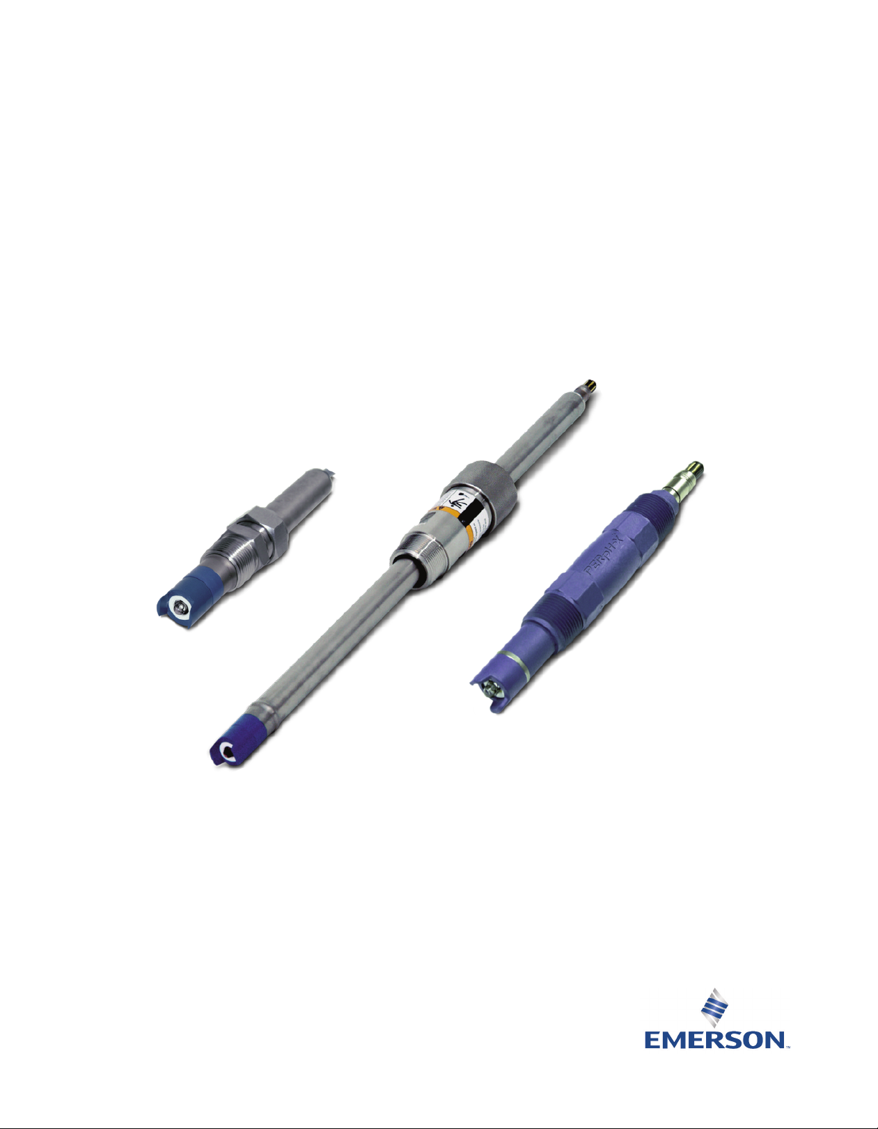
Rosemount™3300HT/3300HTVP/3400HT/
3400HTVP/3500P/3500VP
PERpH-X High Performance pH/ORP Sensors
Rev. J
Page 2

asgkas
h
Page 3

Essential Instructions
Read this page before proceeding!
Emerson designs, manufactures and tests its products to meet many national and international stan-
dards. Because these sensors are sophisticated technical products, you MUST properly install, use,
nd maintain them to ensure they continue to operate within their normal specifications. The
a
following instructions MUST be adhered to and integrated into your safety program when installing,
using, and maintaining Rosemount products. Failure to follow the proper instructions may cause
any one of the following situations to occur: loss of life; personal injury; property damage; damage
to this sensor; and warranty invalidation.
• Read all instructions prior to installing, operating, and servicing the product.
• If you do not understand any of the instructions, contact your Emerson representative for
clarification.
• Follow all warnings, cautions, and instructions marked on and supplied with the product.
• Inform and educate your personnel in the proper installation, operation, and maintenance
of the product.
• Install your equipment as specified in the Installation Instructions of the appropriate
Instruction Manual and per applicable local and national codes. Connect all products to
the proper electrical and pressure sources.
• To ensure proper performance, use qualified personnel to install, operate, update,
program, and maintain the product.
• When replacement parts are required, ensure that qualified people use replacement parts
specified by Emerson. Unauthorized parts and procedures can affect the product's
performance, place the safe operation of your process at risk, and VOID YOUR WARRANTY.
Third-party substitutions may result in fire, electrical hazards, or improper operation.
• Ensure that all equipment doors are closed and protective covers are in place, except when
maintenance is being performed by qualified persons, to prevent electrical shock and
personal injury.
The information contained in this document is subject to change without notice.
CAUTION
Sensor/Process Application Compatibility
The wetted sensor materials may not be compatible with process composition and operating
conditions. Application compatibility is entirely the responsibility of the user.
WARNING
Before removing the sensor, be absolutely certain that the process pressure is reduced to 0 psig and
the process temperature is lowered to a safe level!
CAUTION
Special Conditions for Safe Use
1. All pH/ORP sensors have a plastic enclosure which must only be cleaned with a damp cloth to avoid
the danger due to a build up of an electrostatic charge.
2. All pH/ORP sensor models are intended to be in contact with the process fluid and may not meet the
500V r.m.s. a.c. test to earth.
This must be taken into consideration at installation.
Page 4

About This Document
This manual contains instructions for installation and operation of the Rosemount 3300HT/3300HTVP/
3400HT/3400HTVP/3500P/3500VP.
The following list provides concerning all revisions of this document.
Rev. Level Date Notes
J 04/2017 Updated information with new Emerson Style Guidelines, Updated
Ordering Information, Specifications, and Wiring Diagrams. Added
Accessories Information, EC Declaration of Conformity and
FM Installation Drawings.
Page 5

Instruction Manual Table of Contents
LIQ-MAN-PERpH-X April 2017
Contents
Section 1: Specifications
1.1 Specifications ......................................................................................................1
1.2 Product Certifications ..........................................................................................3
1.3 Ordering Information...........................................................................................4
Section 2: Installation
2.1 Storage................................................................................................................7
2.2 Installation...........................................................................................................7
2.3 Retraction with Kit P/N 23240-00 ......................................................................16
2.4 Electrical Installation..........................................................................................17
Section 3: Startup and Calibration
3.1 Electrode Preparation .......................................................................................21
3.2 pH Sensor Calibration ........................................................................................21
3.3 Recommended pH Sensor Standardization ........................................................21
Section 4: Maintenance
4.1 Electrode Cleaning.............................................................................................23
4.2 Reference Junction Replacement and Sensor Electrolyte Recharge.....................23
Section 5: Accessories
5.1 Accessories........................................................................................................25
EC Declaration of Conformity.............................................................................27
Intrisicallly Safe Sensor Installation Drawing - FM ................................29
Table of Contents i
Page 6

Table of Contents Instruction Manual
April 2017 LIQ-MAN-PERpH-X
ii Table of Contents
Page 7

Instruction Manual Specifications
LIQ-MAN-PERpH-X April 2017
Section 1: Specifications
1.1 Specifications
Table 1-1: Percent linearity over pH
pH Range HT Series
0-2 pH 94%
2-12 pH 99%
12-13 pH 97%
13-14 pH 92%
Table 1-2: Rosemount 3300HT/3300HTVP sensor specifications
Measured Range
pH range 0 to 14 pH
ORP range -1500 mV to 1500 mV
Operating Temperature
Without Preamplifier 41 to 311 °F (5 to 155 °C)
With Preamplifier up to 212 °F (100 °C)
Storage Temperature
14 to 138 °F (-10 to 70 °C)
Maximum Process Pressure
400 psig (2859 kPa [abs])
CRN Rating: 200 psig at room temperature
Wetted Materials
Titanium, Ryton, Teflon, Glass, and User Specified O-ring Material (EPDM, Viton or Kalrez)
Reference Electrode
Double junction with replaceable process side electrolyte and Teflon junction
Temperature Sensor
Pt-100 RTD
Process Connections
Must use 1 in. compression process connector (P/N 23166-00 or 23166-01)
Weight/Shipping Weight
1 lb/2 lb (0.5 kg/0.9 kg)
Cable Length
15 ft. integral cable (Rosemount 3300HT) or VP8 Cable for Rosemount 3300HTVP (sold separately)
Specifications 1
Page 8

Specifications Instruction Manual
April 2017 LIQ-MAN-PERpH-X
Table 1-3: Rosemount 3400HT/3400HTVP sensor specifications
Measured Range
pH range 0 to 14 pH
ORP range -1500 mV to 1500 mV
perating Temperature
O
Without Preamplifier 41 to 311 °F (5 to 155 °C)
ith Preamplifier
W
Storage Temperature
14 to 138 °F (-10 to 70 °C)
Maximum Process Pressure
400 psig (2859 kPa [abs])
CRN Rating: 200 psig at room temperature
Wetted Materials
Titanium, Ryton, Teflon, Glass, and User Specified O-ring Material (EPDM, Viton or Kalrez)
Reference Electrode
Double junction with replaceable process side electrolyte and Teflon junction
Temperature Sensor
Pt-100 RTD
Process Connections
Must use 1 in. compression process connector (P/N 23166-00 or 23166-01)
Can be inserted through a ball valve
Weight/Shipping Weight
21 inch Sensor 2 lbs/3 lbs (0.9 kg/1.4 kg)
36 inch Sensor 3 lbs/4 lbs (1.4 kg/1.8 kg)
p to 293 °F (145 °C)
u
Table 1-4: Rosemount 3500P/3500VP sensor specifications
Measured Range
pH range 0 to 14 pH
ORP range -1500 mV to 1500 mV
Operating Temperature
41 to 248 °F (5 to 120 °C)
Storage Temperature
14 to 122 °F (-10 to 50 °C)
Maximum Process Pressure
100 psig (790 kPa [abs])
CRN Rating: 40 psig at room temperature
Wetted Materials
Titanium, Ryton, Teflon, Glass, and User Specified O-ring Material (EPDM, Viton or Kalrez)
Reference Electrode
Double junction with replaceable process side electrolyte and Teflon junction
Temperature Sensor
Pt-100 RTD
Process Connections
1in. MNPT Front and Rear facing threads
Weight/Shipping Weight
21 inch Sensor 2 lbs/3 lbs (0.9 kg/1.4 kg)
2 Specifications
Page 9

Instruction Manual Specifications
LIQ-MAN-PERpH-X April 2017
1.2 Product Certifications
lease see online certificates for further details.
P
IECEx
Sensors without preamp – Ex ia IIC T4 Ga (-20 °C ≤ Ta ≤ +60°C)
Sensors with SMART preamp (pH only) – Ex ia IIC T4 Ga (-20°C ≤ Ta ≤ +60°C)
Sensors with standard preamp (ORP only) – Ex ia IIC T4 Ga (-20°C ≤ Ta ≤ +80°C) or
Ex ia IIC T5 Ga (-20°C ≤ Ta ≤ +40°C)
Per standards IEC60079-0 : 2011, IEC 60079-11 : 2011
ATEX
Sensors without preamp – II 1 G Ex ia IIC T4 Ga (-20˚C ≤ Ta ≤ +60˚C)
Sensors with SMART preamp (pH only) – II 1 G Ex ia IIC T4 Ga (-20˚C ≤ Ta ≤ +60˚C)
Sensors with standard preamp (ORP only) – II 1 G Ex ia IIC T4 Ga (-20˚C ≤ Ta ≤ +80˚C) or
II 1 G Ex ia IIC T5 Ga (-20˚C ≤ Ta ≤ +40˚C)
Per standards EN 60079-0: 2012+A11:2013, EN 60079-11:2012
FM
See online FM Certificate of Compliance for applicable sensor options:
Intrinsically Safe for use in Class I, II, and III, Division 1, Groups A, B, C, D, E, F, and G; Temperature
Class T6 Ta = -20˚C to +60˚C
Intrinsically Safe for use in Class I, Zone 0, AEx ia IIC T6 Ta = -20˚C to +60˚C
Nonincendive for use in Class I, Division 2, Groups A, B, C, and D; Temperature Class T6 Ta = -20˚C
to +60˚C
Suitable for use in Class II and III, Division 2, Groups E, F, and G; Temperature Class T6 Ta = -20˚C
to +60˚C Hazardous (Classified) Locations
IS/I,II,III/1/ABCDEFG/T6 Ta = 60°C - 1400332; Entity; I/0/AEx ia IIC/T6 Ta = 60°C - 1400332; Entity;
NI/I/2/ABCD/T6 Ta = 60°C; S/II,III/2/EFG/T6 Ta = 60°C
Per standards 3600:1998, 3610:2010, 3611:2004, 3810:2005
CSA
See online CSA Certificate of Compliance for applicable sensor options:
Sensors with preamp – Intrinsically Safe:
Class I, Division 1, Groups ABCD; Class II, Division 1, Groups EFG; Class III; Class I, Division 2, Groups
ABCD; Ambient temperature rating -20˚C to +60˚C; Ex ia IIC; T6
Sensors without preamp – Intrinsically Safe and Non-Incendive:
Class I, Division 1, Groups ABCD; Class II, Division 1, Groups EFG; Class III; Class I, Division 2, Groups
ABCD; Ex ia IIC; T6; Ambient temperature rating -20˚C to +60˚C: (Simple Apparatus)
Per standards C22.2 No. 0-10, C22.2 No. 0.4-M2004, C22.2 No. 94-M1991, C22.2 No. 142 – M1987,
C22.2 No 157 – M1992, CAN/CSA E60079-0:07, CAN/CSA E60079 - 11:02, UL50 11th Ed, UL508
17th Ed, UL913 7th Ed, UL 60079-0: 2005, UL 60079-11: 2002
Specifications 3
Page 10

Specifications Instruction Manual
April 2017 LIQ-MAN-PERpH-X
1.3 Ordering Information
able 1-5: Rosemount 3300HT sensor ordering information
T
Model Sensor type
3300HT pH/ORP Sensor
Measuring Electrode
10 pH - GPHT Glass
12 ORP
O-ring Material
30 EPDM
31 Viton
32 Kalrez
Typical Model Number: 3300HT-10-30
Table 1-6: Rosemount 3300HTVP sensor ordering information
Model Sensor type
3300HTVP pH/ORP Sensor
Measuring Electrode
10 pH - GPHT Glass
12 ORP
O-ring Material
30 EPDM
31 Viton
32 Kalrez
Preamplifier Option
_ No selection
70 SMART Preamplifier
Typical Model Number: 3300HTVP-10-30-70
(1)
1. Only available if selected with option 10.
4 Installation
Page 11

Instruction Manual Specifications
LIQ-MAN-PERpH-X April 2017
able 1-7: Rosemount 3400HT sensor ordering information
T
Model Sensor type
3300HTVP pH/ORP Sensor
easuring Electrode
M
10 pH - GPHT Glass
12 ORP
Sensor Length
21 21 in. Titanium Tube
22 36 in. Titanium Tube
O-ring Material
30 EPDM
31 Viton
32 Kalrez
Cable Length
61 9.5 in. cable without BNC
62 15 ft. cable without BNC
Typical Model Number: 3400HT-10-21-30-62
(1)
(2)
1. For use with sensor head junction boxes.
2. For wiring directly to transmitter or junction box.
Table 1-7: Rosemount 3400HTVP sensor ordering information
Model Sensor type
3400HT pH/ORP Sensor
Measuring Electrode
10 pH - GPHT Glass
12 ORP
Sensor Length
21 21 in. Titanium Tube
22 36 in. Titanium Tube
O-ring Material
30 EPDM
31 Viton
32 Kalrez
Preamplifier Option
_ No Selection
70 SMART Preamplifier
Typical Model Number: 3400HTVP-10-21-30-70
(1)
1. Only available if selected with option 10.
Installation 5
Page 12

Specifications Instruction Manual
April 2017 LIQ-MAN-PERpH-X
able 1-7: Rosemount 3500P sensor ordering information
T
Model Sensor type
3500P pH/ORP Sensor
lectrolyte Selection
E
BF Bio-Film Resistant
HT High Temperature
MR Metal Resistant
OR Oil Resistant
PR Poisoning Resistant
R
S
Preamplifier/Cable
01 Preamplifier with 25 ft.
02 No Preamplifier with 15 ft. Cable
Measuring Electrode Type
10 pH – GPHT Glass
12 ORP
Reference Type
21 Double Junction Reference
O-ring Material
30 EPDM
31 Viton
32 Kalrez
Typical Model Number: 3500P-HT-01-10-21-30
caling Resistant
S
(1)
1. Preamplifier is SMART if selected with option 10. Preamplifier is standard if selected with option 12.
Table 1-7: Rosemount 3500VP sensor ordering information
Model Sensor type
3500VP pH/ORP Sensor
Electrolyte Selection
BF Bio-Film Resistant
HT High Temperature
MR Metal Resistant
OR Oil Resistant
PR Poisoning Resistant
SR Scaling Resistant
Preamplifier/Cable
01 Preamplifier
02 No Preamplifier
(1)
Measuring Electrode Type
10 pH – GPHT Glass
12 ORP
Reference Type
21 Double Junction Reference
O-ring Material
30 EPDM
31 Viton
32 Kalrez
Typical Model Number: 3500VP-HT-01-10-21-30
1. Preamplifier is SMART if selected with option 10. Preamplifier is standard if selected with option 12.
6 Installation
Page 13

Instruction Manual Installation
LIQ-MAN-PERpH-X April 2017
Section 2: Installation
2.1 Storage
1. It is recommended that electrodes be stored in their original shipping containers
until needed.
2. Do not store Rosemount 3500P at temperatures below 14 °F (-10 °C). Rosemount 3300HT,
3300HTVP, 3400HT, and 3400HTVP below 23 °F (-5 °C).
3. Electrodes should be stored with a protective cap containing KCl solution.
4. For overnight storage, immerse the sensor in tap water or 4 pH buffer solution.
5. A pH glass electrode has a limited shelf life of one year.
2.2 Installation
For sensor dimensions, see Figure 2-1 to Figure 2-3.
For sensor orientation and installation, see Figure 2-4 to Figure 2-13.
For wiring, see Figure 2-14 to Figure 2-17.
Figure 2-1: Example of sensor tube replacement
Installation 7
Page 14

Installation Instruction Manual
April 2016 LIQ-MAN-PERpH-X
Figure 2-2: Rosemount 3300HT and 3300HTVP sensor dimensional drawing
8 Installation
Page 15

Instruction Manual Installation
LIQ-MAN-PERpH-X April 2017
Figure 2-3: Rosemount 3400HT and 3400HTVP sensor dimensions with optional Ball
Valve PN 23240-00
Installation 9
Page 16

Installation Instruction Manual
April 2017 LIQ-MAN-PERpH-X
Figure 2-4: Rosemount 3400HT and 3400HTVP sensor dimensions with optional Ball
Valve PN 23765-00
10 Calibration and Maintenance
Page 17

Instruction Manual Installation
LIQ-MAN-PERpH-X April 2017
igure 2-5: Rosemount 3300HT and 3300HTVP flow through and insertion installation.
F
1½ in. pipe Tee (PN 2002011) with 1 in. threaded connections.
Note: The sensor must be mounted at least 10° above the horizon.
Figure 2-6: Rosemount 3500P and 3500VP sensor dimensional drawing
Calibration and Maintenance 11
Page 18

Installation Instruction Manual
April 2017 LIQ-MAN-PERpH-X
Figure 2-7: Rosemount 3500P AND 3500VP Jet Spray Cleaner (PN 12707-00) for
Submersion Installation.
This accessory is especially useful for keeping the sensor clean in dirty ponds or tanks. It can
be mounted using the Handrail Mounting Assembly or a similar submersion accessory.
Figure 2-8: Rosemount 3500P and 3500VP flow through installation
12 Installation
Page 19

Instruction Manual Installation
LIQ-MAN-PERpH-X April 2017
Figure 2-9: Rosemount 3500P or 3500VP for Submersion Installation using the
Handrail Mounting Assembly (PN 11275-01)
All parts shown are supplied. Sensor sold separately.
Installation 13
Page 20

Installation Instruction Manual
April 2017 LIQ-MAN-PERpH-X
igure 2-10: Rosemount 3400HT and 3400HTVP mounting details – retraction version
F
Figure 2-11: Exploded view of 1½ in. ball valve kit PN 23240-00 used with process connector
PN 23166-00 (or PN 23166-01).
Ball valve kit includes 11/2" x 1" reducer, 11/2" close nipple, and 11/2" ball valve.
Figure 2-12: Exploded view of 1¼ in. ball valve kit (PN 23765-00)
14 Installation
Page 21

Instruction Manual Installation
LIQ-MAN-PERpH-X April 2017
igure 2-13: Rosemount 3300HT or 3300HTVP typical submersion installation
F
Installation 15
Page 22

Installation Instruction Manual
April 2017 LIQ-MAN-PERpH-X
2.3 Retraction with Kit P/N 23240-00
WARNING
ystem pressure may cause the sensor to blow out with great force unless care is taken during removal.
S
2.3.1 Rosemount 3400HT/3400HTVP-21 (21 in. Tube)
Be certain system pressure at the sensor is below 64 psig (542 kPa) before proceeding with the
retraction. It is also recommended that the personnel wear a face shield and have a stable footing.
Refer to Figure 2-1. Push in on the sensor end or the top of the J-box and slowly loosen the hex nut
(B) of the process end male connector (A).
2.3.2 Rosemount 3400HT/3400HTVP-25 (36 in. Tube)
1. Be certain that pressure at the sensor is below 35 psig (343 KPa) before proceeding with
the retraction. It is also recommended that the personnel wear a face shield and have a
stable footing. Refer to Figure 2-1. Push in on the sensor end or the top of the J-box and
slowly loosen the hex nut (B) of the process end male connector (A).
CAUTION
Do not remove nut at this time.
2. When the hex nut is loose enough, slowly ease the sensor back completely until the
retraction stop collar is reached.
NOTICE
Failure to withdraw the sensor completely may result in damage to the sensor when the valve is closed.
3. Close the ball valve slowly. If there is resistance, the valve may be hitting the sensor. Double
check that the sensor has been retracted to the retraction stop collar.
WARNING
Before removing the sensor from the ball valve, be absolutely certain that the ball valve is fully closed.
Leakage from the male connector threads may indicate that the male connector is still under pressure.
Leakage through a partially open valve could be hazardous, however with the ball valve closed, some
residual process fluid may leak from the connector's pipe threads.
4. The male connector body (A) may now be completely unthreaded from the reducing
coupling and the sensor removed for servicing.
NOTICE
If the male connector leaks during insertion or retraction, replace the O-ring (PN 23594-01) in the male
connector A.
16 Installation
Page 23

Instruction Manual Installation
Gre
en
W
h
ite
/Red
Whi
t
e
R
ed
W
h
it
e/
G
r
a
y
G
ray
Bl
u
e
C
l
ear
O
ran
g
e
54ep
H
/O
RP
5081
C
l
e
a
r
(
m
V/p
H
Sh
iel
d)
Bl
u
e
(S
o
lu
t
io
n
G
r
o
un
d
)
G
r
ay (R
e
fer
e
n
ce
i
n)
W
h
it
e
/G
r
a
y
(Re
f
ere
n
ce
Shi
eld
)
R
ed
(R
TD
in)
White/R
e
d (RTD Se
n
se
)
W
h
it
e
(RTD
R
et
u
r
n
)
O
ra
n
g
e
(
m
V
/pH
in
)
X
M
T
+
5
V
D
C /
+
V
S
NSR
R
TD S
E
N
S
E
/
SN
S
R
TD
I
N
p
H
/pH in
-
5
V
D
C / -V SNSR
RT
D RT
N
/
RT
N
Ref
SHLD
/
SHLD /GU
A
RD
p
H
S
HL
D
/
SHLD / GUARD
REF / REF IN
GN
D
/
SOL GND
1
2
1
4
5
1
0
1
1
3
6
9
7
2
8
1
4
5
10
3
6
9
7
2
8
C
o
n
n
e
ct
t
o
ins
t
r
um
e
n
t
g
ro
u
n
d
or
a
s
s
h
ow
n
ID
(i
n
n
e
r d
rai
n)
(N
o
Co
n
n
ect
i
o
n
Ro
s
emount
i
ntr
uments:
56 / 105
6
/ 105
7
/
1066
•
F
or
3300
H
T
,
3
30
0
H
T
V
P,
3
4
0
0H
T
, 34
0
0
H
TVP
,
35
0
0P
-
02,
&
35
00V
P-0
2
s
e
ns
o
rs
•
N
o
n
-
pr
e
a
mp
se
nsor
s
•
B
lue
Cab
le
PERp
H
-X
S
e
n
s
or
s,
Pr
e
am
pl
i
f
ie
r
i
n
Instr
u
m
e
n
t
G
r
een
Rosemount
LIQ-MAN-PERpH-X April 2017
2.4 Electrical Installation
For additional wiring information on this product, including sensor combinations not shown here,
lease refer to Transmitter Wiring Diagrams
p
Figure 2-14: PERpH-X sensors, preamplifier in instrument
.
Installation 17
Page 24

Installation Instruction Manual
1
4
5
12
10
11
3
6 9 7
2
8
1
4
5
10
11
3
6 9 7 2 8
1
4
5
10
3
6 9 7
2
8
1
4
5
10
3
6 9 7 2 8
BNC
No Connection
TB 2
TB 1
Green
White/Red
White
Red
White/Gray
Gray
Blue
Clear
Orange
)C
D
V 5
+
(
n
eerG
Brown (-5VDC)
54epH/ORP
5081
White/Black ( mV/pH Shield)
)
dn
uo
rG
no
i
t
u
l
o
S(
eulB
Gray (Reference in)
White/Gray (Reference Shield)
)n
i
DTR(
d
eR
White (RTD Return)
)
nia
r
d
r
en
n
i
(
D
I
Black ( mV/pH in)
XMT
+5VDC / +V SNSR
RTD SENSE /SNS
RTD IN
pH/pH in
-5VDC / -V SNSR
RTD RTN /RTN
Ref SHLD / SHLD /GUARD
pH SHLD / SHLD / GUARD
REF / REF IN
GND/SOL GND
12
1
4
5
10
11
3
6 9 7 2 8
1
4
5
10
3
6
9
7
2
8
White/Red (RTD Sense)
ID (inner drain)
(No Connection
Rosemount
intruments:
56/1056/1057/
1066
• For Rosemount 3300HT, 3300HTVP, 3400HT, 3400HTVP, 3500P-02, & 3500VP-02 sensors
• Non-preamp sensors
• Blue Cable
PERpH-X Sensors, Preamplifier in Junction Box
Remote Junction Box PN 23555-00 or Sensor Head Junction Box PN 23709-00
(Both J-boxes include Preamplifier Board PN 23557-00)
Extension Cable PN 23646-01 or
9200273 shown
Extension Cable PN 9200348 can also
be used; extend color scheme from
sensor or VP8 cable instead of using
shown wiring scheme.
Connect to instrument
ground or as shown
April 2017 LIQ-MAN-PERpH-X
Figure 2-15: PERpH-X sensors, preamplifier in junction box
18 Installation
Page 25

Instruction Manual Installation
G
r
e
e
n
W
h
i
te
/
Re
d
W
h
i
te
Re
d
White/
G
ray
G
ra
y
Bl
ue
Cl
ea
r
O
r
ang
e
54epH/
OR
P
5081
C
l
e
a
r
(
mV
/
p
H
S
h
i
e
l
d
)
Bl
ue
(
S
o
luti
on Gr
oun
d
)
G
r
ay (
R
ef
e
r
en
ce
i
n
)
W
hi
te/
G
r
a
y
(
-5
V)
Red
(
R
TD in)
Whi
t
e/
R
e
d
(
R
T
D
Se
n
s
e
)
Wh
i
t
e
(
R
T
D
R
e
t
u
rn)
G
r
e
e
n
O
ran
ge
(
m
V
/p
H
in)
XMT
12
1
4 5
10
1
1
3
6
9
7
2
8
1
4 5
1
0
3
6 9 7 2 8
Co
n
n
e
c
t
t
o
i
nst
ru
me
n
t
g
r
o
u
nd
or
a
s
sho
w
n
I
D
(inne
r
d
r
a
in) (+
5
V)
+5VDC / +V SNSR
R
T
D
S
E
NS
E
/S
N
S
RTD
IN
pH/pH in
-5
VD
C /
-
V
S
N
SR
R
TD
R
TN
/R
T
N
Re
f
SHLD / SHLD /GUARD
p
H
SHL
D
/ S
H
LD
/
G
UA
R
D
REF
/ REF IN
G
N
D/SOL GN
D
Rosemount
intruments:
56 / 1056 / 1057 /
1
0
66
•
For
3
30
0HTVP
-
70,
34
00
HT
V
P
-
70,
3
500P
-01
,
&
3
5
0
0
VP
-
0
1
s
e
n
s
ors
•
P
re
amp
l
i
fi
e
r
in
s
en
s
o
r
•
B
l
u
e
Ca
ble
PERp
H-
X
S
e
nsor
s, Pr
e
a
mpli
f
i
e
r
i
n
Se
n
s
o
r
Rosemount
LIQ-MAN-PERpH-X April 2017
Figure 2-16: PERpH-X sensors, preamplifier in sensor
Installation 19
Page 26

Installation Instruction Manual
1
4
5
1
2
10 1
1
3
6 9 7 2 8
1
4
5
1
0
11
3
6
9
7
2
8
1
4 5
10
3
6
9
7
2
8
1
4
5
1
0
3
6
9
7
2
8
Rem
o
t
e
Ju
nc
ti
o
n
Bo
x PN
2
35
50
-0
0
(
wi
th
Ex
te
n
s
io
n
b
o
ard
for
p
o
int-
to
-po
i
n
t
wiring
)
TB
2
TB
1
Gr
e
e
n
W
h
i
t
e/R
ed
Wh
it
e
R
e
d
Whi
te
/Gra
y
Gray
Bl
ue
C
l
ear
(
O
r
a
n
ge s
hie
ld)
Or
a
n
g
e
Ex
t
e
n
sion Cable PN 2
3
646
-
01
o
r
9
2
0
0
2
73
sh
o
wn
.
Exten
sio
n C
a
b
l
e PN 920034
8
can also be used; White/gray
is
rep
laceme
n
t wi
r
e
colo
r
fo
r
Brow
n
wir
e
.
Gr
e
e
n (+
5 VD
C)
54
epH
/
O
R
P
5081
Wh
i
te/
Bl
ack (mV/pH Sheild)
B
l
ue
(
Solu
tio
n
Gro
u
nd)
G
r
a
y
(
R
e
f
e
r
e
nc
e
i
n)
W
hi
te/
Gr
a
y
(No
co
nn
ec
ti
o
n
)
Red
(R
T
D in)
W
h
ite
(
R
T
D Re
t
u
r
n)
I
n
ne
r
D
rain
Bl
a
ck ( mV/
p
H
in)
XMT
12
1
4
5
10
11
3
6 9 7 2 8
1
4
5
10
3
6 9 7
2
8
12
1
1
ID
(
i
nn
e
r
drain
)
C
o
nn
e
c
t
to
ins
t
ru
m
e
nt
g
r
ound
or
as
s
h
own
W
hi
te
/
Re
d
(
R
T
D
S
e
n
se
)
+5VDC / +V SNSR
RT
D
SENSE
/S
N
S
RTD IN
pH
/
pH in
-5V
D
C
/
-
V
SNSR
R
TD RTN /R
T
N
R
e
f
SH
LD / S
H
L
D /
G
UAR
D
p
H
SHL
D /
SH
LD
/
GUA
R
D
REF / REF IN
GND/SOL GND
B
r
own
(-
5VDC)
PE
R
p
H
-X Se
n
so
r
s
,
P
re
am
p
l
i
f
i
er
i
n
S
e
n
s
o
r
,
Ju
n
c
t
i
o
n
Bo
x
u
se
d
f
o
r
e
x
te
n
d
i
n
g
c
ab
l
e
R
ose
mount
i
nt
rument
s
:
56
/
10
56 /
1
05
7
/
1
0
6
6
•
F
o
r
33
0
0
H
T
V
P
-
70,
3
40
0H
T
VP
-
70,
3
5
0
0P-
02
,
&
35
00VP-
02
s
ens
o
rs
• Pre
a
m
p
l
i
fi
e
r
i
n
s
e
n
s
o
r
• Bl
u
e
Cabl
e
Rosemount
April 2017 LIQ-MAN-PERpH-X
Figure 2-17: PERpH-X sensors, preamplifier in sensor – junction box used for
extending cable
20 Installation
Page 27

Instruction Manual Startup and Calibration
LIQ-MAN-PERpH-X April 2017
Section 3: Startup and Calibration
3.1 Electrode Preparation
1. Remove electrode from shipping container.
2. Remove the protective boot covering the electrode bulb.
3. Rinse away salt film with clean water, then gently shake the electrode so that the internal
solution fills the bulb, thus removing any air trapped there.
CAUTION
The buffer in the protective boot may cause skin or eye irritation.
3.2 pH Sensor Calibration
3.2.1 Two Point pH Buffer Calibration
Select two stable buffer solutions, preferably pH 4.0 and 7.0 (pH buffers other than pH 4.0 and
pH 7.0 can be used as long as the pH values are at least two pH units apart).
Note: A pH 7 buffer solution reads a mV value of approx. zero, and pH buffers read
approximately ± 59.1 mV for each pH unit above or below pH 7. Check the pH buffer
manufacturer specifications for millivolt values at various temperatures since it may affect
the actual value of the buffer solution mV/pH value.
1. Immerse the sensor in buffer solution. The buffer solution must contact the metal housing
of the sensor which acts as the solution ground contact. Allow sensor to equilibrate to the
buffer temperature and wait for reading to stabilize. Value of buffer can now be
acknowledged by the transmitter.
2. Once the first buffer has been acknowledged by the transmitter, rinse the buffer solution
off of the sensor with distilled or deionized water.
3. Repeat steps 1 and 2 using the second buffer solution.
4. The theoretical slope value, according to the Nernst equation for calculating pH, is
approximately 59.17 mV/pH. Over time the sensor will age, both in the process and in
storage, and will result in reduced slope values. To ensure accurate readings, it is
recommended that the electrode be replaced when the slope value falls below
47 to 49 mV/pH.
3.3 Recommended pH Sensor Standardization
For maximum accuracy, the sensor can be standardized on-line or with a process grab sample after
a buffer calibration has been performed and the sensor has been conditioned to the process.
Standardization accounts for the sensor junction potential and other interferences.
Standardization will not change the sensor’s slope but will simply adjust the analyzer’s reading to
match that of the known process pH.
Startup and Calibration 21
Page 28

Starup and Calibration Instruction Manual
April 2017 LIQ-MAN-PERpH-X
22 Startup and Calibration
Page 29

Instruction Manual Maintenance
LIQ-MAN-PERpH-X April 2017
Section 4: Maintenance
4.1 Electrode Cleaning
lectrodes should respond rapidly. Sluggishness, offsets, and erratic readings are indicators that
E
the electrodes may need cleaning or replacement.
1. To remove oil deposit, clean the electrode with a mild non-abrasive detergent.
2. To remove scale deposits, soak electrodes for 30 to 60 minutes in a 5% hydrochloric acid
solution.
4.2 Reference Junction Replacement and Sensor
Electrolyte Recharge
The reference junction and reference fill gelled solution is replaceable to facilitate longer sensor life
due to electrolyte depletion and junction plugging and contamination. Use the junction
replacement kit and reference fill gel to accomplish this procedure.
1. Remove the junction cap by turning counter clockwise.
2. Remove the liquid junction by pulling the junction straight out.
CAUTION
The reference electrolyte may cause skin or eye irritation.
3. Remove the old reference fill gel by rinsing with water.
4. Fill the reference fill chamber with the reference fill gel using the syringe and remove any
air bubbles. Top off the reference fill chamber until it is completely filled.
5. Replace the junction O-ring and liquid junction by sliding over the glass electrode.
Excess reference gel should flow out.
6. Replace junction cap by turning clockwise. Hand tighten the junction cap only do not use
pliers to tighten the cap.
7. Buffer check and calibrate the sensor as described in the previous section.
Maintenance 23
Page 30

Maintenance Instruction Manual
April 2017 LIQ-MAN-PERpH-X
24 Maintenance
Page 31

Instruction Manual Accessories
IQ-MAN-PERpH-X April 2017
L
Section 5: Accessories
5.1 Accessories
Table 5-1: Rosemount 3300HT/3300HTVP/3400HT/3400HTVP/3500P/3500PVP sensors accessories
Part Number Description
Rosemount 3300HT/3300HTVP/3400HT/3400HTVP Sensors
23166-00 1 in. MNPT process connector, stainless steel with EPDM O-ring
23166-01 1 in. MNPT process connector, titanium with EPDM O-ring
23796-00
9550220 Process connector O-ring, Kalrez, 2-214
23594-01 Process connector O-ring, EPDM, 2-214
23555-00 Remote junction box with preamplifier
2002565 Mounting bracket kit (for remote junction box)
23709-00
23646-01 Extension cable, 11 conductor, shielded, prepped (for use with junction box)
9200273 Extension cable, 11 conductor, shielded, unprepped (for use with junction box)
23555-00 Remote junction box with preamplifier
23646-01 Extension cable, 11 conductor, shielded, prepped (for use with junction box)
9200273 Extension cable, 11 conductor, shielded, unprepped (for use with junction box)
915240-03 PVC flow through Tee, ¾ in. NPT process connection
915240-04 PVC flow through Tee, 1 in. NPT process connection
915240-05 PVC flow through Tee, 1-½ in. NPT process connection
2002011 CPVC flow through Tee, 1-1/2” NPT process connection
11275-01 Handrail mounting assembly
24091-00 Low flow cell, 1 in. NPT adapter
12707-00 Jet spray cleaner
24281-00 15 ft. cable with mating VP8 connector
24281-01 25 ft. cable with mating VP8 connector
24281-02 2.5 ft. cable with mating VP8 connector
24281-03 50 ft. cable with mating VP8 connector
24281-04 100 ft. cable with mating VP8 connector
24281-05 4 ft. cable with mating VP8 connector
24281-06 10 ft. cable with mating VP8 connector
24281-07 20 ft. cable with mating VP8 connector
24281-08 30 ft. cable with mating VP8 connector
9210012 Buffer Solution, 4.01 pH, 16 oz
9210013 Buffer Solution, 6.86 pH, 16 oz
9210014 Buffer Solution, 9.18 pH, 16 oz
R508-8OZ ORP Solution, 475 mV, 8 oz
(1)
(
316 SST retraction kit for use with a 1-¼ in. full port ball valve
1)
Sensor head junction box with preamplifier
Rosemount 3500P/3500VP Sensors
Common Accessories
Accessories 25
Page 32

Accessories Instruction Manual
April 2017 LIQ-MAN-PERpH-X
Part Number Description
Solution Kits
24231-00 High temperature solution kit (0 to 145 °C) with EPDM O-rings
24231-01 Bio-film resistant solution kit (0 to 60 °C) with EPDM O-rings
24231-02 Poisoning resistant solution kit (0 to 100 °C) with viton O-rings
4231-03
2
il resistant solution kit (0 to 100 °C) with viton O-rings
O
24231-04 Scaling resistant solution kit (0 to 100 °C) with EPDM O-rings
4231-05
2
etals resistant solution kit (0 to 145 °C) with EPDM O-rings
M
Reference Junction Kits
24238-00 High temperature porous teflon liquid junction (EPDM O-rings)
24239-00 High temperature porous teflon liquid junction (Viton O-rings)
24240-00 High temperature porous teflon liquid junction (Kalrez O-rings)
24238-01 Bio-film resistant porous teflon liquid junction (EPDM O-rings)
24238-02 Poisoning resistant porous teflon liquid junction (Viton O-rings)
24238-03 Oil resistant porous teflon liquid junction (Viton O-rings)
24238-04 Scaling resistant porous teflon liquid junction (EPDM O-rings)
24238-05 Metals resistant porous teflon liquid junction (EPDM O-rings)
Refill Kits
9210392 High temperature refill kit (0 to 145 °C)
9210426 Bio-film resistant refill kit (0 to 60 °C)
9210425 Poisoning resistant refill kit (0 to 100 °C)
9210423 Oil resistant refill kit (0 to 100 °C)
9210424 Scaling resistant refill kit (0 to 100 °C)
9210422 Metals resistant refill kit (0 to 145 °C)
Replacement O-rings for Teflon Junction
24250-00 Viton O-ring kit
24251-00 Kalrez O-ring kit
24270-00 EPDM O-ring kit
(2)
(3)
4)
(
1. For 21 in. and 36 in. extended length sensors only.
2. Solution kits contain one Teflon junction, replacement O-rings, and a syringe with reference electrolyte.
3. Reference junction kits include one Teflon junction and listed O-rings.
4. Refill kits include one syringe with 30 cc of electrolyte refill. (Approximately 4 to 5 refills per syringe).
26 Accessories
Page 33

Instruction Manual EC Declaration of Conformity
LIQ-MAN-PERpH-X April 2017
EC Declaration of Conformity
Note: Please see website for most recent Declaration.
EC Declaration of Conformity 27
Page 34

EC Declaration of Conformity Instruction Manual
April 2017 LIQ-MAN-PERpH-X
28 EC Declaration of Conformity
Page 35

Instruction Manual FM Installation
ANY FM APPROVED
ASSOCIATED APPARATUS
HAVING ENTITY PARAMETERS
NO
N-
H
AZARDOUS
(UNCLASSIFIED)
AREA
CLASS I, II, III, DIVISION 1, GROUPS A-G
T6 Ta = 60°C
SENSOR
ENTITY PARAMETERS
Ui = 13.1U, Ii = 358mA
Pi = 698 mW
Ci = 0.967 µF, Li = 0.1mH
1. NO REVISION TO THIS DRAWING IS PERMITTED WI THOUT
FM APPROVAL.
2. U
max
> U
t
; I
max
> I
t
; (C
i
OF ALL LOOPS + C CABLE) < C
a
;
(L
i
OF ALL LOOPS + L CABLE) < L
a
, P
max
OR P
i
> P
0.
3. SINGLE MULTI-CHANNEL
IS BARRIER OR APPARATUS MUST BE FM APPROVED,
4. SINGLE MULTI-CHANNEL
IS BARRIER OR APPARATUS MANUFACTURE'S
CONTROL DRAWI NGS MUST BE FOLLOWED WHEN INSTALLING THE SYSTEM.
IS BARRIER OR EQUI PMENT MAY BE INSTALLED WITHIN THE HAZARDOUS
(CLASSIFIED) LOCATION FOR WHICH IT IS APPROVED
.
5. INSTALLATION MUST BE IN ACCORDANCE WITH ARTICL
E 500 OF THE NEC
(ANSI/NFPA 70) AND ANSI/ISA RP 12.6.
WARNING: SUBSTITUTION OF COMPONENTS MAY IMPA
IR INTRINSIC SAFETY.
6. pH & AMPEROMETRIC SENSORS WITHOUT PREAMPS ARE SIMPLE APPARATUS.
ZON E
ZONE 0
7. CONTROL EQUIPMENT CONNECTED TO THE ASSOCIATED APPARATUS MUST
NOT USE OR GENERATE MORE THAN 250V.
RESISTANCE BETWEEN INTRINSICALLY SAFE GROUND AND EARTH GROUND
MUST BE LESS THAN OR EQUAL TO 1 OHM.
ANY
FM APPROVED TRANSMITTER FOR
DIVISION 1 WI TH INTRINSICALLY SAFE
OUTPUT PARAMETERS. THIS
FM
APPROVED DEVICE MUST BE INSTALLED
PER ITS INSTALLATION DRAWING.
FM
APPROVED EQUIPMENT (MAY BE
MULTIPLE DEVICES, NUMBER IS LIMITED
BY REQUIREMENTS TO MEET ALL OTHER
IS REQUIREMENTS FOR THE NETWORK)
WITH EQUIVALENT HAZARDOUS AREA
APPROVALS.
H
AZA RDOUS
(CL ASSI
F
IED)
AREA
INTRISICALLY SA FE
9. pH/ORP SENSOR MODELS THAT MAY CONTAIN THE PREAMPLIFIER:
3900/VP
3500/VP
3300HT/VP
3400HT/VP
396/VP
396R/VP
396P/VP
398R/VP
399/VP
389/VP
385/385+
10. WARNING: TO PREVENT IGNITION OF FLAMMABLE OR COMBUSTIBLE
ATM OSPHERES, DISCONNECT POWER BEFORE SERVIC
ING.
11. THE ENTI TY CONCEPT ALLOWS INTECONNECTION OF INTRINSICALLY SAFE
APPARATUS WITH ASSOCIATED APPARATUS WHEN THE FOLLOWING IS TRUE:
U
i
> U
o;
I
i
> I
o;
P
i
> P
o;
C
o
> C
i
+ C CABLE; L
o
> L
i
+ L CABLE.
12. COPY REVI SIONS TO 1400332 TO pH/ORP SHIPPING MANUALS.
13 Ci INCLUDES THE CAPACITANCE OF 500 FEET OF SENSOR CABLE.
13
DWG NO.
1400332
8.
LIQ-MAN-PERpH-X April 2017
Intrisicallly Safe Sensor Installation Drawing - FM
FM Installation 29
Page 36

LIQ-MAN-PERpH-X
Rev. J
April 2017
www.Emerson.com/RosemountLiquidAnalysis
Youtube.com/user/Rosemount
Twitter.com/Rosemount_News
Emerson
8200 Market Blvd.
Chanhassen, MN 55317,
USA
Tel +1 800 999 9307
Fax +1 952 949 7001
Liquid.CSC@Emerson.com
Analyticexpert.com
facebook.com/Rosemount
©2017 Emerson. All rights reserved.
The Emerson logo is a trademark and service mark of Emerson Electric Co. Rosemount is a mark of
one of the Emerson family of companies. All other marks are the property of their respective
owners.
The contents of this publication are presented for information purposes only, and while effort has
been made to ensure their accuracy, they are not to be construed as warranties or guarantees,
express or implied, regarding the products or services described herein or their use or applicability.
All sales are governed by our terms and conditions, which are available on request. We reserve the
right to modify or improve the designs or specifications of our products at any time without notice.
 Loading...