

Page 1
TM
Rosemount
245
Toroidal Flow-Through Conductivity Sensor
Instruction Manual
LIQ-MAN-245
Rev. E
June 2017
Page 2

Rev.
Date
Notes
added under Section 1.
About This Document
This manual contains instructions for installation and operation of the 245
Sanitary Flow-Through Toroidal Conductivity Sensor. The following list provides
notes concerning all revisions of this document.
Level
A 2/04 This is the initial release of the product manual. The
B 1/08 Addition of section 1.7 on page 5
C 3/12 Update pages 12 and 16
D 01/14
manual has been reformatted to reflect the Emerson
documentation style and updated to reflect any changes
in the product offering.
The manual has been reformatted to reflect the Emerson
documentation style and updated to reflect any changes
in the product offering. Wiring diagrams were also
Page 3

Essential Instructions
DANGER
HAZARDOUS AREA INSTALLATION
Read this page before proceeding
Rosemount designs, manufactures, and tests its products to meet many national and international
standards. Because these instruments are sophisticated technical products, you must properly install, use,
and maintain them to ensure they continue to operate within their normal specifications. The following
instructions must be adhered to and integrated into your safety program when installing, using, and
maintaining Rosemount products. Failure to follow the proper/ instructions may cause any one of the
following situations to occur: Loss of life; personal injury; property damage; damage to this instrument; and
warranty invalidation.
• Read all instructions prior to installing, operating, and servicing the product. If this Instruction Manual is
not the correct manual, telephone 1-800-654-7768 and the requested manual will be provided. Save this
Instruction Manual for future reference.
• If you do not understand any of the instructions, contact your Rosemount representative for clarification.
• Follow all warnings, cautions, and instructions marked on and supplied with the product.
• Inform and educate your personnel in the proper installation, operation, and maintenance of the product.
• Install your equipment as specified in the Installation Instructions of the appropriate Instruction Manual
and per applicable local and national codes, for example, ANSI B16.5. Connect all products to the proper
electrical and pressure sources.
• To ensure proper performance, qualified personnel should install, operate, and maintain the product.
• When replacement parts are required, ensure that qualified people use replacement parts specified by
Rosemount Analytical. Replacement of original components with those constructed from alternative
materials will void any CSA, FM, and BASEEFA/CENELEC agency approvals that were applicable to the original
device. Furthermore, replacement of original components with those constructed from alternative materials
might change the pressure, temperature, and/or performance specifications from those of the original
configuration. Ensure replacement parts are compatible with process requirements. Unauthorized parts and
procedures can affect the product’s performance, place the safe operation of your process at risk, and may
result in fire, electrical hazards, or improper operation.
• Ensure that all equipment doors are closed and protective covers are in place, except when maintenance is
being performed by qualified persons, to prevent electrical shock and personal injury.
Installations near flammable liquids or in hazardous area locations must be carefully evaluated by qualified
on site safety personnel. This sensor is not Intrinsically Safe or Explosion Proof.
To secure and maintain an intrinsically safe installation, the certified safety barrier, transmitter, and sensor
combination must be used. The installation system must comply with the governing approval agency (FM,
CSA, BASEEFA/CENELEC, or ATEX) hazardous area classification requirements. Consult your analyzer/
transmitter instruction manual for details.
Replacement of original components with those constructed from alternative materials will void any CSA,
FM, and BASEEFA/CENELEC agency approvals that were applicable to the original device.
Proper installation, operation and servicing of this sensor in a Hazardous Area Installation is entirely the
responsibility of the user.
CAUTION: SENSOR/PROCESS APPLICATION COMPATIBILITY
The wetted sensor materials may not be compatible with process com position and operating conditions.
Replacement of original components with those constructed from alternative materials might change the
pressure, temperature, and/or performance specifications from those of the original sensor configuration.
Application compatibility is entirely the responsibility of the user.
Page 4

Page 5

Figure 1-1
1.1
Figure 1-1
Figure 1-2
Figure 1-3
Figure 1-4
Figure 1-5
Figure 1-6
Figure 1-7
Figure 1-8
Figure 1-9
Figure 1-10
Figure 2-1
1-1
1-2
1-3
1-4
1-5
1-6
1-7
1-8
Instruction Manual Table of Contents
LIQ-MAN-245 June 2017
Contents
Section 1: 245 Sensor
Features and Applications ............................................................................... 1
Specifications ................................................................................................ 1
1.2
Ordering Information .................................................................................... 2
1.3
Installation ..................................................................................................... 3
1.4
Calibration ...................................................................................................... 4
1.5
Calibration Verification ................................................................................... 5
1.6
Wiring ............................................................................................................ 5
1.7
Maintenance .................................................................................................. 7
1.8
Section 2: Troubleshooting ............................................................................... 9
List of Tables
1.1 Nominal Cell Constants for 245 Sensors ......................................................... 4
2.1 Resistance Values for RTD .................................................................................. 9
2.2 Sensor Wire Resistance Values with Instrument Cable Disconnect ................... 9
List of Figures
Figure 1-2
Figure 1-3
Figure 1-4
Figure 1-5
Figure 1-6
Figure 1-7
Figure 1-8
Figure 1-9
Figure 1-10
Figure 2-1
Table of Contents i
Sanitary Flow-Through Toroidal Conductivity Sensor ........................ 2
245 Junction Box with RTD Diagram ............................................... 4
Sensor to Junction Box Wiring .......................................................... 5
Extension Cable ............................................................................... 6
Wiring Extension Cable to 54ec ........................................................ 6
Wiring Extension cable to 1056 and 56............................................. 6
Wiring Extension cable to Xmt-T (Panel Mount) ................................ 6
Wiring Extension Cable to Xmt-T (Pipe/Wall Mount) ......................... 7
Wiring Extension Cable to 1066-T .................................................... 7
Wiring Extension Cable to 5081T ..................................................... 7
Sensor Circuit for Troubleshooting ................................................. 10
Page 6

Table of Contents Instruction Manual
June 2017 LIQ-MAN-245
This page left blank intentionally
Page 7

Instruction Manual 245 Sensor
LIQ-MAN-245 June 2017
Section 1: 245 Sensor
1.1 Features and Applications
The 245 Sanitary Flow-Through Toroidal Conductivity Sensor is intended for use in the
pharmaceutical, biopharmaceutical, and food and beverage industries where a conductivity
sensor that does not obstruct the process flow is required.
The sensor consists of two toroids surrounding a PEEK liner through which the liquid flows.
An alternating voltage applied to the first toroid induces a voltage in the liquid, which causes
an ionic current to flow. The ionic current is directly proportional to the conductance of the
liquid. The ionic current, in turn, induces a proportional current in the second toroid. The
analyzer measures this current and displays the conductivity of the liquid.
For a current to flow in the second toroid, a complete electric circuit must exist around the
toroids. The sample passing through the toroid openings forms part of the circuit. The metal
mounting flanges at the end of the sensor, which contact the liquid and are connected by the
metal housing passing outside the toroids, complete the circuit.
The 245 sensor is available with 0.5, 1.0, 1.5, and 2 inch Tri Clamp connections. The liner
meets the requirements of 21CFR177.2415, and the O-rings meet 21CFR177.2600. Both the
liner and the O-rings are compliant with USP Class VI requirements.
The 245 sensor is easy to install. It clamps into the process piping between two Tri Clamp
flanges. Installation of special grounding rings is not needed because contact rings are
already built into the sensor. A junction box to facilitate wiring is included.
Conductivity depends strongly on temperature, and conductivity measurements are typically
corrected to a reference value. A Pt 100 or Pt 1000 RTD, provided by the user, can be wired
into the sensor junction box, allowing the analyzer to measure temperature and use it for
automatic temperature correction.
The 245 is not sensitive to flow rate or direction. It does not obstruct the process flow.
The 245 Sanitary Flow-Through Conductivity Sensor is compatible with the 1056, 56, 5081T,
and 1066-T.
1.2 Specifications
Installation Type: Flow through
Conductivity Range: Consult analyzer product data sheet
Process Connections: ½ inch, 1 inch, 1 ½ inch, and 2 inch
Wetted Materials:
Surface Finish:
Minimum Temperature: 32 °F (0 °C)
Maximum Temperature: 250 °F (121 °C) continuous; 266 °F (130 °C) in steam for 45 minutes
Maximum Pressure (½ inch sensor only): 300 psig (2170 kPa abs)
Maximum Pressure (all others): 100 psig (791 kPa abs)
Shipping Weight: 9 lb (4.5 kg)
316L stainless steel (mounting flanges); unfilled PEEK (liner); EPDM
(O-rings). PEEK liner meets 21CFR177.2415 and USP Class VI. EPDM
O-rings meet 21CFR177.2600 and USP Class VI,
Mounting flanges have a 16 micro inch (0.41 um) Ra surface finish.
PEEK liner has a 32 micro inch (0.81 um) Ra surface finish.
245 Sensor 1
Page 8

245 Sensor Instruction Manual
June 2017 LIQ-MAN-245
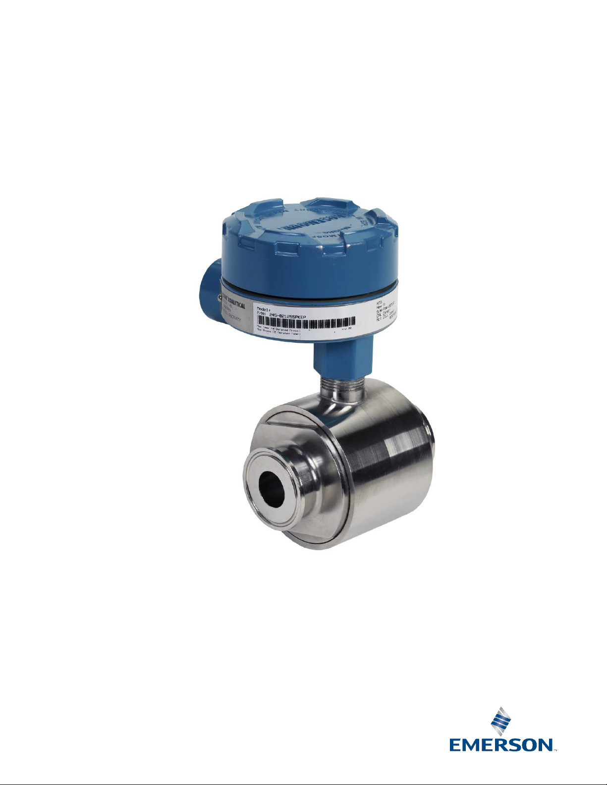
Figure 1-1 Sanitary Flow-Through Toroidal Conductivity Sensor
1.3 Ordering Information
The 245 Sanitary Flow-Through Sensor is configurable to meet the needs of many
applications and installations. A NEMA 7D junction box is also included. Compatible
instruments include Rosemount 1056, 56, 5081T, and 1066-T.
The extension cable required for wiring from the junction box to the instrument is ordered
separately. The customer supplies the mating flanges, clamps, gaskets, and Pt 1000 RTD.
Model 245 Sanitary Flow-Through Toroidal Conductivity Sensor
CODE LINE SIZE (Required Selection)
01 ½”
02 1”
03 1–½”
04 2”
CODE PROCESS CONNECTION (Required Selection)
12 Tri Clamp
CODE CONTACT RING MATERIAL (Required Selection)
SS 316L Stainless Steel
CODE LINER MATERIAL (Required Selection)
PK unfilled PEEK
CODE PROCESS O-RING MATERIAL (Required Selection)
EP EP O-rings
245 -01 -12 -SS -PK -EP EXAMPLE
Accessories
Part # Description
23909-00 Extension cable, prepped, for connection to instruments 1056, 56, 5081, 1066-T (Specify length)
24086-00 RTD Mounting Accessory Kit, consisting of ¾” NPT tee, nipple, and cable connectors
2 245 Sensor
Page 9

Instruction Manual 245 Sensor
Note
1. The sensor should be installed into a straight section of piping at least 4 pipe diameters
Note
LIQ-MAN-245 June 2017
1.4 Installation
Before starting installation, determine whether the analyzer/transmitter will be calibrated at
the bench or on-line. If bench calibration is to be performed, wiring instructions can be found
at the end of this section and calibration procedures can be found in Section 1.5.
Installation of the 245 Flow Through Sensor is similar to installation of a section of pipe.
Consequently, be prepared to use tools, supplies, equipment, and techniques similar to
those used to install process pipes. Use common piping practices to minimize torque and
bending loads on process connections. Observe all applicable safety standards. Dimensional
information is shown in Figure 1-2 below.
in length on either side of the sensor to optimize sensor performance.
2. The sensor should be installed at an orientation that will keep the sensor filled with
process solution at all times during which measurements are being made. Avoid
downward flowing solutions as such a configuration might leave the sensor partially
empty.
Installing the Sensor in the Process Line
1. Install Tri-Clamp flanges onto pipes in accordance with applicable instructions, standards,
and local regulations.
2. Position the sensor between the Tri-Clamp flanges with the flange gaskets inserted
between each set of flanges. Ensure that the locations of the junction box connection and
the RTD are suitable for ease of the remainder of installation, wiring, and use.
Installing the Pt100 RTD
1. Use of the optional Pt100 RTD is recommended. Use of a customer-supplied Pt100 or
Pt1000 TC mounted in a separate thermowell is also acceptable.
2. Thread the RTD wires into junction box. Wire the RTD to the j-box terminals as indicated in
Figure 1-4. Use of optional kit PN 24086-00 is recommended.
Extension Cable Hook-Up
1. Sensor cable should not be run in conduit or open trays with any A.C. power wiring, nor
routed near heavy electrical equipment.
2. For best sensor/instrument loop performance, using the preprepared extension cable (PN
23909-00) is recommended. (Using a different cable can introduce noise into the signal
and/or reduce loop accuracy.)
3. One end of extension cable (PN 23909-00) has 8 wires, and the other end has 11 wires.
Refer to Figure 1-4. The end with only 8 wires goes into the junction box. The end with 11
245 Sensor 3
wires goes to the instrument.
If starting with unprepped cable (PN 9200276), remove only as much insulation as is
necessary. The instrument end needs 11 leads: four leads from the green-white-blackdrain bundle, three from each of the two coaxial cable bundles (the inner conductor, the
insulating braid, and the drain wire), and one from the outermost overall braided-copper
shield. For the junction-box end, only 8 leads are used: the white coaxial conductor, its
braided shield, the green coaxial conductor, its braided shield, its drain wire, and the green,
white, and black conductors from the green-white-black-drain bundle. The remaining
shields and drain wires are not used on the J-box end and should be removed -- they should
NOT be connected or allowed to short to any other conductor or the junction box.
4. Connect the 8 wires of the extension cable to the terminal block inside the sensor’s
junction box as indicated in Figure 1-3 and Figure 1-4.
5. Connect the 11 wires of the instrument-end of the extension cable according to the
applicable diagram from Figures 1-5 through 1-9, the Wiring Instruction Sheet, or the
instrument’s instructions.
Page 10

245 Sensor Instruction Manual
June 2017 LIQ-MAN-245
Figure 1-2 245 Junction Box with RTD Diagram (use of optional kit PN 24086-00 is
recommended)
1.5 Calibration
Before starting the calibration, enter the nominal cell constant into the analyzer. See Table
1-1. The accuracy of the nominal cell constant is probably no better than 10%. For greater
accuracy, calibrate the sensor.
Table 1-1 Nominal Cell Constants for 245 Sensors
Sensor Size Nominal Cell Constant
½” 8
1” 2
1.5” 1.6
2” 1.3
1.5.1 Calibration against a standard solution
1. Obtain a suitable conductivity standard. If the sensor is being used to measure a broad
range of conductivity, choose a standard in the midpoint of the operating range.
Otherwise, choose a standard near the expected process conductivity.
2. Attach a blank flange to one end of the sensor. Stand the sensor on the sealed end.
3. Decide whether temperature correction is needed.
a. If the conductivity of the standard as a function of temperature is known, configure
the analyzer to measure raw conductivity (no temperature correction). Also, obtain
a calibrated thermometer. Place the thermometer in a beaker of water next to the
sensor. DO NOT PUT THE THERMOMETER IN THE SENSOR.
b. If the conductivity of the standard is known only at 25 ºC, leave the analyzer slope
temperature correction on and set the temperature coefficient to the appropriate
4 245 Sensor
value. If the temperature coefficient is not given, consult the manufacturer of the
standard. Also, obtain a calibrated Pt 100 RTD and connect it to the analyzer. See
Wiring Diagrams. Place the RTD in a beaker of water next to the sensor. DO NOT PUT
THE RTD IN THE SENSOR
4. Fill the sensor with standard. Be sure no air bubbles are sticking to the liner and the sensor
is completely filled.
5. Wait for the standard and the water in the beaker containing the thermometer or RTD to
come to thermal equilibrium.
6. Refer to the analyzer instruction manual and adjust the analyzer display to match the
conductivity of the standard at either the temperature of the standard (step 3a) or at 25 ºC
(step 3b).
Page 11

NOTE
Instruction Manual 245 Sensor
LIQ-MAN-245 June 2017
1.5.2 In-line calibration against a laboratory measurement
1. Install the sensor in the process piping.
2. Obtain and calibrate a laboratory conductivity meter and sensor capable of measuring the
conductivity of the process liquid.
3. Collect a sample of the process liquid and measure the conductivity using the laboratory
instrument. The temperature of the sample is likely to change during handling. For this
reason, use temperature compensation in both the process and laboratory analyzer. Be
sure the temperature correction algorithms are identical.
4. Refer to the analyzer instruction manual and adjust the analyzer display to match the
conductivity measured in the laboratory.
1.6 Calibration Verification
Calibration verification is a way of monitoring changes that might occur in the external
toroids during service. It does not detect changes in the contact rings. It is not a calibration.
1. Empty and dry the sensor.
2. Attach a resistance decade box to the two yellow wires. See Figure 2-1.
3. Configure the analyzer to measure raw conductivity (no temperature compensation).
4. Adjust the resistance until the analyzer display reads the same number it did during
calibration. Record the resistance value, the displayed value, and the temperature.
Calibration verification can be used to check the toroids while the sensor is in the process line.
1. Drain the process line.
2. Connect a resistance decade box to the yellow wires.
3. Configure the analyzer to measure raw conductivity.
4. Set the decade box to the value noted in step 4 above. The analyzer reading should match
the original reading to within ±20%.
1.7 Wiring
For additional wiring information on this product, including sensor combinations not
shown here, please refer to the Liquid Transmitter Wiring Diagrams
Figure1-3 Sensor to Junction Box Wiring
.
245 Sensor 5
Page 12

245 Sensor Instruction Manual
June 2017 LIQ-MAN-245
Figure 1-4 Extension Cable
Figure1-5 Wiring extension cable to 54ec
Figure1-6 Wiring extension cable for 1056 and 56
Figure1-7 Wiring extension cable to Xmt-T (Panel Mount)
6 245 Sensor
Page 13

CLEAR SHIELD
CONNECTED. I
IN HIGH TEMPE
Instruction Manual 245 Sensor
CLEAR
GREEN
WHITE
BLACK
BLACK
GREEN
CLEAR
BLACK
WHITE
CLEAR
LIQ-MAN-245 June 2017
Figure1-8 Wiring extension cable to Xmt-T (Pipe/Wall Mount)
Figure1-9 Wiring extension cable to 1066-T Figure 1-10 Wiring extension Cable to 5081T
RTN
SENSE
RTD IN
SHLD
TB2
TB1
RCV B
RCV A
RSHLD
DRV B
DRV A
DSHLD
CLEAR
(OPTION-03) ON
228-56
1.8 Maintenance
The only routine maintenance required during the operational life of the sensor is to ensure
that there are no deposits plugging the sensor or coating the inside of the contact rings.
Some customers find it advantageous to periodically replace process (Tri-Clamp) gaskets to
ensure adequate process seals. Rebuilding the sensor must be done at the factory.
245 Sensor 7
Page 14

245 Sensor Instruction Manual
June 2017 LIQ-MAN-245
8 245 Sensor
This page left blank intentionally
Page 15

Instruction Manual Troubleshooting
23 / 73.4
108.9
1089
LIQ-MAN-245 June 2017
Section 2: Troubleshooting
2.1 Troubleshooting
To check the toroids, recall the data obtained during the Calibration Verification Process
(see Section 1.6). With the sensor empty of process fluids (preferably also clean and dry),
reapply the resistance to the yellow Cal Loop wires in the junction box. The reading should be
within + 20% of its original value.
To check the RTD, disconnect RTD leads of the interconnecting cable (PN 23909-00) and
measure the resistance across the white and one of the red RTD wire terminals in the junction
box. See Figure 1-4. The resistance value should be close to the applicable value shown in
Table 2-1.
Finally, check the sensor for open connections and short circuits. Be sure to disconnect the
cable (PN 23909-00) before checking. See Table 2-2 and Figure 2-1.
Table 2-1 Resistance Values for Pt 100 and Pt 1000 RTDs
Temperature Resistance (Ohms)
(°C/°F) Pt 100 Pt 1000
18 / 64.4 106.9 1069
19 / 66.2 107.3 1073
20 / 68.0 107.7 1077
21 / 69.8 108.1 1081
22 / 71.6 108.4 1084
24 / 75.2 109.2 1092
25 / 77.0 109.6 1096
26 / 78.8 110.0 1100
27 / 80.6 110.4 1104
Table 2-2. Sensor Wire Resistance Values with Instrument Cable Disconnected
(instrument leads and gray wire connected to terminal block, see Figure 2-1)
Connection (wire or component connections) Resistance
Each twisted pair, WHITE to GRAY 0.4 to 0.9 Ω
YELLOW to YELLOW 0.1 to 0.5 Ω
WHITE to WHITE > 20 MΩ
RED to YELLOW > 20 MΩ
RED to each WHITE > 20 MΩ
YELLOW to each WHITE > 20 MΩ
ALL except RED to housing EARTH screw > 20 MΩ
RED to housing EARTH screw 0.1 to 0.5 Ω
Troubleshooting 9
Page 16

Section Title Instruction Manual
June 2017 LIQ-MAN-245
Figure 2-1 Sensor Circuit for Troubleshooting
10 Troubleshooting
Page 17

Page 18

LIQ-MAN-245
Rev. E
June 2017
www.Emerson.com/RosemountLiquidAnalysis
Youtube.com/user/Rosemount
Twitter.com/Rosemount_News
Emerson Automation Solutions
8200 Market Blvd.
Chanhassen, MN 55317,
USA
Tel +1 800 999 9307
Fax +1 952 949 7001
Liquid.CSC@Emerson.com
Analyticexpert.com
facebook.com/Rosemount
©2017 Emerson Automation Solutions. All rights reserved.
The Emerson logo is a trademark and service mark of Emerson Electric Co. Rosemount is a mark of
one of the Emerson family of companies. All other marks are the property of their respective
owners.
The contents of this publication are presented for information purposes only, and while effort has
been made to ensure their accuracy, they are not to be construed as warranties or guarantees,
express or implied, regarding the products or services described herein or their use or applicability.
All sales are governed by our terms and conditio ns, which are available on request. We reserve the
right to modify or improve the designs or specifications of our products at any time without notice.
 Loading...