

Page 1
TM
Rosemount
242
Toroidal Flow-Through Conductivity Sensor
Instruction Manual
LIQ-MAN-242
Rev. F
June 2017
Page 2
Installations near flammable liquids or in hazardous
not
transmitter, and
sensor combination must be used. The installation
system must comply with the governing approval
hazardous area classification requirements.
any
agency
Proper installation, operation and servicing of this
sensor in a Hazardous Ar ea Installation is entirely
ESSENTIAL INSTRUCTIONS
install,
e within their
and
life; perso nal
Read all instructions prior to installing, operating, and servicing the
7768 and the requested manual will be provided.
If you do not understand any of the instructions, contact your
ow all warnings, cautions, and instructions marked on and
ions of
the appropriate Instruction Manual and per applicable local and
the
ensure proper performance, qualified personnel should install,
people
Replacement of
original components with those constructed from alternative
ELEC
agency approvals that were applicable to the original device.
original
process
an affect the
performance, place the safe operation of your process at
are
is being performed by qualified
READ THIS PAGE BEFORE PROCEEDING!
Rosemount designs, manufactures, and tests its products to meet
many national and international standards. Because these instruments are sophisticated technical products, you must properly
use, and maintain them to ensure they continue to operat
normal specifications. The following instructions must be adhered to
integrated into your safety program when installing, using, and maintaining Rosemount products. Failure to follow the proper/ instructions may
cause any one of the following situations to occur: Loss of
injury; property damage; damage to this instrument; and warranty
invalidation.
•
product. If this Instruction Manual is not the correct manual, telephone 1-800-654Save this Instruction Manual for future reference.
•
Rosemount representative for clarification.
• Foll
supplied with the product.
• Inform and educate your personnel in the proper installation, operation, and maintenance of the product.
• Install your equipment as specified in the Installation Instruct
national codes, for example, ANSI B16.5. Connect all products to
proper electrical and pressure sources.
• To
operate, and maintain the product.
• When repla cement parts are required, ensure that qualified
use replacement parts specified by Rosemount.
materials will void any CSA, FM, and BASEEFA/CENFurthermore, replacement of original components with those con-
structed from alternative materials might change the pressure, temperature, and/or performance specifications from those of the
configuration. Ensure replacement parts are compatible with
requirements. Unauthorized parts and procedures c
product’s
risk, and may result in fire, electrical hazards, or improper operation.
• Ensure that all equipment doors are closed and protective covers
in place, except when maintenance
persons, to prevent electrical shock and personal injury.
DANGER
HAZARDOUS AREA INSTALLATION
area locations mus t be caref ully evaluated by qualified on site safety personnel. This sensor is
Intrinsically Safe or Explosion Proof.
To secure and maintain an intrinsically safe installation, the certified safety barrier,
agency (FM, CSA, BASEEFA/CENELEC, or ATEX)
Consult your anal yzer/trans mitter instruction m anu-
al for details.
Replacement of original components with those con-
structed from alternative materials will void
CSA, FM, and BASEEFA/CENELEC
approvals that were applicable to the original device.
the responsibility of the user.
APPLICATION COMPATIBILITY
The wetted sensor materials may not be compatible
with process com pos iti on a nd oper a tin g co nditions.
Replacement of original components with those constructed from alternative materials might change the
pressure, temperatur e, and/or perform ance spec ifications from thos e of the origin al sensor configur ation. Application compat ibi li t y is entirely the responsibility of the user.
CAUTION
SENSOR/PROCESS
Page 3

MODEL 242
TABLE OF CONTENTS
Rosemount 242
TOROIDAL CONDUCTIVITY SENSOR
TABLE OF CONTENTS
Section Title Page
1.0 MODEL 242 SENSOR ............................................................................................. 1
1.1 Features and Applications........................................................................................ 1
1.2 Specifications ........................................................................................................... 2
1.3 Ordering Information ................................................................................................ 5
1.4 Installation ................................................................................................................ 7
1.5 Calibration ................................................................................................................ 10
1.6 Maintenance ............................................................................................................ 13
2.0 Troubleshooting ..................................................................................................... 14
3.0 Replacement Parts................................................................................................. 16
3.1 General .................................................................................................................... 16
3.2 Remove the Sensor From the Process .................................................................... 16
3.3 Disassemble the Sensor .......................................................................................... 16
3.4 Re-assemble the Sensor ......................................................................................... 19
3.5 Re-install the Sensor into the Process ..................................................................... 19
4.0 Return of Materials ................................................................................................ 20
LIST OF TABLES
Table No. Title Page
1-1 Nominal Cell Constants for 242 Sensors................................................................. 10
2-1 Resistance vs. Temperature for RTD (Resistance Temperature Detector) ............. 14
2-2 Sensor Resistance Check........................................................................................ 14
3-1 Replacement Parts and Accessories ....................................................................... 17
3-2 Sensor Bolt Removal & Installation Guide............................................................... 18
i
Page 4

MODEL 242
Rev. Level
Date
Notes
E
03/12
Update addresses pages 22 and 24
TABLE OF CONTENTS
MODEL 242
TOROIDAL CONDUCTIVITY SENSOR
LIST OF FIGURES
Figure No. Title Page
1-1 Pressure-Temperature Specs for 1”, 1.5”, & 2” Sensors: Models 242-02/03/04 .... 3
1-2 Pressure-Temperature Specs for 3” & 4” Sensors: Models 242-06/08 ................... 3
1-3 Pressure-Temperature Specs for 1” & 2” Sensors: Alumina Liner .......................... 4
1-4 Pressure-Temperature Specs for 3” & 4” Sensors: Alumina Liner .......................... 4
1-5 Dimensional Drawing ............................................................................................... 7
1-6 Installation and Torque Guidelines........................................................................... 8
1-7 Sensor to Junction Box Wiring ................................................................................ 9
1-8 Sensor/Junction Box/RTD Assembly ....................................................................... 9
1-9 Extension Cable ...................................................................................................... 10
1-10 Extension Cable to Instrument Model 54eC Wiring................................................ 11
1-11 Extension Cable to Instrument Model 1055 Wiring ................................................. 11
1-12 Extension Cable to Instrument Models 3081T & 4081T Wiring............................... 12
1-13 Extension Cable to Instrument Model 81T Wiring ................................................... 12
1-14 Extension Cable to Instrument Model Xmt Pipe/Wall Mount Enclosure.................. 12
1-15 Extension Cable to Instrument Model Xmt Panel Mount Enclosure........................ 13
2-1 Sensor Circuit for Troubleshooting .......................................................................... 15
3-1 Model 242 Sensor - Exploded View ........................................................................ 18
3-2 Flange Assembly...................................................................................................... 19
About This Document
This manual contains ins tructions for installation and operation of the Model 242 Flow-Through
Toroidal Conductivit y Sensor. The following list provides notes concerning all revisions of this document.
A 11/02 This is the initial release of the product manual. The manual has been
reformatted to reflect the Emerson documentation style and updated to reflect
any changes in the product offering.
B 8/03 Corrected wiring references in text and drawings. Added information regarding
ATEX approvals with Model 5081T.
C 5/04 Added information regarding the alumina liner, and updated wiring diagrams.
D
ii
Page 5
MODEL 242
SECTION 1.0 242 SENSOR
•
FLOW THROUGH DESIGN is ideal for use with viscous,
abrasive, or fibrous process liquids.
SECTION 1.0
242 SENSOR
• OVER 250 CONFIGURATIONS to meet customers' needs.
• REPLACEABLE LINER in glass-filled PEEK, TEFLON, or
ALUMINA reduces long-term operating costs.
•
DIN and ANSI FLANGES compatible with all piping installations.
•
LINE SIZES of 1 through 4 inches (DN 25, 40, 50, 80 and
100).
• IN-LINE CALIBRATION saves money by reducing labor
and down-time.
• TEMPERATURE SENSOR and JUNCTI ON-BOX included.
1.1 FEATURES AND APPLICATIONS
Rosemount Toroidal Conductivity Sensors are ideal
for use in processes where contacting sen- sors -those with electrodes exposed to the measured
solution -- would corrode or become fouled.
The 242 Flow Through Toroidal conductivity sensor
consists of two toroids surrounding a pipe through
which the process liquid flows. One toroid acts as a
transmitter and the other as a rec eiver. Energi zing the
transmitter toroid induces an electric current in the
process solution which induces an electric current in
the receiver toroid. T he s tr engt h of th e i nduc e d c urr en t
is directly proport ional to the conductivity of the solution.
The 242 sensor is availab le in over two hundred fifty
configurations to meet the needs of m any applications
and installations. Line sizes of 1, 1.5, 2, 3, and 4 inch-
es (25, 40, 50, 80, and 100 mm) are available with
both ANSI and DIN compatible flanges. A variety of
liner materials and O-rings are available to ensure
compatibility with most process liquids.
The 242 sensor is easy to install. It fits in the process
piping between mounting flanges. Spec ial grounding
rings are not needed because the sensor has contact rings built into it. Rec es sed bo lts hold the s ensor
together to ensure all internal parts stay in perfect
alignment. A junction box and a Pt 100 RTD are
included. The RTD slips ea sil y into on e of the sens or
contact rings. T here is no need to insta ll a separate
thermowell, and temperature measurements are
made at the sam e po int as the c o nductivity measurements.
The sensor is not sensit ive to flow rate or direction.
It does not obstruct t he process flow. The sensor is
rugged and constructed from chemically resistant
materials. All these features make the sensor ideal
for applications in mining and metals processing,
pulp and paper processing, and the chemical processing industry.
The 242 Flow Throug h Conductivity Sensor is com patible with instrument instumentsL 54eC, 1055,
3081T, 4081T, 5081-T, and Xmt-T.
1
Page 6
MODEL 242
MODEL 242 SENSOR
Installation Type
Flow Through
Conductivity Range
Process Connections
150# ANSI, 300# ANSI, PN16 DIN 2501 compatible flanges
Maximum Temperature
Maximum Pressure
Wetted Materials:
Shipping Weight
SECTION 1.0
1.2 SPECIFICATIONS
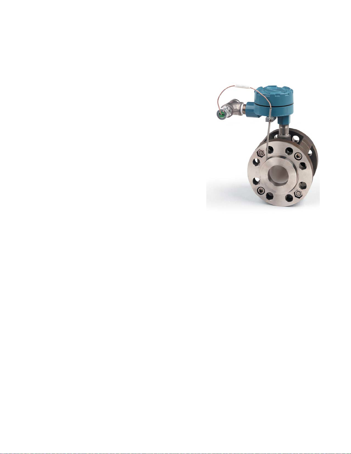
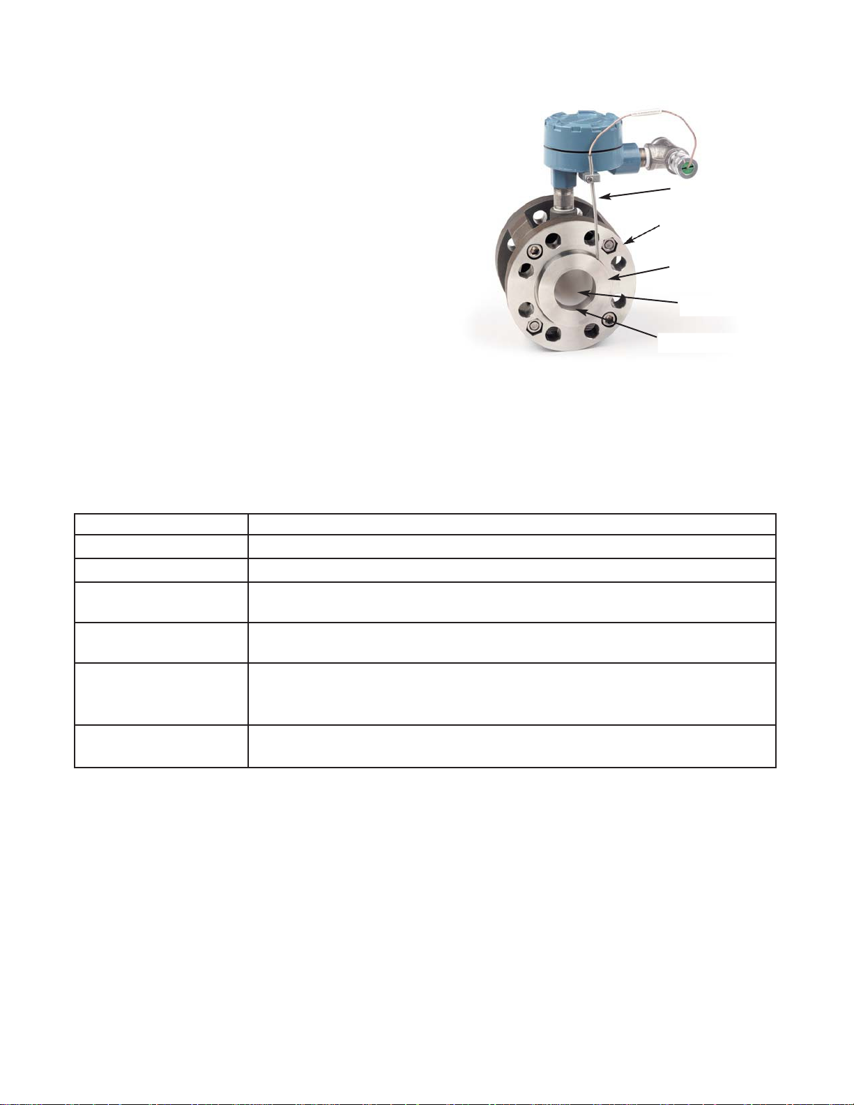
The Model 242 Flow Through Sensor comprises a toroid
housing constructed from 316 stainless steel and polyethyleneterephthalate, process connection flanges of 316
stainless steel, two metal c ontact rings (available in choice
of three materials), an insulating liner (choice of three
materials), O-rings (choice of three materials), a Pt 100
RTD, and a sensor-mounted junction box. Only the liner,
contact rings, and O-rings are wetted b y the process. The
Pt 100 RTD is designed for insertion into one pre-drilled
contact ring. The NEMA 7D junction box is constructed of
heavy duty epoxy-painted cast aluminum . The conductivity
range is user-selectable with the tappe d toroid windings. Inline calibration can be perform ed with resistors connect- ed
to an integral wire around the toroids that is terminated in
the junction box.
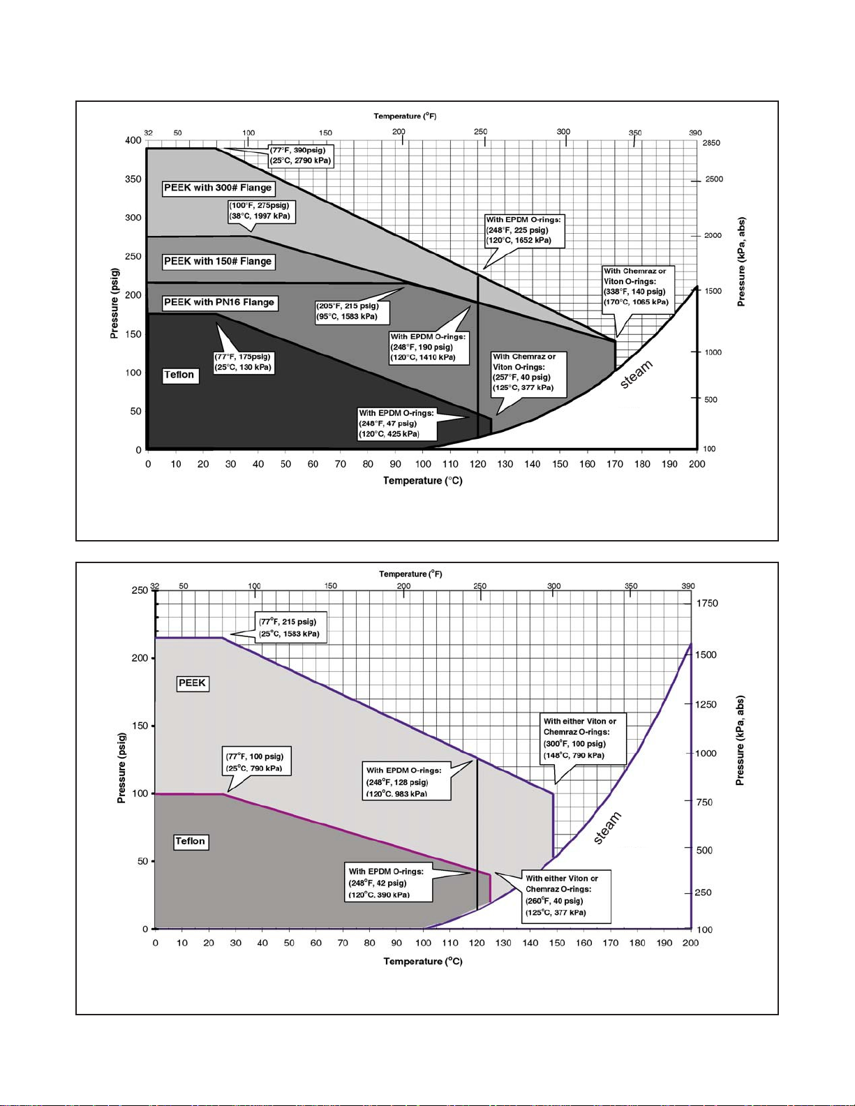
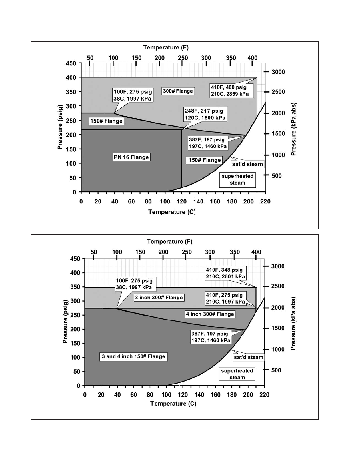
Liners are available in T eflon, glass-filled Polyetherether ketone (PEEK), and alumina. These m aterials provide
excellent chem ical resistance. P EEK is recom mended for high pressure or high tem perature appl ications. Tef lon
is recommended when the process solution contains hydrofluoric acid or other strong oxidizing agents. Alumina is
recommended if the process solution is abrasive, such as in alumina/caustic ratio applications.
Pt 100 RTD
Flange
Contact Ring
Liner
O-ring (not visible)
100 μS/cm to 2 S/cm
Depends on configuration. For plastic-lined sensors, see charts on facing page.
For alumina-lined sensors, see charts on page 4.
Depends on configuration. For plastic-lined sensors, see charts on facing page.
For alumina-lined sensors, see charts on page 4.
Liner
Contact Rings
O-rings
®
Teflon
(PTFE), glass-filled PEEK, or alumina
316 SST, Carpenter 20Cb-3
EPDM, Viton
1” to 2”: 22 lbs. (10kg)
3” to 4”: 86 lbs. (39 kg)
Teflon is a registered trademark of E.I. du Pont de Nemours & Co.
Viton is a registered trademark of Du Pont Dow Elastomers.
Carpenter 20Cb-3 is a registered trademark of Carpenter Technologies.
Hastelloy is a registered trademark of Haynes International.
Chemraz is a registered trademark of Greene, Tweed, & Co.
2
®
SST, or Hastelloy® C-276
®
(FKM), or Chemraz® (FFKM)
Page 7
MODEL 242
MODEL 242 SENSOR
FIGURE 1-1. Pressure - Temperature Specifications for 1”, 1.5”, and 2” (25, 40, and 50 mm) Sensors:
SECTION 1.0
Models 242-02, 242-03, and 242-04
FIGURE 1-2. Pressure - Temperature Specifications for 3” and 4” (80 and 100 mm) Sensors:
Models 242-06 and 242-08
3
Page 8
MODEL 242
MODEL 242 SENSOR
FIGURE 1-4. Pressure - Temperature Specifications for 3” and 4” Sensors: Alumina Liner
SECTION 1.0
4
FIGURE 1-3. Pressure - Temperature Specifications for 1” and 2” Sensors: Alumina Liner
Page 9

MODEL 242
MODEL 242 SENSOR
242
FLOW THROUGH TOROIDAL CONDUCTIVITY SENSOR
CODE
LINE SIZE (Required Selection)
02
1”
DN 25 03
1-1/2”
DN 40 04
2”
DN 50 06
3”
DN 80
(no ATEX approval with 5081T)
08
4”
DN 100
(no ATEX approval with 5081T)
CODE
PROCESS CONNECTION (Required Selection)
10
150# ANSI Flange (Line sizes 1", 1-1/2", 2”, 3”, 4”)
11
300# ANSI Flange (Line sizes 1", 1-1/2", 2”, 3”, 4”)
14
PN 16 Metric Flange (Line sizes DN 25, 40, 50, 80, 100)
CODE
CONTACT RING MATERIAL (Required Selection)
SS
316 Stainless Steel
H4
Hastelloy C-276 (Line Sizes 1", 1-1/2", 2”, 25mm, 40mm, 50mm)
H8
Hastelloy C-276 (Line Sizes 3", 4", 80mm, 100mm)
C4
Carpenter 20-Cb3 (Line Sizes 1", 1-1/2", 2”, 25mm, 40mm, 50mm)
CODE
LINER MATERIAL (Required Selection)
TE
PTFE (Teflon®)
G4
PEEK, 30% Glass-Filled (Line Sizes 1", 1-1/2", 2”, 25mm, 40mm, 50mm)
G8
PEEK, 30% Glass-Filled (Line Sizes 3", 4", 80mm, 100mm)
A4
Alumina (Line sizes 1”, 2”, 25 mm, 50 mm); available only with option F4
A8
Alumina (Line sizes 3”, 4”, 80 mm, 100 mm); available only with option F8
CODE
PROCESS O-RING MATERIAL (Required Selection)
EP
Ethylene Propylene Rubber
VT
Fluorocarbon Rubber (Viton
®
)
F4
High Temp. Perfluoroelastomer (Chemraz
)
(Line Sizes 1", 1-1/2", 2”, 25mm, 40mm, 50mm)
1.3
ORDERING INFORMATION
SECTION 1.0
The 242 Flow-T hrough Sensor is configurable to meet the needs of many applications an d installations (both
ANSI and DIN). After specifying line size and flange type, the customer selects the wetted materials most compatible with the process stream. A NEMA 7D junction box and Pt 100 RTD are also included. Compatible instruments
include Rosemount Models 54eC, 1055, 3081T, 4081T, 5081-T, and Xmt-T.
The extension cable requ ired for wiring from the junction box to th e instrument m ust be ordered separatel y. The
customer supplies the gaskets, mating flanges, and flange bolts.
C8 Carpenter 20-Cb3 (Line Sizes 3", 4", 80mm, 100mm)
F8
242 -0611SSG8VT EXAMPLE
High Temp. Perfluoroelastomer (Chemraz
®
®
) (Line Sizes 3", 4",
80mm, 100mm
)
5
Page 10

MODEL 242
MODEL 242 SENSOR
PART NUMBER
DESCRIPTION
4081T, 5081-T, and Xmt-T (Specify length)
KIT PN
DESCRIPTION
FOR SENSOR MODELS
24005-00
Kit, Liner, 1” DN 25, Teflon PTFE
242-02[ ]TE[ ]
24005-01
Kit, Liner, 1” DN 25, glass-filled PEEK
242-02[ ]G4[ ]
24005-02
Kit, Liner, 1” DN 25, Alumina
242-02[ ]A4[ ]
24006-00
Kit, Liner, 1-1/2” DN 40, Teflon PTFE
242-03[ ]TE[ ]
24006-01
Kit, Liner, 1-1/2” DN 40, glass-filled PEEK
242-03[ ]G4[ ]
24007-00
Kit, Liner, 2” DN 50, Teflon PTFE
242-04[ ]TE[ ]
24007-01
Kit, Liner, 2” DN 50, glass-filled PEEK
242-04[ ]G4[ ]
24007-02
Kit, Liner, 2” DN 50, Alumina
242-04[ ]A4[ ]
24008-00
Kit, Liner, 3” DN 80, Teflon PTFE
242-06[ ]TE[ ]
24008-01
Kit, Liner, 3” DN 80, glass-filled PEEK
242-06[ ]G8[ ]
24008-02
Kit, Liner, 3” DN 80, Alumina
242-06[ ]A8[ ]
24009-00
Kit, Liner, 4” DN 100, Teflon PTFE
242-08[ ]TE[ ]
24009-01
Kit, Liner, 4” DN 100, glass-filled PEEK
242-08[ ]G8[ ]
24009-02
Kit, Liner, 4” DN 100, Alumina
242-08[ ]A8[ ]
KIT PN
DESCRIPTION
FOR SENSOR MODELS
24010-00
Kit, O-Ring, 1” DN 25, EPDM
242-02[ ]EP[ ]
24010-01
Kit, O-Ring, 1” DN 25, Viton
242-02[ ]VT[ ]
24010-02
Kit, O-Ring, 1” DN 25, Chemraz
242-02[ ]F4[ ]
24010-03
Kit, O-Ring, 1” DN 25, Chemraz for use with Alumina liner
242-02[ ]A4-F4
24011-00
Kit, O-Ring, 1-1/2” DN 40, EPDM
242-03[ ]EP[ ]
24011-01
Kit, O-Ring, 1-1/2” DN 40, Viton
242-03[ ]VT[ ]
24011-02
Kit, O-Ring, 1-1/2” DN 40, Chemraz
242-03[ ]F4[ ]
24012-00
Kit, O-Ring, 2” DN 50, EPDM
242-04[ ]EP[ ]
24012-01
Kit, O-Ring, 2” DN 50, Viton
242-04[ ]VT[ ]
24012-02
Kit, O-Ring, 2” DN 50, Chemraz
242-04[ ]F4[ ]
24012-03
Kit, O-Ring, 2” DN 50, Chemraz for use with Alumina liner
242-04[ ]A4-F4
24013-00
Kit, O-Ring, 3” DN 80, EPDM
242-06[ ]EP[ ]
24013-01
Kit, O-Ring, 3” DN 80, Viton
242-06[ ]VT[ ]
24013-02
Kit, O-Ring, 3” DN 80, Chemraz
242-06[ ]F8[ ]
24013-03
Kit, O-Ring, 3” DN 80, Chemraz for use with Alumina liner
242-06[ ]A8-F8
24014-00
Kit, O-Ring, 4” DN 100, EPDM
242-08[ ]EP[ ]
24014-01
Kit, O-Ring, 4” DN 100, Viton
242-08[ ]VT[ ]
24014-02
Kit, O-Ring, 4” DN 100, Chemraz
242-08[ ]F8[ ]
ACCESSORIES
23909-00 Extension cable, Pre-prepped, for connection to Instrument Models 54eC, 1055, 3081T,
SECTION 1.0
24014-03 Kit, O-Ring, 4” DN 100, Chemraz for use with Alumina liner 242-08[ ]A8-F8
6
Page 11
MODEL 242
handled. Do NOT place any object through the liner for
Support structures sho uld be installed as appropriate on
ly support the weight of the sensor during insta llation and
1.4 INSTALLATION
In the instructions below, the Junction Box is installed
after the sensor is bo lted into the process line. If appr opriate for the site and final mounting configuration, the
Junction Box can be installed prior to bolting the sensor
into the process line.
CAUTION
The liner of the Model 242 sensor can be damaged if misthe purpose of lifting the Model 242 sensor.
CAUTION
or around process p ipes and s ensor locat ion to suf ficientminimize strain on adjacent process pipes during the
operational life of the sensor.
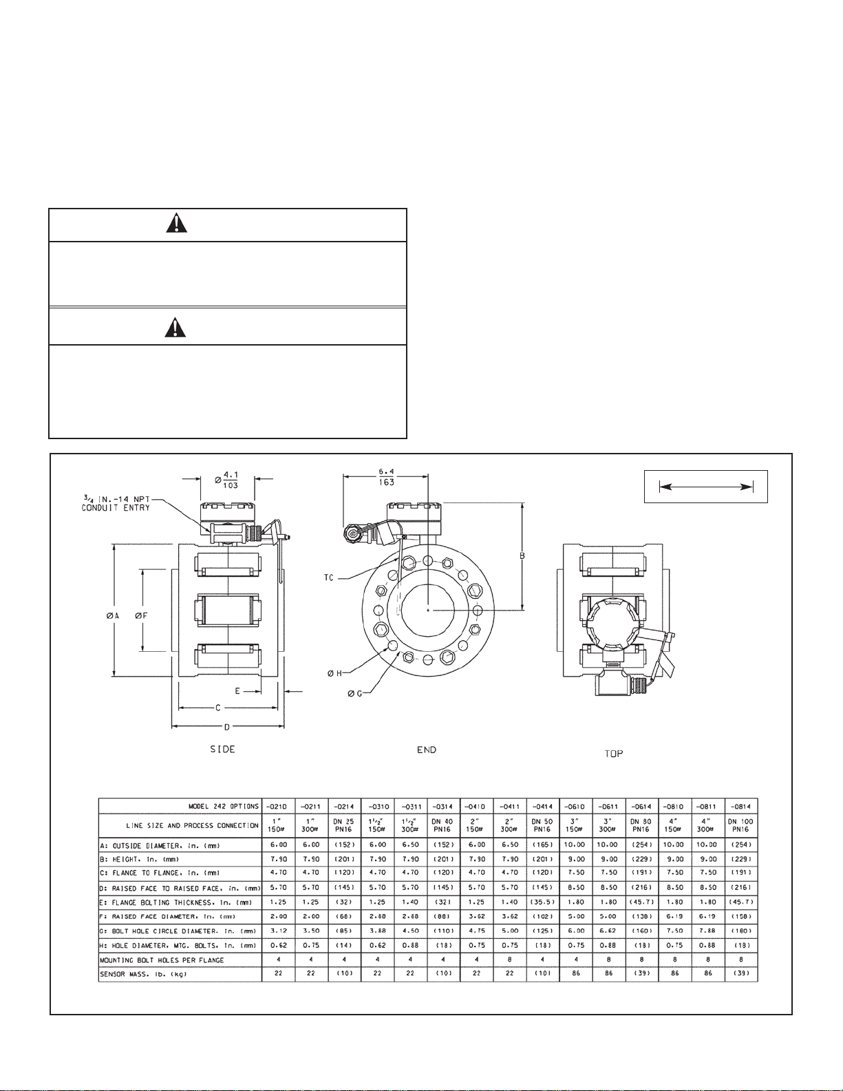
FIGURE 1-5. DIMENSIONAL DRAWING
MODEL 242 SENSOR
SECTION 1.0
Installation of the Mod el 24 2 F lo w Through Sensor is s imilar to installation of a section of pipe. Consequently, be
prepared to use tools, supplies, equipment, and techniques sim ilar to those used to instal l process pipes. Use
common piping practices t o minimize torque and bendin g
loads on process connections. Observe all applicable
safety standards. Dimensional information is shown in
Figure 1-5 below. Refer to Figures 1-6 t o 1-8 for as sembly
and installation diagrams.
NOTES
1. Allow at least f our pipe diameters of straight pip e run
on either side of the sensor.
2. Install the sensor so that it is filled with proces s liquid
at all times when measurements are being made.
Avoid downward flow as such a configuration might
leave the sensor partially empty.
3. Use a sling and hoist to lift and position the sensor.
INCH
MILLIMETER
7
Page 12
MODEL 242
MODEL 242 SENSOR
SECTION 1.0
INSTALLING THE SENSOR IN THE PROCESS LINE
1. Install process flanges in accordance with applicable instructions, standards, and local regulations.
2. Position the sensor bet ween the process mating flanges with flange gaskets inserted betwee n each set of
flanges. Ensure that the lo cations of the juncti on box connection a nd the RTD hole in the cont act ring are in
the correct position for easy wiring and use.
3. Align the bolt holes in the sensor and process flanges.
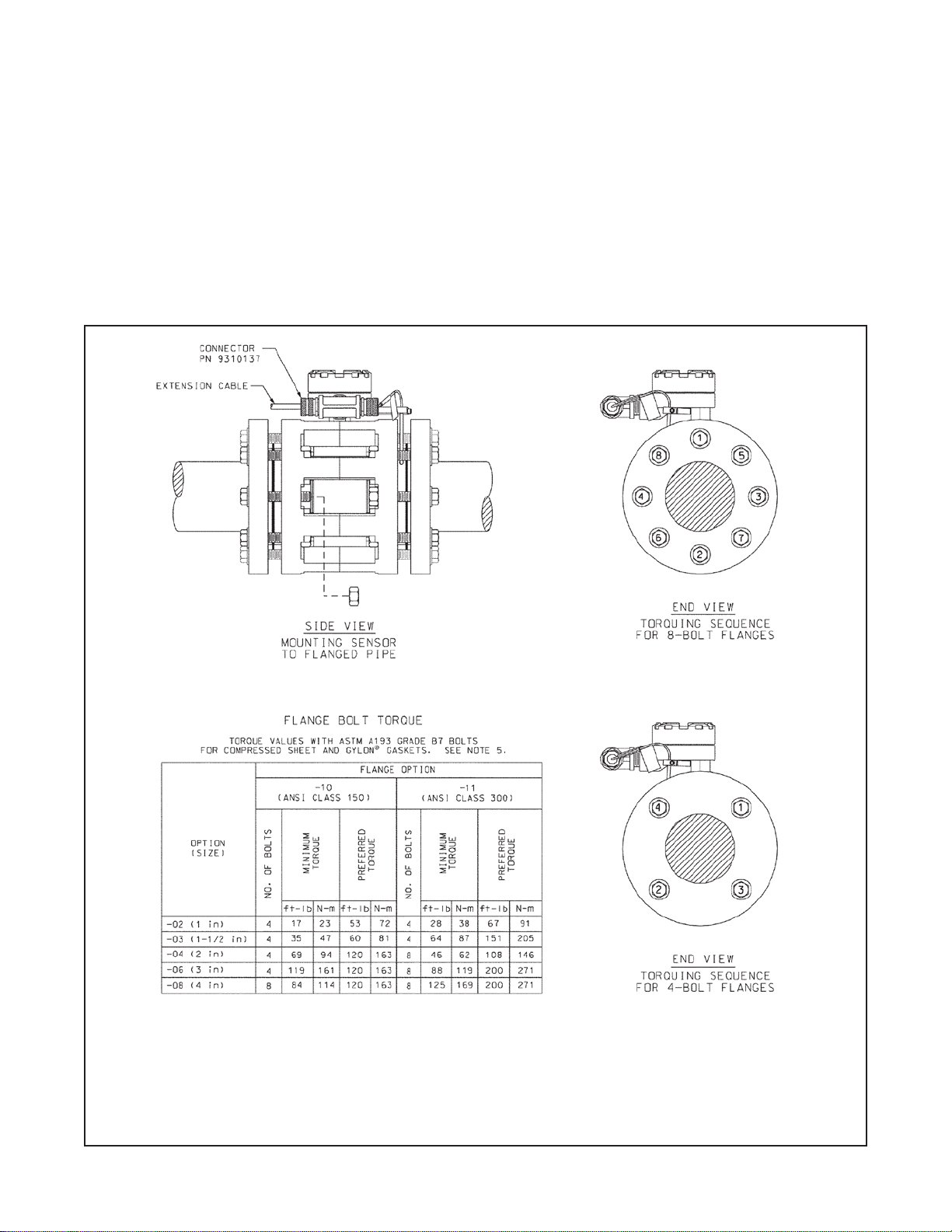
4. Lubricate the bolt threa ds. Using a torque wrench, bol t the sensor into place. Tight en the bolts in 1/3 increments of the final desire d torque. Follow the bolt-tightening sequence and torque suggestions provided in
Figure 1-6.
5. Re-torque the bolts 12 to 2 4 hours after installation . Mak e a final check of torque values b y moving consec utively from bolt to bolt.
Torque values in the table above are from Garlock Sealing Technologies. Other values might apply
when using different bolt and gasket materials.
®
Gylon
is a registered Trademark of Garlock Sealing Technologies.
FIGURE 1-6. Installation and Torque Guidelines
8
Page 13

MODEL 242
MODEL 242 SENSOR
ATTACHING THE JUNCTION BOX
1. Pull the sensor wires up into the junction box.
2. Screw the junction box onto the threaded male connection on
the sensor. Use of pipe sealing tape or other compound is at the
discretion of the customer.
3. Connect the sensor wires to the junction box terminal as indicated in Figure 1-7.
INSTALLING THE Pt100 RTD
1. Use of the included Pt100 RTD is recommended. Use of a customer-supplied Pt100 or Pt1000 TC mounted in a separate thermowell is also acceptable. The accuracy specifications provided
by Rosemount apply only to situations wherein the Pt100 RTD
supplied with the sensor is used.
2. Refer to Figure 1-8. Screw the threaded nipple onto the conduit
connector of the junction box. Screw the tee onto the nipple, and
screw the RTD cable connector onto the tee.
3. Attach the bracket to the shaft of the RTD using the #10 washer
and small screw enclosed in the RTD kit. The purpose of the
bracket is to retain the RTD in the contact ring after installation.
4. Slide the Pt100 RTD into the pre-drilled hole in the contact ring.
Rotate the bracket to a position beneath the junction box, and
tighten the set screw.
5. Thread the RTD wires through cable connector, tee, nipple, and into junction box. Wire the RTD to the junction box terminals as
indicated in Figure 1-7. Install the white jumper wire between terminal s 1 and 2.
*For optimal performance below 10,000 µS/cm, connect
green wire from extension cable to terminal indicated by *
FIGURE 1-7. Sensor to Junction Box Wiring
SECTION 1.0
Items 1-9 are included with the Model 242
sensor. Items 3-9, the white jumper wire,
and Teflon tape are included in the TC kit.
Items 10 and 11 are sold separately as
accessories.
FIGURE 1-8. Sensor/J-bo x/RTD Assembly
9
Page 14

MODEL 242
MODEL 242 SENSOR
Sensor Size
Cell Constant (/cm)*
Black Orange
* The table gives the cell constant when the green receive
Figures 1-7 and 2-1.
1”, DN 25
20
2.0
1.5”, DN 40
9.0
0.90
2”, DN 50
5.0
0.50
3”, DN 80
4.0
0.40
4”, DN 100
2.3
0.23
SECTION 1.0
EXTENSION CABLE HOOK UP
1. Do not run sensor cab le in conduit or open trays
with A.C. power wiri ng. Do not rout e sensor cable
near heavy electrical equipment.
2. For best sensor/instrument loop performance, use
factory-terminated ex te nsio n c abl e (PN 23909-00).
(Using a different cable can introduce noise into
the signal and/or reduce loop accuracy.)
3. One end of extension cabl e (PN 23909-00) has 8
wires, and the other end has 11 wires. Refer to
Figure 1-9. The end with 8 wires goes into the junction box. The end with 11 wires goes to the instrument. The extension cab le enters the j unction box
through the open sid e of the fem ale threaded tee.
Use of conduit, th e optional cable connector (PN
9310137), or other strain relief device to protect the
cable is at the discretion of the customer and
should comply with applicable agency guidelines.
NOTE
If starting with unprepped cable (PN 9200276), remove
only as much insulation as is necessary. The instrument end needs 11 leads: four leads from the greenwhite-black-drain bundle, three from each of the two
coaxial cable bundles (the inner conductor, the insulating braid, and the drain wir e), and one f rom the out ermost overall braided-copper shield. For the junction
box end, only 8 leads are used: t he wh ite coaxi al conductor, its braided shield, the green coaxial cond uctor,
its braided shield, its dr ain wire, and the gre en, white,
and black conductor s f r om the green-white-black-drain
bundle. The rem aining shields a nd drain wires ar e not
used on the junction box end and should be removed -
- they should NOT be connected.
4. Connect the 8 wires of the extension cable t o the
terminal block inside the sensor junction box as
indicated in Figur e 1-7. Note: If all process m easurements will be less than 10,000 µS/cm, connec t
the green wire from the black-green-clear wire bundle of the extension ca ble t o the terminal receiving
the orange sensor wire. See Figure 1-7.
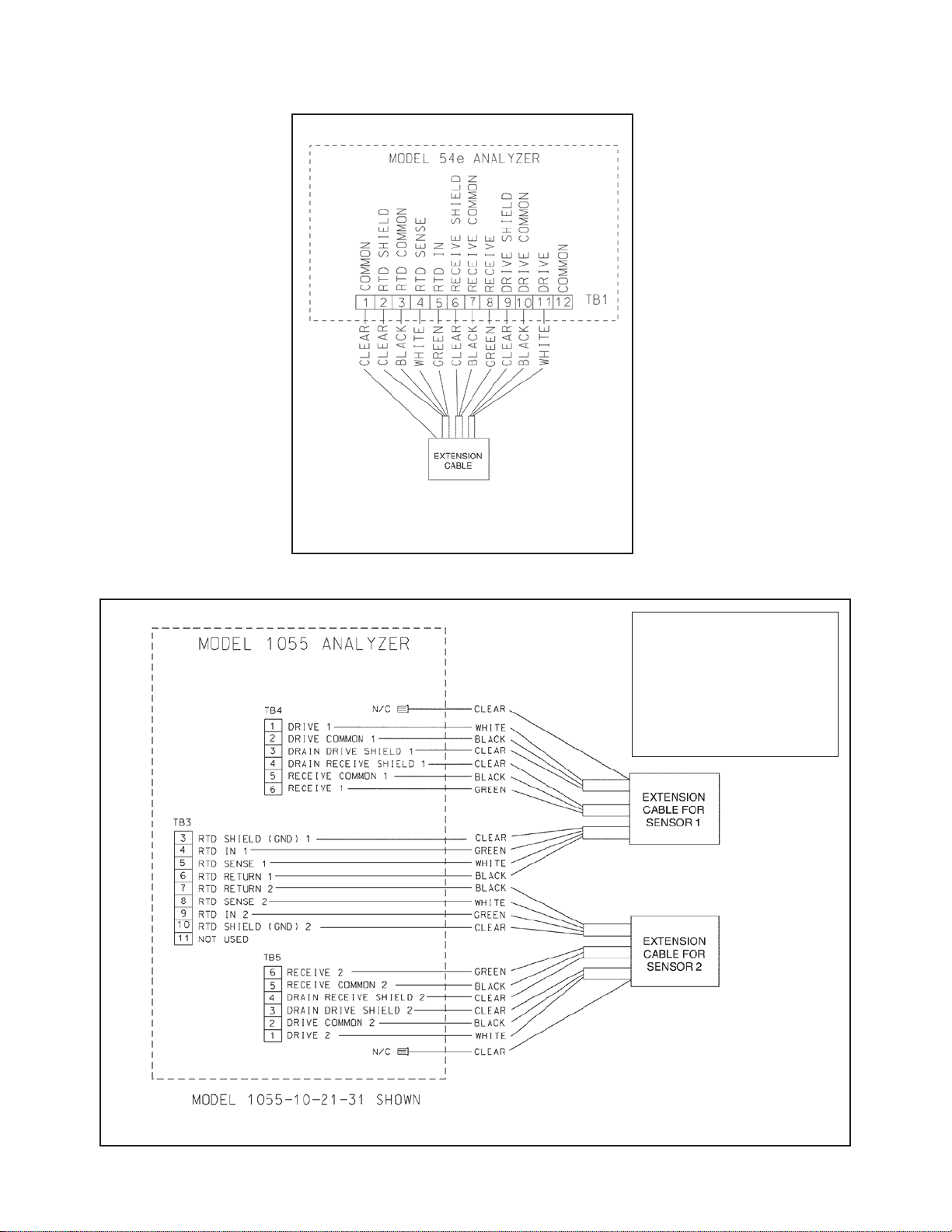
5. Connect the 11 wires of the i nstrument-end of the
extension cable according to the applicable diagram from Figures 1-10 through 1-15.
1.5 CALIBRATION
After sensor and transmitter/analyzer wiring is completed, calibrate the sensor.
NOTE
Most analyzers require the input of the approximate
sensor cell constant bef ore the ana lyzer c alcul ates th e
true cell constant. The nominal cell constant of the
Model 242 sensor dep ends on the size of the se nsor
and the terminal to which the rec eive wire of the inter connecting cable is attached. Refer to Table 1-1 for
the appropriate nominal cell constant value.
TABLE 1-1: Nominal Cell Constants for 242 Sensors
wire (from black-green-clear bundle) of the interconnecting cable is attached to either the black wire terminal or
the orange wire terminal in the sensor junction box. See
10
FIGURE 1-9. Extension Cable
Page 15
MODEL 242
MODEL 242 SENSOR
NOTE: If wiring to a single
21 or to a dual
31, the toroidal sensor is
Blocks
3 and 4. If wiring 2 sensors to
use
SECTION 1.0
FIGURE 1-10. Extension Cable to
Model 54eC Wiring
FIGURE1-11. Extension Cable to Model 1055 Wiring
channel 1055channel 1055-21-xx or 1055xxwired only to Terminal
a dual toroidal 1055-21-31,
TB 3, 4, and 5 as shown.
11
Page 16
MODEL 242
MODEL 242 SENSOR
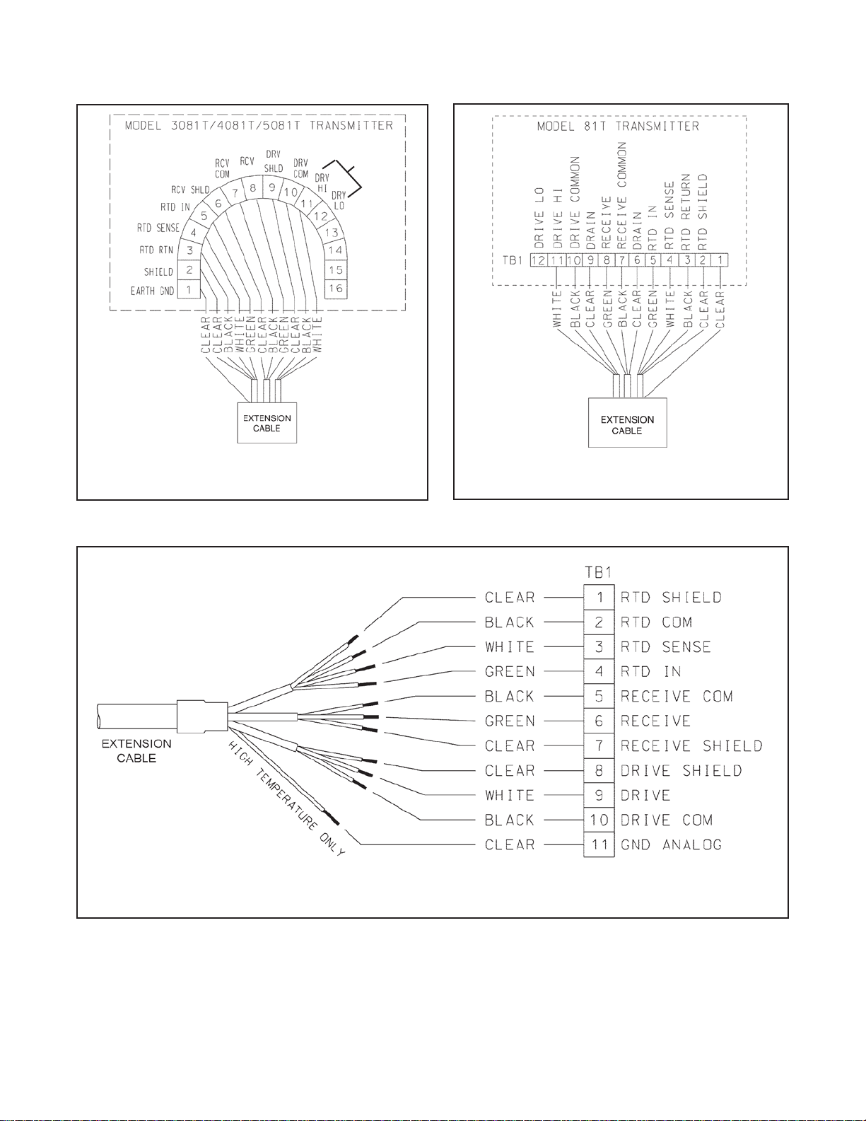
SELECT
*
HI OR
* Applies only to 3081T
and 4081T.
FIGURE 1-12. Extension Cable to Models 3081T,
4081T, and 5081T Wiring
LO
SECTION 1.0
12
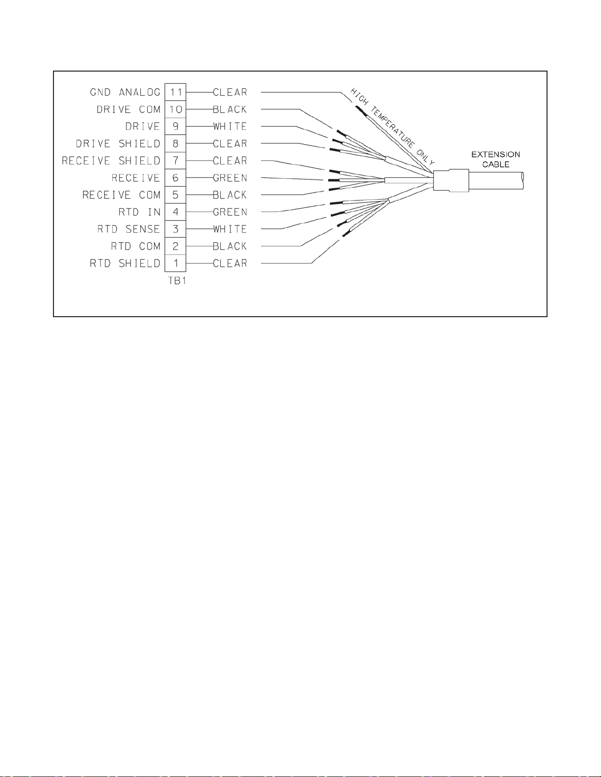
FIGURE 1-14. Extension Cable to Model Xmt Pipe/Wall Mount Enclosure
FIGURE 1-13. Extension Cable to Model 81T
Wiring
Page 17
MODEL 242
MODEL 242 SENSOR
SECTION 1.0
A. To perform liquid calibratio n prior to instal ling the sens or in the process li ne, first seal one e nd of the sens or,
and then proceed with the following steps.
1. Stand the sensor on the sealed end.
2. Fill the sensor completely with a standard conductivity solution.
3. Insert the Pt100 RTD into the contact ring.
4. Adjust the analyzer reading so that it matches the conductivity of the standard solution at the solution tem-
B. Use of the Integral Calibration Loop Wire: This internal wire can be used to facilitate future in-process loop cal-
ibration and to p erf orm a quick verificatio n that the loo p is f unctionin g properly. Performing this ad ditio nal (b ut
optional) step is highly recommended.
1. The sensor must be empty of all fluids, reasonably clean, and preferably completely dry.
2. Attach a variable resistance decade box to the sensor yellow “Cal Loop” wires (in the junction box).
3. Adjust the applied resistan ce until the instrum ent reads the s ame conductivit y value that it did dur ing the
4. To recalibrate the loop at a later d ate, o ptim al res ults will be ach ieve d if the s ensor is retur ned to a cond i-
1.6 MAINTENANCE
The only routine m aintenance required during the operational life of the sensor is to ensure that there are n o
deposits plugging the sens or or coating the inside of the contac t rings. Some custom ers find it advantageous t o
periodically replace process gaskets and/or re-tighten the flange bolts to ensure adequate process seals. Refer to
Figure 1-6 for flange bolting sequence and torque recommendations.
FIGURE 1-15. Extension Cable to Model Xmt Panel Mount Enclosure
perature. Refer to the analyzer/ transmitter instruction manual for complete calibration procedures.
liquid calibration process. Record the conductivity, applied resistance value, and temperature for future reference.
tion approximating its condition d ur in g t he in it ial p er f or mance of steps C.1 to C.3 above. If this is no t possible, the sensor mus t at least be empty of process f luids. Reapply the sam e resistance to the Cal Loop
and adjust the instrument reading.
13
Page 18

MODEL 242
SECTION 2.0
Connection
TABLE 2-2 Sensor Wire Resistance Values
Resistance
(Wire colors are for sensor wires unless indicated)
GREEN
GREEN
GREEN to GROUND screw in J
MegOhms
GREEN
GREEN
WHITE
WHITE to
MegOhms
WHITE
WHITE
YELLOW
YELLOW to GROUND screw in J-box (GRAY wire) > 20 MegOhms
TABLE 2-1 Resistance Values for Pt100 RTD
C = Celsius / F = Fahrenheit
Temperature
Resistance
(°C/°F)
(Ohms)
27 / 80.6
110.4
SECTION 2.0
TROUBLESHOOTING
2.1 TROUBLESHOOTING. The simplest method of trou-
bleshooting is to run a r esistance test on the inducti ve
sensing device. It is also recommended to check the
resistance of the RT D and resistance between vari ous
pairs of the sensor wires.
To perform a quick resistance check of the sensor, recall
the data obtained during Part C of the Calibration
Process (Refer to Sect ion 1. 5) With the sensor empty of
process fluids (preferably also clean and dry), reapply
the resistance to the sensor yellow Cal Loop wires in the
junction box. The reading should be with ±20% of the
original value.
To check the RTD, measure the resistance across th e
RTD wires. See Figure 1-4. The resistance value should
be close to the value shown in Table 2-1.
TROUBLESHOOTING
18 / 64.4 106.9
19 / 66.2 107.3
20 / 68.0 107.7
21 / 69.8 108.1
22 / 71.6 108.4
23 / 73.4 108.9
24 / 75.2 109.2
25 / 77.0 109.6
26 / 78.8 110.0
Refer to Figure 2-1 for a circuit d iagram of the sensor to
use as an aid when perform ing the resistance checks.
Use Table 2-2 to determ ine the resistance values that
should be found across various pairs of sensor wires.
to ORANGE < 1 Ohm
to BLACK 1 to 5 Ohms
-box (GRAY wire) > 20
to WHITE > 20 MegOhms
to YELLOW > 20 MegOhms
to GRAY < 1 Ohm
GROUND screw in J-box (GRAY wire) > 20
to YELLOW > 20 MegOhms
to RED > 20 MegOhms
to YELLOW < 1 Ohm
14
Page 19

MODEL 242
MODEL 242 SENSOR
SECTION 2.0
*The green wire from the extension cable’s black-green-clear bundle might be connected opposite the
sensor’s orange wire, as indicated by
* to utilize the sensor’s alternative cell constant.
FIGURE 2-1. Sensor Circuit for Troubleshooting
15
Page 20

SECTION 3.0
Before removing the s enso r from the process piping,
rings inside the sensor:
ring replacement kits
To distinguish the
ring is less than
ring. The size difference is
rings are
rings have the
ring is less than
ring. The size difference is
rings are
MODEL 242
REPLACEMENT PARTS
SECTION 3.0
REPLACEMENT PARTS
3.1 GENERAL
When replacement parts are required, ensure that
qualified people install the parts specified by
Rosemount. Replacem ent of original com ponents with
those constructed from alternative materials might
change the temperature, pressure, and/or performance
specifications from those of the original configuration
and will void an y CSA, FM, and BASEEFA/CENELEC
agency approvals th at were applicable to the origin al
device. Table 3-1 lists the replacement parts kits for the
Model 242 Sensor. An instruction manual is included
with each kit.
3.2 REMOVE THE SENSOR
CAUTION
ensure that the process ha s been shut do wn and liquid drained from the sensor line. For personal safety,
The RTD can be removed either before or after the
sensor is rem oved from the proc ess. T he junction bo x
should be left attached to the toroid subassembly. After
ensuring that it is s afe to remove the s ensor from the
process line, loosen the flange bolts in 1/ 3 increm ents
in the same order in which they were tightened as
shown in Figure1-4. Remove the bolts and sensor.
3.3 DISASSEMBLE THE SENSOR
NOTE REGARDING O-RINGS
There are two pairs of Oprocess O-rings (item 6) and secondary or backup
O-rings (item 7). Ref er to Figure 3-1 to i dentif y these
items. The two pairs of O -rings are not interchangeable.
Older O-ring replacement kits contained onl y the pai r
of process O-rings. New Ocon- tain both pairs of O-rings.
process O-ring from the backup O-ring:
For sensors with plastic liners:
1. The process O-ring has a much smaller cross sectional area than the sec ondar y O-ring. The c rosssection diameter of the process O-ring is 0.07 in.
The cross-section diameter of the secondary O-ring
is 0.139 in.
2. The diameter of the process Othe secondary Oimmediately obvious when the two Oallowed to dangle from a pencil.
For sensors with alumina liners:
1. The process and secondary Osame cross sectional area. (0.139 in).
2. The diameter of the process Othe secondary Oimmediately obvious when the two Oallowed to dangle from a pencil.
Using the tool indicated in Table 3-2, remove the
Sensor Bolts (Item 2). Note that these bolts were
installed using a thre ad-locking adhesive. Any use of
heat to loosen the adhesive should not exceed the temperature ratings of the s ensor. Figure 3-1 is an ex p loded view of the all the parts of the Model 242 sensor.
16
Page 21

MODEL 242
PART NUMBER
DESCRIPTION
4081T, 5081-T, and Xmt-T (Specify length)
KIT PN
DESCRIPTION
FOR SENSOR MODELS
24005-00
Kit, Liner, 1” DN 25, Teflon PTFE
242-02[ ]TE[ ]
24005-01
Kit, Liner, 1” DN 25, glass-filled PEEK
242-02[ ]G4[ ]
24005-02
Kit, Liner, 1” DN 25, Alumina
242-02[ ]A4[ ]
24006-00
Kit, Liner, 1-1/2” DN 40, Teflon PTFE
242-03[ ]TE[ ]
24006-01
Kit, Liner, 1-1/2” DN 40, glass-filled PEEK
242-03[ ]G4[ ]
24007-00
Kit, Liner, 2” DN 50, Teflon PTFE
242-04[ ]TE[ ]
24007-01
Kit, Liner, 2” DN 50, glass-filled PEEK
242-04[ ]G4[ ]
24007-02
Kit, Liner, 2” DN 50, Alumina
242-04[ ]A4[ ]
24008-00
Kit, Liner, 3” DN 80, Teflon PTFE
242-06[ ]TE[ ]
24008-01
Kit, Liner, 3” DN 80, glass-filled PEEK
242-06[ ]G8[ ]
24008-02
Kit, Liner, 3” DN 80, Alumina
242-06[ ]A8[ ]
24009-00
Kit, Liner, 4” DN 100, Teflon PTFE
242-08[ ]TE[ ]
24009-01
Kit, Liner, 4” DN 100, glass-filled PEEK
242-08[ ]G8[ ]
24009-02
Kit, Liner, 4” DN 100, Alumina
242-08[ ]A8[ ]
KIT PN
DESCRIPTION
FOR SENSOR MODELS
24010-00
Kit, O-Ring, 1” DN 25, EPDM
242-02[ ]EP[ ]
24010-01
Kit, O-Ring, 1” DN 25, Viton
242-02[ ]VT[ ]
24010-02
Kit, O-Ring, 1” DN 25, Chemraz
242-02[ ]F4[ ]
24010-03
Kit, O-Ring, 1” DN 25, Chemraz for use with Alumina liner
242-02[ ]A4-F4
24011-00
Kit, O-Ring, 1-1/2” DN 40, EPDM
242-03[ ]EP[ ]
24011-01
Kit, O-Ring, 1-1/2” DN 40, Viton
242-03[ ]VT[ ]
24011-02
Kit, O-Ring, 1-1/2” DN 40, Chemraz
242-03[ ]F4[ ]
24012-00
Kit, O-Ring, 2” DN 50, EPDM
242-04[ ]EP[ ]
24012-01
Kit, O-Ring, 2” DN 50, Viton
242-04[ ]VT[ ]
24012-02
Kit, O-Ring, 2” DN 50, Chemraz
242-04[ ]F4[ ]
24012-03
Kit, O-Ring, 2” DN 50, Chemraz for use with Alumina liner
242-04[ ]A4-F4
24013-00
Kit, O-Ring, 3” DN 80, EPDM
242-06[ ]EP[ ]
24013-01
Kit, O-Ring, 3” DN 80, Viton
242-06[ ]VT[ ]
24013-02
Kit, O-Ring, 3” DN 80, Chemraz
242-06[ ]F8[ ]
24013-03
Kit, O-Ring, 3” DN 80, Chemraz for use with Alumina liner
242-06[ ]A8-F8
24014-00
Kit, O-Ring, 4” DN 100, EPDM
242-08[ ]EP[ ]
24014-01
Kit, O-Ring, 4” DN 100, Viton
242-08[ ]VT[ ]
24014-02
Kit, O-Ring, 4” DN 100, Chemraz
242-08[ ]F8[ ]
MODEL 242 SENSOR
TABLE 3-1. Replacement Parts and Accessories
23909-00 Extension cable, Pre-prepped, for connection to Instrument Models 54eC, 1055, 3081T,
SECTION 3.0
24014-03 Kit, O-Ring, 4” DN 100, Chemraz for use with Alumina liner 242-08[ ]A8-F8
17
Page 22

MODEL 242
Sensor Type
Model
Wrench
Torque (ft-lbs)
Torque (N-m)
1", 150# flange
242-02-10
5/16" Hex Allen
18 ft-lbs
24 Nm
1", 300# flange
242-02-11
5/16" Hex Allen
18 ft-lbs
24 Nm
DN 25, PN 16
242-02-14
5/16" Hex Allen
18 ft-lbs
24 Nm
1.5", 150# flange
242-03-10
5/16" Hex Allen
18 ft-lbs
24 Nm
1.5", 300# flange
242-03-11
3/8" Hex Allen
42 ft-lbs
57 Nm
DN 40, PN 16
242-03-14
5/16" Hex Allen
18 ft-lbs
24 Nm
2", 150# flange
242-04-10
5/16" Hex Allen
18 ft-lbs
24 Nm
2", 300 # flange
242-04-11
3/8" Hex Allen
42 ft-lbs
57 Nm
DN 50, PN 16
242-04-14
3/8" Hex Allen
42 ft-lbs
57 Nm
3", 150# flange
242-06-10
3/4" Socket
42 ft-lbs
57 Nm
3", 300 # flange
242-06-11
3/4" Socket
42 ft-lbs
57 Nm
DN 80, PN 16
242-06-14
3/4" Socket
42 ft-lbs
57 Nm
4", 150# flange
242-08-10
3/4" Socket
42 ft-lbs
57 Nm
4", 300 # flange
242-08-11
3/4" Socket
42 ft-lbs
57 Nm
DN 100, PN 16
242-08-14
3/4" Socket
42 ft-lbs
57 Nm
Table 3-2. Sensor Bolt Removal & Installation Guide
SECTION 3.0
MODEL 242 SENSOR
* REPLACEMENT PARTS AVAILABLE.
FIGURE 3-1. Exploded View of Model 242
18
Page 23

MODEL 242
MODEL 242 SENSOR
SECTION 3.0
3.4 RE-ASSEMBLE THE SENSOR
It is recommended that a press be used during the assembly process to ensure tight seals between components.
Locate the part to be changed o n the diagram and substitute the new par t from the kit. Complete disassem bly
of the sensor might no t be necessary and in that case is not rec ommended. If new O-rings are to be used, the y
should be lubricated prior to installation.
Assuming the sensor has been completely disass embled, begin by placing bot h Contact Rings (Item 1) side by
side on their flat f aces. Set a Flange (Item 4) on eac h Contact Ring (Item 1). Install a Retainer Ring (Item 5)
onto the step on the outs ide of each Contact Ring (Item 1) . Insert a lubricated Process O-ring (Item 6) in the
lower groove (closest to the flat fac e) located inside each Contact R ing (Item 1). Place a lubr icated Secondary
Back-up O-ring (Item 7) on the upper step insid e each Contact Ring (Item 1). The flange-assem bly should look
like Figure 3-2.
Place one of these flange-assemblies onto a press a nd install the Liner (Item 8). It is advisabl e to place a flat
surface between the pr es s and the liner to protect the l iner f r om damage during pressing. Be c ar ef ul t o ensure Orings do not slip or twist. Slip the Toroid Housing (Item 9) over the Liner (Item 8) to nest inside the flangeassembly. The pins on the toroid hous ing m ust seat into the sm all hol es in the f langes. Place the s econd flangeassembly on top of the first flange assembly with the Liner (Item 8) and Toroid Housing (Item 9) in between.
Check for pin alignm ent, pinched O-rings, and straight, e ven insertion. The Sensor Bolts (Item 2) can be temporarily preplaced in t he bolt holes to align the two Flanges . Press the entire sensor together to begin assem-
bly of all the com ponents. Install and tighten the Sensor Bolts and Nuts (Items 2 and 3), using thread-locking
compound. Using th e torquing sequence shown in Figure 1-6, t ighten the bolts in 1/3 increm ents of their final
torque values as listed in Table 3-2.
Back-up O-ring
Contact Ring
Process O-ring
Retainer Ring
Flange
FIGURE 3-2. Flange Assembly: Contact Ring, Flange, and O-rings.
3.5 RE-INSTALL THE SENSOR INTO THE PROCESS
Please see Section 1.4 of this manual for instructions.
Page 24

LIQ-MAN-242
Rev. F
June 2017
www.Emerson.com/RosemountLiquidAnalysis
Youtube.com/user/Rosemount
Twitter.com/Rosemount_News
Emerson Automation Solutions
8200 Market Blvd.
Chanhassen, MN 55317,
USA
Tel +1 800 999 9307
Fax +1 952 949 7001
Liquid.CSC@Emerson.com
Analyticexpert.com
facebook.com/Rosemount
©2017 Emerson Automation Solutions. All rights reserved.
The Emerson logo is a trademark and service mark of Emerson Electric Co. Rosemount is a mark of
one of the Emerson family of companies. All other marks are the property of their respective
owners.
The contents of this publication are presented for information purposes only, and while effort has
been made to ensure their accuracy, they are not to be construed as warranties or guarantees,
express or implied, regarding the products or services described herein or their use or applicability.
All sales are governed by our terms and conditions, which are available on request. We reserve the
right to modify or improve the designs or specifications of our products at any time without notice.
 Loading...