

Page 1
Instruction Manual
LIQ-MAN-222
Rev.D
June 2017
Rosemount
222
Toroidal Flow-Through Conductivity Sensor
TM
Page 2
SPECIFICATIONS
Flange
Option
Temperature
Pressure
150 lb
-01 and -02
41°F(5°C) - 360°F (182°C)
125 psig (963 kPa abs)
Flange
Option
Pressure (max)
150 lb
-01 and -02, and -01-21
125 psig (963 kPa abs)
300 lb
200 psig (1480 kPa)
300 lb
-06 (2 inch)
250 psig (1825 kPa abs)
Wetted Materials: Teflon-lined carbon ste el pi pe, with c arbon stee l outer fla nges. O ptio n-21 has 316 SS outer
flanges.
Temperature and Pressure:
300 lb -05 and -06 41°F(5°C) - 360°F (182°C) 250 psig (1825 kPa abs)
Pressure (for CRN registration only):
-05 (1 inch)
Outside flanges: ANSI B16.5 raised face, threaded.
INSTALLATION
First, decide whether the initial calibration will be done in the shop before installing the sensor or in the process piping
after installing the sensor. Refer to the Calibration section for information about in-shop and in-process calibrations.
NOTE
Install the sensor in a location where it will be completely filled with process liquid.
A vertical pipe run with the flow from bottom to top is best.
1.
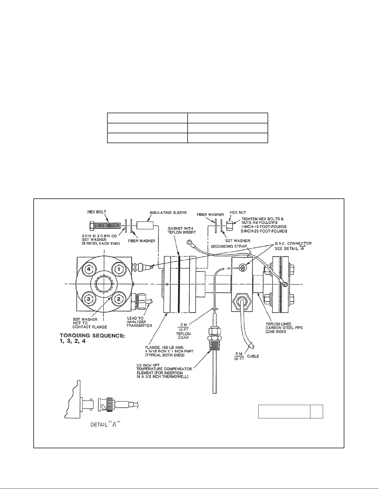
Remove the grounding strap from the outer flanges. See Figure 1. Save the strap and all the hardware for
reassembly.
2.
Carefully remove the nuts, bolts, insulating bushings, and washers from the flanges. Save the parts. They
will be needed later and must be in good condi tion. Separate the flange sets.
3.
Remove and save the flange gaskets.
4.
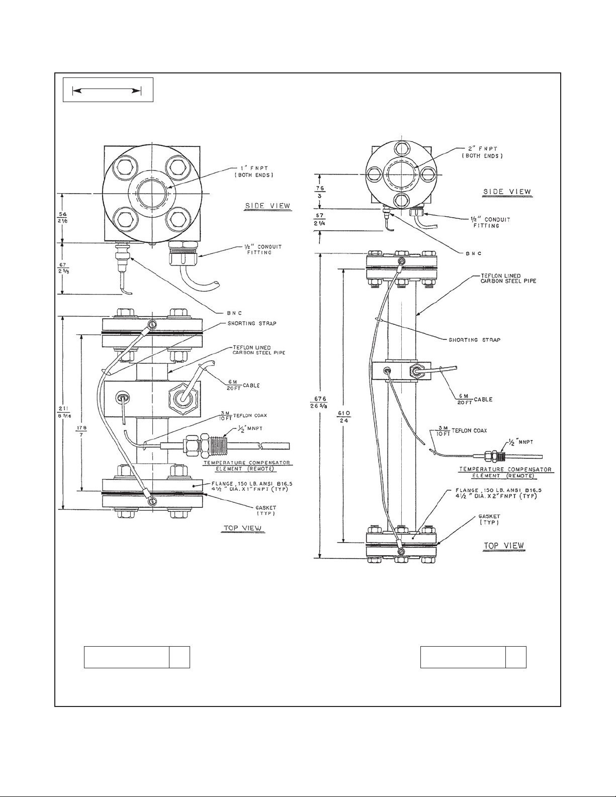
Install the outer flanges on the process piping, observing the dimensions noted in Figures 2 and 3. Use pipe
joint compound or pipe tape to ensure the connections do not leak.
5.
Install a ½ inch FNPT thermowell in the process piping within 6 ft. (1.8m) of the sensor. For best results place
the thermowell as close as possible to the sensor.
6.
Position the sensor between the process mating flanges with the flange gaskets inserted between each set
of flanges. If the process piping is lined with a non-conductive material, a metal orifice plate (contact ring)
must be installed between the flanges. Consult the factory for more information.
7.
Align the bolt holes.
8.
Insert an insulating sleeve in each bolt hole. See Figure 1.
9.
Place a metal washer on each bolt, followed by an insulating washer. Insert the bolt through the insulating
sleeve.
10.
Place an insulating washer f ollowe d a metal washer on each bolt.
Page 3
222
INSTALLATION
2
Flange
Torque
1 inch flange bolts
10 ft-lb (7.37 N-m)
2 inch flange bolts
25 ft-lb (18.43 N-m)
NOTE
Before tightening the bolts (step 11), be sure the flange gaskets are installed between the
system piping and the sensor and that the insulating sleeves and washers are in place.
For the sensor to operate properly there must no metal to metal contact between the sensor
and the process piping.
11.
Screw a nut onto each bolt and tighten according to the table. Follow the torquing sequence shown in Figure 1.
Do not over tight-
en the bolts.
12.
Connect the grounding strap between the two outer f langes us ing the screws and washer s rem oved in step 1.
If an orifice plate contact ring is being used, connect the shorting strap to the two contact rings.
13.
Install the temperatur e sensor in the thermowel l. Use Teflon tape on the pipe thr e ads . The insertion length is
adjustable from 1.4 to 4.0 i nches (36 to 102 m m) . The temperatur e sensing zone, which exten ds 1.3 inches
(33 mm) from tip of the sensor, must be inside the thermowell
FIGURE 1. 222 Toroidal Conductivity Sensor/Assembly Installation
DWG. NO. REV.
40022208
D
Page 4
222
INSTALLATION
3
MILLIMETER
INCH
Model 222-01 Model 222-02
DWG. NO. REV.
40022210 A
DWG. NO. REV.
40022211 B
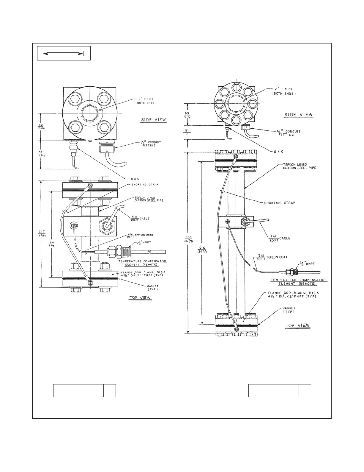
FIGURE 2. Code-01 and -02 Dimensions
Page 5
222
INSTALLATION
4
MILLIMETER
INCH
DWG. NO. REV.
222-05 222-06
40022212 A
DWG. NO. REV.
40022213 B
FIGURE 3. Code-05 and -06 Dimensions
Page 6

5
222
WIRING
222
FIGURE 6. Wiring 222 sensor to 54eC analyzer
WIRING
Keep sensor wiring away from ac conductors and high current demanding equipment. Do not cut cable.
Cutting the cable may void the warranty.
FIGURE 4. Wire Functions
222
FIGURE 5. Wiring 222 sensor to 1056 and 56 analyzers
Page 7

6
222
WIRING
TB2
RTN
SENSE
RTD IN
SHLD
TB1
RCV B
RCV A
RSHLD
DRV B
DSHLD
22282-524
FIGURE 9. Wiring 222 sensor to 1066 transmitter
GREEN
CLEAR
GREEN
222
FIGURE 7. Wiring 222 sensor to Xmt-T panel mount transmitter
222
FIGURE 8. Wiring 222 sensor to Xmt-T pipe/wall mount tra n smitter
WHITE
BLACK
WHITE
BLACK
DRV A
222
FIGURE 10. Wiring 222 sensor to 5081-T
transmitter
Page 8

7
222
WIRING
WIRING THROUGH A REMOTE JUNCTION BOX
222
FIGURE11. Wiring sensor through a remote junction box
Wire cable point to point. For wiring at the analyzer end, refer to the appropriate analyzer wiring diagram.
FIGURE 12. Remote Junction Box (PN 23550-00)
Page 9

8
222
TROUBLESHOOTING
CALIBRATION
The nominal cell constant of the 1-inch diameter sensor is 6/cm and the nominal cell constant of the 2-inch diameter
sensor is 4/cm. The error in the cell constant is about ±10%, so conductivity readings made using the nominal cell
constant will have an error of at least ±10%. For higher accuracy the sensor must be calibrated.
The sensor can be calibrated using a standard solution or a previously calibrated sensor and analyzer. Calibration
against a standard solution requires that the sensor and outer flanges be removed from the process piping.
Generally it is a useful m ethod onl y when the sensor is f irst installe d. Other wise, the s ensor s hould b e calibr ated
in place against a referee sensor and analyzer.
To calibrate agains t a stan dard solut ion, scr ew a shor t length of metal p ipe into one of th e outer f langes and cap
the open end of the pipe. Stand the sensor on the cappe d end and fill it with standar d to the level of the upper
surface of the second outer flange. Be sure t he shorting strap is connected to b oth flanges. Adjust t he analyzer
reading to match the k nown cond uctivit y of the stan dard. Do n ot place a tem pera ture sensor or an y object ins ide
the conductivity sensor d uring calibrat ion. Doing so will alter the meas ured conductivit y and introduce an error in
the measurement.
Once the sensor has been installed in the process piping, r emoving it for calibration is impractical. In this case,
calibrate the sensor aga inst a referee sens or and analyzer, ideall y while both sensors are simultaneously m easuring the same proc ess liquid. If this is not practical, c alibrate the sensor ag ainst the results of a measurement
made on a grab sample.
For more information about calibrating toroidal conductivity sensors, particularly precautions to take during inprocess calibrations, refer to application sheet ADS 43-025, available on the Rosemount Analytical website.
Page 10

9
222
CALIBRATION
PROBLEM
PROBABLE CAUSE
SOLUTION
Sensor is not filled with process liquid.
Confirm that the sensor is installed in the
TROUBLESHOOTING
Off-scale reading Wiring is wrong.
RTD is open or shorted. Check RTD for open or shorts. See Figure 13.
Sensor is damaged.
Noisy reading
Reading seems wrong
(lower or higher than
expected)
Fluctuating process liquid level in
the sensor.
Sensor cable is run near high voltage conductors.
Sensor cable is moving. Keep the sensor cable stationary.
Bubbles are trapped in the sensor Increase the flow if possible.
Cell constant is wrong.
Wrong temp erat ure c orr ect ion a lgo-
rithm is being used.
Verify and correct wiring.
Perform isolation checks. See Figure 13.
Perform toroid check.
Confirm that the sensor is installed in the
process piping so that it is always filled with liquid. Installation in a vertical pipe run with flow
from the bottom is best.
Move the cable away from high voltage
conductors.
process piping so that it is always filled with liquid. Installation in a vertical pipe run with flow
from the bottom is best.
Calibrate the sensor.
Check that the temperature correction is appro-
priate for the sample. See analyzer manual for
more information.
Temperature reading is inaccurate.
Measured temperature does not
match temp er atur e at the sensor.
Toroids are damaged.
Disconnect the RTD leads (Figure 13) and
measure the resistance between the in and
common leads. The resistance should be close
to the value in Table 1.
Move the thermowell and RTD closer to the
sensor.
Perform toroid check.
Page 11

10
222
MAINTENANCE
Temperature
Resistance
119.4 Ω
1-inch sensor
2-inch sensor
100 Ω
60 mS/cm
40 mS/cm
FIGURE 13. Disconnect wires from analyzer before measuring resistance.
TABLE 1.
10°C
20°C
25°C
30°C
40°C
50°C
Checking toroid operation
Use the following procedure to check the operation of the toroids.
1.
Disconnect the shorting strap from one of the outer flanges. The conductivity reading will drop to zero.
2.
Pass a short piece of heavy gauge wire through the space between the toroid assembly and the pipe.
3.
Connect the ends of the wire to a resistance decade box.
4.
Turn off temperature correction in the analyzer. If raw conductivity is available as a temperature compensation
selection, choose raw. If raw is not available, choose manual temperature correction and set the temperature
to 25°C (77°F).
5.
Adjust the resistance to the values shown in the table below. The conductivity reading displayed by the analyzer
should be close to the values shown.
The toroids are working properly if increasing the resistance by a factor of two causes the displayed conductivity
to decrease by a factor of two.
103.9 Ω
107.8 Ω
109.7 Ω
111.7 Ω
115.5 Ω
Resistance
200 Ω 30 mS/cm 20 mS/cm
K = 6/cm
K = 4/cm
Page 12

11
222
TROUBLESHOOTING
PN
Description
2002557
Insulation kit, 1 inch, 150 lb flange, 2 sets (See Note)
2002559
Insulation kit, 2 inch, 150 lb flange, 2 sets (See Note)
2002560
Insulation kit, 2 inch, 300 lb flange, 2 sets (See Note)
8950101
Pt 100 RTD assembly
23294-00
Interconnecting cable, specify length (maximum 100 ft (30.5m))
REPLACEMENT PARTS
2002558 Insulation kit, 1 inch, 300 lb flange, 2 sets (See Note)
Note: Each insulation kit contains two flange ga skets and sufficient insulatin g sleeve s, in sulating washer s, and stainless steel washers to replace both flange seal s of one sensor. The kit does not contain flange bolts or nuts.
Page 13

Page 14

LIQ-MAN-222
Rev. D
June 2017
www.Emerson.com/RosemountLiquidAnalysis
Youtube.com/user/Rosemount
Twitter.com/Rosemount_News
Emerson Automation Solutions
8200 Market Blvd.
Chanhassen, MN 55317,
USA
Tel +1 800 999 9307
Fax +1 952 949 7001
Liquid.CSC@Emerson.com
Analyticexpert.com
facebook.com/Rosemount
©2017 Emerson Automation Solutions. All rights reserved.
The Emerson logo is a trademark and service mark of Emerson Electric Co. Rosemount is a mark of
one of the Emerson family of companies. All other marks are the property of their respective
owners.
The contents of this publication are presented for information purposes only, and while effort has
been made to ensure their accuracy, they are not to be construed as warranties or guarantees,
express or implied, regarding the products or services described herein or their use or applicability.
All sales are governed by our terms and conditions, which are available on request. We reserve the
right to modify or improve the designs or specifications of our products at any time without notice.
 Loading...